Recent Development of FinFET Technology for CMOS Logic and Memory
|
|
|
- Bernadette Murphy
- 5 years ago
- Views:
Transcription
1 Recent Development of FinFET Technology for CMOS Logic and Memory Chung-Hsun Lin EECS Department University of California at Berkeley
2 Why FinFET Outline FinFET process Unique features of FinFET Mobility, workfunction engineering, corner r effect,, QM, volume inversion Issues Recent FinFET Develop Triple-gate FinFET, Omega FET, Nanowire FinFET, Independent gate, Multi-channel FinFET, Metal-gate/high gate/high-k FinFET, Strained FinFET,, Bulk FinFET Memory DRAM, SONOS, SRAM Conclusion NTUEE Seminar 2006/04/29 Chung-Hsun Lin -2
 10 LOW POWER HIGH")

3 MOSFET Scaling ITRS 2001 Projection 100 The first transistor 1947 Technology Scaling The Power5 microprocessor GATE LENGTH (nm) 10 LOW POWER HIGH PERFORMANCE YEAR Investment Market Growth Better Performance/Cost Same transistor design concept NTUEE Seminar 2006/04/29 Chung-Hsun Lin -3

4 Scaling : Moore s s law Technology Drivers Reduced cost / function Improved performance Greater circuit functionality Source: Intel NTUEE Seminar 2006/04/29 Chung-Hsun Lin -4


5 Bulk-Si MOSFET Scaling Issues Leakage current is the primary barrier to scaling To suppress leakage, we need to employ: Higher body doping lower carrier mobility, higher junction capacitance, increased junction leakage Thinner gate dielectric higher gate leakage Ultra-shallow S/D junctions higher Rseries G Desired characteristics: L g - High ON current (I dsat ) T ox S - Low OFF current Gate D courtesy of Prof. Kuroda Keio University Source Substrate L eff X j Drain N sub NTUEE Seminar 2006/04/29 Chung-Hsun Lin -5

6 Issues for Scaling L g to <25 nm V T variation (statistical dopant fluctuations) Leakage Incommensurate gains in I dsat with scaling limited carrier mobilities parasitic resistance NTUEE Seminar 2006/04/29 Chung-Hsun Lin -6


7 Advanced MOSFET Structures Leakage can be suppressed by using a thin body Ultra-Thin Body Double Gate Source Gate SOI SiO 2 Drain T BOX Silicon Substrate T Si Source T ox Gate 1 SOI Gate 2 V g Drain T Si NTUEE Seminar 2006/04/29 Chung-Hsun Lin -7
8 Thin-Body MOSFETs Control short-channel effects with T body No channel doping needed! Relax gate oxide (T ox ) scaling Double-Gate is even more effective Scalable to 10nm gate lengths Gate Gate Source Drain Source Drain Buried Oxide Substrate Ultra-Thin Body T body Gate Double-Gate NTUEE Seminar 2006/04/29 Chung-Hsun Lin -8
9 Electric Field Reduction Reduced vertical field in DG and UTB E eff = ηq inv ε No doping = No Q depl! + Q Si Expected to benefit: Mobility Gate Leakage depl Gate Bulk Gate Buried Oxide Substrate Thin-Body Q inv Q depl Q inv NTUEE Seminar 2006/04/29 Chung-Hsun Lin -9
10 Thin-Body MOSFETs Control short-channel effects with T body No channel doping needed! Relax gate oxide (T ox ) scaling No channel doping needed! I on Improved mobility Lower vertical electric field No impurity scattering Improved swing Better control of SCE Idrain DG Bulk Vgate C load Lower V T No depletion or junction capacitance Double-Gate is even more effective Scalable to 10nm gate lengths Potentially less V t scatter (dopant fluctuation) NTUEE Seminar 2006/04/29 Chung-Hsun Lin -10
11 Circuit level benefits Thin body devices Good control of SCE Steep Sub-threshold swing Higher I dsat Lower Capacitance - No C junc and C depl Better CV/I delay at lower power FO4 Inverter Delay [ps] T body,utb < 5nm Bulk UTB DG T body,utb = 5nm Technology L gate [nm] Source: Leland Chang NTUEE Seminar 2006/04/29 Chung-Hsun Lin -11
12 Double-Gate MOSFETs S Gate 1 Gate 2 D Current flow Planar DG MOSFET Current flow S Gate 2 D Gate 1 Gate 2 D Gate 1 FinFET Current flow S Vertical DG MOSFET NTUEE Seminar 2006/04/29 Chung-Hsun Lin -12
13 Multi-Gate FinFET Source Gate Gate Drain Gate Gate Drain Gate Drain Gate Drain Source Gate Drain Planar DG-FET Source 90 Rotation Source FinFET Rotation allows for self-aligned gates Layout similar to standard SOI FET NTUEE Seminar 2006/04/29 Chung-Hsun Lin -13
14 FinFET Process Flow Si Fin SiO 2 Resist BOX Si 3 N 4 Spacer SOI Substrate Fin Patterning Poly Poly Gate Deposition/Litho NiSi Gate Etch Spacer Formation S/D Implant + RTA Silicidation NTUEE Seminar 2006/04/29 Chung-Hsun Lin -14

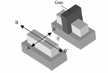
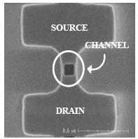
15 FinFET Device Structure Source Gate Drain All features defined by optical lithography and aggressive trimming NTUEE Seminar 2006/04/29 Chung-Hsun Lin -15


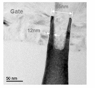
16 10nm FinFET TEM Poly-Si Si Fin NiSi 220Å SiO2 cap Lg=10nm BOX NTUEE Seminar 2006/04/29 Chung-Hsun Lin -16
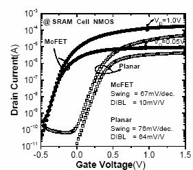
17 10nm FinFET I-VI Dual N + /P + poly gates: - Need V T control Low DIBL NMOS: PMOS: 120 mv/v 71 mv/v Good SCE despite thick T ox (27Å EOT) & W fin (26nm) - Due to large S/D doping gradient & spacer thickness Drain Current [A/μm] V d =-1.2V -0.1V NMOS S=125 mv/dec PMOS S=101 mv/dec Gate Voltage [V] V d =1.2V 0.1V NTUEE Seminar 2006/04/29 Chung-Hsun Lin -17
18 Short-Channel Effects Acceptable DIBL and subthreshold slope down to below 20nm L gate Nearly ideal (60mV/dec) subthreshold slope at long L gate NMOS better than PMOS due to slower As 0 diffusion Subthreshold Slope (mv/dec) NMOS PMOS W fin =26nm Gate Length (nm) DIBL (mv/v) NTUEE Seminar 2006/04/29 Chung-Hsun Lin -18
19 Orientation <100> Gate Source Drain (110) Surface (110) (100) <110> ~(111) (110) Rotation by 45º changes orientation from (110) to (100) Intermediate rotation similar to (111) NTUEE Seminar 2006/04/29 Chung-Hsun Lin -19
20 How Mobility Changes Electron Mobility [cm 2 /Vs] Oxynitride (100) (111) (110) Effective Field [MV/cm] Hole Mobility [cm 2 /Vs] Oxynitride (110) (111) (100) Effective Field [MV/cm] By shifting away from (100): μ e is degraded, μ h is enhanced Can we benefit from changing the N/P ratio? NTUEE Seminar 2006/04/29 Chung-Hsun Lin -20
21 Gate Delay PMOS enhancement (20%) is larger than NMOS degradation (8%) Net delay improvement Trade off μ h and μ e NOR: PMOS stack μ h very important Most improvement NAND: NMOS stack μ h less important Least improvement % Delay Speedup vs. (100) L gate =35nm μ h, μ e NOR Inv (100) (111) (110) Orientation Fanout=4 NAND Oxynitride (100) NMOS (110) PMOS NTUEE Seminar 2006/04/29 Chung-Hsun Lin -21
22 Optimized FinFET Gate Source Drain Source Gate Source Drain (110) PMOS Drain Source (100) NMOS Drain Trade off layout area for performance NTUEE Seminar 2006/04/29 Chung-Hsun Lin -22
23 FinFET Layout Area (100) (110) (111) 45 o N / 90 o P 90 o N / 45 o P Layout Area [μm 2 ] Layout Area [μm 2 ] Inverter I dsatn,p =1.1mA I dsatn,p =110mA Non-(100) orientation saves area Higher PMOS I dsat reduces drawn W 45º orientation is less area efficient for smaller W These devices are small anyway does it matter? Use only in critical path? NTUEE Seminar 2006/04/29 Chung-Hsun Lin -23

24 Hybrid-Orientation-Technology (HOT) Super HOT: SOI version DSB: bulk version NTUEE Seminar 2006/04/29 Chung-Hsun Lin -24
25 V T : What CMOS Needs Need symmetrical V T s for proper CMOS operation Need low V T s for speed V DD Output Inverter Response V IN = V TN V IN = V DD -V TP 0 Input V DD NTUEE Seminar 2006/04/29 Chung-Hsun Lin -25
26 Gate Work Function Threshold Voltage [V] N + Poly V T =0.2V 4.52eV V Tn -V Tp V T =0.4V 4.95eV P + Poly Gate Workfunction [ev] Single gate material V Tn = -V Tp = 0.4V N + /P + Poly V Tn = -V Tp = -0.2V For low body doping, desired Φ M values are: ~ 4.5 ev for NMOS ~ 5.0 ev for PMOS Need two separate work functions for NMOS and PMOS! NTUEE Seminar 2006/04/29 Chung-Hsun Lin -26
27 Molybdenum Φ M Engineering by Ion Implantation Φ M can be lowered by N + implantation and thermal anneal ΔΦ M increases with dose energy (N segregates to SiO 2 interface & forms Mo 2 N) P. Ranade et al., IEDM 2002 Anneal time = 15m except for 900 o C (15s) T Mo = 15nm NTUEE Seminar 2006/04/29 Chung-Hsun Lin -27
28 Mo-Gated FinFETs (PMOS) Y.-K. Choi et al., IEDM 2002 Drain Current, Id [A/um] L g =80nm, T Si =10nm V ds =0.05V V t shift Mo MoN(N 2 =5x10 15 cm -2 ) Gate Voltage, V g [V] V t =0.2V for lightly doped body, and is adjustable by N + implantation Alternative technique: Full silicidication (NiSi) of n+/p+ Si gates (J. Kedzierski et al., W. Maszara et al., Z. Krivokapic et al., IEDM 2002) Potential issues include: - dopant penetration - thermal stability - stress/adhesion - gate dielectric reliability NTUEE Seminar 2006/04/29 Chung-Hsun Lin -28
29 Corner Effect in Triple or More Gates Corner Effect Different V th at corner region Significant subthreshold leakage current Strong corner radius, body doping dependence B. Doyle et al., VLSI Tech., p. 133, 2003 NTUEE Seminar 2006/04/29 Chung-Hsun Lin -29
![Corner Effect [1] Vg=0.](/docs-images/91/104506294/images/30-3.jpg "2 V z Vg=1 V z D y y G S 2D current density distribution 2D current density distribution DESSIS 3-D 3 D")
 z direction y direction Current Density (A/cm 2 ) 4x10 6 3x10 6 2x10 6 1x10 6 z")
30 Corner Effect [1] Vg=0.2 V z Vg=1 V z D y y G S 2D current density distribution 2D current density distribution DESSIS 3-D 3 D device simulator Ideal rectangular fin shape N sub =1e15cm -3 Current Density (A/cm 2 ) Position (nm) z direction y direction Current Density (A/cm 2 ) 4x10 6 3x10 6 2x10 6 1x10 6 z direction y direction Position (nm) NTUEE Seminar 2006/04/29 Chung-Hsun Lin -30
![Corner Effect [2] N sub =5e18cm -3 corner z y Current Density (A/cm 2 ) 2.0x10 7 1.5x10 7 flat Vg=0.2 V 1.0x10 7 5.0x10 6 2D current density distribution 0.0-0.015-0.010-0.005 X Axis 0.000 0.005 0.](/docs-images/91/104506294/images/31-1.jpg "010 0.015 0.000 0.005 0.030 0.025 0.020 0.015 0.010 Y Axis z 4x10 20 y Vg=1 V Electron Density (cm -3 ) 3x10 20 2x10 20 1x10 20 2D current density distribution -0.015-0.010-0.005 0.000 0.005 0.010 NTUEE Seminar 2006/04/29 Chung-Hsun Lin -31 0 X Axis 0.")
31 Corner Effect [2] N sub =5e18cm -3 corner z y Current Density (A/cm 2 ) 2.0x x10 7 flat Vg=0.2 V 1.0x x10 6 2D current density distribution X Axis Y Axis z 4x10 20 y Vg=1 V Electron Density (cm -3 ) 3x x x D current density distribution NTUEE Seminar 2006/04/29 Chung-Hsun Lin X Axis Y Axis
32 3D Simulation w/ Various Shape of Corner Lg=1μm, Wsi=30nm, Hsi=30nm, Tox=1nm R=0, 5, 10, 15m Normalized Drain Current (A/μm) 1E-5 1E-7 1E-9 1E-11 R=15nm R=10nm R=5nm R=0nm 1E Gate Voltage (V) Normalized Drain Current (A/μm) 8.0x x x x10-5 R=15nm R=10nm R=5nm R=0nm Gate Voltage (V) NTUEE Seminar 2006/04/29 Chung-Hsun Lin -32
33 Short Channel Behavior MG device with sharp corner shows better short channel behavior than the rounded corner R=0nm R=15nm DIBL (mv/v) Gate Length (nm) NTUEE Seminar 2006/04/29 Chung-Hsun Lin -33

34 Double-humps induced by cap transistor 30x30nm structure, T ox =3nm, L g =1mm, N sub =5e18cm -3 Cap transistor induced lower V t is very significant. It may attribute to thicker T ox, and more partial depleted. dgm/dvg 4.0x x x x x30nm L g =1μm, T ox =3nm N sub =5e18cm -3 Drain Current (A) 1E-5 1E-7 1E-9 1E-11 1E-13 1E Gate Voltage (V) 1E Gate Voltage (V) NTUEE Seminar 2006/04/29 Chung-Hsun Lin -34
![Volume Inversion [1] Gate Gate Gate Gate edensity edensity 6.1E+13 6.1E+13 5.3E+13 5.3E+13 T si 4.](/docs-images/91/104506294/images/35-2.jpg "5E+13 T si 4.5E+13 3.6E+13 3.6E+13 2.8E+13 2.8E+13 2.0E+13 N sub =10 15 cm -3 N sub =10 18 cm -3 2.")
.")
35 Volume Inversion [1] Gate Gate Gate Gate edensity edensity 6.1E E E E+13 T si 4.5E+13 T si 4.5E E E E E E+13 N sub =10 15 cm -3 N sub =10 18 cm E+13 Oxide Oxide The electron density distribution from the 3-D ISE device simulator. Volume inversion is significant in intrinsic channel SDG (left). NTUEE Seminar 2006/04/29 Chung-Hsun Lin -35
36 Electric Potential (V) 0.6 N sub = cm Volume Inversion [2] ϕ s0, 10nm ϕ s, 10nm ϕ s0, 20nm ϕ s, 20nm Gate Voltage (V) Inversion charge sheet density (C/cm 2 ) 1E For intrinsic channel doping, volume inversion is valid and the potential through the Si film is flat in the subthreshold region. The inversion charge (current) in the subthreshold region is proportional to T si. NTUEE Seminar 2006/04/29 Chung-Hsun Lin -36 1E-5 1E-7 1E-9 1E-11 1E-13 N sub = cm -3 T si Tsi = 10 nm Tsi = 20 nm Gate Voltage (V)
37 QM Surface Potential Correction Undoped case NTUEE Seminar 2006/04/29 Chung-Hsun Lin -37
38 I-V V Verification Model can predict both subthreshold and strong inversion region well. 1E-4 6.0x10⁻⁵ Drain Current (A/μm) 1E-6 1E-8 1E-10 1E-12 Symbols: 2D simulation Lines: Model Classic QM Drain Current (A/μm) 5.0x x x x x10-5 Symbols: 2D simulation Lines: Model Classic QM 1E Gate Voltage (V) Gate Voltage (V) NTUEE Seminar 2006/04/29 Chung-Hsun Lin -38

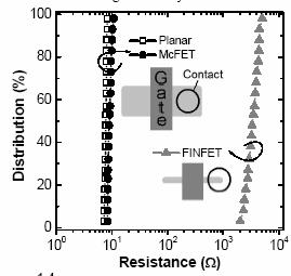
39 S/D Series Resistance Issue J. Kedzierski et al., IEDM 2001 S/D series resistance will degrade the performance of thin body device Can be improved by the selective Si epitaxy raised S/D NTUEE Seminar 2006/04/29 Chung-Hsun Lin -39
40 Why FinFET Outline FinFET process Unique features of FinFET Mobility, workfunction engineering, corner r effect,, QM, volume inversion Issues Recent FinFET Develop Triple-gate FinFET, Omega FET, Nanowire FinFET, Independent gate, Multi-channel FinFET, Metal-gate/high gate/high-k FinFET, Strained FinFET,, Bulk FinFET Memory DRAM, SONOS, SRAM Conclusion NTUEE Seminar 2006/04/29 Chung-Hsun Lin -40

41 Triple-Gate Transistor B. Doyle et al., VLSI Tech NTUEE Seminar 2006/04/29 Chung-Hsun Lin -41

42 Omega-Gate Transistor NTUEE Seminar 2006/04/29 Chung-Hsun Lin -42

43 5nm Nanowire FinFET NTUEE Seminar 2006/04/29 Chung-Hsun Lin -43


44 Independent Gate FinFET Control the threshold voltage Ideal rectangular shape of Si fin NTUEE Seminar 2006/04/29 Chung-Hsun Lin -44

45 Independent Gate FinFET NTUEE Seminar 2006/04/29 Chung-Hsun Lin -45
46 Multi-Channel FinFET NTUEE Seminar 2006/04/29 Chung-Hsun Lin -46

47 Metal Gate FinFET NTUEE Seminar 2006/04/29 Chung-Hsun Lin -47


48 Metal-Gate FinFET K.G. Anil et al., VLSI Tech Vth adjustment Improvement of Ion NTUEE Seminar 2006/04/29 Chung-Hsun Lin -48


49 TiN/HfO2 FinFET Vth adjustment Reduce Gate leakage N. Collaert et al., VLSI Tech NTUEE Seminar 2006/04/29 Chung-Hsun Lin -49

50 Inverted T Channel (ITFET) UTB + FinFET Continuous effective width L. Mathew et al., IEDM 2005 NTUEE Seminar 2006/04/29 Chung-Hsun Lin -50


51 Strained FinFET 25% drain current enhancement of PFET by introducing recessed Si 0.8 Ge 0.2 S/D Compressive stress and raised S/D P. Verheyen et al., VLSI 2005 NTUEE Seminar 2006/04/29 Chung-Hsun Lin -51
52 Impact of Gate-Induced Strain MuGFETs with TiSiN gate (+3GPa stress as deposited) % (100) metal (110) metal (100) poly ref (110) poly ref % (100) metal (110) metal (100) poly ref (110) poly ref % NMOS % PMOS z E eff =0.4MV/cm Experiment σ xx Stress [MPa] σ yy σ zz (100) NMOS 4 Mobility Enhancement [%] (110) NMOS 59 (100) PMOS 8 (110) PMOS 10 x y Inverse PR Model NTUEE Seminar 2006/04/29 Chung-Hsun Lin -52

")


53 Issue of Fin Formation K. Endo et al., IEDM 2005 Neutral beam etching can accomplish damage (defect) free fabrication of high aspect ratio fin. Higher mobility is obtained in NB device due to atomically-flat surface NTUEE Seminar 2006/04/29 Chung-Hsun Lin -53


54 Sidewall Spacer Transfer (SWT) Process A. Kaneko et al., IEDM 2005 Both gate and fin are formed by SWT SiN is selected as hard mask material for Si RIE on top of fin Can be used as the CMP stopper during poly gate planarization (important for gate SWT) Suppress the agglomeration of Si fin during selective Si epi Prevent the leakage of the top corner Used as RIE stopper in the gate RIE process NTUEE Seminar 2006/04/29 Chung-Hsun Lin -54


55 SWT Process The threshold voltage uniformities for SWT FinFETs of 15nm fin and 15nm gate length over the wafer is better than ArF and EB lithography NTUEE Seminar 2006/04/29 Chung-Hsun Lin -55


56 Selective Gate Sidewall Spacer Formation NTUEE Seminar 2006/04/29 Chung-Hsun Lin -56


57 FinFET on Bulk Si Substrate Bulk FinFET has the advantages of cheaper wafer cost, ease of combination with conventional bulk CMOS. K. Okano et al., IEDM 2005 NTUEE Seminar 2006/04/29 Chung-Hsun Lin -57


58 Characteristics of Bulk FinFET Better subthreshold swing Better short channel control Negligible body effect T. Park et al., VLSI 2003 NTUEE Seminar 2006/04/29 Chung-Hsun Lin -58
59 Why FinFET Outline FinFET process Unique features of FinFET Mobility, workfunction engineering, corner r effect,, QM, volume inversion Issues Recent FinFET Develop Triple-gate FinFET, Omega FET, Nanowire FinFET, Independent gate, Multi-channel FinFET, Metal-gate/high gate/high-k FinFET, Strained FinFET,, Bulk FinFET Memory DRAM, SONOS, SRAM Conclusion NTUEE Seminar 2006/04/29 Chung-Hsun Lin -59

60 DRAM application of Bulk FinFET NTUEE Seminar 2006/04/29 Chung-Hsun Lin -60

61 DRAM application of Bulk FinFET Negative word line bias is introduced due to lower VT NTUEE Seminar 2006/04/29 Chung-Hsun Lin -61

62 NWL Scheme Lower V T (doping concentration) FinFET combined with NWL scheme can provide lower leakage and higher performance NWL bias is critical to refresh fail bit NTUEE Seminar 2006/04/29 Chung-Hsun Lin -62

63 SONOS Application of FinFET J. Hwang et al., TSMC 2005 High Performance FinFET SONOS flash cells with gate length of 20nm is demonstrated. Program/erase window of 2V with high P/E speed (Tp=10ms, TE=1ms) NTUEE Seminar 2006/04/29 Chung-Hsun Lin -63


64 SONOS Application of FinFET Excellent endurance: up to 10K P/E cycles Good retention: 1.5V after 10years retention time J. Hwang et al., TSMC 2005 NTUEE Seminar 2006/04/29 Chung-Hsun Lin -64
65 FinFETs based 6-T 6 T SRAMs BL load WL V DD M 2 M 4 VR M M 5 VL 6 access M 1 M 3 pulldown BL Large fraction of the total chip area will be memory 1 Leakage problem Limited by impact of variations FinFETs offer good control of short channel effects 1 Source : Ranganathan, 2000 NTUEE Seminar 2006/04/29 Chung-Hsun Lin -65
66 Static Noise Margin The minimum noise voltage at the storage node needed to flip the state Large SNM is desirable Make pulldown device stronger relative to access transistor Source: Bhavnagarwala, 2001 NTUEE Seminar 2006/04/29 Chung-Hsun Lin -66
67 SNM spread with variations Probability Tsi = 11nm Tsi = 15nm Thicker Si body better Higher performance due to Rs limitations Greater noise immunity (SNM) Lesser spread in SNM SNM (V) Taurus Device Simulation NTUEE Seminar 2006/04/29 Chung-Hsun Lin -67
68 SNM spread with variations Probability T Si = 15nm (100)/ 1fin (110) / 1fin (100 )/ 2 fins To improve SNM a) W pulldown - 2 fins b) L access c) μ eff, pulldown >μ eff, access (100)pulldown device (110) access device SNM (V) Taurus Device Simulation NTUEE Seminar 2006/04/29 Chung-Hsun Lin -68
69 FinFET Circuit design tradeoffs Advantages Excellent SCE control Scalability Double-gates are self-aligned Insensitivity to channel doping Limitations Gate material Contact/Series resistance Area efficiency (fin pitch) Back gate routing NTUEE Seminar 2006/04/29 Chung-Hsun Lin -69
70 Conclusion Unique FinFET physics are introduced. Recent developing effort on FinFET technology are discussed Triple-gate FinFET, Omega FET, Nanowire FinFET, Independent gate, Multi-channel FinFET, Metal- gate/high-k FinFET, Strained FinFET,, Bulk FinFET FinFET based CMOS and memory cells are very promising for sub-32 technology node. NTUEE Seminar 2006/04/29 Chung-Hsun Lin -70


71 Thank you very much for your attention NTUEE Seminar 2006/04/29 Chung-Hsun Lin -71
A final review session will be offered on Thursday, May 10 from 10AM to 12noon in 521 Cory (the Hogan Room).
.") A final review session will be offered on Thursday, May 10 from 10AM to 12noon in 521 Cory (the Hogan Room). The Final Exam will take place from 12:30PM to 3:30PM on Saturday May 12 in 60 Evans.» All of
A final review session will be offered on Thursday, May 10 from 10AM to 12noon in 521 Cory (the Hogan Room). The Final Exam will take place from 12:30PM to 3:30PM on Saturday May 12 in 60 Evans.» All of
Multiple Gate CMOS and Beyond
 Multiple CMOS and Beyond Dept. of EECS, KAIST Yang-Kyu Choi Outline 1. Ultimate Scaling of MOSFETs - 3nm Nanowire FET - 8nm Non-Volatile Memory Device 2. Multiple Functions of MOSFETs 3. Summary 2 CMOS
A Multi-Gate CMOS Compact Model BSIMMG
 A Multi-Gate CMOS Compact Model BSIMMG Darsen Lu, Sriramkumar Venugopalan, Tanvir Morshed, Yogesh Singh Chauhan, Chung-Hsun Lin, Mohan Dunga, Ali Niknejad and Chenming Hu University of California, Berkeley
EE410 vs. Advanced CMOS Structures
 EE410 vs. Advanced CMOS Structures Prof. Krishna S Department of Electrical Engineering S 1 EE410 CMOS Structure P + poly-si N + poly-si Al/Si alloy LPCVD PSG P + P + N + N + PMOS N-substrate NMOS P-well
Enhanced Mobility CMOS
 Enhanced Mobility CMOS Judy L. Hoyt I. Åberg, C. Ni Chléirigh, O. Olubuyide, J. Jung, S. Yu, E.A. Fitzgerald, and D.A. Antoniadis Microsystems Technology Laboratory MIT, Cambridge, MA 02139 Acknowledge
Scaling Issues in Planar FET: Dual Gate FET and FinFETs
 Scaling Issues in Planar FET: Dual Gate FET and FinFETs Lecture 12 Dr. Amr Bayoumi Fall 2014 Advanced Devices (EC760) Arab Academy for Science and Technology - Cairo 1 Outline Scaling Issues for Planar
FLCC Seminar. Spacer Lithography for Reduced Variability in MOSFET Performance
 1 Seminar Spacer Lithography for Reduced Variability in MOSFET Performance Prof. Tsu-Jae King Liu Electrical Engineering & Computer Sciences Dept. University of California at Berkeley Graduate Student:
MOS Transistor Theory
 CHAPTER 3 MOS Transistor Theory Outline 2 1. Introduction 2. Ideal I-V Characteristics 3. Nonideal I-V Effects 4. C-V Characteristics 5. DC Transfer Characteristics 6. Switch-level RC Delay Models MOS
L ECE 4211 UConn F. Jain Scaling Laws for NanoFETs Chapter 10 Logic Gate Scaling
 L13 04202017 ECE 4211 UConn F. Jain Scaling Laws for NanoFETs Chapter 10 Logic Gate Scaling Scaling laws: Generalized scaling (GS) p. 610 Design steps p.613 Nanotransistor issues (page 626) Degradation
CHAPTER 5 EFFECT OF GATE ELECTRODE WORK FUNCTION VARIATION ON DC AND AC PARAMETERS IN CONVENTIONAL AND JUNCTIONLESS FINFETS
 98 CHAPTER 5 EFFECT OF GATE ELECTRODE WORK FUNCTION VARIATION ON DC AND AC PARAMETERS IN CONVENTIONAL AND JUNCTIONLESS FINFETS In this chapter, the effect of gate electrode work function variation on DC
Ultimately Scaled CMOS: DG FinFETs?
 Ultimately Scaled CMOS: DG FinFETs? Jerry G. Fossum SOI Group Department of Electrical and Computer Engineering University of Florida Gainesville, FL 32611-6130 J. G. Fossum / 1 Outline Introduction -
Tri-Gate Fully-Depleted CMOS Transistors: Fabrication, Design and Layout
 Tri-Gate Fully-Depleted CMOS Transistors: Fabrication, Design and Layout B.Doyle, J.Kavalieros, T. Linton, R.Rios B.Boyanov, S.Datta, M. Doczy, S.Hareland, B. Jin, R.Chau Logic Technology Development Intel
Nanoscale CMOS Design Issues
 Nanoscale CMOS Design Issues Jaydeep P. Kulkarni Assistant Professor, ECE Department The University of Texas at Austin jaydeep@austin.utexas.edu Fall, 2017, VLSI-1 Class Transistor I-V Review Agenda Non-ideal
EECS130 Integrated Circuit Devices
 EECS130 Integrated Circuit Devices Professor Ali Javey 10/30/2007 MOSFETs Lecture 4 Reading: Chapter 17, 19 Announcements The next HW set is due on Thursday. Midterm 2 is next week!!!! Threshold and Subthreshold
MOS Transistor I-V Characteristics and Parasitics
 ECEN454 Digital Integrated Circuit Design MOS Transistor I-V Characteristics and Parasitics ECEN 454 Facts about Transistors So far, we have treated transistors as ideal switches An ON transistor passes
Simple and accurate modeling of the 3D structural variations in FinFETs
 Simple and accurate modeling of the 3D structural variations in FinFETs Donghu Kim Electrical Engineering Program Graduate school of UNIST 2013 Simple and accurate modeling of the 3D structural variations
ESE 570: Digital Integrated Circuits and VLSI Fundamentals
 ESE 570: Digital Integrated Circuits and VLSI Fundamentals Lec 4: January 29, 2019 MOS Transistor Theory, MOS Model Penn ESE 570 Spring 2019 Khanna Lecture Outline! CMOS Process Enhancements! Semiconductor
Lecture #27. The Short Channel Effect (SCE)
") Lecture #27 ANNOUNCEMENTS Design Project: Your BJT design should meet the performance specifications to within 10% at both 300K and 360K. ( β dc > 45, f T > 18 GHz, V A > 9 V and V punchthrough > 9 V )
Lecture #27 ANNOUNCEMENTS Design Project: Your BJT design should meet the performance specifications to within 10% at both 300K and 360K. ( β dc > 45, f T > 18 GHz, V A > 9 V and V punchthrough > 9 V )
ECE 342 Electronic Circuits. Lecture 6 MOS Transistors
 ECE 342 Electronic Circuits Lecture 6 MOS Transistors Jose E. Schutt-Aine Electrical & Computer Engineering University of Illinois jesa@illinois.edu 1 NMOS Transistor Typically L = 0.1 to 3 m, W = 0.2
MOSFET: Introduction
 E&CE 437 Integrated VLSI Systems MOS Transistor 1 of 30 MOSFET: Introduction Metal oxide semiconductor field effect transistor (MOSFET) or MOS is widely used for implementing digital designs Its major
ELEN0037 Microelectronic IC Design. Prof. Dr. Michael Kraft
 ELEN0037 Microelectronic IC Design Prof. Dr. Michael Kraft Lecture 2: Technological Aspects Technology Passive components Active components CMOS Process Basic Layout Scaling CMOS Technology Integrated
The Future of CMOS. David Pulfrey. CHRONOLOGY of the FET. Lecture Lilienfeld s patent (BG FET) 1965 Commercialization (Fairchild)
 1965 Commercialization (Fairchild)") The Future of CMOS David Pulfrey 1 CHRONOLOGY of the FET 1933 Lilienfeld s patent (BG FET) 1965 Commercialization (Fairchild) 1991 The most abundant object made by mankind (C.T. Sah) 2003 The 10 nm FET
The Future of CMOS David Pulfrey 1 CHRONOLOGY of the FET 1933 Lilienfeld s patent (BG FET) 1965 Commercialization (Fairchild) 1991 The most abundant object made by mankind (C.T. Sah) 2003 The 10 nm FET
CMPEN 411 VLSI Digital Circuits. Lecture 03: MOS Transistor
 CMPEN 411 VLSI Digital Circuits Lecture 03: MOS Transistor Kyusun Choi [Adapted from Rabaey s Digital Integrated Circuits, Second Edition, 2003 J. Rabaey, A. Chandrakasan, B. Nikolic] CMPEN 411 L03 S.1
Study of Carrier Transport in Strained and Unstrained SOI Tri-gate and Omega-gate Si Nanowire MOSFETs
 42nd ESSDERC, Bordeaux, France, 17-21 Sept. 2012 A2L-E, High Mobility Devices, 18 Sept. Study of Carrier Transport in Strained and Unstrained SOI Tri-gate and Omega-gate Si Nanowire MOSFETs M. Koyama 1,4,
MOSFET SCALING ECE 663
 MOSFET SCALING Scaling of switches Moore s Law economics Moore s Law - #DRAM Bits per chip doubles every 18 months ~5% bigger chips/wafers ~5% design improvements ~50 % Lithography ability to print smaller
ESE 570: Digital Integrated Circuits and VLSI Fundamentals
 ESE 570: Digital Integrated Circuits and VLSI Fundamentals Lec 4: January 23, 2018 MOS Transistor Theory, MOS Model Penn ESE 570 Spring 2018 Khanna Lecture Outline! CMOS Process Enhancements! Semiconductor
EE115C Winter 2017 Digital Electronic Circuits. Lecture 3: MOS RC Model, CMOS Manufacturing
 EE115C Winter 2017 Digital Electronic Circuits Lecture 3: MOS RC Model, CMOS Manufacturing Agenda MOS Transistor: RC Model (pp. 104-113) S R on D CMOS Manufacturing Process (pp. 36-46) S S C GS G G C GD
! CMOS Process Enhancements. ! Semiconductor Physics. " Band gaps. " Field Effects. ! MOS Physics. " Cut-off. " Depletion.
 ESE 570: Digital Integrated Circuits and VLSI Fundamentals Lec 4: January 9, 019 MOS Transistor Theory, MOS Model Lecture Outline CMOS Process Enhancements Semiconductor Physics Band gaps Field Effects
Future trends in radiation hard electronics
 Future trends in radiation hard electronics F. Faccio CERN, Geneva, Switzerland Outline Radiation effects in CMOS technologies Deep submicron CMOS for radiation environments What is the future going to
Simulation-based Study of Super-steep Retrograde Doped Bulk FinFET Technology and 6T-SRAM Yield
 Simulation-based Study of Super-steep Retrograde Doped Bulk FinFET Technology and 6T-SRAM Yield Xi Zhang Electrical Engineering and Computer Sciences University of California at Berkeley Technical Report
The Pennsylvania State University. Kurt J. Lesker Company. North Carolina State University. Taiwan Semiconductor Manufacturing Company 1
 Enhancement Mode Strained (1.3%) Germanium Quantum Well FinFET (W fin =20nm) with High Mobility (μ Hole =700 cm 2 /Vs), Low EOT (~0.7nm) on Bulk Silicon Substrate A. Agrawal 1, M. Barth 1, G. B. Rayner
Thin Film Transistors (TFT)
") Thin Film Transistors (TFT) a-si TFT - α-si:h (Hydrogenated amorphous Si) deposited with a PECVD system (low temp. process) replaces the single crystal Si substrate. - Inverted staggered structure with
Thin Film Transistors (TFT) a-si TFT - α-si:h (Hydrogenated amorphous Si) deposited with a PECVD system (low temp. process) replaces the single crystal Si substrate. - Inverted staggered structure with
Components Research, TMG Intel Corporation *QinetiQ. Contact:
 1 High-Performance 4nm Gate Length InSb P-Channel Compressively Strained Quantum Well Field Effect Transistors for Low-Power (V CC =.5V) Logic Applications M. Radosavljevic,, T. Ashley*, A. Andreev*, S.
Extending the Era of Moore s Law
 14 nm chip X SEM from www.intel.com/content/dam/www/public/us/en/documents/pdf/foundry/mark bohr 2014 idf presentation.pdf Extending the Era of Moore s Law Tsu Jae King Liu Department of Electrical Engineering
Nanometer Transistors and Their Models. Jan M. Rabaey
 Nanometer Transistors and Their Models Jan M. Rabaey Chapter Outline Nanometer transistor behavior and models Sub-threshold currents and leakage Variability Device and technology innovations Nanometer
Lecture 4: CMOS Transistor Theory
 Introduction to CMOS VLSI Design Lecture 4: CMOS Transistor Theory David Harris, Harvey Mudd College Kartik Mohanram and Steven Levitan University of Pittsburgh Outline q Introduction q MOS Capacitor q
N ano scale l S il ii lco i n B ased N o nvo lat l i atl ie l M em ory r Chungwoo Kim, Ph.D.
 cw_kim@samsung.com Acknowledgements Collaboration Funding Outline Introduction Current research status Nano fabrication Process Nanoscale patterning SiN thin film Si Nanoparticle Nano devices Nanoscale
Chapter 5 MOSFET Theory for Submicron Technology
 Chapter 5 MOSFET Theory for Submicron Technology Short channel effects Other small geometry effects Parasitic components Velocity saturation/overshoot Hot carrier effects ** Majority of these notes are
ECE 546 Lecture 10 MOS Transistors
 ECE 546 Lecture 10 MOS Transistors Spring 2018 Jose E. Schutt-Aine Electrical & Computer Engineering University of Illinois jesa@illinois.edu NMOS Transistor NMOS Transistor N-Channel MOSFET Built on p-type
Lecture 9. Strained-Si Technology I: Device Physics
 Strain Analysis in Daily Life Lecture 9 Strained-Si Technology I: Device Physics Background Planar MOSFETs FinFETs Reading: Y. Sun, S. Thompson, T. Nishida, Strain Effects in Semiconductors, Springer,
Digital Integrated Circuits A Design Perspective
 Semiconductor Memories Adapted from Chapter 12 of Digital Integrated Circuits A Design Perspective Jan M. Rabaey et al. Copyright 2003 Prentice Hall/Pearson Outline Memory Classification Memory Architectures
Lecture 5: CMOS Transistor Theory
 Lecture 5: CMOS Transistor Theory Slides courtesy of Deming Chen Slides based on the initial set from David Harris CMOS VLSI Design Outline q q q q q q q Introduction MOS Capacitor nmos I-V Characteristics
Lecture 25. Semiconductor Memories. Issues in Memory
 Lecture 25 Semiconductor Memories Issues in Memory Memory Classification Memory Architectures TheMemoryCore Periphery 1 Semiconductor Memory Classification RWM NVRWM ROM Random Access Non-Random Access
EE143 LAB. Professor N Cheung, U.C. Berkeley
 EE143 LAB 1 1 EE143 Equipment in Cory 218 2 Guidelines for Process Integration * A sequence of Additive and Subtractive steps with lateral patterning Processing Steps Si wafer Watch out for materials compatibility
Semiconductor Memories
 Semiconductor References: Adapted from: Digital Integrated Circuits: A Design Perspective, J. Rabaey UCB Principles of CMOS VLSI Design: A Systems Perspective, 2nd Ed., N. H. E. Weste and K. Eshraghian
Homework 2 due on Wednesday Quiz #2 on Wednesday Midterm project report due next Week (4 pages)
") EE241 - Spring 2013 Advanced Digital Integrated Circuits Lecture 12: SRAM Design ECC Timing Announcements Homework 2 due on Wednesday Quiz #2 on Wednesday Midterm project report due next Week (4 pages)
EE241 - Spring 2013 Advanced Digital Integrated Circuits Lecture 12: SRAM Design ECC Timing Announcements Homework 2 due on Wednesday Quiz #2 on Wednesday Midterm project report due next Week (4 pages)
CHAPTER 3. EFFECT OF STRUCTURAL AND DOPING PARAMETER VARIATIONS ON f t, NQS DELAY, INTRINSIC GAIN AND NF IN N-TYPE FINFETS
 34 CHAPTER 3 EFFECT OF STRUCTURAL AND DOPING PARAMETER VARIATIONS ON f t, NQS DELAY, INTRINSIC GAIN AND NF IN N-TYPE FINFETS In this chapter, the effect of structural and doping parameter variations on
III-V CMOS: What have we learned from HEMTs? J. A. del Alamo, D.-H. Kim 1, T.-W. Kim, D. Jin, and D. A. Antoniadis
 III-V CMOS: What have we learned from HEMTs? J. A. del Alamo, D.-H. Kim 1, T.-W. Kim, D. Jin, and D. A. Antoniadis Microsystems Technology Laboratories, MIT 1 presently with Teledyne Scientific 23rd International
A 20 nm gate-length ultra-thin body p-mosfet with silicide source/drain
 Superlattices and Microstructures, Vol. 28, No. 5/6, 2000 doi:10.1006/spmi.2000.0947 Available online at http://www.idealibrary.com on A 20 nm gate-length ultra-thin body p-mosfet with silicide source/drain
Modeling Random Variability of 16nm Bulk FinFETs
 Modeling Random Variability of 16nm Bulk FinFETs Victor Moroz, Qiang Lu, and Munkang Choi September 9, 2010 1 Outline 2 Outline 3 16nm Bulk FinFETs for 16nm Node Simulation domain 24nm fin pitch 56nm gate
P. R. Nelson 1 ECE418 - VLSI. Midterm Exam. Solutions
 P. R. Nelson 1 ECE418 - VLSI Midterm Exam Solutions 1. (8 points) Draw the cross-section view for A-A. The cross-section view is as shown below.. ( points) Can you tell which of the metal1 regions is the
Chapter 2. Design and Fabrication of VLSI Devices
 Chapter 2 Design and Fabrication of VLSI Devices Jason Cong 1 Design and Fabrication of VLSI Devices Objectives: To study the materials used in fabrication of VLSI devices. To study the structure of devices
Microelectronics Part 1: Main CMOS circuits design rules
 GBM8320 Dispositifs Médicaux telligents Microelectronics Part 1: Main CMOS circuits design rules Mohamad Sawan et al. Laboratoire de neurotechnologies Polystim! http://www.cours.polymtl.ca/gbm8320/! med-amine.miled@polymtl.ca!
Lecture 12: MOS Capacitors, transistors. Context
 Lecture 12: MOS Capacitors, transistors Context In the last lecture, we discussed PN diodes, and the depletion layer into semiconductor surfaces. Small signal models In this lecture, we will apply those
EE105 Fall 2014 Microelectronic Devices and Circuits. NMOS Transistor Capacitances: Saturation Region
 EE105 Fall 014 Microelectronic Devices and Circuits Prof. Ming C. Wu wu@eecs.berkeley.edu 511 Sutardja Dai Hall (SDH) 1 NMOS Transistor Capacitances: Saturation Region Drain no longer connected to channel
Fig The electron mobility for a-si and poly-si TFT.
 Fig. 1-1-1 The electron mobility for a-si and poly-si TFT. Fig. 1-1-2 The aperture ratio for a-si and poly-si TFT. 33 Fig. 1-2-1 All kinds defect well. (a) is the Dirac well. (b) is the repulsive Columbic
The Devices. Digital Integrated Circuits A Design Perspective. Jan M. Rabaey Anantha Chandrakasan Borivoje Nikolic. July 30, 2002
 Digital Integrated Circuits A Design Perspective Jan M. Rabaey Anantha Chandrakasan Borivoje Nikolic The Devices July 30, 2002 Goal of this chapter Present intuitive understanding of device operation Introduction
Impact of parametric mismatch and fluctuations on performance and yield of deep-submicron CMOS technologies. Philips Research, The Netherlands
 Impact of parametric mismatch and fluctuations on performance and yield of deep-submicron CMOS technologies Hans Tuinhout, The Netherlands motivation: from deep submicron digital ULSI parametric spread
Prospects for Ge MOSFETs
 Prospects for Ge MOSFETs Sematech Workshop December 4, 2005 Dimitri A. Antoniadis Microsystems Technology Laboratories MIT Sematech Workshop 2005 1 Channel Transport - I D I D =WQ i (x 0 )v xo v xo : carrier
The Devices: MOS Transistors
 The Devices: MOS Transistors References: Semiconductor Device Fundamentals, R. F. Pierret, Addison-Wesley Digital Integrated Circuits: A Design Perspective, J. Rabaey et.al. Prentice Hall NMOS Transistor
The Devices. Devices
 The The MOS Transistor Gate Oxyde Gate Source n+ Polysilicon Drain n+ Field-Oxyde (SiO 2 ) p-substrate p+ stopper Bulk Contact CROSS-SECTION of NMOS Transistor Cross-Section of CMOS Technology MOS transistors
EEC 118 Lecture #2: MOSFET Structure and Basic Operation. Rajeevan Amirtharajah University of California, Davis Jeff Parkhurst Intel Corporation
 EEC 118 Lecture #2: MOSFET Structure and Basic Operation Rajeevan Amirtharajah University of California, Davis Jeff Parkhurst Intel Corporation Announcements Lab 1 this week, report due next week Bring
VLSI Design The MOS Transistor
 VLSI Design The MOS Transistor Frank Sill Torres Universidade Federal de Minas Gerais (UFMG), Brazil VLSI Design: CMOS Technology 1 Outline Introduction MOS Capacitor nmos I-V Characteristics pmos I-V
Lecture 0: Introduction
 Lecture 0: Introduction Introduction q Integrated circuits: many transistors on one chip q Very Large Scale Integration (VLSI): bucketloads! q Complementary Metal Oxide Semiconductor Fast, cheap, low power
EEC 116 Lecture #3: CMOS Inverters MOS Scaling. Rajeevan Amirtharajah University of California, Davis Jeff Parkhurst Intel Corporation
 EEC 116 Lecture #3: CMOS Inverters MOS Scaling Rajeevan Amirtharajah University of California, Davis Jeff Parhurst Intel Corporation Outline Review: Inverter Transfer Characteristics Lecture 3: Noise Margins,
Lecture 3: CMOS Transistor Theory
 Lecture 3: CMOS Transistor Theory Outline Introduction MOS Capacitor nmos I-V Characteristics pmos I-V Characteristics Gate and Diffusion Capacitance 2 Introduction So far, we have treated transistors
MOS Transistors. Prof. Krishna Saraswat. Department of Electrical Engineering Stanford University Stanford, CA
 MOS Transistors Prof. Krishna Saraswat Department of Electrical Engineering S Stanford, CA 94305 saraswat@stanford.edu 1 1930: Patent on the Field-Effect Transistor! Julius Lilienfeld filed a patent describing
Digital Integrated Circuits A Design Perspective. Semiconductor. Memories. Memories
 Digital Integrated Circuits A Design Perspective Semiconductor Chapter Overview Memory Classification Memory Architectures The Memory Core Periphery Reliability Case Studies Semiconductor Memory Classification
Semiconductor Physics fall 2012 problems
 Semiconductor Physics fall 2012 problems 1. An n-type sample of silicon has a uniform density N D = 10 16 atoms cm -3 of arsenic, and a p-type silicon sample has N A = 10 15 atoms cm -3 of boron. For each
! CMOS Process Enhancements. ! Semiconductor Physics. " Band gaps. " Field Effects. ! MOS Physics. " Cut-off. " Depletion.
 ESE 570: Digital Integrated Circuits and VLSI Fundamentals Lec 4: January 3, 018 MOS Transistor Theory, MOS Model Lecture Outline! CMOS Process Enhancements! Semiconductor Physics " Band gaps " Field Effects!
30 nm In 0.7 Ga 0.3 As Inverted-type HEMT with Reduced Gate Leakage Current for Logic Applications
 30 nm In 0.7 Ga 0.3 As Inverted-type HEMT with Reduced Gate Leakage Current for Logic Applications T.-W. Kim, D.-H. Kim* and J. A. del Alamo Microsystems Technology Laboratories MIT Presently with Teledyne
Journal of Electron Devices, Vol. 18, 2013, pp JED [ISSN: ]
![Journal of Electron Devices, Vol. 18, 2013, pp JED [ISSN: ]](/thumbs/86/93990983.jpg "Journal of Electron Devices, Vol. 18, 2013, pp JED [ISSN: ]") DrainCurrent-Id in linearscale(a/um) Id in logscale Journal of Electron Devices, Vol. 18, 2013, pp. 1582-1586 JED [ISSN: 1682-3427 ] SUITABILITY OF HIGH-k GATE DIELECTRICS ON THE DEVICE PERFORMANCE AND
DrainCurrent-Id in linearscale(a/um) Id in logscale Journal of Electron Devices, Vol. 18, 2013, pp. 1582-1586 JED [ISSN: 1682-3427 ] SUITABILITY OF HIGH-k GATE DIELECTRICS ON THE DEVICE PERFORMANCE AND
SEMICONDUCTOR MEMORIES
 SEMICONDUCTOR MEMORIES Semiconductor Memory Classification RWM NVRWM ROM Random Access Non-Random Access EPROM E 2 PROM Mask-Programmed Programmable (PROM) SRAM FIFO FLASH DRAM LIFO Shift Register CAM
MOS Transistor Properties Review
 MOS Transistor Properties Review 1 VLSI Chip Manufacturing Process Photolithography: transfer of mask patterns to the chip Diffusion or ion implantation: selective doping of Si substrate Oxidation: SiO
MOS Transistor Theory
 MOS Transistor Theory So far, we have viewed a MOS transistor as an ideal switch (digital operation) Reality: less than ideal EE 261 Krish Chakrabarty 1 Introduction So far, we have treated transistors
Chapter 3 Basics Semiconductor Devices and Processing
 Chapter 3 Basics Semiconductor Devices and Processing Hong Xiao, Ph. D. www2.austin.cc.tx.us/hongxiao/book.htm Hong Xiao, Ph. D. www2.austin.cc.tx.us/hongxiao/book.htm 1 Objectives Identify at least two
Gold Nanoparticles Floating Gate MISFET for Non-Volatile Memory Applications
 Gold Nanoparticles Floating Gate MISFET for Non-Volatile Memory Applications D. Tsoukalas, S. Kolliopoulou, P. Dimitrakis, P. Normand Institute of Microelectronics, NCSR Demokritos, Athens, Greece S. Paul,
Chapter 2 Process Variability. Overview. 2.1 Sources and Types of Variations
 Chapter 2 Process Variability Overview Parameter variability has always been an issue in integrated circuits. However, comparing with the size of devices, it is relatively increasing with technology evolution,
CMOS Technology for Computer Architects
 CMOS Technology for Computer Architects Recap Technology Trends Lecture 2: Transistor Inverter Iakovos Mavroidis Giorgos Passas Manolis Katevenis FORTH-ICS (University of Crete) 1 2 Recap Threshold Voltage
ENEE 359a Digital VLSI Design
 SLIDE 1 ENEE 359a Digital VLSI Design & Logical Effort Prof. blj@ece.umd.edu Credit where credit is due: Slides contain original artwork ( Jacob 2004) as well as material taken liberally from Irwin & Vijay
Semiconductor Physics Problems 2015
 Semiconductor Physics Problems 2015 Page and figure numbers refer to Semiconductor Devices Physics and Technology, 3rd edition, by SM Sze and M-K Lee 1. The purest semiconductor crystals it is possible
Modeling and Computation of Gate Tunneling Current through Ultra Thin Gate Oxides in Double Gate MOSFETs with Ultra Thin Body Silicon Channel
 Modeling and Computation of Gate Tunneling Current through Ultra Thin Gate Oxides in Double Gate MOSFETs with Ultra Thin Body Silicon Channel Bhadrinarayana L V 17 th July 2008 Microelectronics Lab, Indian
Negative Bias Temperature Instability (NBTI) Physics, Materials, Process, and Circuit Issues. Dieter K. Schroder Arizona State University Tempe, AZ
 Physics, Materials, Process, and Circuit Issues. Dieter K. Schroder Arizona State University Tempe, AZ") Negative Bias Temperature Instability (NBTI) Physics, Materials, Process, and Circuit Issues Dieter K. Schroder Arizona State University Tempe, AZ Introduction What is NBTI? Material Issues Device Issues
Negative Bias Temperature Instability (NBTI) Physics, Materials, Process, and Circuit Issues Dieter K. Schroder Arizona State University Tempe, AZ Introduction What is NBTI? Material Issues Device Issues
Microsystems Technology Laboratories, MIT. Teledyne Scientific Company (TSC)
") Extraction of Virtual-Source Injection Velocity in sub-100 nm III-V HFETs 1,2) D.-H. Kim, 1) J. A. del Alamo, 1) D. A. Antoniadis and 2) B. Brar 1) Microsystems Technology Laboratories, MIT 2) Teledyne
Extraction of Virtual-Source Injection Velocity in sub-100 nm III-V HFETs 1,2) D.-H. Kim, 1) J. A. del Alamo, 1) D. A. Antoniadis and 2) B. Brar 1) Microsystems Technology Laboratories, MIT 2) Teledyne
ECE 342 Electronic Circuits. 3. MOS Transistors
 ECE 342 Electronic Circuits 3. MOS Transistors Jose E. Schutt-Aine Electrical & Computer Engineering University of Illinois jschutt@emlab.uiuc.edu 1 NMOS Transistor Typically L = 0.1 to 3 m, W = 0.2 to
S No. Questions Bloom s Taxonomy Level UNIT-I
 GROUP-A (SHORT ANSWER QUESTIONS) S No. Questions Bloom s UNIT-I 1 Define oxidation & Classify different types of oxidation Remember 1 2 Explain about Ion implantation Understand 1 3 Describe lithography
There s Plenty of Room at the Bottom and at the Top
 14 nm chip X SEM from www.intel.com/content/dam/www/public/us/en/documents/pdf/foundry/mark bohr 2014 idf presentation.pdf There s Plenty of Room at the Bottom and at the Top Tsu Jae King Liu Department
GMU, ECE 680 Physical VLSI Design 1
 ECE680: Physical VLSI Design Chapter VIII Semiconductor Memory (chapter 12 in textbook) 1 Chapter Overview Memory Classification Memory Architectures The Memory Core Periphery Reliability Case Studies
The Devices. Jan M. Rabaey
 The Devices Jan M. Rabaey Goal of this chapter Present intuitive understanding of device operation Introduction of basic device equations Introduction of models for manual analysis Introduction of models
Section 12: Intro to Devices
 Section 12: Intro to Devices Extensive reading materials on reserve, including Robert F. Pierret, Semiconductor Device Fundamentals EE143 Ali Javey Bond Model of Electrons and Holes Si Si Si Si Si Si Si
Section 12: Intro to Devices
 Section 12: Intro to Devices Extensive reading materials on reserve, including Robert F. Pierret, Semiconductor Device Fundamentals Bond Model of Electrons and Holes Si Si Si Si Si Si Si Si Si Silicon
CMOS Digital Integrated Circuits Lec 13 Semiconductor Memories
 Lec 13 Semiconductor Memories 1 Semiconductor Memory Types Semiconductor Memories Read/Write (R/W) Memory or Random Access Memory (RAM) Read-Only Memory (ROM) Dynamic RAM (DRAM) Static RAM (SRAM) 1. Mask
CSE493/593. Designing for Low Power
 CSE493/593 Designing for Low Power Mary Jane Irwin [Adapted from Rabaey s Digital Integrated Circuits, 2002, J. Rabaey et al.].1 Why Power Matters Packaging costs Power supply rail design Chip and system
High Mobility Materials and Novel Device Structures for High Performance Nanoscale MOSFETs
 High Mobility Materials and Novel Device Structures for High Performance Nanoscale MOSFETs Prof. (Dr.) Tejas Krishnamohan Department of Electrical Engineering Stanford University, CA & Intel Corporation
MOSFET Capacitance Model
 MOSFET Capacitance Model So far we discussed the MOSFET DC models. In real circuit operation, the device operates under time varying terminal voltages and the device operation can be described by: 1 small
Chapter 4 Field-Effect Transistors
 Chapter 4 Field-Effect Transistors Microelectronic Circuit Design Richard C. Jaeger Travis N. Blalock 5/5/11 Chap 4-1 Chapter Goals Describe operation of MOSFETs. Define FET characteristics in operation
ECE 497 JS Lecture - 12 Device Technologies
 ECE 497 JS Lecture - 12 Device Technologies Spring 2004 Jose E. Schutt-Aine Electrical & Computer Engineering University of Illinois jose@emlab.uiuc.edu 1 NMOS Transistor 2 ρ Source channel charge density
Lecture 210 Physical Aspects of ICs (12/15/01) Page 210-1
 Page 210-1") Lecture 210 Physical Aspects of ICs (12/15/01) Page 210-1 LECTURE 210 PHYSICAL ASPECTS OF ICs (READING: Text-Sec. 2.5, 2.6, 2.8) INTRODUCTION Objective Illustrate the physical aspects of integrated circuits
Lecture 210 Physical Aspects of ICs (12/15/01) Page 210-1 LECTURE 210 PHYSICAL ASPECTS OF ICs (READING: Text-Sec. 2.5, 2.6, 2.8) INTRODUCTION Objective Illustrate the physical aspects of integrated circuits
University of Toronto. Final Exam
 University of Toronto Final Exam Date - Apr 18, 011 Duration:.5 hrs ECE334 Digital Electronics Lecturer - D. Johns ANSWER QUESTIONS ON THESE SHEETS USING BACKS IF NECESSARY 1. Equation sheet is on last
Lecture 15 OUTLINE. MOSFET structure & operation (qualitative) Review of electrostatics The (N)MOS capacitor
 Review of electrostatics The (N)MOS capacitor") Lecture 15 OUTLINE MOSFET structure & operation (qualitative) Review of electrostatics The (N)MOS capacitor Electrostatics t ti Charge vs. voltage characteristic Reading: Chapter 6.1 6.2.1 EE105 Fall 2007
Lecture 15 OUTLINE MOSFET structure & operation (qualitative) Review of electrostatics The (N)MOS capacitor Electrostatics t ti Charge vs. voltage characteristic Reading: Chapter 6.1 6.2.1 EE105 Fall 2007