UNIT III Design of Combinational Logic Circuits. Department of Computer Science SRM UNIVERSITY
|
|
|
- Suzanna Robinson
- 5 years ago
- Views:
Transcription
1 UNIT III Design of ombinational Logic ircuits Department of omputer Science SRM UNIVERSITY
2 Introduction to ombinational ircuits Logic circuits for digital systems may be ombinational Sequential combinational circuit consists of logic gates whose outputs at any time are determined by the current input values. It has no memory elements No feedback from output to input
3 ombinational ircuits Output is function of input only i.e. no feedback n inputs ombinational ircuits m outputs When input changes, output may change (after a delay)
4 ombinational ircuits nalysis Given a circuit, find out its function F? Function may be epressed as: F2? oolean function Truth table Design Given a desired function, determine its circuit Function may be epressed as: oolean function? Truth table
5 nalysis Procedure oolean Epression pproach T 2 = T =++ F 2 =( + )( + )( + ) F T 3 =''+''+'' F 2 =++ F 2 F =''+''+''+ F 2 =++
6 nalysis Procedure Truth Table pproach F F 2 = = = = = = = = F = = F 2 = =
7 nalysis Procedure Truth Table pproach = = = F F F 2 = = = = = = = F 2 = =
8 nalysis Procedure Truth Table pproach = = = = = = = = F F F 2 = = F 2 = =
9 nalysis Procedure Truth Table pproach = = = = = = = = F F F 2 = = F 2 = =
10 nalysis Procedure Truth Table pproach = = = = = = = = F F F 2 = = F 2 = =
11 nalysis Procedure Truth Table pproach = = = = = = = = F F F 2 = = F 2 = =
12 nalysis Procedure Truth Table pproach = = = = = = = = = = F F 2 F F 2 = =
13 nalysis Procedure Truth Table pproach = = = = = = = = = = = = F =''+''+''+ F F 2 F F 2 F 2 =++
14 Design Procedure Given a problem statement: Determine the number of inputs and outputs Derive the truth table Simplify the oolean epression for each output Produce the required circuit Eample: Design a circuit to convert a D code to Ecess 3 code 4-bits -9 values? 4-bits Value+3 Eastern Mediterranean University 3 / 65
15 Design Procedure D-to-Ecess 3 onverter D w y z D w = ++D D y = D +D z = D D D = + D+ D
16 Design Procedure D-to-Ecess 3 onverter D w y z D w = + (+D) = (+D) + (+D) y = (+D) + D z = D w y z
17 inary dder Half dder dds -bit plus -bit y H S Produces Sum and arry y S y + y S S
18 inary dder Full dder dds -bit plus -bit plus -bit Produces Sum and arry y z S y yz F + y + z S z S = y'z'+'yz'+'y'z+yz = y z y z = y + z + yz S
19 inary dder Full dder y z y z S = y'z'+'yz'+'y'z+yz = y z = y + z + yz y z y z y z y z S y z y z y z y z S y z
20 inary dder Full dder y H H S z y S z
21 inary dder y 3 2 y 3 y 2 y y inary dder arry Propagate ddition c 3 c 2 c y 3 y 2 y y y S 3 S 2 S S S 3 S 2 S S 3 2 y 3 y 2 y y F F F F 4 S 3 3 S 2 2 S S

22 inary dder arry Propagate dder y 7 y 6 y 5 y y 3 y 2 y y y P y P S 3 S 2 S S S 3 S 2 S S S 7 S 6 S 5 S 4 S 3 S 2 S S
23 inary dder arry Propagation arry propagation When the correct outputs are available The critical path counts (the worst case) (,, ) ( 5, S 4 ) When 4-bits full-adder 8 gate levels (n-bits: 2n gate levels) Full dder with P and G
24 Parallel dders Reduce the carry propagation delay Employ faster gates Look-ahead carry (more comple mechanism, yet faster) arry propagate: P i = i i arry generate: G i = i i Sum: S i = P i i arry: i+ = G i +P i i = Input carry = G +P 2 = G +P = G +P (G +P ) = G +P G +P P 3 = G 2 +P 2 2 = G 2 +P 2 G +P 2 P G + P 2 P P
25 inary Subtractor Use 2 s complement with binary adder y = + (-y) = + y y 3 y 2 y y y inary dder i S 3 S 2 S S F 3 F 2 F F
26 inary dder/subtractor M: ontrol Signal (Mode) M= F = + y M= F = y 3 2 y 3 y 2 y y M y inary dder i S 3 S 2 S S F 3 F 2 F F
27 Logic diagram arry Look-ahead dder (/2) Logic Diagram of arry Look-ahead Generator

28 arry Look-ahead dder (2/2) 4-bit carry-look ahead adder Propagation delay of 3, 2 and are equal. 4-it dder with arry Look-ahead
29 Decimal dder decimal adder requires a minimum of 9 inputs and 5 outputs digit requires 4-bit Input: 2 digits + -bit carry Output: digit + -bit carry D adder Perform the addition of two decimal digits in D, together with an input carry from a previous stage. The output sum cannot be greater than 9 (9+9+)
30 D dder 4-bits plus 4-bits Operands and Result: to y 3 y 2 y y y S 3 S 2 S S X +Y 3 2 y 3 y 2 y y Sum y S 3 S 2 S S + = + = + 2 = = 9 + = + = = = 2 + = = 2 Invalid ode Wrong D Value
31 D dder X +Y 3 2 y 3 y 2 y y Sum y S 3 S 2 S S Required D Output Value 9 + = 9 = = = = = = 2 = = 3 = = 4 = = 5 = = 6 = = 7 = = 8 =
32 D dder orrect inary dder s Output (+6) If the result is between and F If y = S 3 S 2 S S Err S S 3 S S 2 Err = S 3 S 2 + S 3 S
33 D dder 3 2 y 3 y 2 y y y inary dder i S 3 S 2 S S Err y inary dder i S 3 S 2 S S y S 3 S 2 S S
34 Overflow Unsigned inary Numbers 3 2 y 3 y 2 y y arry F 2 s omplement Numbers F F 4 S 3 3 S 2 2 S S 3 2 F y 3 y 2 y y F F F F Overflow 4 S 3 3 S 2 2 S S
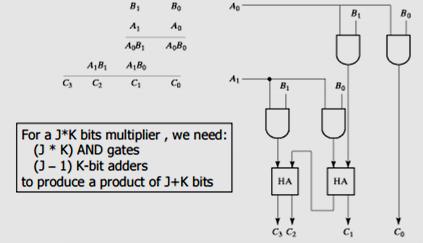
35 inary Multiplier

36 4-it y 3-it inary Multiplier


37 Decoders Etract Information from the code inary Decoder Eample: 2-bit inary Number Only one lamp will turn on inary Decoder
38 inary Decoder Decoders 2-to-4 Line Decoder Y 3 I I y 3 y 2 y y Y 2 Y Y I I Y 3 Y 2 Y Y I I Y3 I I Y2 I I Y I I Y I I
39 inary Decoder Decoders 3-to-8 Line Decoder Y 7 Y 6 I I 2 I I 2 I I I 2 I I Y 7 Y 6 Y 5 Y 4 Y 3 Y 2 Y Y Y 5 Y 4 Y 3 Y 2 Y Y I I I I I I 2 I I 2 I I 2 I I 2 I I 2 I I 2 I I I 2 I I
40 inary Decoder Decoders Enable ontrol Y 3 I I E Y 3 Y 2 Y Y Y 2 Y Y E I I Y 3 Y 2 Y Y I I E
41 Decoders inary Decoder inary Decoder Epansion I 2 I I I 2 I I Y 7 Y 6 Y 5 Y 4 Y 3 Y 2 Y Y I I E I I E Y 3 Y 2 Y Y Y 3 Y 2 Y Y Y 7 Y 6 Y 5 Y 4 Y 3 Y 2 Y Y
42 inary Decoder Decoders inary Decoder ctive-high / ctive-low I I Y 3 Y 2 Y Y I I Y 3 Y 2 Y Y Y 3 Y 2 I I Y 3 Y 2 Y I Y 3 Y 2 Y Y I I Y I Y Y
43 Implementation Using Decoders Each output is a minterm ll minterms are produced Sum the required minterms Eample: Full dder S(, y, z) = (, 2, 4, 7) (, y, z) = (3, 5, 6, 7) y z inary Decoder I 2 I I Y 7 Y 6 Y 5 Y 4 Y 3 Y 2 Y Y S
44 Implementation Using Decoders inary Decoder inary Decoder y z I 2 I I Y 7 Y 6 Y 5 Y 4 Y 3 Y 2 Y Y y z I 2 I I Y 7 Y 6 Y 5 Y 4 Y 3 Y 2 Y Y S S

45 Seven-Segment Decoder w y z a b c d e f g w y z? D code y w z a b c d a = w + y + z + z b =... c =... d =... e f g e f d a g b c
46 Encoders Put Information into code inary Encoder Eample: 4-to-2 inary Encoder Only one switch should be activated at a time 2 3 inary Encoder y y 3 2 y y
47 Encoders inary Encoder Octal-to-inary Encoder (8-to-3) I 7 I 6 I 5 I 4 I 3 I 2 I I Y 2 Y Y Y Y Y 2 I I I I I I I I I I I I 4 2 I 7 I 6 I 5 I 4 I 3 I 2 I I I 7 I 6 I 5 I 4 I 3 I 2 I I Y 2 Y Y Y 2 Y Y
48 Priority Encoders Priority Encoder 4-Input Priority Encoder I 3 I 2 I I Y Y V I 3 I 2 I 3 I 2 I I V Y Y Y Y I I 3 I I 2 Y Y V I I I I I I I I I I I Y V
49 Encoder / Decoder Pairs inary Encoder inary Decoder I 7 I 6 I 5 I 4 I 3 I 2 I I Y 2 Y Y I 2 I I Y 7 Y 6 Y 5 Y 4 Y 3 Y 2 Y Y
50 Digital Multipleer S S Y I I I I I 2 MUX I 3 S S Y I 2 I 3
51 Multipleers 2-to- MUX I I I MUX S Y I Y S 4-to- MUX I I I I I 2 MUX I 3 S S Y I 2 I 3 Y S S
52 Multipleers Quad 2-to- MUX 3 y 3 I I MUX Y S 3 2 Y 3 Y 2 Y Y 2 y 2 y y I I I I I I MUX Y S MUX Y S MUX Y S 3 2 S E MUX S E Y 3 Y 2 Y Y S
53 Multipleers Quad 2-to- MUX Y 3 Y 2 Y Y MUX S E Y 3 Y 2 Y Y Etra uffers S E
54 Implementation Using Multipleers Eample F(, y) = (,, 3) y F I I I 2 MUX I 3 S S y Y F
55 Implementation Using Using Multipleers Eample F(, y, z) = (, 2, 6, 7) y z F I I I 2 I 3 I MUX 4 I 5 I 6 I 7 S2 S S y z Y F
56 Implementation Using Using Multipleers Eample F(, y, z) = (, 2, 6, 7) y z F F = z F = z F = F = z z I I I 2 MUX I 3 S S y Y F
57 Implementation Using Using Multipleers Eample F(,,, D) = (, 3, 4,, 2, 3, 4, 5) D F F = D F = D F = D F = F = F = D F = F = D D D D I I I 2 I 3 I MUX 4 I 5 I 6 I 7 S2 S S Y F
58 Multipleer Epansion 8-to- MUX using Dual 4-to- MUX I I I 2 I 3 I I I 2 MUX I 3 S S Y I 4 I 5 I 6 I 7 I I I 2 MUX I 3 S S Y I I MUX S Y Y S 2 S S
59 DeMultipleers I DeMUX S S Y 3 Y 2 Y Y Y 3 I S S Y 2 Y Y S S Y 3 Y 2 Y Y I I I I
60 Multipleer / DeMultipleers Pairs MUX DeMUX I 7 I 6 I 5 I 4 I 3 I 2 I I Y I Y 7 Y 6 Y 5 Y 4 Y 3 Y 2 Y Y S 2 S S S 2 S S Synchronize 2 y 2 y y
61 DeMultipleers / Decoders inary Decoder I DeMUX S S Y 3 Y 2 Y Y I I E Y 3 Y 2 Y Y S S Y 3 Y 2 Y Y I I I I E I I Y 3 Y 2 Y Y
62 Magnitude omparator ompare 4-bit number to 4-bit number 3 Outputs: <, =, > Epandable to more number of bits Magnitude omparator < = > ) ( ) ( ) (
63 Magnitude omparator (<) (>) (=)
64 Magnitude omparator y 7 y 6 y 5 y y 3 y 2 y y I (>) I (=) I (<) Magnitude omparator < = > I (>) I (=) I (<) Magnitude omparator < = > < = >
65 Thank you
Combinational Logic. Jee-Hwan Ryu. School of Mechanical Engineering Korea University of Technology and Education
 MEC5 디지털공학 Combinational Logic Jee-Hwan Ryu School of Mechanical Engineering Combinational circuits Outputs are determined from the present inputs Consist of input/output variables and logic gates inary
Fundamentals of Computer Systems
 Fundamentals of omputer Systems ombinational Logic Stephen. Edwards olumbia University Fall 2012 Encoders and Decoders Decoders Input: n-bit binary number Output: 1-of-2 n one-hot code 2-to-4 in out 00
CMSC 313 Lecture 18 Midterm Exam returned Assign Homework 3 Circuits for Addition Digital Logic Components Programmable Logic Arrays
 CMSC 33 Lecture 8 Midterm Exam returned ssign Homework 3 Circuits for ddition Digital Logic Components Programmable Logic rrays UMC, CMSC33, Richard Chang Half dder Inputs: and Outputs:
Chapter 4. Combinational: Circuits with logic gates whose outputs depend on the present combination of the inputs. elements. Dr.
 Chapter 4 Dr. Panos Nasiopoulos Combinational: Circuits with logic gates whose outputs depend on the present combination of the inputs. Sequential: In addition, they include storage elements Combinational
Chapter 4: Combinational Logic Solutions to Problems: [1, 5, 9, 12, 19, 23, 30, 33]
![Chapter 4: Combinational Logic Solutions to Problems: [1, 5, 9, 12, 19, 23, 30, 33]](/thumbs/81/84077758.jpg "Chapter 4: Combinational Logic Solutions to Problems: [1, 5, 9, 12, 19, 23, 30, 33]") Chapter 4: Combinational Logic Solutions to Problems: [, 5, 9, 2, 9, 23, 3, 33] Problem: 4- Consider the combinational circuit shown in Fig. P4-. (a) Derive the Boolean expressions for T through T 4. Evaluate
Chapter 4: Combinational Logic Solutions to Problems: [, 5, 9, 2, 9, 23, 3, 33] Problem: 4- Consider the combinational circuit shown in Fig. P4-. (a) Derive the Boolean expressions for T through T 4. Evaluate
Appendix A: Digital Logic. Principles of Computer Architecture. Principles of Computer Architecture by M. Murdocca and V. Heuring
 - Principles of Computer rchitecture Miles Murdocca and Vincent Heuring 999 M. Murdocca and V. Heuring -2 Chapter Contents. Introduction.2 Combinational Logic.3 Truth Tables.4 Logic Gates.5 Properties
Logic. Basic Logic Functions. Switches in series (AND) Truth Tables. Switches in Parallel (OR) Alternative view for OR
 Truth Tables. Switches in Parallel (OR) Alternative view for OR") TOPIS: Logic Logic Expressions Logic Gates Simplifying Logic Expressions Sequential Logic (Logic with a Memory) George oole (85-864), English mathematician, oolean logic used in digital computers since
TOPIS: Logic Logic Expressions Logic Gates Simplifying Logic Expressions Sequential Logic (Logic with a Memory) George oole (85-864), English mathematician, oolean logic used in digital computers since
Carry Look Ahead Adders
 Carry Look Ahead Adders Lesson Objectives: The objectives of this lesson are to learn about: 1. Carry Look Ahead Adder circuit. 2. Binary Parallel Adder/Subtractor circuit. 3. BCD adder circuit. 4. Binary
COMP2611: Computer Organization. Introduction to Digital Logic
 1 OMP2611: omputer Organization ombinational Logic OMP2611 Fall 2015 asics of Logic ircuits 2 its are the basis for binary number representation in digital computers ombining bits into patterns following
S.E. Sem. III [ETRX] Digital Circuit Design. t phl. Fig.: Input and output voltage waveforms to define propagation delay times.
![S.E. Sem. III [ETRX] Digital Circuit Design. t phl. Fig.: Input and output voltage waveforms to define propagation delay times.](/thumbs/93/111090909.jpg "S.E. Sem. III [ETRX] Digital Circuit Design. t phl. Fig.: Input and output voltage waveforms to define propagation delay times.") S.E. Sem. III [ETRX] Digital ircuit Design Time : 3 Hrs.] Prelim Paper Solution [Marks : 80. Solve following : [20].(a) Explain characteristics of logic families. [5] haracteristics of logic families are
S.E. Sem. III [ETRX] Digital ircuit Design Time : 3 Hrs.] Prelim Paper Solution [Marks : 80. Solve following : [20].(a) Explain characteristics of logic families. [5] haracteristics of logic families are
Systems I: Computer Organization and Architecture
 Systems I: Computer Organization and Architecture Lecture 6 - Combinational Logic Introduction A combinational circuit consists of input variables, logic gates, and output variables. The logic gates accept
Show that the dual of the exclusive-or is equal to its compliment. 7
 Darshan Institute of ngineering and Technology, Rajkot, Subject: Digital lectronics (2300) GTU Question ank Unit Group Questions Do as directed : I. Given that (6)0 = (00)x, find the value of x. II. dd
COMBINATIONAL LOGIC CIRCUITS. Dr. Mudathir A. Fagiri
 COMBINATIONAL LOGIC CIRCUITS Dr. Mudathir A. Fagiri Standard Combinational Modules Decoder: Decode address Encoder: Encode address Multiplexer (Mux): Select data by address Demultiplexier (DeMux): Direct
Logic. Combinational. inputs. outputs. the result. system can
 Digital Electronics Combinational Logic Functions Digital logic circuits can be classified as either combinational or sequential circuits. A combinational circuit is one where the output at any time depends
COMBINATIONAL CIRCUITS
 OMINTIONL IRUITS pplications Parity Generation and heking Even Parity P e P e P P P P P P5 P P6 ( ) = m(,, ) =, Odd Parity P o P e Three-bit Parity Generator ( ) = m(,,5, ) P P P P P P5 P P6 = 6 Three-bit
Combina-onal Logic Chapter 4. Topics. Combina-on Circuit 10/13/10. EECE 256 Dr. Sidney Fels Steven Oldridge
 Combina-onal Logic Chapter 4 EECE 256 Dr. Sidney Fels Steven Oldridge Topics Combina-onal circuits Combina-onal analysis Design procedure simple combined to make complex adders, subtractors, converters
COMBINATIONAL LOGIC FUNCTIONS
 COMBINATIONAL LOGIC FUNCTIONS Digital logic circuits can be classified as either combinational or sequential circuits. A combinational circuit is one where the output at any time depends only on the present
Combinational Logic. By : Ali Mustafa
 Combinational Logic By : Ali Mustafa Contents Adder Subtractor Multiplier Comparator Decoder Encoder Multiplexer How to Analyze any combinational circuit like this? Analysis Procedure To obtain the output
Arithmetic Circuits How to add and subtract using combinational logic Setting flags Adding faster
 rithmetic Circuits Didn t I learn how to do addition in second grade? UNC courses aren t what they used to be... 01011 +00101 10000 Finally; time to build some serious functional blocks We ll need a lot
EECS150. Arithmetic Circuits
 EE5 ection 8 Arithmetic ircuits Fall 2 Arithmetic ircuits Excellent Examples of ombinational Logic Design Time vs. pace Trade-offs Doing things fast may require more logic and thus more space Example:
Switching Circuits & Logic Design
 Switching ircuits & Logic esign Jieong Roland Jiang 江介宏 epartment of lectrical ngineering National Taiwan University Fall 22 6 Sequential ircuit esign homsky ierarchy http://www.cs.lmu.edu/~ray/notes/languagetheory/
Why digital? Overview. Number Systems. Binary to Decimal conversion
 Why digital? Overview It has the following advantages over analog. It can be processed and transmitted efficiently and reliably. It can be stored and retrieved with greater accuracy. Noise level does not
ELCT201: DIGITAL LOGIC DESIGN
 ELCT201: DIGITAL LOGIC DESIGN Dr. Eng. Haitham Omran, haitham.omran@guc.edu.eg Dr. Eng. Wassim Alexan, wassim.joseph@guc.edu.eg Lecture 5 Following the slides of Dr. Ahmed H. Madian ذو الحجة 1438 ه Winter
We are here. Assembly Language. Processors Arithmetic Logic Units. Finite State Machines. Circuits Gates. Transistors
 CSC258 Week 3 1 Logistics If you cannot login to MarkUs, email me your UTORID and name. Check lab marks on MarkUs, if it s recorded wrong, contact Larry within a week after the lab. Quiz 1 average: 86%
Chapter 2. Review of Digital Systems Design
 x 2-4 = 42.625. Chapter 2 Review of Digital Systems Design Numbering Systems Decimal number may be expressed as powers of 10. For example, consider a six digit decimal number 987654, which can be represented
Theory of Logic Circuits. Laboratory manual. Exercise 1
 Zakład Mikroinformatyki i Teorii utomatów Cyfrowych Theory of Logic Circuits Laboratory manual Eercise Combinational switching circuits 008 Urszula Stańczyk, Piotr Czekalski (edt. E.. Combinational switching
CMSC 313 Lecture 18 Midterm Exam returned Assign Homework 3 Circuits for Addition Digital Logic Components Programmable Logic Arrays
 MS 33 Lecture 8 Midterm Exam returned Assign Homework 3 ircuits for Addition Digital Logic omponents Programmable Logic Arrays UMB, MS33, Richard hang MS 33, omputer Organization & Assembly
Number System. Decimal to binary Binary to Decimal Binary to octal Binary to hexadecimal Hexadecimal to binary Octal to binary
 Number System Decimal to binary Binary to Decimal Binary to octal Binary to hexadecimal Hexadecimal to binary Octal to binary BOOLEAN ALGEBRA BOOLEAN LOGIC OPERATIONS Logical AND Logical OR Logical COMPLEMENTATION
Module 2. Basic Digital Building Blocks. Binary Arithmetic & Arithmetic Circuits Comparators, Decoders, Encoders, Multiplexors Flip-Flops
 Module 2 asic Digital uilding locks Lecturer: Dr. Yongsheng Gao Office: Tech 3.25 Email: Web: Structure: Textbook: yongsheng.gao@griffith.edu.au maxwell.me.gu.edu.au 6 lecturers 1 tutorial 1 laboratory
SIR C.R.REDDY COLLEGE OF ENGINEERING ELURU DIGITAL INTEGRATED CIRCUITS (DIC) LABORATORY MANUAL III / IV B.E. (ECE) : I - SEMESTER
 LABORATORY MANUAL III / IV B.E. (ECE) : I - SEMESTER") SIR C.R.REDDY COLLEGE OF ENGINEERING ELURU 534 007 DIGITAL INTEGRATED CIRCUITS (DIC) LABORATORY MANUAL III / IV B.E. (ECE) : I - SEMESTER DEPARTMENT OF ELECTRONICS AND COMMUNICATION ENGINEERING DIGITAL
SIR C.R.REDDY COLLEGE OF ENGINEERING ELURU 534 007 DIGITAL INTEGRATED CIRCUITS (DIC) LABORATORY MANUAL III / IV B.E. (ECE) : I - SEMESTER DEPARTMENT OF ELECTRONICS AND COMMUNICATION ENGINEERING DIGITAL
Digital Electronics Circuits 2017
 JSS SCIENCE AND TECHNOLOGY UNIVERSITY Digital Electronics Circuits (EC37L) Lab in-charge: Dr. Shankraiah Course outcomes: After the completion of laboratory the student will be able to, 1. Simplify, design
Full Adder Ripple Carry Adder Carry-Look-Ahead Adder Manchester Adders Carry Select Adder
 Outline E 66 U Resources: dders & Multipliers Full dder Ripple arry dder arry-look-head dder Manchester dders arry Select dder arry Skip dder onditional Sum dder Hybrid Designs leksandar Milenkovic E-mail:
Digital System Design Combinational Logic. Assoc. Prof. Pradondet Nilagupta
 Digital System Design Combinational Logic Assoc. Prof. Pradondet Nilagupta pom@ku.ac.th Acknowledgement This lecture note is modified from Engin112: Digital Design by Prof. Maciej Ciesielski, Prof. Tilman
Overview. Arithmetic circuits. Binary half adder. Binary full adder. Last lecture PLDs ROMs Tristates Design examples
 Overview rithmetic circuits Last lecture PLDs ROMs Tristates Design examples Today dders Ripple-carry Carry-lookahead Carry-select The conclusion of combinational logic!!! General-purpose building blocks
Combinational Logic. Mantıksal Tasarım BBM231. section instructor: Ufuk Çelikcan
 Combinational Logic Mantıksal Tasarım BBM23 section instructor: Ufuk Çelikcan Classification. Combinational no memory outputs depends on only the present inputs expressed by Boolean functions 2. Sequential
Digital- or Logic Circuits. Outline Logic Circuits. Logic Voltage Levels. Binary Representation
 Outline Logic ircuits Introduction Logic Systems TTL MOS Logic Gates NOT, OR, N NOR, NN, XOR Implementation oolean lgebra ombinatorial ircuits Multipleer emultipleer rithmetic ircuits Simplifying Logic
Review. EECS Components and Design Techniques for Digital Systems. Lec 18 Arithmetic II (Multiplication) Computer Number Systems
 Computer Number Systems") Review EE 5 - omponents and Design Techniques for Digital ystems Lec 8 rithmetic II (Multiplication) David uller Electrical Engineering and omputer ciences University of alifornia, Berkeley http://www.eecs.berkeley.edu/~culler
Review EE 5 - omponents and Design Techniques for Digital ystems Lec 8 rithmetic II (Multiplication) David uller Electrical Engineering and omputer ciences University of alifornia, Berkeley http://www.eecs.berkeley.edu/~culler
DESIGN AND IMPLEMENTATION OF ENCODERS AND DECODERS. To design and implement encoders and decoders using logic gates.
 DESIGN AND IMPLEMENTATION OF ENCODERS AND DECODERS AIM To design and implement encoders and decoders using logic gates. COMPONENTS REQUIRED S.No Components Specification Quantity 1. Digital IC Trainer
ELEN Electronique numérique
 ELEN0040 - Electronique numérique Patricia ROUSSEAUX Année académique 2014-2015 CHAPITRE 3 Combinational Logic Circuits ELEN0040 3-4 1 Combinational Functional Blocks 1.1 Rudimentary Functions 1.2 Functions
CSE 140L Spring 2010 Lab 1 Assignment Due beginning of the class on 14 th April
 CSE 140L Spring 2010 Lab 1 Assignment Due beginning of the class on 14 th April Objective - Get familiar with the Xilinx ISE webpack tool - Learn how to design basic combinational digital components -
Learning Objectives. Boolean Algebra. In this chapter you will learn about:
 Ref. Page Slide /78 Learning Objectives In this chapter you will learn about: oolean algebra Fundamental concepts and basic laws of oolean algebra oolean function and minimization Logic gates Logic circuits
211: Computer Architecture Summer 2016
 211: Computer Architecture Summer 2016 Liu Liu Topic: Storage Project3 Digital Logic - Storage: Recap - Review: cache hit rate - Project3 - Digital Logic: - truth table => SOP - simplification: Boolean
Logic Design Combinational Circuits. Digital Computer Design
 Logic Design Combinational Circuits Digital Computer Design Topics Combinational Logic Karnaugh Maps Combinational uilding locks Timing 2 Logic Circuit logic circuit is composed of: Inputs Outputs Functional
CMSC 313 Lecture 19 Homework 4 Questions Combinational Logic Components Programmable Logic Arrays Introduction to Circuit Simplification
 CMSC 33 Lecture 9 Homework 4 Questions Combinational Logic Components Programmable Logic rrays Introduction to Circuit Simplification UMC, CMSC33, Richard Chang CMSC 33, Computer Organization
CSE140: Components and Design Techniques for Digital Systems. Logic minimization algorithm summary. Instructor: Mohsen Imani UC San Diego
 CSE4: Components and Design Techniques for Digital Systems Logic minimization algorithm summary Instructor: Mohsen Imani UC San Diego Slides from: Prof.Tajana Simunic Rosing & Dr.Pietro Mercati Definition
CSEE 3827: Fundamentals of Computer Systems. Combinational Circuits
 CSEE 3827: Fundamentals of Computer Systems Combinational Circuits Outline (M&K 3., 3.3, 3.6-3.9, 4.-4.2, 4.5, 9.4) Combinational Circuit Design Standard combinational circuits enabler decoder encoder
COMPUTERS ORGANIZATION 2ND YEAR COMPUTE SCIENCE MANAGEMENT ENGINEERING UNIT 3 - ARITMETHIC-LOGIC UNIT JOSÉ GARCÍA RODRÍGUEZ JOSÉ ANTONIO SERRA PÉREZ
 OMUTERS ORGANIZATION 2ND YEAR OMUTE SIENE MANAGEMENT ENGINEERING UNIT 3 - ARITMETHI-LOGI UNIT JOSÉ GARÍA RODRÍGUEZ JOSÉ ANTONIO SERRA ÉREZ Tema 3. La Unidad entral de roceso. A.L.U. Arithmetic Logic Unit
Z = F(X) Combinational circuit. A combinational circuit can be specified either by a truth table. Truth Table
 Combinational circuit. A combinational circuit can be specified either by a truth table. Truth Table") Lesson Objectives In this lesson, you will learn about What are combinational circuits Design procedure of combinational circuits Examples of combinational circuit design Combinational Circuits Logic circuit
Lesson Objectives In this lesson, you will learn about What are combinational circuits Design procedure of combinational circuits Examples of combinational circuit design Combinational Circuits Logic circuit
COSC3330 Computer Architecture Lecture 2. Combinational Logic
 COSC333 Computer rchitecture Lecture 2. Combinational Logic Instructor: Weidong Shi (Larry), PhD Computer Science Department University of Houston Today Combinational Logic oolean lgebra Mux, DeMux, Decoder
ECE 2300 Digital Logic & Computer Organization
 ECE 2300 Digital Logic & Computer Organization pring 201 More inary rithmetic LU 1 nnouncements Lab 4 prelab () due tomorrow Lab 5 to be released tonight 2 Example: Fixed ize 2 C ddition White stone =
UNIT II COMBINATIONAL CIRCUITS:
 UNIT II COMBINATIONAL CIRCUITS: INTRODUCTION: The digital system consists of two types of circuits, namely (i) (ii) Combinational circuits Sequential circuits Combinational circuit consists of logic gates
CMSC 313 Lecture 19 Combinational Logic Components Programmable Logic Arrays Karnaugh Maps
 CMSC 33 Lecture 9 Combinational Logic Components Programmable Logic rrays Karnaugh Maps UMC, CMSC33, Richard Chang Last Time & efore Returned midterm exam Half adders & full adders Ripple
Logic and Computer Design Fundamentals. Chapter 5 Arithmetic Functions and Circuits
 Logic and Computer Design Fundamentals Chapter 5 Arithmetic Functions and Circuits Arithmetic functions Operate on binary vectors Use the same subfunction in each bit position Can design functional block
Logic and Computer Design Fundamentals. Chapter 2 Combinational Logic Circuits. Part 2 Circuit Optimization
 Logic and omputer Design Fundamentals hapter 2 ombinational Logic ircuits Part 2 ircuit Optimization harles Kime & Thomas Kaminski 2008 Pearson Education, Inc. (Hyperlinks are active in View Show mode)
Numbers and Arithmetic
 Numbers and Arithmetic See: P&H Chapter 2.4 2.6, 3.2, C.5 C.6 Hakim Weatherspoon CS 3410, Spring 2013 Computer Science Cornell University Big Picture: Building a Processor memory inst register file alu
Function of Combinational Logic ENT263
 Function of Combinational Logic ENT263 Chapter Objectives Distinguish between half-adder and full-adder Use BCD-to-7-segment decoders in display systems Apply multiplexer in data selection Use decoders
DE58/DC58 LOGIC DESIGN DEC 2014
 Q.2 a. In a base-5 number system, 3 digit representations is used. Find out (i) Number of distinct quantities that can be represented.(ii) Representation of highest decimal number in base-5. Since, r=5
Hakim Weatherspoon CS 3410 Computer Science Cornell University
 Hakim Weatherspoon CS 3410 Computer Science Cornell University The slides are the product of many rounds of teaching CS 3410 by Professors Weatherspoon, Bala, Bracy, and Sirer. memory inst 32 register
Combinational Logic. Lan-Da Van ( 范倫達 ), Ph. D. Department of Computer Science National Chiao Tung University Taiwan, R.O.C.
, Ph. D. Department of Computer Science National Chiao Tung University Taiwan, R.O.C.") Combinational Logic ( 范倫達 ), Ph. D. Department of Computer Science National Chiao Tung University Taiwan, R.O.C. Fall, 2010 ldvan@cs.nctu.edu.tw http://www.cs.nctu.edu.tw/~ldvan/ Combinational Circuits
Combinational Logic ( 范倫達 ), Ph. D. Department of Computer Science National Chiao Tung University Taiwan, R.O.C. Fall, 2010 ldvan@cs.nctu.edu.tw http://www.cs.nctu.edu.tw/~ldvan/ Combinational Circuits
Sample Test Paper - I
 Scheme G Sample Test Paper - I Course Name : Computer Engineering Group Marks : 25 Hours: 1 Hrs. Q.1) Attempt any THREE: 09 Marks a) Define i) Propagation delay ii) Fan-in iii) Fan-out b) Convert the following:
Possible logic functions of two variables
 ombinational logic asic logic oolean algebra, proofs by re-writing, proofs by perfect induction logic functions, truth tables, and switches NOT, ND, OR, NND, NOR, OR,..., minimal set Logic realization
CHAPTER1: Digital Logic Circuits Combination Circuits
 CS224: Computer Organization S.KHABET CHAPTER1: Digital Logic Circuits Combination Circuits 1 PRIMITIVE LOGIC GATES Each of our basic operations can be implemented in hardware using a primitive logic gate.
S.Y. Diploma : Sem. III [CO/CM/IF/CD/CW] Digital Techniques s complement 2 s complement 1 s complement
![S.Y. Diploma : Sem. III [CO/CM/IF/CD/CW] Digital Techniques s complement 2 s complement 1 s complement](/thumbs/80/82077570.jpg "S.Y. Diploma : Sem. III [CO/CM/IF/CD/CW] Digital Techniques s complement 2 s complement 1 s complement") S.Y. Diploma : Sem. III [CO/CM/IF/CD/CW] Digital Techniques Time: 3 Hrs.] Prelim Question Paper Solution [Marks : Q.(a) (i) () (2) s COMPLEMENT s COMPLEMENT 2s COMPLEMENT 2s COMPLEMENT + Q.(a) (ii) ()
S.Y. Diploma : Sem. III [CO/CM/IF/CD/CW] Digital Techniques Time: 3 Hrs.] Prelim Question Paper Solution [Marks : Q.(a) (i) () (2) s COMPLEMENT s COMPLEMENT 2s COMPLEMENT 2s COMPLEMENT + Q.(a) (ii) ()
Simlification of Switching Functions
 Simlification of Switching unctions ( ) = ( 789 5) Quine-Mc luskey Original nonminimized oolean function m i m i m n m i [] m m m m m 4 m 5 m 6 m 7 m 8 m 9 m m m m m 4 m 5 m m m 7 m 8 m 9 m m 5 The number
Decoding A Counter. svbitec.wordpress.com 1
 ecoding A ounter ecoding a counter involves determining which state in the sequence the counter is in. ifferentiate between active-high and active-low decoding. Active-HIGH decoding: output HIGH if the
Addition and Subtraction
 ddition and Subtraction Philipp Koehn 9 February 2018 1 addition 1-it dder 2 Let s start simple: dding two 1-it numbers Truth table + 0 0 0 0 1 1 1 0 1 1 1 10 Really 2 Operations 3 Truth table for "position
Arithmetic Circuits-2
 Arithmetic ircuits-2 Multipliers Array multipliers hifters Barrel shifter Logarithmic shifter EE 261 Krish hakrabarty 1 Binary Multiplication X = Σ X i 2 i i=0 Multiplicand M-1 N-1 Y = Σ Y i 2 i i=0 Multiplier
Combinational Logic (mostly review!)
") ombinational Logic (mostly review!)! Logic functions, truth tables, and switches " NOT, N, OR, NN, NOR, OR,... " Minimal set! xioms and theorems of oolean algebra " Proofs by re-writing " Proofs by perfect
ombinational Logic (mostly review!)! Logic functions, truth tables, and switches " NOT, N, OR, NN, NOR, OR,... " Minimal set! xioms and theorems of oolean algebra " Proofs by re-writing " Proofs by perfect
Chapter 2. Introduction. Chapter 2 :: Topics. Circuits. Nodes. Circuit elements. Introduction
 hapter 2 Introduction igital esign and omputer rchitecture, 2 nd Edition avid Money Harris and Sarah L. Harris logic circuit is composed of: Inputs Outputs Functional specification Timing specification
Combinational Logic Design Arithmetic Functions and Circuits
 Combinational Logic Design Arithmetic Functions and Circuits Overview Binary Addition Half Adder Full Adder Ripple Carry Adder Carry Look-ahead Adder Binary Subtraction Binary Subtractor Binary Adder-Subtractor
Lecture 2 Review on Digital Logic (Part 1)
") Lecture 2 Review on Digital Logic (Part 1) Xuan Silvia Zhang Washington University in St. Louis http://classes.engineering.wustl.edu/ese461/ Grading Engagement 5% Review Quiz 10% Homework 10% Labs 40%
Lecture 2 Review on Digital Logic (Part 1) Xuan Silvia Zhang Washington University in St. Louis http://classes.engineering.wustl.edu/ese461/ Grading Engagement 5% Review Quiz 10% Homework 10% Labs 40%
Design of Combinational Logic
 Pune Vidyarthi Griha s COLLEGE OF ENGINEERING, NASHIK 3. Design of Combinational Logic By Prof. Anand N. Gharu (Assistant Professor) PVGCOE Computer Dept.. 30 th June 2017 CONTENTS :- 1. Code Converter
PG - TRB UNIT-X- DIGITAL ELECTRONICS. POLYTECHNIC-TRB MATERIALS
 SRIMAAN COACHING CENTRE-PG-TRB-PHYSICS- DIGITAL ELECTRONICS-STUDY MATERIAL-CONTACT: 8072230063 SRIMAAN PG - TRB PHYSICS UNIT-X- DIGITAL ELECTRONICS POLYTECHNIC-TRB MATERIALS MATHS/COMPUTER SCIENCE/IT/ECE/EEE
Fundamentals of Digital Design
 Fundamentals of Digital Design Digital Radiation Measurement and Spectroscopy NE/RHP 537 1 Binary Number System The binary numeral system, or base-2 number system, is a numeral system that represents numeric
IT T35 Digital system desigm y - ii /s - iii
 UNIT - II Combinational Logic Adders subtractors code converters binary parallel adder decimal adder magnitude comparator encoders decoders multiplexers demultiplexers-binarymultiplier Parity generator
Reg. No. Question Paper Code : B.E./B.Tech. DEGREE EXAMINATION, NOVEMBER/DECEMBER Second Semester. Computer Science and Engineering
 Sp 6 Reg. No. Question Paper Code : 27156 B.E./B.Tech. DEGREE EXAMINATION, NOVEMBER/DECEMBER 2015. Second Semester Computer Science and Engineering CS 6201 DIGITAL PRINCIPLES AND SYSTEM DESIGN (Common
WORKBOOK. Try Yourself Questions. Electrical Engineering Digital Electronics. Detailed Explanations of
 27 WORKBOOK Detailed Eplanations of Try Yourself Questions Electrical Engineering Digital Electronics Number Systems and Codes T : Solution Converting into decimal number system 2 + 3 + 5 + 8 2 + 4 8 +
ENGIN 112 Intro to Electrical and Computer Engineering
 ENGIN 112 Intro to Electrical and Computer Engineering Lecture 17 Encoders and Decoders Overview Binary decoders Converts an n-bit code to a single active output Can be developed using AND/OR gates Can
University of Toronto Faculty of Applied Science and Engineering Final Examination
 University of Toronto Faculty of Applied Science and Engineering Final Examination ECE 24S - Digital Systems Examiner: Belinda Wang, Jianwen Zhu 2: - 4:3pm, April 26th, 24 Duration: 5 minutes (2.5 hours)
ECE380 Digital Logic. Positional representation
 ECE380 Digital Logic Number Representation and Arithmetic Circuits: Number Representation and Unsigned Addition Dr. D. J. Jackson Lecture 16-1 Positional representation First consider integers Begin with
CSE140: Components and Design Techniques for Digital Systems. Decoders, adders, comparators, multipliers and other ALU elements. Tajana Simunic Rosing
 CSE4: Components and Design Techniques for Digital Systems Decoders, adders, comparators, multipliers and other ALU elements Tajana Simunic Rosing Mux, Demux Encoder, Decoder 2 Transmission Gate: Mux/Tristate
Adders allow computers to add numbers 2-bit ripple-carry adder
 Lecture 12 Logistics HW was due yesterday HW5 was out yesterday (due next Wednesday) Feedback: thank you! Things to work on: ig picture, ook chapters, Exam comments Last lecture dders Today Clarification
Appendix A: Digital Logic. CPSC 352- Computer Organization
 - CPSC 352- Computer Organization -2 Chapter Contents. Introduction.2 Combinational Logic.3 Truth Tables.4 Logic Gates.5 Properties of oolean lgebra.6 The Sum-of-Products Form, and Logic Diagrams.7 The
CPE100: Digital Logic Design I
 Professor Brendan Morris, SEB 3216, brendan.morris@unlv.edu CPE100: Digital Logic Design I Final Review http://www.ee.unlv.edu/~b1morris/cpe100/ 2 Logistics Tuesday Dec 12 th 13:00-15:00 (1-3pm) 2 hour
A B D 1 Y D 2 D 3. Truth table for 4 to 1 MUX: A B Y 0 0 D D D D 3
 . What is a multiplexer? esign a 4 to multiplexer using logic gates. Write the truth table and explain its working principle. Answer: is a circuit with many inputs but only one output. esigning of 4 to
Adders, subtractors comparators, multipliers and other ALU elements
 CSE4: Components and Design Techniques for Digital Systems Adders, subtractors comparators, multipliers and other ALU elements Instructor: Mohsen Imani UC San Diego Slides from: Prof.Tajana Simunic Rosing
ว ตถ ประสงค ของบทเร ยน
 Logic Design with MSI Circuits ว ตถ ประสงค ของบทเร ยน ร จ กวงจรประเภท MSI เข าใจการทำงานของวงจร MSI ท ม ใช อย ท วไป สามารถประย กต ใช วงจร MSI ในการออกแบบวงจรลอจ กแบบต างๆ ได A. Yaicharoen 1 Type of Circuits
Binary addition (1-bit) P Q Y = P + Q Comments Carry = Carry = Carry = Carry = 1 P Q
 P Q Y = P + Q Comments Carry = Carry = Carry = Carry = 1 P Q") Digital Arithmetic In Chapter 2, we have discussed number systems such as binary, hexadecimal, decimal, and octal. We have also discussed sign representation techniques, for example, sign-bit representation
Digital Arithmetic In Chapter 2, we have discussed number systems such as binary, hexadecimal, decimal, and octal. We have also discussed sign representation techniques, for example, sign-bit representation
Adders, subtractors comparators, multipliers and other ALU elements
 CSE4: Components and Design Techniques for Digital Systems Adders, subtractors comparators, multipliers and other ALU elements Adders 2 Circuit Delay Transistors have instrinsic resistance and capacitance
Numbers and Arithmetic
 Numbers and Arithmetic See: P&H Chapter 2.4 2.6, 3.2, C.5 C.6 Hakim Weatherspoon CS 3410, Spring 2013 Computer Science Cornell University Big Picture: Building a Processor memory inst register file alu
CSE 140 Lecture 11 Standard Combinational Modules. CK Cheng and Diba Mirza CSE Dept. UC San Diego
 CSE 4 Lecture Standard Combinational Modules CK Cheng and Diba Mirza CSE Dept. UC San Diego Part III - Standard Combinational Modules (Harris: 2.8, 5) Signal Transport Decoder: Decode address Encoder:
Combinational Logic. Lan-Da Van ( 范倫達 ), Ph. D. Department of Computer Science National Chiao Tung University Taiwan, R.O.C.
, Ph. D. Department of Computer Science National Chiao Tung University Taiwan, R.O.C.") Combinational Logic ( 范倫達 ), Ph. D. Department of Computer Science National Chiao Tung University Taiwan, R.O.C. Fall, 2017 ldvan@cs.nctu.edu.tw http://www.cs.nctu.edu.tw/~ldvan/ Combinational Circuits
Combinational Logic ( 范倫達 ), Ph. D. Department of Computer Science National Chiao Tung University Taiwan, R.O.C. Fall, 2017 ldvan@cs.nctu.edu.tw http://www.cs.nctu.edu.tw/~ldvan/ Combinational Circuits
Review for Test 1 : Ch1 5
 Review for Test 1 : Ch1 5 October 5, 2006 Typeset by FoilTEX Positional Numbers 527.46 10 = (5 10 2 )+(2 10 1 )+(7 10 0 )+(4 10 1 )+(6 10 2 ) 527.46 8 = (5 8 2 ) + (2 8 1 ) + (7 8 0 ) + (4 8 1 ) + (6 8
Appendix A: Digital Logic. Principles of Computer Architecture. Principles of Computer Architecture by M. Murdocca and V. Heuring
 - Principles of Computer rchitecture Miles Murdocca and Vincent Heuring 999 M. Murdocca and V. Heuring -2 Chapter Contents. Introduction.2 Combinational Logic.3 Truth Tables.4 Logic Gates.5 Properties
KUMARAGURU COLLEGE OF TECHNOLOGY COIMBATORE
 Estd-1984 KUMARAGURU COLLEGE OF TECHNOLOGY COIMBATORE 641 006 QUESTION BANK UNIT I PART A ISO 9001:2000 Certified 1. Convert (100001110.010) 2 to a decimal number. 2. Find the canonical SOP for the function
CMP 334: Seventh Class
 CMP 334: Seventh Class Performance HW 5 solution Averages and weighted averages (review) Amdahl's law Ripple-carry adder circuits Binary addition Half-adder circuits Full-adder circuits Subtraction, negative
Prove that if not fat and not triangle necessarily means not green then green must be fat or triangle (or both).
.") hapter : oolean lgebra.) Definition of oolean lgebra The oolean algebra is named after George ool who developed this algebra (854) in order to analyze logical problems. n example to such problem is: Prove
hapter : oolean lgebra.) Definition of oolean lgebra The oolean algebra is named after George ool who developed this algebra (854) in order to analyze logical problems. n example to such problem is: Prove
Digital Circuits. 1. Inputs & Outputs are quantized at two levels. 2. Binary arithmetic, only digits are 0 & 1. Position indicates power of 2.
 Digital Circuits 1. Inputs & Outputs are quantized at two levels. 2. inary arithmetic, only digits are 0 & 1. Position indicates power of 2. 11001 = 2 4 + 2 3 + 0 + 0 +2 0 16 + 8 + 0 + 0 + 1 = 25 Digital
Section 3: Combinational Logic Design. Department of Electrical Engineering, University of Waterloo. Combinational Logic
 Section 3: Combinational Logic Design Major Topics Design Procedure Multilevel circuits Design with XOR gates Adders and Subtractors Binary parallel adder Decoders Encoders Multiplexers Programmed Logic
Chapter 2: Princess Sumaya Univ. Computer Engineering Dept.
 hapter 2: Princess Sumaya Univ. omputer Engineering Dept. Basic Definitions Binary Operators AND z = x y = x y z=1 if x=1 AND y=1 OR z = x + y z=1 if x=1 OR y=1 NOT z = x = x z=1 if x=0 Boolean Algebra