Combinational Logic. Lan-Da Van ( 范倫達 ), Ph. D. Department of Computer Science National Chiao Tung University Taiwan, R.O.C.
|
|
|
- Jessie Bradley
- 5 years ago
- Views:
Transcription

1 Combinational Logic ( 范倫達 ), Ph. D. Department of Computer Science National Chiao Tung University Taiwan, R.O.C. Fall, 2010 ldvan@cs.nctu.edu.tw
2 Combinational Circuits Analysis Procedure Design Procedure Binary Adder-Subtractor Decimal Adder Binary Multiplier Decoders Encoders Multiplexers Outlines DCD-04-2
3 Introduction Logic circuits for digital systems may be either combinational or sequential. A combinational circuit consists of logic gates whose outputs at any time are determined from only the present combination of inputs. DCD-04-3
4 Combinational Circuits A combinational circuits 2 n possible combinations of input values n input variables Combinational Logic Circuit m output variables Specific functions Adders, subtractors, comparators, decoders, encoders, and multiplexers MSI circuits or standard cells DCD-04-4
5 Analysis Procedure Step 1: Label all gate outputs that are a function of input variables with arbitrary symbols but with meaningful names. Determine the Boolean functions for each gate output. Step 2: Label the gates that are a function of input variables and previously labeled gates with other arbitrary symbols. Find the Boolean functions for these gates. Step 3: Repeat the process outlined in step 2 until the outputs of the circuit are obtained. Step 4: By repeated substitution of previously defined functions, obtain the output Boolean functions in terms of input variables. DCD-04-5
6 Analysis Procedure Example A straight-forward procedure DCD-04-6
7 Analysis Procedure Example Step 1: F 2 = AB+AC+BC T 1 = A+B+C T 2 = ABC Step 2: T3 = F 2 'T 1 Step 3: F1 = T 3 +T 2 Step 4: F 1 = T 3 +T 2 = F 2 'T 1 +ABC = (AB+AC+BC)'(A+B+C)+ABC = (A'+B')(A'+C')(B'+C')(A+B+C)+ABC = (A'+B'C')(AB'+AC'+BC'+B'C)+ABC = A'BC'+A'B'C+AB'C'+ABC DCD-04-7
8 Truth Table DCD-04-8
9 Design Procedure The design procedure of combinational circuits Step 1: State the problem (system spec.) Step 2: From the specifications of the circuits, determine the required number of inputs and outputs and assign a symbol to each. Step 3: Derive the truth table that defined the required relationship between inputs and outputs Step 4: Obtain the simplified Boolean functions for each output as a function of the input variables. Step 5: Draw the logic diagram and verify the correctness of the design (manually or by simulation). DCD-04-9
10 Design Method and Constraint Functional description Boolean function HDL (Hardware description language) Verilog HDL VHDL Schematic entry Logic constraint number of gates number of inputs to a gate propagation delay number of interconnections limitations of the driving capabilities DCD-04-10
11 BCD to Excess-3 Code Conversion Digital Circuit Design DCD-04-11


12 BCD to Excess-3 Code Conversion Digital Circuit Design DCD-04-12
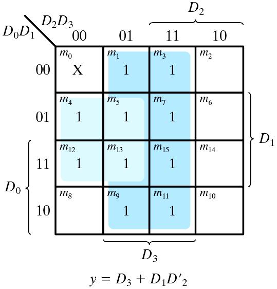
13 BCD to Excess-3 Code Conversion Digital Circuit Design Simplified functions z = D' y = CD +C'D' x = B'C + B'D+BC'D' w = A+BC+BD Efficient implementation z = D' y = CD +C'D'= CD + (C+D) x = B'C + B'D+BC'D = B'(C+D) +B(C+D)' w = A+BC+BD= A+ B(C+D) DCD-04-13
14 Logic Diagram for BCD to Excess-3 Code Converter Digital Circuit Design DCD-04-14
15 1-Bit Half Adder Half adder = 0 ; = 1 ; = 1 ; = (10) 2 two input variables: x, y two output variables: C (carry), S (sum) truth table S = x'y+xy'=x y= (x+y)(x'+y') C = xy= (x'+y')' S' = xy+x'y' S = (C+x'y')' DCD-04-15
16 Logic Diagram of 1-Bit Half Adder Digital Circuit Design DCD-04-16
17 Full-Adder The arithmetic sum of three input bits three input bits x, y: two significant bits z: the carry bit from the previous lower significant bit Two output bits: C, S 1-Bit Full Adder Sum Carry DCD-04-17
18 Logic Diagram of 1-Bit Full Adder Digital Circuit Design DCD-04-18
19 Logic Diagram of 1-Bit Full Adder Digital Circuit Design S = x'y'z+x'yz'+ xy'z'+xyz = x (y z) +x(y z) = x y z C = xy + xz + yz = xy + xyz + xy z + xyz + x yz = xy + z (x y + xy) = xy + z (x y) DCD-04-19

20 4-Bit Full Adder Binary adder DCD-04-20
21 Carry Lookahead Adder (1/7) Given Stage i from a Full Adder, we know that there will be a carry generated when A i = B i = "1", whether or not there is a carry-in. Alternately, there will be a carry propagated if the half-sum is "1" and a carry-in, C i occurs. These two signal conditions are called generate, denoted as G i, and propagate, denoted as P i respectively and are identified in the circuit. G i C i+1 A i B i P i C i S i Source: M. Morris Mano and Charles R. Kime, Logic and Computer Design Fundamentals. DCD-04-21
22 Carry Lookahead Adder (2/7) In the ripple carry adder: G i, P i, and S i are local function to each cell of the adder C i is also local function for each cell In the carry lookahead adder, in order to reduce the length of the carry chain, C i is changed to a more global function spanning multiple cells Defining the equations for the Full Adder in term of the P i and G i : P i = A B G = Ai Bi S = G + P i i i i = Pi Ci Ci+ 1 i i C i Source: M. Morris Mano and Charles R. Kime, Logic and Computer Design Fundamentals. DCD-04-22
23 Carry Lookahead Adder (3/7) C i+1 can be removed from the cells and used to derive a set of carry equations spanning multiple cells. Beginning at the cell 0 with carry in C 0 : C 1 = G 0 + P 0 C 0 C 2 = G 1 + P 1 C 1 = G 1 + P 1 (G 0 + P 0 C 0 ) = G 1 + P 1 G 0 + P 1 P 0 C 0 C 3 = G 2 + P 2 C 2 = G 2 + P 2 (G 1 + P 1 G 0 + P 1 P 0 C 0 ) = G 2 + P 2 G 1 + P 2 P 1 G 0 + P 2 P 1 P 0 C 0 C 4 = G 3 + P 3 C 3 = G 3 + P 3 G 2 + P 3 P 2 G 1 + P 3 P 2 P 1 G 0 + P 3 P 2 P 1 P 0 C 0 Source: M. Morris Mano and Charles R. Kime, Logic and Computer Design Fundamentals. DCD-04-23
24 Carry Lookahead Adder (4/7) DCD-04-24
")
25 Carry Lookahead Adder (5/7) DCD-04-25
26 Carry Lookahead Adder (6/7) CLA GEN Source: M. Morris Mano and Charles R. Kime, Logic and Computer Design Fundamentals. DCD-04-26
27 Carry Lookahead Adder (7/7) This lookahead scheme could be extended to more than four bits; in practice, due to limited gate fan-in, such extension is not feasible. Instead, the concept is extended another level by considering group generate (G 0-3 ) and group propagate (P 0-3 ) functions: G Using these two equations: P = = G P 3 3 P + 2 P P 1 3 P G C4 = G0-3 + P0-3 C0 P 3 P Thus, it is possible to have four 4-bit adders use one of the same carry lookahead circuit to speed up 16-bit addition. 2 G 1 + P 3 P 2 P 1 G C 4 = G 3 + P 3 C 3 = G 3 + P 3 G 2 + P 3 P 2 G 1 + P 3 P 2 P 1 G 0 + P 3 P 2 P 1 P 0 C 0 0 Source: M. Morris Mano and Charles R. Kime, Logic and Computer Design Fundamentals. DCD-04-27
28 4-Bit Adder/Subtractor A-B = A+(2 s complement of B) 4-bit Adder-subtractor M=0, A+B; M=1, A+B +1 DCD-04-28
29 Overflow Discussion Overflow The storage is limited. Add two positive numbers and obtain a negative number Add two negative numbers and obtain a positive number V = 0, no overflow; V = 1, overflow Example: DCD-04-29
30 BCD Adder Add two decimal digits in BCD together with an input carry from a previous stage 9 inputs: two BCD's and one carry-in 5 outputs: one BCD and one carry-out Design approaches Since each input digit does not exceed 9, the output sum cannot be grater than =19, where 1 denotes an input carry. A truth table with 19 entries Use two 4-bit binary full adders Modifications are needed if the binary sum > 9 C = 1 K = 1 Z 8 Z 4 = 1 Z 8 Z 2 = 1 modification: +6 C = K +Z 8 Z 4 + Z 8 Z 2 DCD-04-30
31 Truth Table of BCD Adder DCD-04-31
32 Logic Diagram of BCD Adder BCD BCD BCD DCD-04-32
33 Binary Multiplier DCD-04-33

34 4-Bit by 3-Bit Binary Multiplier DCD-04-34
35 Magnitude Comparator The comparison of two numbers outputs: A>B, A=B, A<B Design Approaches the truth table 2 2n entries - too cumbersome for large n use inherent regularity of the problem reduce design efforts reduce human errors Algorithm -> logic A = A 3 A 2 A 1 A 0 ; B = B 3 B 2 B 1 B 0 A=B if A 3 =B 3, A 2 =B 2, A 1 =B 1 and A 0 =B 0 equality: x i = A i B i +A i 'B i ' (A=B) = x 3 x 2 x 1 x 0 (A>B) = A 3 B 3 '+x 3 A 2 B 2 '+x 3 x 2 A 1 B 1 '+x 3 x 2 x 1 A 0 B 0 ' (A<B) = A 3 'B 3 +x 3 A 2 'B 2 +x 3 x 2 A 1 'B 1 +x 3 x 2 x 1 A 0 'B 0 Implementation x i = (A i B i '+A i 'B i )' DCD-04-35
36 Four-Bit Magnitude Comparator DCD-04-36
37 An n-to-m decoder Decoder a binary code of n bits = 2 n distinct information n input variables; up to 2 n output lines only one output can be active (high) at any time DCD-04-37
38 Three-to-Eight Line Decoder x y z DCD-04-38
39 Demultiplexers Decoder with Enable /Demultiplexer a decoder with an enable input receive information on a single line and transmits it on one of 2 n possible output lines Digital Circuit Design 0 Two-to-four-line decoder with enable input DCD-04-39
40 Decoder with Enable /Demultiplexer Digital Circuit Design DCD-04-40
41 Expansion 4x16 Decoder two 3-to-8 decoder: a 4-to-16 decoder 4 16 decoder constructed with two 3 8 decoders DCD-04-41
=S(1,2,4,7) C(x,y,z)= S(3,5,6,7)")
42 Combinational Logic Implementation Digital Circuit Design Each output = a minterm Use a decoder and an external OR gate to implement any Boolean function of n input variables A full-adder S(x,y,x)=S(1,2,4,7) C(x,y,z)= S(3,5,6,7) DCD-04-42
43 Encoder z = D + D + D + D y = D + D + D + D x = D + D + D + D Lan-Da 7 Van The encoder can be implemented with three OR gates. DCD-04-43
44 Encoder An implementation x=d 4 +D 5 +D 6 +D 7 y=d 2 +D 3 +D 6 +D 7 z=d 1 +D 3 +D 5 +D 7 limitations illegal input: e.g. D 3 =D 6 =1 the output = 111 (¹3 and ¹6) DCD-04-44
45 Priority Encoder Resolve the ambiguity of illegal inputs Only one of the input is encoded D 3 has the highest priority D 0 has the lowest priority X: don't-care conditions V: valid output indicator DCD-04-45

46 Priority Encoder 1 DCD-04-46
47 Priority Encoder x = D + D 2 3 y = D + D D V = D + D + D + D DCD-04-47
48 Multiplexer Select binary information from one of many input lines and direct it to a single output line 2 n input lines, n selection lines and one output line E.g.: 2-to-1-line multiplexer Two-to-one-line multiplexer DCD-04-48
49 4-to-1-Line Multiplexer DCD-04-49
50 Quadruple 2-to-1-Line Multiplexer Digital Circuit Design DCD-04-50
51 Boolean Function Implementation Using MUX MUX: a decoder + an OR gate Digital Circuit Design 2 n -to-1 MUX can implement any Boolean function of n input variable. Procedure: assign an ordering sequence of the input variable the rightmost variable (D) will be used for the input lines assign the remaining n-1 variables to the selection lines w.r.t. their corresponding sequence construct the truth table consider a pair of consecutive minterms starting from m 0 determine the input lines DCD-04-51
 = S(1,2,6,7) Digital Circuit Design")
52 Boolean Function Implementation Using MUX Example: Given F(x,y,z) = S(1,2,6,7) Digital Circuit Design DCD-04-52
 = S(1, 3, 4, 11, 12, 13, 14, 15)")
53 Boolean Function Implementation Using MUX Digital Circuit Design Example: Given F(A, B, C, D) = S(1, 3, 4, 11, 12, 13, 14, 15) DCD-04-53
54 Three-State Gate A multiplexer can be constructed with three-state gates. Output state: 0, 1, and high-impedance (open ckts) DCD-04-54
55 Four-to-One-Line Multiplexer DCD-04-55
56 Conclusion From this lecture, you have learned the follows: Adder/Subtractor Multiplier Decoder Encoder Multiplexer DCD-04-56
Combinational Logic. Lan-Da Van ( 范倫達 ), Ph. D. Department of Computer Science National Chiao Tung University Taiwan, R.O.C.
, Ph. D. Department of Computer Science National Chiao Tung University Taiwan, R.O.C.") Combinational Logic ( 范倫達 ), Ph. D. Department of Computer Science National Chiao Tung University Taiwan, R.O.C. Fall, 2017 ldvan@cs.nctu.edu.tw http://www.cs.nctu.edu.tw/~ldvan/ Combinational Circuits
Combinational Logic ( 范倫達 ), Ph. D. Department of Computer Science National Chiao Tung University Taiwan, R.O.C. Fall, 2017 ldvan@cs.nctu.edu.tw http://www.cs.nctu.edu.tw/~ldvan/ Combinational Circuits
Digital System Design Combinational Logic. Assoc. Prof. Pradondet Nilagupta
 Digital System Design Combinational Logic Assoc. Prof. Pradondet Nilagupta pom@ku.ac.th Acknowledgement This lecture note is modified from Engin112: Digital Design by Prof. Maciej Ciesielski, Prof. Tilman
Chapter 4. Combinational: Circuits with logic gates whose outputs depend on the present combination of the inputs. elements. Dr.
 Chapter 4 Dr. Panos Nasiopoulos Combinational: Circuits with logic gates whose outputs depend on the present combination of the inputs. Sequential: In addition, they include storage elements Combinational
Systems I: Computer Organization and Architecture
 Systems I: Computer Organization and Architecture Lecture 6 - Combinational Logic Introduction A combinational circuit consists of input variables, logic gates, and output variables. The logic gates accept
Combinational Logic. By : Ali Mustafa
 Combinational Logic By : Ali Mustafa Contents Adder Subtractor Multiplier Comparator Decoder Encoder Multiplexer How to Analyze any combinational circuit like this? Analysis Procedure To obtain the output
Combinational Logic. Mantıksal Tasarım BBM231. section instructor: Ufuk Çelikcan
 Combinational Logic Mantıksal Tasarım BBM23 section instructor: Ufuk Çelikcan Classification. Combinational no memory outputs depends on only the present inputs expressed by Boolean functions 2. Sequential
CSEE 3827: Fundamentals of Computer Systems. Combinational Circuits
 CSEE 3827: Fundamentals of Computer Systems Combinational Circuits Outline (M&K 3., 3.3, 3.6-3.9, 4.-4.2, 4.5, 9.4) Combinational Circuit Design Standard combinational circuits enabler decoder encoder
Logic. Combinational. inputs. outputs. the result. system can
 Digital Electronics Combinational Logic Functions Digital logic circuits can be classified as either combinational or sequential circuits. A combinational circuit is one where the output at any time depends
COMBINATIONAL LOGIC FUNCTIONS
 COMBINATIONAL LOGIC FUNCTIONS Digital logic circuits can be classified as either combinational or sequential circuits. A combinational circuit is one where the output at any time depends only on the present
Combina-onal Logic Chapter 4. Topics. Combina-on Circuit 10/13/10. EECE 256 Dr. Sidney Fels Steven Oldridge
 Combina-onal Logic Chapter 4 EECE 256 Dr. Sidney Fels Steven Oldridge Topics Combina-onal circuits Combina-onal analysis Design procedure simple combined to make complex adders, subtractors, converters
3. Combinational Circuit Design
 CSEE 3827: Fundamentals of Computer Systems, Spring 2 3. Combinational Circuit Design Prof. Martha Kim (martha@cs.columbia.edu) Web: http://www.cs.columbia.edu/~martha/courses/3827/sp/ Outline (H&H 2.8,
Class Website:
 ECE 20B, Winter 2003 Introduction to Electrical Engineering, II LECTURE NOTES #5 Instructor: Andrew B. Kahng (lecture) Email: abk@ece.ucsd.edu Telephone: 858-822-4884 office, 858-353-0550 cell Office:
Chapter 5 Arithmetic Circuits
 Chapter 5 Arithmetic Circuits SKEE2263 Digital Systems Mun im/ismahani/izam {munim@utm.my,e-izam@utm.my,ismahani@fke.utm.my} February 11, 2016 Table of Contents 1 Iterative Designs 2 Adders 3 High-Speed
UNIT II COMBINATIONAL CIRCUITS:
 UNIT II COMBINATIONAL CIRCUITS: INTRODUCTION: The digital system consists of two types of circuits, namely (i) (ii) Combinational circuits Sequential circuits Combinational circuit consists of logic gates
Chapter 4: Combinational Logic Solutions to Problems: [1, 5, 9, 12, 19, 23, 30, 33]
![Chapter 4: Combinational Logic Solutions to Problems: [1, 5, 9, 12, 19, 23, 30, 33]](/thumbs/81/84077758.jpg "Chapter 4: Combinational Logic Solutions to Problems: [1, 5, 9, 12, 19, 23, 30, 33]") Chapter 4: Combinational Logic Solutions to Problems: [, 5, 9, 2, 9, 23, 3, 33] Problem: 4- Consider the combinational circuit shown in Fig. P4-. (a) Derive the Boolean expressions for T through T 4. Evaluate
Chapter 4: Combinational Logic Solutions to Problems: [, 5, 9, 2, 9, 23, 3, 33] Problem: 4- Consider the combinational circuit shown in Fig. P4-. (a) Derive the Boolean expressions for T through T 4. Evaluate
Combinational Logic. Jee-Hwan Ryu. School of Mechanical Engineering Korea University of Technology and Education
 MEC5 디지털공학 Combinational Logic Jee-Hwan Ryu School of Mechanical Engineering Combinational circuits Outputs are determined from the present inputs Consist of input/output variables and logic gates inary
IT T35 Digital system desigm y - ii /s - iii
 UNIT - II Combinational Logic Adders subtractors code converters binary parallel adder decimal adder magnitude comparator encoders decoders multiplexers demultiplexers-binarymultiplier Parity generator
Carry Look Ahead Adders
 Carry Look Ahead Adders Lesson Objectives: The objectives of this lesson are to learn about: 1. Carry Look Ahead Adder circuit. 2. Binary Parallel Adder/Subtractor circuit. 3. BCD adder circuit. 4. Binary
ECE 545 Digital System Design with VHDL Lecture 1. Digital Logic Refresher Part A Combinational Logic Building Blocks
 ECE 545 Digital System Design with VHDL Lecture Digital Logic Refresher Part A Combinational Logic Building Blocks Lecture Roadmap Combinational Logic Basic Logic Review Basic Gates De Morgan s Law Combinational
CSE140: Components and Design Techniques for Digital Systems. Decoders, adders, comparators, multipliers and other ALU elements. Tajana Simunic Rosing
 CSE4: Components and Design Techniques for Digital Systems Decoders, adders, comparators, multipliers and other ALU elements Tajana Simunic Rosing Mux, Demux Encoder, Decoder 2 Transmission Gate: Mux/Tristate
Review for Test 1 : Ch1 5
 Review for Test 1 : Ch1 5 October 5, 2006 Typeset by FoilTEX Positional Numbers 527.46 10 = (5 10 2 )+(2 10 1 )+(7 10 0 )+(4 10 1 )+(6 10 2 ) 527.46 8 = (5 8 2 ) + (2 8 1 ) + (7 8 0 ) + (4 8 1 ) + (6 8
Boolean Algebra and Logic Gates
 Boolean Algebra and Logic Gates ( 范倫達 ), Ph. D. Department of Computer Science National Chiao Tung University Taiwan, R.O.C. Fall, 2017 ldvan@cs.nctu.edu.tw http://www.cs.nctu.edu.tw/~ldvan/ Outlines Basic
ELCT201: DIGITAL LOGIC DESIGN
 ELCT201: DIGITAL LOGIC DESIGN Dr. Eng. Haitham Omran, haitham.omran@guc.edu.eg Dr. Eng. Wassim Alexan, wassim.joseph@guc.edu.eg Lecture 5 Following the slides of Dr. Ahmed H. Madian ذو الحجة 1438 ه Winter
Midterm Exam Two is scheduled on April 8 in class. On March 27 I will help you prepare Midterm Exam Two.
 Announcements Midterm Exam Two is scheduled on April 8 in class. On March 27 I will help you prepare Midterm Exam Two. Chapter 5 1 Chapter 3: Part 3 Arithmetic Functions Iterative combinational circuits
COE 202: Digital Logic Design Combinational Circuits Part 2. Dr. Ahmad Almulhem ahmadsm AT kfupm Phone: Office:
 COE 202: Digital Logic Design Combinational Circuits Part 2 Dr. Ahmad Almulhem Email: ahmadsm AT kfupm Phone: 860-7554 Office: 22-324 Objectives Arithmetic Circuits Adder Subtractor Carry Look Ahead Adder
Digital Logic Design ENEE x. Lecture 14
 Digital Logic Design ENEE 244-010x Lecture 14 Announcements Homework 6 due today Agenda Last time: Binary Adders and Subtracters (5.1, 5.1.1) Carry Lookahead Adders (5.1.2, 5.1.3) This time: Decimal Adders
ECE 545 Digital System Design with VHDL Lecture 1A. Digital Logic Refresher Part A Combinational Logic Building Blocks
 ECE 545 Digital System Design with VHDL Lecture A Digital Logic Refresher Part A Combinational Logic Building Blocks Lecture Roadmap Combinational Logic Basic Logic Review Basic Gates De Morgan s Laws
Adders, subtractors comparators, multipliers and other ALU elements
 CSE4: Components and Design Techniques for Digital Systems Adders, subtractors comparators, multipliers and other ALU elements Instructor: Mohsen Imani UC San Diego Slides from: Prof.Tajana Simunic Rosing
Combinational Logic. Course Instructor Mohammed Abdul kader
 Combinational Logic Contents: Combinational and Sequential digital circuits. Design Procedure of combinational circuit. Adders: Half adder and Full adder. Subtractors: Half Subtractor and Full Subtractor.
Chap 2. Combinational Logic Circuits
 Overview 2 Chap 2. Combinational Logic Circuits Spring 24 Part Gate Circuits and Boolean Equations Binary Logic and Gates Boolean Algebra Standard Forms Part 2 Circuit Optimization Two-Level Optimization
MODULAR CIRCUITS CHAPTER 7
 CHAPTER 7 MODULAR CIRCUITS A modular circuit is a digital circuit that performs a specific function or has certain usage. The modular circuits to be introduced in this chapter are decoders, encoders, multiplexers,
CHAPTER1: Digital Logic Circuits Combination Circuits
 CS224: Computer Organization S.KHABET CHAPTER1: Digital Logic Circuits Combination Circuits 1 PRIMITIVE LOGIC GATES Each of our basic operations can be implemented in hardware using a primitive logic gate.
 / M Morris Mano Digital Design Ahmad_911@hotmailcom / / / / wwwuqucscom Binary Systems Introduction - Digital Systems - The Conversion Between Numbering Systems - From Binary To Decimal - Octet To Decimal
COMBINATIONAL LOGIC CIRCUITS. Dr. Mudathir A. Fagiri
 COMBINATIONAL LOGIC CIRCUITS Dr. Mudathir A. Fagiri Standard Combinational Modules Decoder: Decode address Encoder: Encode address Multiplexer (Mux): Select data by address Demultiplexier (DeMux): Direct
Combinational Logic Design Combinational Functions and Circuits
 Combinational Logic Design Combinational Functions and Circuits Overview Combinational Circuits Design Procedure Generic Example Example with don t cares: BCD-to-SevenSegment converter Binary Decoders
Sample Test Paper - I
 Scheme G Sample Test Paper - I Course Name : Computer Engineering Group Marks : 25 Hours: 1 Hrs. Q.1) Attempt any THREE: 09 Marks a) Define i) Propagation delay ii) Fan-in iii) Fan-out b) Convert the following:
211: Computer Architecture Summer 2016
 211: Computer Architecture Summer 2016 Liu Liu Topic: Storage Project3 Digital Logic - Storage: Recap - Review: cache hit rate - Project3 - Digital Logic: - truth table => SOP - simplification: Boolean
Adders, subtractors comparators, multipliers and other ALU elements
 CSE4: Components and Design Techniques for Digital Systems Adders, subtractors comparators, multipliers and other ALU elements Adders 2 Circuit Delay Transistors have instrinsic resistance and capacitance
We are here. Assembly Language. Processors Arithmetic Logic Units. Finite State Machines. Circuits Gates. Transistors
 CSC258 Week 3 1 Logistics If you cannot login to MarkUs, email me your UTORID and name. Check lab marks on MarkUs, if it s recorded wrong, contact Larry within a week after the lab. Quiz 1 average: 86%
Logic and Computer Design Fundamentals. Chapter 5 Arithmetic Functions and Circuits
 Logic and Computer Design Fundamentals Chapter 5 Arithmetic Functions and Circuits Arithmetic functions Operate on binary vectors Use the same subfunction in each bit position Can design functional block
 vidyarthiplus.com vidyarthiplus.com vidyarthiplus.com ANNA UNIVERSITY- COMBATORE B.E./ B.TECH. DEGREE EXAMINATION - JUNE 2009. ELECTRICAL & ELECTONICS ENGG. - FOURTH SEMESTER DIGITAL LOGIC CIRCUITS PART-A
ELCT201: DIGITAL LOGIC DESIGN
 ELCT2: DIGITAL LOGIC DESIGN Dr. Eng. Haitham Omran, haitham.omran@guc.edu.eg Dr. Eng. Wassim Alexan, wassim.joseph@guc.edu.eg Lecture 4 Following the slides of Dr. Ahmed H. Madian محرم 439 ه Winter 28
Review: Additional Boolean operations
 Review: Additional Boolean operations Operation: NAND (NOT-AND) NOR (NOT-OR) XOR (exclusive OR) Expressions: (xy) = x + y (x + y) = x y x y = x y + xy Truth table: x y (xy) x y (x+y) x y x y 0 0 1 0 1
Overview. Arithmetic circuits. Binary half adder. Binary full adder. Last lecture PLDs ROMs Tristates Design examples
 Overview rithmetic circuits Last lecture PLDs ROMs Tristates Design examples Today dders Ripple-carry Carry-lookahead Carry-select The conclusion of combinational logic!!! General-purpose building blocks
Chapter 3 Combinational Logic Design
 Logic and Computer Design Fundamentals Chapter 3 Combinational Logic Design Part 2 Combinational Logic Charles Kime & Thomas Kaminski 28 Pearson Education, Inc. (Hyperlinks are active in View Show mode)
Z = F(X) Combinational circuit. A combinational circuit can be specified either by a truth table. Truth Table
 Combinational circuit. A combinational circuit can be specified either by a truth table. Truth Table") Lesson Objectives In this lesson, you will learn about What are combinational circuits Design procedure of combinational circuits Examples of combinational circuit design Combinational Circuits Logic circuit
Lesson Objectives In this lesson, you will learn about What are combinational circuits Design procedure of combinational circuits Examples of combinational circuit design Combinational Circuits Logic circuit
CMSC 313 Lecture 18 Midterm Exam returned Assign Homework 3 Circuits for Addition Digital Logic Components Programmable Logic Arrays
 MS 33 Lecture 8 Midterm Exam returned Assign Homework 3 ircuits for Addition Digital Logic omponents Programmable Logic Arrays UMB, MS33, Richard hang MS 33, omputer Organization & Assembly
CSE 140L Spring 2010 Lab 1 Assignment Due beginning of the class on 14 th April
 CSE 140L Spring 2010 Lab 1 Assignment Due beginning of the class on 14 th April Objective - Get familiar with the Xilinx ISE webpack tool - Learn how to design basic combinational digital components -
CSE140: Components and Design Techniques for Digital Systems. Logic minimization algorithm summary. Instructor: Mohsen Imani UC San Diego
 CSE4: Components and Design Techniques for Digital Systems Logic minimization algorithm summary Instructor: Mohsen Imani UC San Diego Slides from: Prof.Tajana Simunic Rosing & Dr.Pietro Mercati Definition
DIGITAL TECHNICS. Dr. Bálint Pődör. Óbuda University, Microelectronics and Technology Institute
 DIGITAL TECHNICS Dr. Bálint Pődör Óbuda University, Microelectronics and Technology Institute 4. LECTURE: COMBINATIONAL LOGIC DESIGN: ARITHMETICS (THROUGH EXAMPLES) 2016/2017 COMBINATIONAL LOGIC DESIGN:
CMSC 313 Lecture 18 Midterm Exam returned Assign Homework 3 Circuits for Addition Digital Logic Components Programmable Logic Arrays
 CMSC 33 Lecture 8 Midterm Exam returned ssign Homework 3 Circuits for ddition Digital Logic Components Programmable Logic rrays UMC, CMSC33, Richard Chang Half dder Inputs: and Outputs:
Section 3: Combinational Logic Design. Department of Electrical Engineering, University of Waterloo. Combinational Logic
 Section 3: Combinational Logic Design Major Topics Design Procedure Multilevel circuits Design with XOR gates Adders and Subtractors Binary parallel adder Decoders Encoders Multiplexers Programmed Logic
ELEN Electronique numérique
 ELEN0040 - Electronique numérique Patricia ROUSSEAUX Année académique 2014-2015 CHAPITRE 3 Combinational Logic Circuits ELEN0040 3-4 1 Combinational Functional Blocks 1.1 Rudimentary Functions 1.2 Functions
Hardware Design I Chap. 4 Representative combinational logic
 Hardware Design I Chap. 4 Representative combinational logic E-mail: shimada@is.naist.jp Already optimized circuits There are many optimized circuits which are well used You can reduce your design workload
Design of Sequential Circuits
 Design of Sequential Circuits Seven Steps: Construct a state diagram (showing contents of flip flop and inputs with next state) Assign letter variables to each flip flop and each input and output variable
Design of Combinational Logic
 Pune Vidyarthi Griha s COLLEGE OF ENGINEERING, NASHIK 3. Design of Combinational Logic By Prof. Anand N. Gharu (Assistant Professor) PVGCOE Computer Dept.. 30 th June 2017 CONTENTS :- 1. Code Converter
Number System. Decimal to binary Binary to Decimal Binary to octal Binary to hexadecimal Hexadecimal to binary Octal to binary
 Number System Decimal to binary Binary to Decimal Binary to octal Binary to hexadecimal Hexadecimal to binary Octal to binary BOOLEAN ALGEBRA BOOLEAN LOGIC OPERATIONS Logical AND Logical OR Logical COMPLEMENTATION
CMSC 313 Lecture 17. Focus Groups. Announcement: in-class lab Thu 10/30 Homework 3 Questions Circuits for Addition Midterm Exam returned
 Focus Groups CMSC 33 Lecture 7 Need good sample of all types of CS students Mon /7 & Thu /2, 2:3p-2:p & 6:p-7:3p Announcement: in-class lab Thu /3 Homework 3 Questions Circuits for Addition Midterm Exam
Unit 3 Session - 9 Data-Processing Circuits
 Objectives Unit 3 Session - 9 Data-Processing Design of multiplexer circuits Discuss multiplexer applications Realization of higher order multiplexers using lower orders (multiplexer trees) Introduction
ENGIN 112 Intro to Electrical and Computer Engineering
 ENGIN 112 Intro to Electrical and Computer Engineering Lecture 17 Encoders and Decoders Overview Binary decoders Converts an n-bit code to a single active output Can be developed using AND/OR gates Can
Fundamentals of Digital Design
 Fundamentals of Digital Design Digital Radiation Measurement and Spectroscopy NE/RHP 537 1 Binary Number System The binary numeral system, or base-2 number system, is a numeral system that represents numeric
Reg. No. Question Paper Code : B.E./B.Tech. DEGREE EXAMINATION, NOVEMBER/DECEMBER Second Semester. Computer Science and Engineering
 Sp 6 Reg. No. Question Paper Code : 27156 B.E./B.Tech. DEGREE EXAMINATION, NOVEMBER/DECEMBER 2015. Second Semester Computer Science and Engineering CS 6201 DIGITAL PRINCIPLES AND SYSTEM DESIGN (Common
Adders - Subtractors
 Adders - Subtractors Lesson Objectives: The objectives of this lesson are to learn about: 1. Half adder circuit. 2. Full adder circuit. 3. Binary parallel adder circuit. 4. Half subtractor circuit. 5.
ELECTRONICS & COMMUNICATION ENGINEERING PROFESSIONAL ETHICS AND HUMAN VALUES
 EC 216(R-15) Total No. of Questions :09] [Total No. of Pages : 02 II/IV B.Tech. DEGREE EXAMINATIONS, DECEMBER- 2016 First Semester ELECTRONICS & COMMUNICATION ENGINEERING PROFESSIONAL ETHICS AND HUMAN
Chapter 3 Ctd: Combinational Functions and Circuits
 Chapter 3 Ctd: Combinational Functions and Circuits 1 Value Fixing, Transferring, and Inverting Four different functions are possible as a function of single Boolean variable Transferring Inverting Value
ECE 645: Lecture 2. Carry-Lookahead, Carry-Select, & Hybrid Adders
 ECE 645: Lecture 2 Carry-Lookahead, Carry-Select, & Hybrid Adders Required Reading Behrooz Parhami, Computer Arithmetic: Algorithms and Hardware Design Chapter 6, Carry-Lookahead Adders Sections 6.1-6.2.
ว ตถ ประสงค ของบทเร ยน
 Logic Design with MSI Circuits ว ตถ ประสงค ของบทเร ยน ร จ กวงจรประเภท MSI เข าใจการทำงานของวงจร MSI ท ม ใช อย ท วไป สามารถประย กต ใช วงจร MSI ในการออกแบบวงจรลอจ กแบบต างๆ ได A. Yaicharoen 1 Type of Circuits
CS 140 Lecture 14 Standard Combinational Modules
 CS 14 Lecture 14 Standard Combinational Modules Professor CK Cheng CSE Dept. UC San Diego Some slides from Harris and Harris 1 Part III. Standard Modules A. Interconnect B. Operators. Adders Multiplier
CSE 140 Lecture 11 Standard Combinational Modules. CK Cheng and Diba Mirza CSE Dept. UC San Diego
 CSE 4 Lecture Standard Combinational Modules CK Cheng and Diba Mirza CSE Dept. UC San Diego Part III - Standard Combinational Modules (Harris: 2.8, 5) Signal Transport Decoder: Decode address Encoder:
Save from: cs. Logic design 1 st Class أستاذ المادة: د. عماد
 Save from: www.uotiq.org/dep cs Logic design 1 st Class أستاذ المادة: د. عماد استاذة المادة: م.م ميساء Contents Lectured One: Number system operation 1- Decimal numbers. 2- Binary numbers. 3- Octal numbers.
PG - TRB UNIT-X- DIGITAL ELECTRONICS. POLYTECHNIC-TRB MATERIALS
 SRIMAAN COACHING CENTRE-PG-TRB-PHYSICS- DIGITAL ELECTRONICS-STUDY MATERIAL-CONTACT: 8072230063 SRIMAAN PG - TRB PHYSICS UNIT-X- DIGITAL ELECTRONICS POLYTECHNIC-TRB MATERIALS MATHS/COMPUTER SCIENCE/IT/ECE/EEE
DHANALAKSHMI COLLEGE OF ENGINEERING, CHENNAI DEPARTMENT OF COMPUTER SCIENCE AND ENGINEERING CS6201 DIGITAL PRINCIPLES AND SYSTEM DESIGN
 DHANALAKSHMI COLLEGE OF ENGINEERING, CHENNAI DEPARTMENT OF COMPUTER SCIENCE AND ENGINEERING CS6201 DIGITAL PRINCIPLES AND SYSTEM DESIGN UNIT I : BOOLEAN ALGEBRA AND LOGIC GATES PART - A (2 MARKS) Number
Contents. Chapter 3 Combinational Circuits Page 1 of 36
 Chapter 3 Combinational Circuits Page of 36 Contents Combinational Circuits...2 3. Analysis of Combinational Circuits...3 3.. Using a Truth Table...3 3..2 Using a Boolean Function...6 3.2 Synthesis of
UNIVERSITI TENAGA NASIONAL. College of Information Technology
 UNIVERSITI TENAGA NASIONAL College of Information Technology BACHELOR OF COMPUTER SCIENCE (HONS.) FINAL EXAMINATION SEMESTER 2 2012/2013 DIGITAL SYSTEMS DESIGN (CSNB163) January 2013 Time allowed: 3 hours
COSC3330 Computer Architecture Lecture 2. Combinational Logic
 COSC333 Computer rchitecture Lecture 2. Combinational Logic Instructor: Weidong Shi (Larry), PhD Computer Science Department University of Houston Today Combinational Logic oolean lgebra Mux, DeMux, Decoder
UNIT 1. BOOLEAN ALGEBRA AND COMBINATIONAL CIRCUITS
 UNIT 1. BOOLEAN ALGEBRA AND COMBINATIONAL CIRCUITS Numerical Presentation: In science, technology, business, and, in fact, most other fields of endeavour, we are constantly dealing with quantities. Quantities
( c) Give logic symbol, Truth table and circuit diagram for a clocked SR flip-flop. A combinational circuit is defined by the function
 Give logic symbol, Truth table and circuit diagram for a clocked SR flip-flop. A combinational circuit is defined by the function") Question Paper Digital Electronics (EE-204-F) MDU Examination May 2015 1. (a) represent (32)10 in (i) BCD 8421 code (ii) Excess-3 code (iii) ASCII code (b) Design half adder using only NAND gates. ( c)
Question Paper Digital Electronics (EE-204-F) MDU Examination May 2015 1. (a) represent (32)10 in (i) BCD 8421 code (ii) Excess-3 code (iii) ASCII code (b) Design half adder using only NAND gates. ( c)
Logic Design Combinational Circuits. Digital Computer Design
 Logic Design Combinational Circuits Digital Computer Design Topics Combinational Logic Karnaugh Maps Combinational uilding locks Timing 2 Logic Circuit logic circuit is composed of: Inputs Outputs Functional
UNIT 4 MINTERM AND MAXTERM EXPANSIONS
 UNIT 4 MINTERM AND MAXTERM EXPANSIONS Spring 2 Minterm and Maxterm Expansions 2 Contents Conversion of English sentences to Boolean equations Combinational logic design using a truth table Minterm and
Chapter 5. Digital Design and Computer Architecture, 2 nd Edition. David Money Harris and Sarah L. Harris. Chapter 5 <1>
 Chapter 5 Digital Design and Computer Architecture, 2 nd Edition David Money Harris and Sarah L. Harris Chapter 5 Chapter 5 :: Topics Introduction Arithmetic Circuits umber Systems Sequential Building
Combinational Logic Design Arithmetic Functions and Circuits
 Combinational Logic Design Arithmetic Functions and Circuits Overview Binary Addition Half Adder Full Adder Ripple Carry Adder Carry Look-ahead Adder Binary Subtraction Binary Subtractor Binary Adder-Subtractor
Chapter 2 Combinational Logic Circuits
 Logic and Computer Design Fundamentals Chapter 2 Combinational Logic Circuits Part 1 Gate Circuits and Boolean Equations Charles Kime & Thomas Kaminski 2008 Pearson Education, Inc. (Hyperlinks are active
14:332:231 DIGITAL LOGIC DESIGN
 4:332:23 DIGITAL LOGIC DEIGN Ivan Marsic, Rutgers University Electrical & Computer Engineering Fall 23 Lecture #4: Adders, ubtracters, and ALUs Vector Binary Adder [Wakerly 4 th Ed., ec. 6., p. 474] ingle
DESIGN AND IMPLEMENTATION OF ENCODERS AND DECODERS. To design and implement encoders and decoders using logic gates.
 DESIGN AND IMPLEMENTATION OF ENCODERS AND DECODERS AIM To design and implement encoders and decoders using logic gates. COMPONENTS REQUIRED S.No Components Specification Quantity 1. Digital IC Trainer
Combinational Logic. Review of Combinational Logic 1
 Combinational Logic! Switches -> Boolean algebra! Representation of Boolean functions! Logic circuit elements - logic gates! Regular logic structures! Timing behavior of combinational logic! HDLs and combinational
MC9211 Computer Organization
 MC92 Computer Organization Unit : Digital Fundamentals Lesson2 : Boolean Algebra and Simplification (KSB) (MCA) (29-2/ODD) (29 - / A&B) Coverage Lesson2 Introduces the basic postulates of Boolean Algebra
KUMARAGURU COLLEGE OF TECHNOLOGY COIMBATORE
 Estd-1984 KUMARAGURU COLLEGE OF TECHNOLOGY COIMBATORE 641 006 QUESTION BANK UNIT I PART A ISO 9001:2000 Certified 1. Convert (100001110.010) 2 to a decimal number. 2. Find the canonical SOP for the function
Digital Logic Design. Combinational Logic
 Digital Logic Design Combinational Logic Minterms A product term is a term where literals are ANDed. Example: x y, xz, xyz, A minterm is a product term in which all variables appear exactly once, in normal
CPE100: Digital Logic Design I
 Professor Brendan Morris, SEB 3216, brendan.morris@unlv.edu CPE100: Digital Logic Design I Final Review http://www.ee.unlv.edu/~b1morris/cpe100/ 2 Logistics Tuesday Dec 12 th 13:00-15:00 (1-3pm) 2 hour
INSTITUTEOFAERONAUTICALENGINEERING (Autonomous) Dundigal, Hyderabad
 Dundigal, Hyderabad") INSTITUTEOFAERONAUTICALENGINEERING (Autonomous) Dundigal, Hyderabad - 50004 COMPUTER SCIENCE AND ENGINEERING TUTORIAL QUESTION BANK Course Name Course Code Class Branch DIGITAL LOGIC DESIGN A040 II B.
INSTITUTEOFAERONAUTICALENGINEERING (Autonomous) Dundigal, Hyderabad - 50004 COMPUTER SCIENCE AND ENGINEERING TUTORIAL QUESTION BANK Course Name Course Code Class Branch DIGITAL LOGIC DESIGN A040 II B.
Lecture 2 Review on Digital Logic (Part 1)
") Lecture 2 Review on Digital Logic (Part 1) Xuan Silvia Zhang Washington University in St. Louis http://classes.engineering.wustl.edu/ese461/ Grading Engagement 5% Review Quiz 10% Homework 10% Labs 40%
Lecture 2 Review on Digital Logic (Part 1) Xuan Silvia Zhang Washington University in St. Louis http://classes.engineering.wustl.edu/ese461/ Grading Engagement 5% Review Quiz 10% Homework 10% Labs 40%
CprE 281: Digital Logic
 CprE 281: Digital Logic Instructor: Alexander Stoytchev http://www.ece.iastate.edu/~alexs/classes/ Multiplication CprE 281: Digital Logic Iowa State University, Ames, IA Copyright Alexander Stoytchev HW
UNIT III Design of Combinational Logic Circuits. Department of Computer Science SRM UNIVERSITY
 UNIT III Design of ombinational Logic ircuits Department of omputer Science SRM UNIVERSITY Introduction to ombinational ircuits Logic circuits for digital systems may be ombinational Sequential combinational
Number representation
 Number representation A number can be represented in binary in many ways. The most common number types to be represented are: Integers, positive integers one-complement, two-complement, sign-magnitude
ARITHMETIC COMBINATIONAL MODULES AND NETWORKS
 ARITHMETIC COMBINATIONAL MODULES AND NETWORKS 1 SPECIFICATION OF ADDER MODULES FOR POSITIVE INTEGERS HALF-ADDER AND FULL-ADDER MODULES CARRY-RIPPLE AND CARRY-LOOKAHEAD ADDER MODULES NETWORKS OF ADDER MODULES
Department of Electrical and Computer Engineering University of Wisconsin - Madison. ECE/CS 352 Digital System Fundamentals
 Department of Electrical and Computer Engineering Universit of Wisconsin - Madison ECE/C 352 Digital stem Fundamentals Quiz #2 olution Thursda, Octoer 26, 2000, 7:15--8:30PM 1. (15 points) (a). (5 points)
Chapter 3 Combinational Logic Design
 Logic and Computer Design Fundamentals Chapter 3 Combinational Logic Design Part 1- Implementation Technology and Logic Design Overview Part 1-Implementation Technology and Logic Design Design Concepts
Lecture A: Logic Design and Gates
 Lecture A: Logic Design and Gates Syllabus My office hours 9.15-10.35am T,Th or gchoi@ece.tamu.edu 333G WERC Text: Brown and Vranesic Fundamentals of Digital Logic,» Buy it.. Or borrow it» Other book:
SIR C.R.REDDY COLLEGE OF ENGINEERING ELURU DIGITAL INTEGRATED CIRCUITS (DIC) LABORATORY MANUAL III / IV B.E. (ECE) : I - SEMESTER
 LABORATORY MANUAL III / IV B.E. (ECE) : I - SEMESTER") SIR C.R.REDDY COLLEGE OF ENGINEERING ELURU 534 007 DIGITAL INTEGRATED CIRCUITS (DIC) LABORATORY MANUAL III / IV B.E. (ECE) : I - SEMESTER DEPARTMENT OF ELECTRONICS AND COMMUNICATION ENGINEERING DIGITAL
SIR C.R.REDDY COLLEGE OF ENGINEERING ELURU 534 007 DIGITAL INTEGRATED CIRCUITS (DIC) LABORATORY MANUAL III / IV B.E. (ECE) : I - SEMESTER DEPARTMENT OF ELECTRONICS AND COMMUNICATION ENGINEERING DIGITAL
Chapter 7 Logic Circuits
 Chapter 7 Logic Circuits Goal. Advantages of digital technology compared to analog technology. 2. Terminology of Digital Circuits. 3. Convert Numbers between Decimal, Binary and Other forms. 5. Binary