We are here. Assembly Language. Processors Arithmetic Logic Units. Finite State Machines. Circuits Gates. Transistors
|
|
|
- Britton Gilmore
- 5 years ago
- Views:
Transcription
1 CSC258 Week 3 1
2 Logistics If you cannot login to MarkUs, me your UTORID and name. Check lab marks on MarkUs, if it s recorded wrong, contact Larry within a week after the lab. Quiz 1 average: 86% After quiz due date, the correct answers will be shown. Any questions about the completed quizzes, ask on the discussion board or in the office hours. 2
3 We are here Assembly Language Processors Arithmetic Logic Units Devices Finite State Machines Flip-flops Circuits Gates Transistors 3
4 Logical Devices 4
5 Building up from gates Some common and more complex structures: ú Multiplexers (MUX) ú Adders (half and full) ú Subtractors ú Decoders Seven-segment decoders ú Comparators 5
6 Multiplexers 6
7 Logical devices Certain structures are common to many circuits, and have block elements of their own. ú e.g. Multiplexers (short form: mux) ú Behaviour: Output is X if S is 0, and Y if S is 1, i.e., S selects which input can go through S X Y n n 0 n M 1 Y X n n 0 1 S n M 7
8 Multiplexer design X Y S M Y S Y S Y S Y S X X M = Y S + X S Y Y S X M S X M 8


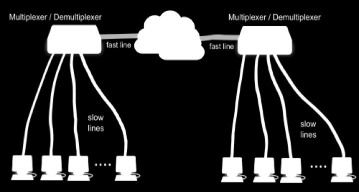
9 Multiplexer uses Muxes are very useful whenever you need to select from multiple input values. ú Example: ú Surveillance video monitors, ú Digital cable boxes, ú routers. 9


10 Adder circuits 10
11 Adders Also known as binary adders. ú Small circuit devices that add two 1-bit number. ú Combined together to create iterative combinational circuits add multiple-bit numbers Types of adders: ú Half adders (HA) ú Full adders (FA) ú Ripple Carry Adder ú Carry-Look-Ahead Adder (CLA) 11
12 Review of Binary Math 12
13 Review of Binary Math Each digit of a decimal number represents a power of 10: 258 = 2x x x10 0 Each digit of a binary number represents a power of 2: = 0x x x x x2 0 =
14 Unsigned binary addition = = Carry bit carry bit
15 Half Adder Input: two 1-bit numbers Output: 1-bit sum and 1-bit carry 15
16 Half Adders A 2-input, 1-bit width binary adder that performs the following computations: X Y CS C = X?Y S = X?Y A half adder adds two bits to produce a two-bit sum. The sum is expressed as a sum bit S and a carry bit C. C X Y HA S 16
17 Half Adder Implementation Equations and circuits for half adder units are easy to define (even without Karnaugh maps) C = X Y S = X Y + X Y = X xor Y X Y Y C HA X S S C 17
18 A half adder outputs a carry-bit, but does not take a carry-bit as input. 18
19 Full Adder takes a carry bit as input X Y X Y C HA C FA Z S S 19
20 Full Adders X Y Similar to half-adders, but with another input Z, which represents a carry-in bit. ú C and Z are sometimes labeled as C out and C in. When Z is 0, the unit behaves exactly like ú a half adder. When Z is 1: X Y Z CS C FA S Z 20
21 Full Adder Design X Y Z C S C Y Z Y Z Y Z Y Z X X S Y Z Y Z Y Z Y Z X X C = X Y + X Z + Y Z C = X Y + (X xor Y) Z S = X xor Y xor Z For gate reuse(x xor Y) considering both C and S 21
22 Full Adder Design S = X xor Y xor Z The C term can also be rewritten as: C = X Y + (X xor Y) Z G X Y Two terms come from this: ú X Y = carry generate (G). P Z Whether X and Y generate a carry bit ú X xor Y = carry propagate (P). Whether carry will be propagated to Cout Results in this circuit à C out S 22
 short int, unsigned short int: 16 bits long long int, unsigned long long int: 64 bit char,")
23 Now we can add one bit properly, but most of the numbers we use have more than one bits. int, unsigned int: 32 bits (architecture-dependent) short int, unsigned short int: 16 bits long long int, unsigned long long int: 64 bit char, unsigned char: 8 bits How do we add multiple-bit numbers? 23
24 X Y C HA S X Y C FA Z S 24
25 Each full adder takes in a carry bit and outputs a carry bit. Each full adder can take in a carry bit which is output by another full adder. That is, they can be chained up. 25
26 Ripple-Carry Binary Adder Full adders chained up, for multiple-bit addition 26
27 Ripple-Carry Binary Adder Full adder units are chained together in order to perform operations on signal vectors. X Y 4 4 X 3 Y 3 X 2 Y 2 X 1 Y 1 X 0 Y 0 C out Adder C in C out FA C 3 FA C 2 FA C 1 FA C in 4 S S 3 S 2 S 1 S 0 S 3 S 2 S 1 S 0 is the sum of X 3 X 2 X 1 X 0 and Y 3 Y 2 Y 1 Y 0 27
28 The role of C in Why can t we just have a half-adder for the smallest (rightmost) bit? Because if we can use it to do subtraction! X 3 Y 3 X 2 Y 2 X 1 Y 1 X 0 Y 0 C out FA C 3 FA C 2 FA C 1 FA C in S 3 S 2 S 1 S 0 28

29 Let s play a game 1. Pick two numbers between 0 and Convert both numbers to 5-bit binary form 3. Invert each digit of the smaller number 4. Add up the big binary number and the inverted small binary number 5. Add 1 to the result, keep the lowest 5 digits 6. Convert the result to a decimal number What do you get? You just did subtraction without doing subtraction! 29
30 Subtractors Subtractors are an extension of adders. ú Basically, perform addition on a negative number. Before we can do subtraction, need to understand negative binary numbers. Two types: ú Unsigned = a separate bit exists for the sign; data bits store the positive version of the number. ú Signed = all bits are used to store a 2 s complement negative number. 30
31 Two s complement Need to know how to get 1 s complement: ú Given number X with n bits, take (2 n -1)-X ú Negates each individual bit (bitwise NOT) à à s complement = (1 s complement + 1) à à Know this! Note: Adding a 2 s complement number to the original number produces a result of zero. 31
32 (2 s complement of A) + A = 0. The 2 s complement of A is like -A 32
33 Unsigned subtraction (separate sign bit) General algorithm for A - B: 1. Get the 2 s complement of B (-B) 2. Add that value to A 3. If there is an end carry (C out is high), the final result is positive and does not change. 4. If there is no end carry (C out is low), get the 2 s complement of the result (B-A) and add a negative sign to it, or set the sign bit high (-(B-A) = A-B). 33
34 Unsigned subtraction example carry bit no carry bit s complement sign bit is low (positive) sign bit is high (negative)
35 Signed subtraction (easier) Store negative numbers in 2 s complement notation. ú Subtraction can then be performed by using the binary adder circuit with negative numbers. ú To compute A B, just do A + (-B) ú Need to get -B first (the 2 s complement of B) 35
36 Signed subtraction example (6-bit) is is is (2 s complement of 32) is which is -2 36
37 Signed addition example (6-bit) is is : This is -20! The supposed result 44 is exceeding the range of 6-bit signed integers. This is called an overflow. 37
38 Now you understand C code better #include <stdio.h> int main() { } /* char is 8-bit integer */ signed char a = 100; signed char b = 120; signed char s = a + b; printf("%d\n", s); 38
39 Trivia about sign numbers The largest positive 8-bit signed integer? = 127 (0 followed by all 1) The smallest negative 8-bit signed integer? = -128 (1 followed by all 0) The binary form 8-bit signed integer -1? (all one) For n-bit signed number there are 2 n possible values 2 n-1 are negative numbers (e.g. 8 bit, -1 to -128) 2 n-1-1 are positive number (e.g. 8 bit, 1 to 127) and a zero 39

40 -128: (signed) 40

41 Subtraction circuit Y 3 Y 2 Y 1 Y 0 Sub X 3 X 2 X 1 X 0 Invert all the digits (if sub = 1) C out FA S 3 C 3 FA S 2 C 2 FA S 1 C 1 FA S 0 C in Add 1, so getting 2 s complement If sub = 0, S = X + Y If sub = 1, S = X Y One circuit, both adder or subtractor 41

42 Decoders 42

43 What is a decoder? 5-bit input, encoded original information Decoder number 1 number 2 number 3 number 10 rock! good job!.. The original information 43
44 Decoders Decoders are essentially translators. ú Translate from the output of one circuit to the input of another. Example: Binary signal splitter ú Activates one of four output lines, based on a twodigit binary number. X 1 X 0 Decoder A B C D 44
45 Demultiplexers Related to decoders: demultiplexers. ú Does multiplexer operation, in reverse. S S 1 S 0 M n 0 1 n n X Y M n n n n n W X Y Z 45
46 Multiplexer: Choose one from multiple inputs as output Demultiplexer: One input chooses from multiple outputs 46


47 7-segment decoder Common and useful decoder application. ú Translate from a 4-digit binary number to the seven segments of a digital display. ú Each output segment has a particular 5 logic that defines it. ú Example: Segment 0 4 Activate for values: 0, 2, 3, 5, 6, 7, 8, 9. In binary: 0000, 0010, 0011, 0101, 0110, 0111, 1000, ú First step: Build the truth table and K-map
48 Note What we talk about here is NOT the same as what we do in Lab 2 In labs we translate numbers 0, 1, 3, 4, 5, 6 to displayed letters such as (H, E, L, L, O, _, E, L, I) ú This is specially defined for the lab Here we are talking about translating 0, 1, 2, 3, 4,, to displayed 0, 1, 2, 3, 4,... ú This is more common use 48
49 7-segment decoder 0 For 7-seg decoders, turning a segment on involves driving it low. (active low) ú (In Lab 2, we treat it like active high. It s OK because Logisim does autoconversion to make it work) ú i.e. Assuming a 4-digit binary number, segment 0 is low whenever input number is 0000, 0010, 0011, 0101, 0110, 0111, 1000 or 1001, and high whenever input number is 0001 or ú This create a truth table and map like the following 49
50 7-segment decoder X 3 X 2 X 1 X 0 HEX X 1 X 0 X 1 X 0 X 1 X 0 X 1 X 0 X 3 X X 3 X X 3 X 2 X X X X X 3 X X X HEX0 = X 3 X 2 X 1 X 0 + X 3 X 2 X 1 X 0 But what about input values from 1010 to 1111? 6 rows missing! ~
51 Don t care values Some input values will never happen, so their output values do not have to be defined. ú Recorded as X in the Karnaugh map. These values can be assigned to whatever values you want, when constructing the final circuit. X 1 X 0 X 1 X 0 X 1 X 0 X 1 X 0 X 3 X X 3 X X 3 X 2 X X X X X 3 X X X HEX0 = X 3 X 2 X 1 X 0 + X 2 X 1 X 0 Boxes can cover x s, or not, whichever you like. 51
52 0 Again for segment X 3 X 2 X 1 X 0 HEX X 1 X 0 X 1 X 0 X 1 X 0 X 1 X 0 X 3 X X 3 X X 3 X 2 X X X X X 3 X X X HEX1 = X 2 X 1 X 0 + X 2 X 1 X
53 0 Again for segment X 3 X 2 X 1 X 0 HEX X 1 X 0 X 1 X 0 X 1 X 0 X 1 X 0 X 3 X X 3 X X 3 X 2 X X X X X 3 X X X HEX2 = X 2 X 1 X
54 The final 7-seg decoder Decoders all look the same, except for the inputs and outputs. Unlike other devices, the implementation differs from decoder to decoder. X 3 X 2 X 1 X 0 7-seg decoder HEX6 HEX5 HEX4 HEX3 HEX2 HEX1 HEX0 54

55 Comparators (leftover from last week) 55


56 Comparators A circuit that takes in two input vectors, and determines if the first is greater than, less than or equal to the second. How does one make that in a circuit? 56
57 Basic Comparators A B Consider two binary numbers A and B, where A and B are one bit long. The circuits for this would be: ú A==B: ú A>B: ú A<B: A B + A B A B A B Comparator A B A=B A>B A<B 57
58 Basic Comparators What if A and B are two bits long? The terms for this circuit for have to expand to reflect the second signal. For example: A 1 A 0 B 1 B 0 Comparator A=B A>B A<B ú A==B: (A 1 B 1 +A 1 B 1 ) (A 0 B 0 +A 0 B 0 ) Make sure that the values of bit 1 are the same Make sure that the values of bit 0 are the same 58
59 Basic Comparators A 1 A 0 B 1 B 0 What about checking if A is greater or less than B? ú A>B: Comparator A 1 B 1 + (A 1 B 1 +A 1 B 1 ) (A 0 B 0 ) A=B A>B A<B Check if first bit satisfies condition If not, check that the first bits are equal and then do the 1-bit comparison ú A<B: A 1 B 1 + (A 1 B 1 +A 1 B 1 ) (A 0 B 0 ) A > B if and only if A1 > B1 or (A1 = B1 and A0 > B0) 59
60 Comparing large numbers The circuit complexity of comparators increases quickly as the input size increases. For comparing large number, it may make more sense to just use a subtractor. ú Subtract and then check the sign bit. 60
61 Today we learned How a computer does following things Control the flow of signal (mux and demux) Arithmetic operations: adder, subtractor Decoder comparators Next week: Sequential circuits: circuits that have memories. 61
Systems I: Computer Organization and Architecture
 Systems I: Computer Organization and Architecture Lecture 6 - Combinational Logic Introduction A combinational circuit consists of input variables, logic gates, and output variables. The logic gates accept
Design of Sequential Circuits
 Design of Sequential Circuits Seven Steps: Construct a state diagram (showing contents of flip flop and inputs with next state) Assign letter variables to each flip flop and each input and output variable
Combinational Logic. By : Ali Mustafa
 Combinational Logic By : Ali Mustafa Contents Adder Subtractor Multiplier Comparator Decoder Encoder Multiplexer How to Analyze any combinational circuit like this? Analysis Procedure To obtain the output
Combinational Logic. Mantıksal Tasarım BBM231. section instructor: Ufuk Çelikcan
 Combinational Logic Mantıksal Tasarım BBM23 section instructor: Ufuk Çelikcan Classification. Combinational no memory outputs depends on only the present inputs expressed by Boolean functions 2. Sequential
Fundamentals of Digital Design
 Fundamentals of Digital Design Digital Radiation Measurement and Spectroscopy NE/RHP 537 1 Binary Number System The binary numeral system, or base-2 number system, is a numeral system that represents numeric
Logic. Combinational. inputs. outputs. the result. system can
 Digital Electronics Combinational Logic Functions Digital logic circuits can be classified as either combinational or sequential circuits. A combinational circuit is one where the output at any time depends
Numbers and Arithmetic
 Numbers and Arithmetic See: P&H Chapter 2.4 2.6, 3.2, C.5 C.6 Hakim Weatherspoon CS 3410, Spring 2013 Computer Science Cornell University Big Picture: Building a Processor memory inst register file alu
Numbers and Arithmetic
 Numbers and Arithmetic See: P&H Chapter 2.4 2.6, 3.2, C.5 C.6 Hakim Weatherspoon CS 3410, Spring 2013 Computer Science Cornell University Big Picture: Building a Processor memory inst register file alu
Numbers & Arithmetic. Hakim Weatherspoon CS 3410, Spring 2012 Computer Science Cornell University. See: P&H Chapter , 3.2, C.5 C.
 Numbers & Arithmetic Hakim Weatherspoon CS 3410, Spring 2012 Computer Science Cornell University See: P&H Chapter 2.4-2.6, 3.2, C.5 C.6 Example: Big Picture Computer System Organization and Programming
ECE 2300 Digital Logic & Computer Organization
 ECE 23 Digital Logic & Computer Organization Spring 28 Combinational Building Blocks Lecture 5: Announcements Lab 2 prelab due tomorrow HW due Friday HW 2 to be posted on Thursday Lecture 4 to be replayed
Hakim Weatherspoon CS 3410 Computer Science Cornell University
 Hakim Weatherspoon CS 3410 Computer Science Cornell University The slides are the product of many rounds of teaching CS 3410 by Professors Weatherspoon, Bala, Bracy, and Sirer. memory inst 32 register
211: Computer Architecture Summer 2016
 211: Computer Architecture Summer 2016 Liu Liu Topic: Storage Project3 Digital Logic - Storage: Recap - Review: cache hit rate - Project3 - Digital Logic: - truth table => SOP - simplification: Boolean
COMBINATIONAL LOGIC FUNCTIONS
 COMBINATIONAL LOGIC FUNCTIONS Digital logic circuits can be classified as either combinational or sequential circuits. A combinational circuit is one where the output at any time depends only on the present
CprE 281: Digital Logic
 CprE 281: Digital Logic Instructor: Alexander Stoytchev http://www.ece.iastate.edu/~alexs/classes/ Signed Numbers CprE 281: Digital Logic Iowa State University, Ames, IA Copyright Alexander Stoytchev Administrative
Adders, subtractors comparators, multipliers and other ALU elements
 CSE4: Components and Design Techniques for Digital Systems Adders, subtractors comparators, multipliers and other ALU elements Instructor: Mohsen Imani UC San Diego Slides from: Prof.Tajana Simunic Rosing
Module 2. Basic Digital Building Blocks. Binary Arithmetic & Arithmetic Circuits Comparators, Decoders, Encoders, Multiplexors Flip-Flops
 Module 2 asic Digital uilding locks Lecturer: Dr. Yongsheng Gao Office: Tech 3.25 Email: Web: Structure: Textbook: yongsheng.gao@griffith.edu.au maxwell.me.gu.edu.au 6 lecturers 1 tutorial 1 laboratory
Chapter 4. Combinational: Circuits with logic gates whose outputs depend on the present combination of the inputs. elements. Dr.
 Chapter 4 Dr. Panos Nasiopoulos Combinational: Circuits with logic gates whose outputs depend on the present combination of the inputs. Sequential: In addition, they include storage elements Combinational
Digital Logic. CS211 Computer Architecture. l Topics. l Transistors (Design & Types) l Logic Gates. l Combinational Circuits.
 l Logic Gates. l Combinational Circuits.") CS211 Computer Architecture Digital Logic l Topics l Transistors (Design & Types) l Logic Gates l Combinational Circuits l K-Maps Figures & Tables borrowed from:! http://www.allaboutcircuits.com/vol_4/index.html!
CS211 Computer Architecture Digital Logic l Topics l Transistors (Design & Types) l Logic Gates l Combinational Circuits l K-Maps Figures & Tables borrowed from:! http://www.allaboutcircuits.com/vol_4/index.html!
ECE 545 Digital System Design with VHDL Lecture 1. Digital Logic Refresher Part A Combinational Logic Building Blocks
 ECE 545 Digital System Design with VHDL Lecture Digital Logic Refresher Part A Combinational Logic Building Blocks Lecture Roadmap Combinational Logic Basic Logic Review Basic Gates De Morgan s Law Combinational
Computer Science 324 Computer Architecture Mount Holyoke College Fall Topic Notes: Digital Logic
 Computer Science 324 Computer Architecture Mount Holyoke College Fall 2007 Topic Notes: Digital Logic Our goal for the next few weeks is to paint a a reasonably complete picture of how we can go from transistor
Digital System Design Combinational Logic. Assoc. Prof. Pradondet Nilagupta
 Digital System Design Combinational Logic Assoc. Prof. Pradondet Nilagupta pom@ku.ac.th Acknowledgement This lecture note is modified from Engin112: Digital Design by Prof. Maciej Ciesielski, Prof. Tilman
CS61C : Machine Structures
 CS 61C L15 Blocks (1) inst.eecs.berkeley.edu/~cs61c/su05 CS61C : Machine Structures Lecture #15: Combinational Logic Blocks Outline CL Blocks Latches & Flip Flops A Closer Look 2005-07-14 Andy Carle CS
Carry Look Ahead Adders
 Carry Look Ahead Adders Lesson Objectives: The objectives of this lesson are to learn about: 1. Carry Look Ahead Adder circuit. 2. Binary Parallel Adder/Subtractor circuit. 3. BCD adder circuit. 4. Binary
Adders, subtractors comparators, multipliers and other ALU elements
 CSE4: Components and Design Techniques for Digital Systems Adders, subtractors comparators, multipliers and other ALU elements Adders 2 Circuit Delay Transistors have instrinsic resistance and capacitance
CPE100: Digital Logic Design I
 Professor Brendan Morris, SEB 3216, brendan.morris@unlv.edu CPE100: Digital Logic Design I Final Review http://www.ee.unlv.edu/~b1morris/cpe100/ 2 Logistics Tuesday Dec 12 th 13:00-15:00 (1-3pm) 2 hour
CS61C : Machine Structures
 inst.eecs.berkeley.edu/~cs61c/su05 CS61C : Machine Structures Lecture #15: Combinational Logic Blocks 2005-07-14 CS 61C L15 Blocks (1) Andy Carle Outline CL Blocks Latches & Flip Flops A Closer Look CS
ECE/CS 250 Computer Architecture
 ECE/CS 250 Computer Architecture Basics of Logic Design: Boolean Algebra, Logic Gates (Combinational Logic) Tyler Bletsch Duke University Slides are derived from work by Daniel J. Sorin (Duke), Alvy Lebeck
IT T35 Digital system desigm y - ii /s - iii
 UNIT - II Combinational Logic Adders subtractors code converters binary parallel adder decimal adder magnitude comparator encoders decoders multiplexers demultiplexers-binarymultiplier Parity generator
CHAPTER1: Digital Logic Circuits Combination Circuits
 CS224: Computer Organization S.KHABET CHAPTER1: Digital Logic Circuits Combination Circuits 1 PRIMITIVE LOGIC GATES Each of our basic operations can be implemented in hardware using a primitive logic gate.
CMP 334: Seventh Class
 CMP 334: Seventh Class Performance HW 5 solution Averages and weighted averages (review) Amdahl's law Ripple-carry adder circuits Binary addition Half-adder circuits Full-adder circuits Subtraction, negative
Hardware Design I Chap. 4 Representative combinational logic
 Hardware Design I Chap. 4 Representative combinational logic E-mail: shimada@is.naist.jp Already optimized circuits There are many optimized circuits which are well used You can reduce your design workload
EE 209 Logic Cumulative Exam Name:
 EE 209 Logic Cumulative Exam Name: 1.) Answer the following questions as True or False a.) A 4-to-1 multiplexer requires at least 4 select lines: true / false b.) An 8-to-1 mux and no other logi can be
Logic and Computer Design Fundamentals. Chapter 5 Arithmetic Functions and Circuits
 Logic and Computer Design Fundamentals Chapter 5 Arithmetic Functions and Circuits Arithmetic functions Operate on binary vectors Use the same subfunction in each bit position Can design functional block
Combinational Logic. Lan-Da Van ( 范倫達 ), Ph. D. Department of Computer Science National Chiao Tung University Taiwan, R.O.C.
, Ph. D. Department of Computer Science National Chiao Tung University Taiwan, R.O.C.") Combinational Logic ( 范倫達 ), Ph. D. Department of Computer Science National Chiao Tung University Taiwan, R.O.C. Fall, 2010 ldvan@cs.nctu.edu.tw http://www.cs.nctu.edu.tw/~ldvan/ Combinational Circuits
Combinational Logic ( 范倫達 ), Ph. D. Department of Computer Science National Chiao Tung University Taiwan, R.O.C. Fall, 2010 ldvan@cs.nctu.edu.tw http://www.cs.nctu.edu.tw/~ldvan/ Combinational Circuits
Binary addition example worked out
 Binary addition example worked out Some terms are given here Exercise: what are these numbers equivalent to in decimal? The initial carry in is implicitly 0 1 1 1 0 (Carries) 1 0 1 1 (Augend) + 1 1 1 0
Section 3: Combinational Logic Design. Department of Electrical Engineering, University of Waterloo. Combinational Logic
 Section 3: Combinational Logic Design Major Topics Design Procedure Multilevel circuits Design with XOR gates Adders and Subtractors Binary parallel adder Decoders Encoders Multiplexers Programmed Logic
Class Website:
 ECE 20B, Winter 2003 Introduction to Electrical Engineering, II LECTURE NOTES #5 Instructor: Andrew B. Kahng (lecture) Email: abk@ece.ucsd.edu Telephone: 858-822-4884 office, 858-353-0550 cell Office:
Binary addition (1-bit) P Q Y = P + Q Comments Carry = Carry = Carry = Carry = 1 P Q
 P Q Y = P + Q Comments Carry = Carry = Carry = Carry = 1 P Q") Digital Arithmetic In Chapter 2, we have discussed number systems such as binary, hexadecimal, decimal, and octal. We have also discussed sign representation techniques, for example, sign-bit representation
Digital Arithmetic In Chapter 2, we have discussed number systems such as binary, hexadecimal, decimal, and octal. We have also discussed sign representation techniques, for example, sign-bit representation
Number System. Decimal to binary Binary to Decimal Binary to octal Binary to hexadecimal Hexadecimal to binary Octal to binary
 Number System Decimal to binary Binary to Decimal Binary to octal Binary to hexadecimal Hexadecimal to binary Octal to binary BOOLEAN ALGEBRA BOOLEAN LOGIC OPERATIONS Logical AND Logical OR Logical COMPLEMENTATION
Combinational Logic. Lan-Da Van ( 范倫達 ), Ph. D. Department of Computer Science National Chiao Tung University Taiwan, R.O.C.
, Ph. D. Department of Computer Science National Chiao Tung University Taiwan, R.O.C.") Combinational Logic ( 范倫達 ), Ph. D. Department of Computer Science National Chiao Tung University Taiwan, R.O.C. Fall, 2017 ldvan@cs.nctu.edu.tw http://www.cs.nctu.edu.tw/~ldvan/ Combinational Circuits
Combinational Logic ( 范倫達 ), Ph. D. Department of Computer Science National Chiao Tung University Taiwan, R.O.C. Fall, 2017 ldvan@cs.nctu.edu.tw http://www.cs.nctu.edu.tw/~ldvan/ Combinational Circuits
E40M. Binary Numbers. M. Horowitz, J. Plummer, R. Howe 1
 E40M Binary Numbers M. Horowitz, J. Plummer, R. Howe 1 Reading Chapter 5 in the reader A&L 5.6 M. Horowitz, J. Plummer, R. Howe 2 Useless Box Lab Project #2 Adding a computer to the Useless Box alows us
Lecture 2 Review on Digital Logic (Part 1)
") Lecture 2 Review on Digital Logic (Part 1) Xuan Silvia Zhang Washington University in St. Louis http://classes.engineering.wustl.edu/ese461/ Grading Engagement 5% Review Quiz 10% Homework 10% Labs 40%
Lecture 2 Review on Digital Logic (Part 1) Xuan Silvia Zhang Washington University in St. Louis http://classes.engineering.wustl.edu/ese461/ Grading Engagement 5% Review Quiz 10% Homework 10% Labs 40%
Menu. 7-Segment LED. Misc. 7-Segment LED MSI Components >MUX >Adders Memory Devices >D-FF, RAM, ROM Computer/Microprocessor >GCPU
 Menu 7-Segment LED MSI Components >MUX >Adders Memory Devices >D-FF, RAM, ROM Computer/Microprocessor >GCPU Look into my... 1 7-Segment LED a b c h GND c g b d f a e h Show 7-segment LED in LogicWorks,
CprE 281: Digital Logic
 CprE 281: Digital Logic Instructor: Alexander Stoytchev http://www.ece.iastate.edu/~alexs/classes/ Fast Adders CprE 281: Digital Logic Iowa State University, Ames, IA Copyright Alexander Stoytchev HW5
Combina-onal Logic Chapter 4. Topics. Combina-on Circuit 10/13/10. EECE 256 Dr. Sidney Fels Steven Oldridge
 Combina-onal Logic Chapter 4 EECE 256 Dr. Sidney Fels Steven Oldridge Topics Combina-onal circuits Combina-onal analysis Design procedure simple combined to make complex adders, subtractors, converters
ELEN Electronique numérique
 ELEN0040 - Electronique numérique Patricia ROUSSEAUX Année académique 2014-2015 CHAPITRE 3 Combinational Logic Circuits ELEN0040 3-4 1 Combinational Functional Blocks 1.1 Rudimentary Functions 1.2 Functions
Function of Combinational Logic ENT263
 Function of Combinational Logic ENT263 Chapter Objectives Distinguish between half-adder and full-adder Use BCD-to-7-segment decoders in display systems Apply multiplexer in data selection Use decoders
Looking at a two binary digit sum shows what we need to extend addition to multiple binary digits.
 A Full Adder The half-adder is extremely useful until you want to add more that one binary digit quantities. The slow way to develop a two binary digit adders would be to make a truth table and reduce
CSE 20 DISCRETE MATH. Fall
 CSE 20 DISCRETE MATH Fall 2017 http://cseweb.ucsd.edu/classes/fa17/cse20-ab/ Today's learning goals Describe and use algorithms for integer operations based on their expansions Relate algorithms for integer
Midterm Exam Two is scheduled on April 8 in class. On March 27 I will help you prepare Midterm Exam Two.
 Announcements Midterm Exam Two is scheduled on April 8 in class. On March 27 I will help you prepare Midterm Exam Two. Chapter 5 1 Chapter 3: Part 3 Arithmetic Functions Iterative combinational circuits
ECE 250 / CPS 250 Computer Architecture. Basics of Logic Design Boolean Algebra, Logic Gates
 ECE 250 / CPS 250 Computer Architecture Basics of Logic Design Boolean Algebra, Logic Gates Benjamin Lee Slides based on those from Andrew Hilton (Duke), Alvy Lebeck (Duke) Benjamin Lee (Duke), and Amir
UNIT II COMBINATIONAL CIRCUITS:
 UNIT II COMBINATIONAL CIRCUITS: INTRODUCTION: The digital system consists of two types of circuits, namely (i) (ii) Combinational circuits Sequential circuits Combinational circuit consists of logic gates
MODULAR CIRCUITS CHAPTER 7
 CHAPTER 7 MODULAR CIRCUITS A modular circuit is a digital circuit that performs a specific function or has certain usage. The modular circuits to be introduced in this chapter are decoders, encoders, multiplexers,
Chapter 5 Arithmetic Circuits
 Chapter 5 Arithmetic Circuits SKEE2263 Digital Systems Mun im/ismahani/izam {munim@utm.my,e-izam@utm.my,ismahani@fke.utm.my} February 11, 2016 Table of Contents 1 Iterative Designs 2 Adders 3 High-Speed
CSE140: Components and Design Techniques for Digital Systems. Decoders, adders, comparators, multipliers and other ALU elements. Tajana Simunic Rosing
 CSE4: Components and Design Techniques for Digital Systems Decoders, adders, comparators, multipliers and other ALU elements Tajana Simunic Rosing Mux, Demux Encoder, Decoder 2 Transmission Gate: Mux/Tristate
Combinational Logic Design Arithmetic Functions and Circuits
 Combinational Logic Design Arithmetic Functions and Circuits Overview Binary Addition Half Adder Full Adder Ripple Carry Adder Carry Look-ahead Adder Binary Subtraction Binary Subtractor Binary Adder-Subtractor
Logic and Boolean algebra
 Computer Mathematics Week 7 Logic and Boolean algebra College of Information Science and Engineering Ritsumeikan University last week coding theory channel coding information theory concept Hamming distance
UNSIGNED BINARY NUMBERS DIGITAL ELECTRONICS SYSTEM DESIGN WHAT ABOUT NEGATIVE NUMBERS? BINARY ADDITION 11/9/2018
 DIGITAL ELECTRONICS SYSTEM DESIGN LL 2018 PROFS. IRIS BAHAR & ROD BERESFORD NOVEMBER 9, 2018 LECTURE 19: BINARY ADDITION, UNSIGNED BINARY NUMBERS For the binary number b n-1 b n-2 b 1 b 0. b -1 b -2 b
Digital Logic: Boolean Algebra and Gates. Textbook Chapter 3
 Digital Logic: Boolean Algebra and Gates Textbook Chapter 3 Basic Logic Gates XOR CMPE12 Summer 2009 02-2 Truth Table The most basic representation of a logic function Lists the output for all possible
UNIT III Design of Combinational Logic Circuits. Department of Computer Science SRM UNIVERSITY
 UNIT III Design of ombinational Logic ircuits Department of omputer Science SRM UNIVERSITY Introduction to ombinational ircuits Logic circuits for digital systems may be ombinational Sequential combinational
SIR C.R.REDDY COLLEGE OF ENGINEERING ELURU DIGITAL INTEGRATED CIRCUITS (DIC) LABORATORY MANUAL III / IV B.E. (ECE) : I - SEMESTER
 LABORATORY MANUAL III / IV B.E. (ECE) : I - SEMESTER") SIR C.R.REDDY COLLEGE OF ENGINEERING ELURU 534 007 DIGITAL INTEGRATED CIRCUITS (DIC) LABORATORY MANUAL III / IV B.E. (ECE) : I - SEMESTER DEPARTMENT OF ELECTRONICS AND COMMUNICATION ENGINEERING DIGITAL
SIR C.R.REDDY COLLEGE OF ENGINEERING ELURU 534 007 DIGITAL INTEGRATED CIRCUITS (DIC) LABORATORY MANUAL III / IV B.E. (ECE) : I - SEMESTER DEPARTMENT OF ELECTRONICS AND COMMUNICATION ENGINEERING DIGITAL
Propositional Logic. Logical Expressions. Logic Minimization. CNF and DNF. Algebraic Laws for Logical Expressions CSC 173
 Propositional Logic CSC 17 Propositional logic mathematical model (or algebra) for reasoning about the truth of logical expressions (propositions) Logical expressions propositional variables or logical
Lecture 10: Synchronous Sequential Circuits Design
 Lecture 0: Synchronous Sequential Circuits Design. General Form Input Combinational Flip-flops Combinational Output Circuit Circuit Clock.. Moore type has outputs dependent only on the state, e.g. ripple
Chapter 03: Computer Arithmetic. Lesson 03: Arithmetic Operations Adder and Subtractor circuits Design
 Chapter 03: Computer Arithmetic Lesson 03: Arithmetic Operations Adder and Subtractor circuits Design Objective To understand adder circuit Subtractor circuit Fast adder circuit 2 Adder Circuit 3 Full
Building a Computer Adder
 Logic Gates are used to translate Boolean logic into circuits. In the abstract it is clear that we can build AND gates that perform the AND function and OR gates that perform the OR function and so on.
3. Combinational Circuit Design
 CSEE 3827: Fundamentals of Computer Systems, Spring 2 3. Combinational Circuit Design Prof. Martha Kim (martha@cs.columbia.edu) Web: http://www.cs.columbia.edu/~martha/courses/3827/sp/ Outline (H&H 2.8,
CprE 281: Digital Logic
 CprE 28: Digital Logic Instructor: Alexander Stoytchev http://www.ece.iastate.edu/~alexs/classes/ Simple Processor CprE 28: Digital Logic Iowa State University, Ames, IA Copyright Alexander Stoytchev Digital
Combinational Logic. Course Instructor Mohammed Abdul kader
 Combinational Logic Contents: Combinational and Sequential digital circuits. Design Procedure of combinational circuit. Adders: Half adder and Full adder. Subtractors: Half Subtractor and Full Subtractor.
Boolean Algebra and Digital Logic 2009, University of Colombo School of Computing
 IT 204 Section 3.0 Boolean Algebra and Digital Logic Boolean Algebra 2 Logic Equations to Truth Tables X = A. B + A. B + AB A B X 0 0 0 0 3 Sum of Products The OR operation performed on the products of
CS1800: Hex & Logic. Professor Kevin Gold
 CS1800: Hex & Logic Professor Kevin Gold Reviewing Last Time: Binary Last time, we saw that arbitrary numbers can be represented in binary. Each place in a binary number stands for a different power of
COE 202: Digital Logic Design Combinational Circuits Part 2. Dr. Ahmad Almulhem ahmadsm AT kfupm Phone: Office:
 COE 202: Digital Logic Design Combinational Circuits Part 2 Dr. Ahmad Almulhem Email: ahmadsm AT kfupm Phone: 860-7554 Office: 22-324 Objectives Arithmetic Circuits Adder Subtractor Carry Look Ahead Adder
Chapter 5. Digital systems. 5.1 Boolean algebra Negation, conjunction and disjunction
 Chapter 5 igital systems digital system is any machine that processes information encoded in the form of digits. Modern digital systems use binary digits, encoded as voltage levels. Two voltage levels,
DIGITAL TECHNICS. Dr. Bálint Pődör. Óbuda University, Microelectronics and Technology Institute
 DIGITAL TECHNICS Dr. Bálint Pődör Óbuda University, Microelectronics and Technology Institute 4. LECTURE: COMBINATIONAL LOGIC DESIGN: ARITHMETICS (THROUGH EXAMPLES) 2016/2017 COMBINATIONAL LOGIC DESIGN:
A crash course in Digital Logic
 crash course in Digital Logic Computer rchitecture 1DT016 distance Fall 2017 http://xyx.se/1dt016/index.php Per Foyer Mail: per.foyer@it.uu.se Per.Foyer@it.uu.se 2017 1 We start from here Gates Flip-flops
Combinational Logic. Jee-Hwan Ryu. School of Mechanical Engineering Korea University of Technology and Education
 MEC5 디지털공학 Combinational Logic Jee-Hwan Ryu School of Mechanical Engineering Combinational circuits Outputs are determined from the present inputs Consist of input/output variables and logic gates inary
Appendix B. Review of Digital Logic. Baback Izadi Division of Engineering Programs
 Appendix B Review of Digital Logic Baback Izadi Division of Engineering Programs bai@engr.newpaltz.edu Elect. & Comp. Eng. 2 DeMorgan Symbols NAND (A.B) = A +B NOR (A+B) = A.B AND A.B = A.B = (A +B ) OR
Understand Video Games; Understand Everything
 Understand Video Games; Understand Everything Stephen A. Edwards Columbia University The Subject of this Lecture 0 The Subjects of this Lecture 0 1 But let your communication be, Yea, yea; Nay, nay: for
Sample Test Paper - I
 Scheme G Sample Test Paper - I Course Name : Computer Engineering Group Marks : 25 Hours: 1 Hrs. Q.1) Attempt any THREE: 09 Marks a) Define i) Propagation delay ii) Fan-in iii) Fan-out b) Convert the following:
Review for Test 1 : Ch1 5
 Review for Test 1 : Ch1 5 October 5, 2006 Typeset by FoilTEX Positional Numbers 527.46 10 = (5 10 2 )+(2 10 1 )+(7 10 0 )+(4 10 1 )+(6 10 2 ) 527.46 8 = (5 8 2 ) + (2 8 1 ) + (7 8 0 ) + (4 8 1 ) + (6 8
CSEE 3827: Fundamentals of Computer Systems. Combinational Circuits
 CSEE 3827: Fundamentals of Computer Systems Combinational Circuits Outline (M&K 3., 3.3, 3.6-3.9, 4.-4.2, 4.5, 9.4) Combinational Circuit Design Standard combinational circuits enabler decoder encoder
Digital Electronics Circuits 2017
 JSS SCIENCE AND TECHNOLOGY UNIVERSITY Digital Electronics Circuits (EC37L) Lab in-charge: Dr. Shankraiah Course outcomes: After the completion of laboratory the student will be able to, 1. Simplify, design
Overview. Multiplexor. cs281: Introduction to Computer Systems Lab02 Basic Combinational Circuits: The Mux and the Adder
 cs281: Introduction to Computer Systems Lab02 Basic Combinational Circuits: The Mux and the Adder Overview The objective of this lab is to understand two basic combinational circuits the multiplexor and
COSC 243. Introduction to Logic And Combinatorial Logic. Lecture 4 - Introduction to Logic and Combinatorial Logic. COSC 243 (Computer Architecture)
") COSC 243 Introduction to Logic And Combinatorial Logic 1 Overview This Lecture Introduction to Digital Logic Gates Boolean algebra Combinatorial Logic Source: Chapter 11 (10 th edition) Source: J.R. Gregg,
COSC 243 Introduction to Logic And Combinatorial Logic 1 Overview This Lecture Introduction to Digital Logic Gates Boolean algebra Combinatorial Logic Source: Chapter 11 (10 th edition) Source: J.R. Gregg,
Floating Point Representation and Digital Logic. Lecture 11 CS301
 Floating Point Representation and Digital Logic Lecture 11 CS301 Administrative Daily Review of today s lecture w Due tomorrow (10/4) at 8am Lab #3 due Friday (9/7) 1:29pm HW #5 assigned w Due Monday 10/8
Part 1: Digital Logic and Gates. Analog vs. Digital waveforms. The digital advantage. In real life...
 Part 1: Digital Logic and Gates Analog vs Digital waveforms An analog signal assumes a continuous range of values: v(t) ANALOG A digital signal assumes discrete (isolated, separate) values Usually there
Lecture 22 Chapters 3 Logic Circuits Part 1
 Lecture 22 Chapters 3 Logic Circuits Part 1 LC-3 Data Path Revisited How are the components Seen here implemented? 5-2 Computing Layers Problems Algorithms Language Instruction Set Architecture Microarchitecture
ECEN 248: INTRODUCTION TO DIGITAL SYSTEMS DESIGN. Week 9 Dr. Srinivas Shakkottai Dept. of Electrical and Computer Engineering
 ECEN 248: INTRODUCTION TO DIGITAL SYSTEMS DESIGN Week 9 Dr. Srinivas Shakkottai Dept. of Electrical and Computer Engineering TIMING ANALYSIS Overview Circuits do not respond instantaneously to input changes
CprE 281: Digital Logic
 CprE 28: Digital Logic Instructor: Alexander Stoytchev http://www.ece.iastate.edu/~alexs/classes/ Decoders and Encoders CprE 28: Digital Logic Iowa State University, Ames, IA Copyright Alexander Stoytchev
Logic. Basic Logic Functions. Switches in series (AND) Truth Tables. Switches in Parallel (OR) Alternative view for OR
 Truth Tables. Switches in Parallel (OR) Alternative view for OR") TOPIS: Logic Logic Expressions Logic Gates Simplifying Logic Expressions Sequential Logic (Logic with a Memory) George oole (85-864), English mathematician, oolean logic used in digital computers since
TOPIS: Logic Logic Expressions Logic Gates Simplifying Logic Expressions Sequential Logic (Logic with a Memory) George oole (85-864), English mathematician, oolean logic used in digital computers since
CMSC 313 Lecture 18 Midterm Exam returned Assign Homework 3 Circuits for Addition Digital Logic Components Programmable Logic Arrays
 CMSC 33 Lecture 8 Midterm Exam returned ssign Homework 3 Circuits for ddition Digital Logic Components Programmable Logic rrays UMC, CMSC33, Richard Chang Half dder Inputs: and Outputs:
ECE/CS 250: Computer Architecture. Basics of Logic Design: Boolean Algebra, Logic Gates. Benjamin Lee
 ECE/CS 250: Computer Architecture Basics of Logic Design: Boolean Algebra, Logic Gates Benjamin Lee Slides based on those from Alvin Lebeck, Daniel Sorin, Andrew Hilton, Amir Roth, Gershon Kedem Admin
Logic Simplification. Boolean Simplification Example. Applying Boolean Identities F = A B C + A B C + A BC + ABC. Karnaugh Maps 2/10/2009 COMP370 1
 Digital Logic COMP370 Introduction to Computer Architecture Logic Simplification It is frequently possible to simplify a logical expression. This makes it easier to understand and requires fewer gates
XI STANDARD [ COMPUTER SCIENCE ] 5 MARKS STUDY MATERIAL.
![XI STANDARD [ COMPUTER SCIENCE ] 5 MARKS STUDY MATERIAL.](/thumbs/81/84726747.jpg "XI STANDARD [ COMPUTER SCIENCE ] 5 MARKS STUDY MATERIAL.") 2017-18 XI STANDARD [ COMPUTER SCIENCE ] 5 MARKS STUDY MATERIAL HALF ADDER 1. The circuit that performs addition within the Arithmetic and Logic Unit of the CPU are called adders. 2. A unit that adds two
2017-18 XI STANDARD [ COMPUTER SCIENCE ] 5 MARKS STUDY MATERIAL HALF ADDER 1. The circuit that performs addition within the Arithmetic and Logic Unit of the CPU are called adders. 2. A unit that adds two
Combinational Logic Design Combinational Functions and Circuits
 Combinational Logic Design Combinational Functions and Circuits Overview Combinational Circuits Design Procedure Generic Example Example with don t cares: BCD-to-SevenSegment converter Binary Decoders
Z = F(X) Combinational circuit. A combinational circuit can be specified either by a truth table. Truth Table
 Combinational circuit. A combinational circuit can be specified either by a truth table. Truth Table") Lesson Objectives In this lesson, you will learn about What are combinational circuits Design procedure of combinational circuits Examples of combinational circuit design Combinational Circuits Logic circuit
Lesson Objectives In this lesson, you will learn about What are combinational circuits Design procedure of combinational circuits Examples of combinational circuit design Combinational Circuits Logic circuit
Computer Science. 19. Combinational Circuits. Computer Science COMPUTER SCIENCE. Section 6.1.
 COMPUTER SCIENCE S E D G E W I C K / W A Y N E PA R T I I : A L G O R I T H M S, M A C H I N E S, a n d T H E O R Y Computer Science Computer Science An Interdisciplinary Approach Section 6.1 ROBERT SEDGEWICK
CHAPTER VI COMBINATIONAL LOGIC BUILDING BLOCKS
 CHAPTR VI- CHAPTR VI CHAPTR VI BUILDING BLOCKS R.M. Dansereau; v.. CHAPTR VI- COMBINAT. LOGIC INTRODUCTION -INTRODUCTION Combinational logic Output at any time is determined completely by the current input.
Lecture 7: Logic design. Combinational logic circuits
 /24/28 Lecture 7: Logic design Binary digital circuits: Two voltage levels: and (ground and supply voltage) Built from transistors used as on/off switches Analog circuits not very suitable for generic
Chapter 3 Digital Logic Structures
 Chapter 3 Digital Logic Structures Original slides from Gregory Byrd, North Carolina State University Modified by C. Wilcox, M. Strout, Y. Malaiya Colorado State University Computing Layers Problems Algorithms
Latches. October 13, 2003 Latches 1
 Latches The second part of CS231 focuses on sequential circuits, where we add memory to the hardware that we ve already seen. Our schedule will be very similar to before: We first show how primitive memory