A Random Walk from Async to Sync. Paul Cunningham & Steev Wilcox
|
|
|
- Curtis Hancock
- 5 years ago
- Views:
Transcription
1 A Random Walk from Async to Sync Paul Cunningham & Steev Wilcox

2 Thank You Ivan


3 In the Beginning March 2002
4 Azuro Day 1 Some money in the bank from Angel Investors 2 employees Small Office rented from Cambridge University Computer ab Vision to automatically compile mainstream synchronous designs into low power asynchronous equivalents So why is Asynchronous design low power!?
5 Azuro Day 100 after several meetings with chip companies, VCs and lots of whiteboard time Device
6 EVE SENSITIVE AND GATE A B EDGE SENSITIVE AND GATE A B Z C Z A A B B Z A Z B B A 3X 4 transistors 12 transistors
7 Costs power to implement D delay request acknowledge Gmax < D Gmax Hard to sign-off across different process corner, voltage, temperature
8 request acknowledge acknowledge acknowledge request request
9 clock P W Gmin Hold Check: Gmin > W Setup Check: Gmax < P Gmax
10 clock Off-chip crystal oscillator P W Gmin Hold Check: Gmin > W Setup Check: Gmax < P Pulse-flopped Synchronous Design Gmax
11 clock Off-chip crystal oscillator P How do make sure the pulse width is predictable across multiple process corner, temperature and voltages? W Gmin How do you shift values in and out during chip test without violating the hold check? Hold Check: Gmin > W Setup Check: Gmax < P Gmax
12 Hold Check: Gmin > W Setup Check: Gmax < P Small W clock
13 clock D-type flip-flop (DFF) Hold Check: Gmin > W Setup Check: Gmax < P Very small and predictable W Small local circuit which can be carefully crafted and characterized across multiple process corners, voltages, temperatures

14
15 Azuro Day 1 Some money in the bank from Angel Investors 2 employees Small Office rented from Cambridge University Computer ab Vision to automatically compile mainstream synchronous designs into low power asynchronous equivalents Vision to bring the low power benefits of asynchronous design to the mainstream synchronous community
16 These delays don t all have to be the same request acknowledge acknowledge acknowledge request No data no latching (consume power only when needed) request
17 These delays don t all have to be the same request acknowledge acknowledge acknowledge request No data no latching (consume power only when needed) request
18 Power Saving Ideas Power in the clock Is wasted if the register did not capture new data Clock gating Power in the datapath Is wasted if the result of computation is not captured Guarding if ( ) b = a + If will not accept data a Don t send data + b Don t clock register
19 First Real Idea: Guard Flops Saw that flop can be decomposed T T So create Guard Flop Control accepting data Control routing of data T T T T
20 First Real Idea: Guard Flops Gained two US patents Reception was that it was still too disruptive Needed to create new standard cells New Methodologies Still too Async? Needed to come closer to the mainstream
21 Focus on Clock Gating Clock gates are like AND gates with one risingedge sensitive input Clock in Enable T Gated clock out Clock in Enable in Clock out
22 Focus on Clock Gating Clock Gating in 2002 was primitive Instantiated directly from RT expressions only if (a) b <= c; Three ways to improve: Find and exploit hierarchy Find new register-level expressions not in netlist Find sub-register-level expressions
23 Hierarchical Gating A A&B CG A&C CG CG B CG C CG Finding expressions requires BDD-based netlist traversal Rarely as simple as observing an AND gate in the netlist! Multiple levels of hierarchy usually available Heuristics to limit levels to 2 or 3 to avoid clock impact
24 Symbolic Gating Gating function CG Next-state function Use BDDs to decompose existing D-side function Gating function for whole register Next-state function assuming gating function pulled out May need to avoid decomposition If timing is tight, might need to pull out CG late in the day, and put back in old (green) function
25 Structural Gating Generalization of previously-published work: CG On it s own, this is useless Clock cap of CG as much or larger than flop! But can be combined with NAND, OR, and across subsets of registers
26 Structural Gating CG Register split into number of clusters, depending on simulation information (SAIF, VCD) Some parts of register may stay at logic 0 more than logic 1 Use OR gate for comparison CG Key is to make the whole thing activity-driven


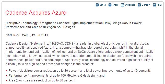
27 First Product: PowerCentric VICTORY!
28 First Product: PowerCentric NASDAQ stock price Azuro ready to launch!
29 First Product: PowerCentric NASDAQ stock price Houston, we have a problem aunch abort! Hunker down for phase
30 These delays don t all have to be the same request acknowledge acknowledge acknowledge request No data no latching (consume power only when needed) request
31 2004, In Azuro R&D Could now gate clock far more efficiently than any competitor However, we couldn t estimate effect on the clock tree Needed to generate our own clock tree synthesis algorithm Naturally, we used our Async experience
32 Azuro CTS Bottom-up clustering approach Cluster lower drivers together first More flexible, less synchronous in a way Ideally suited to deep clock gating Also ~10% lower power But has other benefits
33 Azuro CTS Productize useful skew Manage on-chip variation Azuro CTS allowed us to Tame clock complexity
34 Clock Complexity Do these flops need to be balanced? Innovated P-based scheduling algorithm to solve complex clock tree constraints
35 On-Chip Variation OCV derates hidden until CTS
36 OCV + Clock Complexity = Clock Timing Gap
37 Useful Skew Why does the clock need to arrive at every point at the same time? CK 600ps 1200ps 600ps Short stage ong stage Short stage Cycle time: 1200ps Think Async: What would we do?
38 Useful Skew CK Advance this signal 200ps Delay this signal 200ps ps 1200ps 400ps ps Short stage ong stage Short stage Cycle time now: 800ps 50% frequency improvement!
39 Useful Skew Has been tried before EDA vendors had useful skew engines Numerous academic papers on this Focus was either too lowbrow or too highbrow Tradtional approach was adding individual buffers. No ability to decrease delay. Buffers cost power. Academic approach was solving chip-wide P-style problems. Too hard for real chips (1M+ instances). No consideration of complex clocks No consideration of on-chip variation
40 Azuro CTS Manage on-chip variation Productize useful skew? Tame clock complexity


41 Traditional Design Worst Path Closure Speed limited by max D Path D1 D2 D3 Chain Clock Concurrent Design Worst Chain Closure Speed limited by avg D


42 Need to be propagated clocks slacks not ideal clocks slacks! slack1 slack2 D1 D2 slack3 slack1 = slack2 = slack3? D3

43 Clock Concurrent Optimization (CCOpt) Clock D3 Skew clocks and optimize logic concurrently Always using propagated clocks slacks
44 Azuro CTS Manage on-chip variation Productize useful skew Azuro Rubix (CCOpt) Tame clock complexity
45
46 Thank You
CSE241 VLSI Digital Circuits Winter Lecture 07: Timing II
 CSE241 VLSI Digital Circuits Winter 2003 Lecture 07: Timing II CSE241 L3 ASICs.1 Delay Calculation Cell Fall Cap\Tr 0.05 0.2 0.5 0.01 0.02 0.16 0.30 0.5 2.0 0.04 0.32 0.178 0.08 0.64 0.60 1.20 0.1ns 0.147ns
EE115C Winter 2017 Digital Electronic Circuits. Lecture 19: Timing Analysis
 EE115C Winter 2017 Digital Electronic Circuits Lecture 19: Timing Analysis Outline Timing parameters Clock nonidealities (skew and jitter) Impact of Clk skew on timing Impact of Clk jitter on timing Flip-flop-
Testability. Shaahin Hessabi. Sharif University of Technology. Adapted from the presentation prepared by book authors.
 Testability Lecture 6: Logic Simulation Shaahin Hessabi Department of Computer Engineering Sharif University of Technology Adapted from the presentation prepared by book authors Slide 1 of 27 Outline What
Problem Set 9 Solutions
 CSE 26 Digital Computers: Organization and Logical Design - 27 Jon Turner Problem Set 9 Solutions. For each of the sequential circuits shown below, draw in the missing parts of the timing diagrams. You
Timing Issues. Digital Integrated Circuits A Design Perspective. Jan M. Rabaey Anantha Chandrakasan Borivoje Nikolić. January 2003
 Digital Integrated Circuits A Design Perspective Jan M. Rabaey Anantha Chandrakasan Borivoje Nikolić Timing Issues January 2003 1 Synchronous Timing CLK In R Combinational 1 R Logic 2 C in C out Out 2
GMU, ECE 680 Physical VLSI Design 1
 ECE680: Physical VLSI Design Chapter VII Timing Issues in Digital Circuits (chapter 10 in textbook) GMU, ECE 680 Physical VLSI Design 1 Synchronous Timing (Fig. 10 1) CLK In R Combinational 1 R Logic 2
Boolean Logic Continued Prof. James L. Frankel Harvard University
 Boolean Logic Continued Prof. James L. Frankel Harvard University Version of 10:18 PM 5-Sep-2017 Copyright 2017, 2016 James L. Frankel. All rights reserved. D Latch D R S Clk D Clk R S X 0 ~S 0 = R 0 ~R
Timing Constraints in Sequential Designs. 63 Sources: TSR, Katz, Boriello & Vahid
 Timing Constraints in Sequential esigns 63 Sources: TSR, Katz, Boriello & Vahid Where we are now. What we covered last time: FSMs What we ll do next: Timing constraints Upcoming deadlines: ZyBook today:
Lecture 9: Clocking, Clock Skew, Clock Jitter, Clock Distribution and some FM
 Lecture 9: Clocking, Clock Skew, Clock Jitter, Clock Distribution and some FM Mark McDermott Electrical and Computer Engineering The University of Texas at Austin 9/27/18 VLSI-1 Class Notes Why Clocking?
Issues on Timing and Clocking
 ECE152B TC 1 Issues on Timing and Clocking X Combinational Logic Z... clock clock clock period ECE152B TC 2 Latch and Flip-Flop L CK CK 1 L1 1 L2 2 CK CK CK ECE152B TC 3 Clocking X Combinational Logic...
Synchronous Sequential Circuit
 Synchronous Sequential Circuit The change of internal state occurs in response to the synchronized clock pulses. Data are read during the clock pulse (e.g. rising-edge triggered) It is supposed to wait
Module - 19 Gated Latches
 Digital Circuits and Systems Prof. Shankar Balachandran Department of Electrical Engineering Indian Institute of Technology, Bombay And Department of Computer Science and Engineering Indian Institute of
Implementation of Clock Network Based on Clock Mesh
 International Conference on Information Technology and Management Innovation (ICITMI 2015) Implementation of Clock Network Based on Clock Mesh He Xin 1, a *, Huang Xu 2,b and Li Yujing 3,c 1 Sichuan Institute
Sequential Logic Design: Controllers
 Sequential Logic Design: Controllers Controller Design, Flip Flop Timing Copyright (c) 2012 Sean Key Standard Controller Architecture Controller A circuit that implements a FSM is referred to as a controller
The Linear-Feedback Shift Register
 EECS 141 S02 Timing Project 2: A Random Number Generator R R R S 0 S 1 S 2 1 0 0 0 1 0 1 0 1 1 1 0 1 1 1 0 1 1 0 0 1 1 0 0 The Linear-Feedback Shift Register 1 Project Goal Design a 4-bit LFSR SPEED, SPEED,
ECE 407 Computer Aided Design for Electronic Systems. Simulation. Instructor: Maria K. Michael. Overview
 407 Computer Aided Design for Electronic Systems Simulation Instructor: Maria K. Michael Overview What is simulation? Design verification Modeling Levels Modeling circuits for simulation True-value simulation
UNIVERSITY OF CALIFORNIA
 UNIVERSITY OF CALIFORNIA College of Engineering Department of Electrical Engineering and Computer Sciences Last modified on April 14, 2004 by Brian Leibowitz (bsl@eecs.berkeley.edu) Jan Rabaey Homework
Clock Strategy. VLSI System Design NCKUEE-KJLEE
 Clock Strategy Clocked Systems Latch and Flip-flops System timing Clock skew High speed latch design Phase locked loop ynamic logic Multiple phase Clock distribution Clocked Systems Most VLSI systems are
UNIVERSITY OF CALIFORNIA, BERKELEY College of Engineering Department of Electrical Engineering and Computer Sciences
 UNIVERSITY OF CALIFORNIA, BERKELEY College of Engineering Department of Electrical Engineering and Computer Sciences Elad Alon Homework #9 EECS141 PROBLEM 1: TIMING Consider the simple state machine shown
CPE/EE 422/522. Chapter 1 - Review of Logic Design Fundamentals. Dr. Rhonda Kay Gaede UAH. 1.1 Combinational Logic
 CPE/EE 422/522 Chapter - Review of Logic Design Fundamentals Dr. Rhonda Kay Gaede UAH UAH Chapter CPE/EE 422/522. Combinational Logic Combinational Logic has no control inputs. When the inputs to a combinational
Chapter 3. Digital Design and Computer Architecture, 2 nd Edition. David Money Harris and Sarah L. Harris. Chapter 3 <1>
 Chapter 3 Digital Design and Computer Architecture, 2 nd Edition David Money Harris and Sarah L. Harris Chapter 3 Chapter 3 :: Topics Introduction Latches and Flip-Flops Synchronous Logic Design Finite
Chapter 7. Sequential Circuits Registers, Counters, RAM
 Chapter 7. Sequential Circuits Registers, Counters, RAM Register - a group of binary storage elements suitable for holding binary info A group of FFs constitutes a register Commonly used as temporary storage
Timing Analysis with Clock Skew
 , Mark Horowitz 1, & Dean Liu 1 David_Harris@hmc.edu, {horowitz, dliu}@vlsi.stanford.edu March, 1999 Harvey Mudd College Claremont, CA 1 (with Stanford University, Stanford, CA) Outline Introduction Timing
Lecture 7: Logic design. Combinational logic circuits
 /24/28 Lecture 7: Logic design Binary digital circuits: Two voltage levels: and (ground and supply voltage) Built from transistors used as on/off switches Analog circuits not very suitable for generic
Xarxes de distribució del senyal de. interferència electromagnètica, consum, soroll de conmutació.
 Xarxes de distribució del senyal de rellotge. Clock skew, jitter, interferència electromagnètica, consum, soroll de conmutació. (transparències generades a partir de la presentació de Jan M. Rabaey, Anantha
Fundamentals of Computer Systems
 Fundamentals of Computer Systems Sequential Logic Stephen A. Edwards Columbia University Summer 2017 State-Holding Elements Bistable Elements S Latch Latch Positive-Edge-Triggered Flip-Flop Flip-Flop with
Chapter 7 Sequential Logic
 Chapter 7 Sequential Logic SKEE2263 Digital Systems Mun im/ismahani/izam {munim@utm.my,e-izam@utm.my,ismahani@fke.utm.my} March 28, 2016 Table of Contents 1 Intro 2 Bistable Circuits 3 FF Characteristics
Laboratory Exercise #8 Introduction to Sequential Logic
 Laboratory Exercise #8 Introduction to Sequential Logic ECEN 248: Introduction to Digital Design Department of Electrical and Computer Engineering Texas A&M University 2 Laboratory Exercise #8 1 Introduction
Name: Answers. Mean: 83, Standard Deviation: 12 Q1 Q2 Q3 Q4 Q5 Q6 Total. ESE370 Fall 2015
 University of Pennsylvania Department of Electrical and System Engineering Circuit-Level Modeling, Design, and Optimization for Digital Systems ESE370, Fall 2015 Final Tuesday, December 15 Problem weightings
Skew-Tolerant Circuit Design
 Skew-Tolerant Circuit Design David Harris David_Harris@hmc.edu December, 2000 Harvey Mudd College Claremont, CA Outline Introduction Skew-Tolerant Circuits Traditional Domino Circuits Skew-Tolerant Domino
EE371 - Advanced VLSI Circuit Design
 EE371 - Advanced VLSI Circuit Design Midterm Examination May 7, 2002 Name: No. Points Score 1. 18 2. 22 3. 30 TOTAL / 70 In recognition of and in the spirit of the Stanford University Honor Code, I certify
ESE 570: Digital Integrated Circuits and VLSI Fundamentals
 ESE 570: Digital Integrated Circuits and VLSI Fundamentals Lec 17: March 23, 2017 Energy and Power Optimization, Design Space Exploration, Synchronous MOS Logic Lecture Outline! Energy and Power Optimization
Menu. Excitation Tables (Bonus Slide) EEL3701 EEL3701. Registers, RALU, Asynch, Synch
 EEL3701 EEL3701. Registers, RALU, Asynch, Synch") Menu Registers >Storage Registers >Shift Registers More LSI Components >Arithmetic-Logic Units (ALUs) > Carry-Look-Ahead Circuitry (skip this) Asynchronous versus Synchronous Look into my... 1 Excitation
Menu Registers >Storage Registers >Shift Registers More LSI Components >Arithmetic-Logic Units (ALUs) > Carry-Look-Ahead Circuitry (skip this) Asynchronous versus Synchronous Look into my... 1 Excitation
TAU 2015 Contest Incremental Timing Analysis and Incremental Common Path Pessimism Removal (CPPR) Contest Education. v1.9 January 19 th, 2015
 Contest Education. v1.9 January 19 th, 2015") TU 2015 Contest Incremental Timing nalysis and Incremental Common Path Pessimism Removal CPPR Contest Education v1.9 January 19 th, 2015 https://sites.google.com/site/taucontest2015 Contents 1 Introduction
TU 2015 Contest Incremental Timing nalysis and Incremental Common Path Pessimism Removal CPPR Contest Education v1.9 January 19 th, 2015 https://sites.google.com/site/taucontest2015 Contents 1 Introduction
Design for Variability and Signoff Tips
 Design for Variability and Signoff Tips Alexander Tetelbaum Abelite Design Automation, Walnut Creek, USA alex@abelite-da.com ABSTRACT The paper provides useful design tips and recommendations on how to
Gates and Flip-Flops
 Gates and Flip-Flops Chris Kervick (11355511) With Evan Sheridan and Tom Power December 2012 On a scale of 1 to 10, how likely is it that this question is using binary?...4? What s a 4? Abstract The operation
ELEC Digital Logic Circuits Fall 2014 Sequential Circuits (Chapter 6) Finite State Machines (Ch. 7-10)
 Finite State Machines (Ch. 7-10)") ELEC 2200-002 Digital Logic Circuits Fall 2014 Sequential Circuits (Chapter 6) Finite State Machines (Ch. 7-10) Vishwani D. Agrawal James J. Danaher Professor Department of Electrical and Computer Engineering
ELEC 2200-002 Digital Logic Circuits Fall 2014 Sequential Circuits (Chapter 6) Finite State Machines (Ch. 7-10) Vishwani D. Agrawal James J. Danaher Professor Department of Electrical and Computer Engineering
Memory Elements I. CS31 Pascal Van Hentenryck. CS031 Lecture 6 Page 1
 Memory Elements I CS31 Pascal Van Hentenryck CS031 Lecture 6 Page 1 Memory Elements (I) Combinational devices are good for computing Boolean functions pocket calculator Computers also need to remember
Lecture 27: Latches. Final presentations May 8, 1-5pm, BWRC Final reports due May 7 Final exam, Monday, May :30pm, 241 Cory
 EE241 - Spring 2008 Advanced Digital Integrated Circuits Lecture 27: Latches Timing Announcements Wrapping-up the class: Final presentations May 8, 1-5pm, BWRC Final reports due May 7 Final exam, Monday,
Jin-Fu Li Advanced Reliable Systems (ARES) Lab. Department of Electrical Engineering. Jungli, Taiwan
 Lab. Department of Electrical Engineering. Jungli, Taiwan") Chapter 7 Sequential Circuits Jin-Fu Li Advanced Reliable Systems (ARES) Lab. epartment of Electrical Engineering National Central University it Jungli, Taiwan Outline Latches & Registers Sequencing Timing
Chapter 7 Sequential Circuits Jin-Fu Li Advanced Reliable Systems (ARES) Lab. epartment of Electrical Engineering National Central University it Jungli, Taiwan Outline Latches & Registers Sequencing Timing
ELCT201: DIGITAL LOGIC DESIGN
 ELCT201: DIGITAL LOGIC DESIGN Dr. Eng. Haitham Omran, haitham.omran@guc.edu.eg Dr. Eng. Wassim Alexan, wassim.joseph@guc.edu.eg Lecture 6 Following the slides of Dr. Ahmed H. Madian محرم 1439 ه Winter
ECEN 248: INTRODUCTION TO DIGITAL SYSTEMS DESIGN. Week 9 Dr. Srinivas Shakkottai Dept. of Electrical and Computer Engineering
 ECEN 248: INTRODUCTION TO DIGITAL SYSTEMS DESIGN Week 9 Dr. Srinivas Shakkottai Dept. of Electrical and Computer Engineering TIMING ANALYSIS Overview Circuits do not respond instantaneously to input changes
Reducing Delay Uncertainty in Deeply Scaled Integrated Circuits Using Interdependent Timing Constraints
 Reducing Delay Uncertainty in Deeply Scaled Integrated Circuits Using Interdependent Timing Constraints Emre Salman and Eby G. Friedman Department of Electrical and Computer Engineering University of Rochester
INTEGRATED CIRCUITS. For a complete data sheet, please also download:
 INTEGRATED CIRCUITS DATA SEET For a complete data sheet, please also download: The IC6 74C/CT/CU/CMOS ogic Family Specifications The IC6 74C/CT/CU/CMOS ogic Package Information The IC6 74C/CT/CU/CMOS ogic
Chapter 3. Chapter 3 :: Topics. Introduction. Sequential Circuits
 Chapter 3 Chapter 3 :: Topics igital esign and Computer Architecture, 2 nd Edition avid Money Harris and Sarah L. Harris Introduction Latches and Flip Flops Synchronous Logic esign Finite State Machines
CMPEN 411 VLSI Digital Circuits Spring 2012 Lecture 17: Dynamic Sequential Circuits And Timing Issues
 CMPEN 411 VLSI Digital Circuits Spring 2012 Lecture 17: Dynamic Sequential Circuits And Timing Issues [Adapted from Rabaey s Digital Integrated Circuits, Second Edition, 2003 J. Rabaey, A. Chandrakasan,
Where are we? Data Path Design
 Where are we? Subsystem Design Registers and Register Files dders and LUs Simple ripple carry addition Transistor schematics Faster addition Logic generation How it fits into the datapath Data Path Design
Lecture Outline. ESE 570: Digital Integrated Circuits and VLSI Fundamentals. Total Power. Energy and Power Optimization. Worksheet Problem 1
 ESE 570: Digital Integrated Circuits and VLSI Fundamentals Lec 16: March 20, 2018 Energy and Power Optimization, Design Space Exploration Lecture Outline! Energy and Power Optimization " Tradeoffs! Design
Digital Circuits ECS 371
 Digital Circuits ECS 371 Dr. Prapun Suksompong prapun@siit.tu.ac.th Lecture 18 Office Hours: BKD 3601-7 Monday 9:00-10:30, 1:30-3:30 Tuesday 10:30-11:30 1 Announcement Reading Assignment: Chapter 7: 7-1,
State & Finite State Machines
 State & Finite State Machines Hakim Weatherspoon CS 3410, Spring 2012 Computer Science Cornell University See P&H Appendix C.7. C.8, C.10, C.11 Stateful Components Until now is combinatorial logic Output
Clock signal in digital circuit is responsible for synchronizing the transfer to the data between processing elements.
 1 2 Introduction Clock signal in digital circuit is responsible for synchronizing the transfer to the data between processing elements. Defines the precise instants when the circuit is allowed to change
TAU 2014 Contest Pessimism Removal of Timing Analysis v1.6 December 11 th,
 TU 2014 Contest Pessimism Removal of Timing nalysis v1.6 ecember 11 th, 2013 https://sites.google.com/site/taucontest2014 1 Introduction This document outlines the concepts and implementation details necessary
NTE74HC173 Integrated Circuit TTL High Speed CMOS, 4 Bit D Type Flip Flop with 3 State Outputs
 NTE74HC173 Integrated Circuit TTL High Speed CMOS, 4 Bit D Type Flip Flop with 3 State Outputs Description: The NTE74HC173 is an high speed 3 State Quad D Type Flip Flop in a 16 Lead DIP type package that
EE241 - Spring 2006 Advanced Digital Integrated Circuits
 EE241 - Spring 2006 Advanced Digital Integrated Circuits Lecture 20: Asynchronous & Synchronization Self-timed and Asynchronous Design Functions of clock in synchronous design 1) Acts as completion signal
Latches. October 13, 2003 Latches 1
 Latches The second part of CS231 focuses on sequential circuits, where we add memory to the hardware that we ve already seen. Our schedule will be very similar to before: We first show how primitive memory
In data sheets and application notes which still contain NXP or Philips Semiconductors references, use the references to Nexperia, as shown below.
 Important notice Dear Customer, On 7 February 27 the former NP Standard Product business became a new company with the tradename Nexperia. Nexperia is an industry leading supplier of Discrete, ogic and
Skew Management of NBTI Impacted Gated Clock Trees
 International Symposium on Physical Design 2010 Skew Management of NBTI Impacted Gated Clock Trees Ashutosh Chakraborty and David Z. Pan ECE Department, University of Texas at Austin ashutosh@cerc.utexas.edu
Synchronous Sequential Logic
 1 IT 201 DIGITAL SYSTEMS DESIGN MODULE4 NOTES Synchronous Sequential Logic Sequential Circuits - A sequential circuit consists of a combinational circuit and a feedback through the storage elements in
Vidyalankar S.E. Sem. III [ETRX] Digital Circuits and Design Prelim Question Paper Solution
![Vidyalankar S.E. Sem. III [ETRX] Digital Circuits and Design Prelim Question Paper Solution](/thumbs/79/79145081.jpg "Vidyalankar S.E. Sem. III [ETRX] Digital Circuits and Design Prelim Question Paper Solution") S.E. Sem. III [ETRX] Digital Circuits and Design Prelim uestion Paper Solution. (a) Static Hazard Static hazards have two cases: static and static. static- hazard exists when the output variable should
S.E. Sem. III [ETRX] Digital Circuits and Design Prelim uestion Paper Solution. (a) Static Hazard Static hazards have two cases: static and static. static- hazard exists when the output variable should
Designing Sequential Logic Circuits
 igital Integrated Circuits (83-313) Lecture 5: esigning Sequential Logic Circuits Semester B, 2016-17 Lecturer: r. Adam Teman TAs: Itamar Levi, Robert Giterman 26 April 2017 isclaimer: This course was
Computers also need devices capable of Storing data and information Performing mathematical operations on such data
 Sequential Machines Introduction Logic devices examined so far Combinational Output function of input only Output valid as long as input true Change input change output Computers also need devices capable
Programmable Logic Devices II
 Lecture 04: Efficient Design of Sequential Circuits Prof. Arliones Hoeller arliones.hoeller@ifsc.edu.br Prof. Marcos Moecke moecke@ifsc.edu.br 1 / 94 Reference These slides are based on the material made
NTE4035B Integrated Circuit CMOS, 4 Bit Parallel In/Parallel Out Shift Register
 NTE4035B Integrated Circuit CMOS, 4 Bit Parallel In/Parallel Out Shift Register Description: The NTE4035B is a 4 bit shift register in a 16 Lead DIP type package constructed with MOS P Channel an N Channel
EEC 216 Lecture #3: Power Estimation, Interconnect, & Architecture. Rajeevan Amirtharajah University of California, Davis
 EEC 216 Lecture #3: Power Estimation, Interconnect, & Architecture Rajeevan Amirtharajah University of California, Davis Outline Announcements Review: PDP, EDP, Intersignal Correlations, Glitching, Top
Clock Skew Scheduling in the Presence of Heavily Gated Clock Networks
 Clock Skew Scheduling in the Presence of Heavily Gated Clock Networks ABSTRACT Weicheng Liu, Emre Salman Department of Electrical and Computer Engineering Stony Brook University Stony Brook, NY 11794 [weicheng.liu,
Sequential vs. Combinational
 Sequential Circuits Sequential vs. Combinational Combinational Logic: Output depends only on current input TV channel selector (-9) inputs system outputs Sequential Logic: Output depends not only on current
EECS 427 Lecture 14: Timing Readings: EECS 427 F09 Lecture Reminders
 EECS 427 Lecture 14: Timing Readings: 10.1-10.3 EECS 427 F09 Lecture 14 1 Reminders CA assignments Please submit CA6 by tomorrow noon CA7 is due in a week Seminar by Prof. Bora Nikolic SRAM variability
Name: Answers. Mean: 38, Standard Deviation: 15. ESE370 Fall 2012
 University of Pennsylvania Department of Electrical and System Engineering Circuit-Level Modeling, Design, and Optimization for Digital Systems ESE370, Fall 2012 Final Friday, December 14 Problem weightings
ALU, Latches and Flip-Flops
 CSE14: Components and Design Techniques for Digital Systems ALU, Latches and Flip-Flops Tajana Simunic Rosing Where we are. Last time: ALUs Plan for today: ALU example, latches and flip flops Exam #1 grades
Chapter 2 Process Variability. Overview. 2.1 Sources and Types of Variations
 Chapter 2 Process Variability Overview Parameter variability has always been an issue in integrated circuits. However, comparing with the size of devices, it is relatively increasing with technology evolution,
Spiral 2 7. Capacitance, Delay and Sizing. Mark Redekopp
 2-7.1 Spiral 2 7 Capacitance, Delay and Sizing Mark Redekopp 2-7.2 Learning Outcomes I understand the sources of capacitance in CMOS circuits I understand how delay scales with resistance, capacitance
Digital VLSI Design. Lecture 8: Clock Tree Synthesis
 Digital VLSI Design Lecture 8: Clock Tree Synthesis Semester A, 2018-19 Lecturer: Dr. Adam Teman January 12, 2019 Disclaimer: This course was prepared, in its entirety, by Adam Teman. Many materials were
P2 (10 points): Given the circuit below, answer the following questions:
: Given the circuit below, answer the following questions:") P1 (10 points): Given the function f(a, b, c, d) = m(3,4,5,10,14) + D(6,7): A: Fill in the timing diagram for f. B: Implement f using only 2-1 MUXes. Your circuit should not include more than four 2-1
P1 (10 points): Given the function f(a, b, c, d) = m(3,4,5,10,14) + D(6,7): A: Fill in the timing diagram for f. B: Implement f using only 2-1 MUXes. Your circuit should not include more than four 2-1
Sequential Circuits Sequential circuits combinational circuits state gate delay
 Sequential Circuits Sequential circuits are those with memory, also called feedback. In this, they differ from combinational circuits, which have no memory. The stable output of a combinational circuit
EE40 Lec 15. Logic Synthesis and Sequential Logic Circuits
 EE40 Lec 15 Logic Synthesis and Sequential Logic Circuits Prof. Nathan Cheung 10/20/2009 Reading: Hambley Chapters 7.4-7.6 Karnaugh Maps: Read following before reading textbook http://www.facstaff.bucknell.edu/mastascu/elessonshtml/logic/logic3.html
Lecture #4: Potpourri
 Lecture #4: Potpourri Paul Hartke Phartke@stanford.edu Stanford EE183 April 15, 2002 Tutorial/Verilog Questions? Tutorial is mostly done, right? Due tonight at Midnight (Mon 4/14/02) Turn in copies of
Topic 8: Sequential Circuits
 Topic 8: Sequential Circuits Readings : Patterson & Hennesy, Appendix B.4 - B.6 Goals Basic Principles behind Memory Elements Clocks Applications of sequential circuits Introduction to the concept of the
Stop Watch (System Controller Approach)
") Stop Watch (System Controller Approach) Problem Design a stop watch that can measure times taken for two events Inputs CLK = 6 Hz RESET: Asynchronously reset everything X: comes from push button First
Stop Watch (System Controller Approach) Problem Design a stop watch that can measure times taken for two events Inputs CLK = 6 Hz RESET: Asynchronously reset everything X: comes from push button First
CprE 281: Digital Logic
 CprE 28: Digital Logic Instructor: Alexander Stoytchev http://www.ece.iastate.edu/~alexs/classes/ Simple Processor CprE 28: Digital Logic Iowa State University, Ames, IA Copyright Alexander Stoytchev Digital
Where are we? Data Path Design. Bit Slice Design. Bit Slice Design. Bit Slice Plan
 Where are we? Data Path Design Subsystem Design Registers and Register Files dders and LUs Simple ripple carry addition Transistor schematics Faster addition Logic generation How it fits into the datapath
Chapter 13. Clocked Circuits SEQUENTIAL VS. COMBINATIONAL CMOS TG LATCHES, FLIP FLOPS. Baker Ch. 13 Clocked Circuits. Introduction to VLSI
 Chapter 13 Clocked Circuits SEQUENTIAL VS. COMBINATIONAL CMOS TG LATCHES, FLIP FLOPS SET-RESET (SR) ARBITER LATCHES FLIP FLOPS EDGE TRIGGERED DFF FF TIMING Joseph A. Elias, Ph.D. Adjunct Professor, University
State & Finite State Machines
 State & Finite State Machines Hakim Weatherspoon CS 3410, Spring 2012 Computer Science Cornell University See P&H Appendix C.7. C.8, C.10, C.11 Big Picture: Building a Processor memory inst register file
Lecture 5. MOS Inverter: Switching Characteristics and Interconnection Effects
 Lecture 5 MOS Inverter: Switching Characteristics and Interconnection Effects Introduction C load = (C gd,n + C gd,p + C db,n + C db,p ) + (C int + C g ) Lumped linear capacitance intrinsic cap. extrinsic
Logic Synthesis and Verification
 Logic Synthesis and Verification Jie-Hong Roland Jiang 江介宏 Department of Electrical Engineering National Taiwan University Fall Timing Analysis & Optimization Reading: Logic Synthesis in a Nutshell Sections
Variation-aware Clock Network Design Methodology for Ultra-Low Voltage (ULV) Circuits
 Circuits") Variation-aware Clock Network Design Methodology for Ultra-Low Voltage (ULV) Circuits Xin Zhao, Jeremy R. Tolbert, Chang Liu, Saibal Mukhopadhyay, and Sung Kyu Lim School of ECE, Georgia Institute of Technology,
Variation-aware Clock Network Design Methodology for Ultra-Low Voltage (ULV) Circuits Xin Zhao, Jeremy R. Tolbert, Chang Liu, Saibal Mukhopadhyay, and Sung Kyu Lim School of ECE, Georgia Institute of Technology,
Skew Management of NBTI Impacted Gated Clock Trees
 Skew Management of NBTI Impacted Gated Clock Trees Ashutosh Chakraborty ECE Department The University of Texas at Austin Austin, TX 78703, USA ashutosh@cerc.utexas.edu David Z. Pan ECE Department The University
Efficient Circuit Analysis under Multiple Input Switching (MIS) Anupama R. Subramaniam
 Anupama R. Subramaniam") Efficient Circuit Analysis under Multiple Input Switching (MIS) by Anupama R. Subramaniam A Dissertation Presented in Partial Fulfillment of the Requirements for the Degree Doctor of Philosophy Approved
Efficient Circuit Analysis under Multiple Input Switching (MIS) by Anupama R. Subramaniam A Dissertation Presented in Partial Fulfillment of the Requirements for the Degree Doctor of Philosophy Approved
Cycle Error Correction in Asynchronous Clock Modeling for Cycle-Based Simulation
 1 Cycle Error Correction in Asynchronous Clock Modeling for Cycle-Based Simulation Junghee Lee and Joonhwan Yi Telecommunication R&D Center Samsung Electronics {junghee77.lee, joonhwan.yi} @ samsung.com
Next, we check the race condition to see if the circuit will work properly. Note that the minimum logic delay is a single sum.
 UNIVERSITY OF CALIFORNIA College of Engineering Department of Electrical Engineering and Computer Sciences Last modified on May 1, 2003 by Dejan Markovic (dejan@eecs.berkeley.edu) Prof. Jan Rabaey EECS
Lecture 10: Sequential Networks: Timing and Retiming
 Lecture 10: Sequential Networks: Timing and Retiming CSE 140: Components and Design Techniques for Digital Systems Diba Mirza Dept. of Computer Science and Engineering University of California, San Diego
State and Finite State Machines
 State and Finite State Machines See P&H Appendix C.7. C.8, C.10, C.11 Hakim Weatherspoon CS 3410, Spring 2013 Computer Science Cornell University Big Picture: Building a Processor memory inst register
Synchronizers, Arbiters, GALS and Metastability
 Synchronizers, Arbiters, GALS and Metastability David Kinniment University of Newcastle, UK Based on contributions from: Alex Bystrov, Keith Heron, Nikolaos Minas, Gordon Russell, Alex Yakovlev, and Jun
Lecture 25. Dealing with Interconnect and Timing. Digital Integrated Circuits Interconnect
 Lecture 25 Dealing with Interconnect and Timing Administrivia Projects will be graded by next week Project phase 3 will be announced next Tu.» Will be homework-like» Report will be combined poster Today
Dual D Flip-Flop with Set and Reset High-Speed Silicon-Gate CMOS
 TECHNICAL DATA IN74ACT74 Dual D Flip-Flop with Set and Reset High-Speed Silicon-Gate CMOS The IN74ACT74 is identical in pinout to the LS/ALS74, HC/HCT74. The IN74ACT74 may be used as a level converter
University of Toronto Faculty of Applied Science and Engineering Edward S. Rogers Sr. Department of Electrical and Computer Engineering
 University of Toronto Faculty of Applied Science and Engineering Edward S. Rogers Sr. Department of Electrical and Computer Engineering Final Examination ECE 241F - Digital Systems Examiners: J. Rose and
Very Large Scale Integration (VLSI)
") Very Large Scale Integration (VLSI) Lecture 4 Dr. Ahmed H. Madian Ah_madian@hotmail.com Dr. Ahmed H. Madian-VLSI Contents Delay estimation Simple RC model Penfield-Rubenstein Model Logical effort Delay
Very Large Scale Integration (VLSI) Lecture 4 Dr. Ahmed H. Madian Ah_madian@hotmail.com Dr. Ahmed H. Madian-VLSI Contents Delay estimation Simple RC model Penfield-Rubenstein Model Logical effort Delay
Homework #4. CSE 140 Summer Session Instructor: Mohsen Imani. Only a subset of questions will be graded
 Homework #4 CSE 140 Summer Session 2 2017 Instructor: Mohsen Imani Only a subset of questions will be graded 1) For the circuit shown below, do the following: a. Write a logic equation for the output P
Topics. CMOS Design Multi-input delay analysis. John A. Chandy Dept. of Electrical and Computer Engineering University of Connecticut
 Topics CMO Design Multi-input delay analysis pring 25 Transmission Gate OUT Z OUT Z pring 25 Transmission Gate OUT When is low, the output is at high impedance When is high, the output follows However,
Digital Electronics Final Examination. Part A
 Digital Electronics Final Examination Part A Spring 2009 Student Name: Date: Class Period: Total Points: /50 Converted Score: /40 Page 1 of 13 Directions: This is a CLOSED BOOK/CLOSED NOTES exam. Select
ALU A functional unit
 ALU A functional unit that performs arithmetic operations such as ADD, SUB, MPY logical operations such as AND, OR, XOR, NOT on given data types: 8-,16-,32-, or 64-bit values A n-1 A n-2... A 1 A 0 B n-1