ECEN 248: INTRODUCTION TO DIGITAL SYSTEMS DESIGN. Week 9 Dr. Srinivas Shakkottai Dept. of Electrical and Computer Engineering
|
|
|
- Lorena McDowell
- 6 years ago
- Views:
Transcription
1 ECEN 248: INTRODUCTION TO DIGITAL SYSTEMS DESIGN Week 9 Dr. Srinivas Shakkottai Dept. of Electrical and Computer Engineering
2 TIMING ANALYSIS
3 Overview Circuits do not respond instantaneously to input changes Predictable delay in transferring inputs to outputs Propagation delay Sequential circuits require a periodic clock Goal: analyze clock circuit to determine maximum clock frequency Requires analysis of paths from flip-flop outputs to flipflop inputs Even after inputs change, output signal of circuit maintains original output for short time
4 Sequential Circuits Sequential circuits can contain both combinational logic and edge-triggered flip flops A clock signal determines when data is stored in flip flops Goal: How fast can the circuit operate? Minimum clock period: T min Maximum clock frequency: f max Maximum clock frequency is the inverse of the minimum clock period 1/T min = f max Clock Period Clock
5 Combinational Logic Timing: Inverter A Y A Y t c d t p d Combinational logic is made from electronic circuits An input change takes time to propagate to the output The output remains unchanged for a time period equal to the contamination delay, t cd The new output value is guaranteed to valid after a time period equal to the propagation delay, t pd
6 Combinational Logic Timing: NOR Gate The output is guaranteed to be stable with old value until the contamination delay Unknown values shown in waveforms as Xs The output is guaranteed to be stable with the new value after the propagation delay
7 Combinational Logic Timing: complex circuits T pd = 2ns T cd = 1ns A Circuit X T pd = 3ns T cd = 1ns C A B Circuit X C B T pd = 5ns T cd = 1ns Propagation delays are additive Locate the longest combination of t pd Contamination delays may not be additive Locate the shortest path of t cd Find propagation and contamination delay of new, combined circuit
8 Clocked Device: Contamination and Propagation Delay D Clk Q Timing parameters for clocked devices are specified in relation to the clock input (rising edge) Output unchanged for a time period equal to the contamination delay, t cd after the rising clock edge New output guaranteed valid after time equal to the propagation delay, t Clk-Q Follows rising clock edge t cd t Clk-Q
9 Clocked Devices: Setup and Hold Times t s t h D Clk Q Timing parameters for clocked devices are specified in relation to the clock input (rising edge) D input must be valid at least t s (setup time) before the rising clock edge D input must be held steady t h (hold time) after rising clock edge Setup and hold are input restrictions Failure to meet restrictions causes circuit to operate incorrectly
10 Edge-Triggered Flip Flop Timing D CLK t h = hold time t s = setup time The logic driving the flip flop must ensure that setup and hold requirements are met Timing values (t cd t pd t Clk-Q t s t h )
11 Analyzing Sequential Circuits CLK D T Clk-Q = 5ns Comb. Logic T Clk-Q = 5 ns T s = 2 ns D Q D Q FFA X T pd = 5ns G Y FFB Z What is the minimum time between rising clock edges? T min = T CLK-Q (FFA) + T pd (G) + T s (FFB)
12 Analyzing Sequential Circuits T pd = 4ns Comb. Logic F CLK Comb. Logic H D Q D Q FFA T Clk-Q = 5ns What is the minimum clock period (T min ) of this circuit? Hint: evaluate all FF to FF paths Maximum clock frequency is 1/T min X T pd = 5ns Y FFB T Clk-Q = 4 ns T s = 2 ns Z
13 Analyzing Sequential Circuits T pd = 4ns F max = Comb. Logic F CLK Comb. Logic H D Q D Q FFA T Clk-Q = 5ns X T pd = 5ns T Clk-Q = 4 ns T s = 2 ns Path FFA to FFB T Clk-Q (FFA) + T pd (H) + T s (FFB) = 5ns + 5ns + 2ns = 12ns Path FFB to FFB T CLK-Q (FFB) + T pd (F) + T pd (H) + T s (FFB) = 4ns + 4ns + 5ns + 2ns Y FFB Z
14 Analyzing Sequential Circuits: Hold Time Violation T T h = 2 ns cd = 1ns T cd = 2ns CLK D X Comb. Logic D Q D Q FFA G Y FFB Z One more issue: make sure Y remains stable for hold time (T h ) after rising clock edge Remember: contamination delay ensures signal doesn t change How long before first change arrives at Y? T cd (FFA) + T cd (G) >= T h 1ns + 2ns > 2ns
15 Analyzing Sequential Circuits: Hold Time Violations All paths must satisfy requirements T cd = 1ns Comb. Logic F CLK Comb. Logic H D Q D Q FFA T ClD = 1ns T ClD = 1 ns T h = 2 ns Path FFA to FFB T CD (FFA) + T CD (H) > T h (FFB) = 1 ns + 2ns > 2ns X T cd = 2ns Y FFB Z Path FFB to FFB T CD (FFB) + T CD (F) + T Cd (H) > T h (FFB) = 1ns + 1ns + 2ns > 2ns
16 Summary Maximum clock frequency is a fundamental parameter in sequential computer systems Possible to determined clock frequency from propagation delays and setup time The longest path determines the clock frequenct All flip-flop to flip-flop paths must be checked Hold time are satisfied by examining contamination delays The shortest contamination delay path determines if hold times are met
17 Carry-Look Ahead Adders
18 Overview Ripple Adders are slow. Need time for each carry to propagate to the next step. Can we generate the carry inputs on the same timescale as the sum? Complexity versus delay issues.
19 Ripple Adder Ripple adder delays output due to rippling
20 Full Adder (See Week 4) Full adder includes carry in C i Karnaugh map for S i. C i x i y i S i C i C i x i y i S i S i = C i x i y i + + C i x i y i + + C i x i y i + + C i x i y i
21 Full Adder Implementation of carry out Minimize circuit for carry out - C i+1 C i x i y i S i C i+1 C i x i y i C i+1 C i+1 = x i y i + C i x i + C i y i
22 Delays Delay in generating n th sum bit:
23 Carry look-ahead Generate Function: Propagate Function:
24 Carry Look Ahead Adder

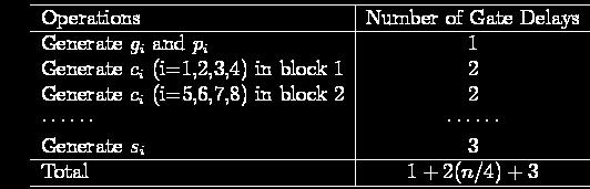
25 Complete Circuit Delays
26 Two Level
27 To do Read up hierarchical adders. Read notes on Carry-Save adder.
28 STATE REDUCTION
29 Overview Important to minimize the size of digital circuitry Analysis of state machines leads to a state table (or diagram) In many cases reducing the number of states reduces the number of gates and flops This is not true 100% of the time In this course we attempt state reduction by examining the state table Other, more advanced approaches, possible Reducing the number of states generally reduces complexity.
30 FSM Comparison Solution A Moore Machine output function only of PS maybe more state synchronous outputs no glitching one cycle delay full cycle of stable output Solution B Mealy Machine output function of both PS & input maybe fewer states asynchronous outputs if input glitches, so does output output immediately available output may not be stable long enough to be useful:
31 FSM Recap Moore Machine Mealy Machine Both machine types allow one-hot implementations.
32 FSM Optimization State Reduction: Motivation: lower cost fewer flip-flops in one-hot implementations possibly fewer flip-flops in encoded implementations more don t cares in next state logic fewer gates in next state logic Simpler to design with extra states then reduce later. Example: Odd parity checker Moore machine
33 State Reduction Row Matching is based on the state-transition table: If two states have the same output and both transition to the same next state or both transition to each other or both self-loop then they are equivalent. Combine the equivalent states into a new renamed state. Repeat until no more states are combined State Transition Table NS output PS x=0 x=1 S0 S0 S1 0 S1 S1 S2 1 S2 S2 S1 0
34 FSM Optimization Merge state S2 into S0 Eliminate S2 New state machine shows same I/O behavior Example: Odd parity checker. State Transition Table NS output PS x=0 x=1 S0 S0 S1 0 S1 S1 S0 1
35 Row Matching Example (Mealy) State Transition Table NS output PS x=0 x=1 x=0 x=1 a a b 0 0 b c d 0 0 c a d 0 0 d e f 0 1 e a f 0 1 f g f 0 1 g a f 0 1
36 Row Matching Example NS output PS x=0 x=1 x=0 x=1 a a b 0 0 b c d 0 0 c a d 0 0 d e f 0 1 e a f 0 1 f e f 0 1 Reduced State Transition Diagram NS output PS x=0 x=1 x=0 x=1 a a b 0 0 b c d 0 0 c a d 0 0 d e d 0 1 e a d 0 1
37 Partitioning Minimization (Moore) State Transition Table NS output PS x=0 x=1 a b c 1 b d f 1 c f e 0 d b g 1 e f c 0 f e d 0 g f g 0 Step 1: P1= (abcdefg) Step 2: P2=(abd)(cefg) Step 3: (abd) 0-successors (bdb) (abd) 1-successors (cfg) (cefg) 0-successors (ffef) (cefg) 1-successors (ecdg) P3: (abd)(ceg)(f)
38 Partitioning Minimization Step 3: P3: (abd)(ceg)(f) State Transition Table NS output PS x=0 x=1 a b c 1 b d f 1 c f e 0 d b g 1 e f c 0 f e d 0 g f g 0 Step 4: (abd) 0-successors (bdb) (abd) 1-successors (cfg) b must be removed (ceg) 0-successors (fff) (ceg) 1-successors (ecg) P4: (ad)(b)(ceg)(f)
39 Partitioning Minimization Step 4: P4: (ad)(b)(ceg)(f) State Transition Table NS output PS x=0 x=1 a b c 1 b a f 1 c f c 0 f c a 0 Step 5: (verify no change)
40 STATE ASSIGNMENT
41 Encoding State Variables Option 1: Binary values 000, 001, 010, 011, 100 Option 2: Gray code 000, 001, 011, 010, 110 Option 3: One hot encoding One bit for every state Only one bit is a one at a given time For a 5-state machine 00001, 00010, 00100, 01000, 10000
42 Summary Important to create smallest possible FSMs This course: use visual inspection method Often possible to reduce logic and flip flops State encoding is important One-hot coding is popular for flip flop intensive designs.
43 SHIFT REGISTERS
44 Overview Multiple flip flops can be combined to form a data register Shift registers allow data to be transported one bit at a time Registers also allow for parallel transfer Many bits transferred at the same time Shift registers can be used with adders to build arithmetic units Remember: most digital hardware can be built from combinational logic (and, or, invert) and flip flops Basic components of most computers
45 Register with Parallel Load Register: Group of Flip-Flops Ex: D Flip-Flops Holds a Word of Data Loads in Parallel on Clock Transition Asynchronous Clear (Reset)
46 Register with Load Control Load Control = 1 New data loaded on next positive clock edge Load Control = 0 Old data reloaded on next positive clock edge
47 Shift Registers Cascade chain of Flip-Flops Bits travel on Clock edges Serial in Serial out, can also have parallel load / read


48 Parallel Data Transfer All data transfers on rising clock edge Data clocked into register Y
49 Parallel versus Serial Serial communications is defined as Provides a binary number as a sequence of binary digits, one after another, through one data line. Parallel communications Provides a binary number through multiple data lines at the same time.
50 Shift register application Parallel-to-serial conversion for serial transmission parallel outputs parallel inputs serial transmission
51 Serial Transfer Data transfer one bit at a time Data loopback for register A Time T0 T1 T2 T3 T4 Reg A Reg B
52 Serial Transfer of Data Transfer from register X to register Y (negative clock edges for this example)
53 Serial Addition (D Flip-Flop) Slower than parallel Low cost Share fast hardware on slow data
54 Serial Addition (D Flip-Flop) Only one full adder Reused for each bit Start with low-order bit addition Note that carry (Q) is saved Add multiple values. New values placed in shift register B
55 Serial Addition (D Flip-Flop) Shift control used to stop addition Generally not a good idea to gate the clock Shift register can be of arbitrary length FA is built from combin. logic
56 Universal Shift Register Clear Clock Shift Right Left Load Read Control
57 Summary Shift registers can be combined together to allow for data transfer Serial transfer used in modems and computer peripherals (e.g. mouse) D flip flops allow for a simple design Data clocked in during clock transition (rising or falling edge) Serial addition takes less chip area but is slow Universal shift register allows for many operations The register is programmable. It allows for different operations at different times Next time: counters (circuits that count!)
58 READ ONLY MEMORIES (ROM)
59 Overview Read-only memory can normally only be read Internal organization similar to SRAM ROMs are effective at implementing truth tables Any logic function can be implemented using ROMs Multiple single-bit functions embedded in a single ROM Also used in computer systems for initialization ROM doesn t lose storage value when power is removed Very useful for implementing FSMs
60 Read-Only Memory (ROM) An array of semiconductor devices diodes transistors field effect transistors 2 N words by M bits Data can be read but not changed (normal operating conditions)
61 Read-Only Memory (ROM) N input bits 2 N words by M bits Implement M arbitrary functions of N variables Example 8 words by 5 bits: 3 Input Lines A B C ROM 8 words x 5 bits F 0 F 1 F 2 F 3 F 4 5 Output Lines
62 ROM Implementation ROM = "Read Only Memory" values of memory locations are fixed ahead of time A ROM can be used to implement a truth table if the address is m-bits, we can address 2 m entries in the ROM. our outputs are the bits of data that the address points to. ROM is a combinational device, not a sequential one m n m is the "height", and n is the "width"
63 ROM Implementation Suppose there are 10 inputs 10 address lines (i.e., 2 10 = 1024 different addresses) Suppose there are 20 outputs ROM is 2 10 x 20 = 20K bits Rather wasteful, since lots of storage bits For functions, doesn t take advantage of K-maps, other minimizations
64 Read-Only Memory (ROM) Each minterm of each function can be specified 3 Inputs Lines A B C ROM 8 words x 5 bits F 0 F 1 F 2 F 3 F 4 5 Outputs Lines
65 ROM Internal Structure n Inputs Lines. n bit decoder... Memory Array 2 n words x m bits... m Outputs Lines
66 ROM Memory Array m 0 =A B C m 1 =A B C A B C 3 to 8 decoder m 2 =A BC m 3 =A BC m 4 =AB C m 5 =AB C m 6 =ABC m 7 =ABC F 0 F 1 F 2 F 3 F 4
67 Inside the ROM Alternate view Each possible horizontal/vertical intersection indicates a possible connection Or gates at bottom output the word selected by the decoder (32 x 8)
68 ROM Example Specify a truth table for a ROM which implements: F = AB + A BC G = A B C + C H = AB C + ABC + A B C
69 ROM Example Specify a truth table for a ROM which implements: F = AB + A BC G = A B C + C H = AB C + ABC + A B C
70 ROM Example Specify a truth table for a ROM which implements: F = AB + A BC G = A B C + C H = AB C + ABC + A B C
71 Function Implementation m 0 =A B C m 1 =A B C A B C 3 to 8 decoder m 2 =A BC m 3 =A BC m 4 =AB C m 5 =AB C m 6 =ABC m 7 =ABC Each column is a new function Note: two outputs unused! F G H
72 ROM Implementation of a Moore Machine ROMs implement combinational logic Note that ROMs do not hold state How would you determine the maximum clock frequency of this circuit? Look at the FF to FF path (NS to PS) Inputs ROM Next State Present State ROM Outputs
73 ROM Implementation of a Mealy Machine ROMs implement combinational logic Note that ROMs do not hold state How would you determine the maximum clock frequency of this circuit? Look at the FF to FF path (NS to PS) Inputs ROM Next State Present State ROM Outputs
74 Summary ROMs provide stable storage for data ROMs have address inputs and data outputs ROMs directly implement truth tables ROMs can be used effectively in Mealy and Moore machines to implement combinational logic In normal use ROMs are read-only They are only read, not written ROMs are often used by computers to store critical information Unlike SRAM, they maintain their storage after the power is turned off
75 PROGRAMMABLE LOGIC ARRAYS (PLA)
76 Programmable logic arrays 76 A ROM is potentially inefficient because it uses a decoder, which generates all possible minterms. No circuit minimization is done. Using a ROM to implement an n-input function requires: An n-to-2 n decoder, with n inverters and 2 n n-input AND gates. An OR gate with up to 2 n inputs. The number of gates roughly doubles for each additional ROM input.
77 Programmable logic arrays 77 A programmable logic array, or PLA, makes the decoder part of the ROM programmable too. Instead of generating all minterms, you can choose which products (not necessarily minterms) to generate.
78 78 A blank 3 x 4 x 3 PLA Inputs This is a 3 x 4 x 3 PLA (3 inputs, up to 4 product terms, and 3 outputs), ready to be programmed. OR array AND array Outputs
79 PLA example 79 x y z xy z xy x z x yz V 2 = Σm(1,2,3,4)= xy z + x z + x yz V 1 = Σm(2,6,7) = x yz + xy V 0 = Σm(4,6,7) = xy z + xy V 2 V 1 V 0
80 PLA evaluation 80 A k x m x n PLA can implement up to n functions of k inputs, each of which must be expressible with no more than m product terms. Unlike ROMs, PLAs allow you to choose which products are generated. This can significantly reduce the fan-in (number of inputs) of gates, as well as the total number of gates. However, a PLA is less general than a ROM. Not all functions may be expressible with the limited number of AND gates in a given PLA.
EECS150 - Digital Design Lecture 23 - FSMs & Counters
 EECS150 - Digital Design Lecture 23 - FSMs & Counters April 8, 2010 John Wawrzynek Spring 2010 EECS150 - Lec22-counters Page 1 One-hot encoding of states. One FF per state. State Encoding Why one-hot encoding?
FSM Optimization. Counter Logic Diagram Q1 Q2 Q3. Counter Implementation using RS FF 10/13/2015
 /3/5 CS: Digital Design http://jatinga.iitg.ernet.in/~asahu/cs FSM Optimization A. Sahu Dept of Comp. Sc. & Engg. Indian Institute of Technology Guwahati Outline Last Class: Comb. Cirt. Complexity (CCC)
ECE380 Digital Logic
 ECE38 Digital Logic State Minimization Dr. D. J. Jackson Lecture 32- State minimization For simple FSMs, it is easy to see from the state diagram that the number of states used is the minimum possible
Lecture 7: Logic design. Combinational logic circuits
 /24/28 Lecture 7: Logic design Binary digital circuits: Two voltage levels: and (ground and supply voltage) Built from transistors used as on/off switches Analog circuits not very suitable for generic
EECS150 - Digital Design Lecture 18 - Counters
 EECS150 - Digital Design Lecture 18 - Counters October 24, 2002 John Wawrzynek Fall 2002 EECS150 - Lec18-counters Page 1 Counters Special sequential circuits (FSMs) that sequence though a set outputs.
EECS150 - Digital Design Lecture 18 - Counters
 EECS50 - Digital Design Lecture 8 - Counters October 24, 2002 John Wawrzynek Fall 2002 EECS50 - Lec8-counters Page Counters Special sequential circuits (FSMs) that sequence though a set outputs. Examples:
ELEC Digital Logic Circuits Fall 2014 Sequential Circuits (Chapter 6) Finite State Machines (Ch. 7-10)
 Finite State Machines (Ch. 7-10)") ELEC 2200-002 Digital Logic Circuits Fall 2014 Sequential Circuits (Chapter 6) Finite State Machines (Ch. 7-10) Vishwani D. Agrawal James J. Danaher Professor Department of Electrical and Computer Engineering
ELEC 2200-002 Digital Logic Circuits Fall 2014 Sequential Circuits (Chapter 6) Finite State Machines (Ch. 7-10) Vishwani D. Agrawal James J. Danaher Professor Department of Electrical and Computer Engineering
 vidyarthiplus.com vidyarthiplus.com vidyarthiplus.com ANNA UNIVERSITY- COMBATORE B.E./ B.TECH. DEGREE EXAMINATION - JUNE 2009. ELECTRICAL & ELECTONICS ENGG. - FOURTH SEMESTER DIGITAL LOGIC CIRCUITS PART-A
King Fahd University of Petroleum and Minerals College of Computer Science and Engineering Computer Engineering Department
 King Fahd University of Petroleum and Minerals College of Computer Science and Engineering Computer Engineering Department Page 1 of 13 COE 202: Digital Logic Design (3-0-3) Term 112 (Spring 2012) Final
EECS150 - Digital Design Lecture 11 - Shifters & Counters. Register Summary
 EECS50 - Digital Design Lecture - Shifters & Counters February 24, 2003 John Wawrzynek Spring 2005 EECS50 - Lec-counters Page Register Summary All registers (this semester) based on Flip-flops: q 3 q 2
EECS150 - Digital Design Lecture 17 - Sequential Circuits 3 (Counters)
") EECS150 - Digital Design Lecture 17 - Sequential Circuits 3 (Counters) March 19&21, 2002 John Wawrzynek Spring 2002 EECS150 - Lec13-seq3 version 2 Page 1 Counters Special sequential circuits (FSMs) that
EECS150 - Digital Design Lecture 17 - Sequential Circuits 3 (Counters) March 19&21, 2002 John Wawrzynek Spring 2002 EECS150 - Lec13-seq3 version 2 Page 1 Counters Special sequential circuits (FSMs) that
Department of Electrical & Electronics EE-333 DIGITAL SYSTEMS
 Department of Electrical & Electronics EE-333 DIGITAL SYSTEMS 1) Given the two binary numbers X = 1010100 and Y = 1000011, perform the subtraction (a) X -Y and (b) Y - X using 2's complements. a) X = 1010100
LOGIC CIRCUITS. Basic Experiment and Design of Electronics. Ho Kyung Kim, Ph.D.
 Basic Experiment and Design of Electronics LOGIC CIRCUITS Ho Kyung Kim, Ph.D. hokyung@pusan.ac.kr School of Mechanical Engineering Pusan National University Digital IC packages TTL (transistor-transistor
EECS Components and Design Techniques for Digital Systems. FSMs 9/11/2007
 EECS 150 - Components and Design Techniques for Digital Systems FSMs 9/11/2007 Sarah Bird Electrical Engineering and Computer Sciences University of California, Berkeley Slides borrowed from David Culler
LOGIC CIRCUITS. Basic Experiment and Design of Electronics
 Basic Experiment and Design of Electronics LOGIC CIRCUITS Ho Kyung Kim, Ph.D. hokyung@pusan.ac.kr School of Mechanical Engineering Pusan National University Outline Combinational logic circuits Output
EE40 Lec 15. Logic Synthesis and Sequential Logic Circuits
 EE40 Lec 15 Logic Synthesis and Sequential Logic Circuits Prof. Nathan Cheung 10/20/2009 Reading: Hambley Chapters 7.4-7.6 Karnaugh Maps: Read following before reading textbook http://www.facstaff.bucknell.edu/mastascu/elessonshtml/logic/logic3.html
CPE100: Digital Logic Design I
 Professor Brendan Morris, SEB 3216, brendan.morris@unlv.edu CPE100: Digital Logic Design I Final Review http://www.ee.unlv.edu/~b1morris/cpe100/ 2 Logistics Tuesday Dec 12 th 13:00-15:00 (1-3pm) 2 hour
ALU, Latches and Flip-Flops
 CSE14: Components and Design Techniques for Digital Systems ALU, Latches and Flip-Flops Tajana Simunic Rosing Where we are. Last time: ALUs Plan for today: ALU example, latches and flip flops Exam #1 grades
Reg. No. Question Paper Code : B.E./B.Tech. DEGREE EXAMINATION, NOVEMBER/DECEMBER Second Semester. Computer Science and Engineering
 Sp 6 Reg. No. Question Paper Code : 27156 B.E./B.Tech. DEGREE EXAMINATION, NOVEMBER/DECEMBER 2015. Second Semester Computer Science and Engineering CS 6201 DIGITAL PRINCIPLES AND SYSTEM DESIGN (Common
Ch 7. Finite State Machines. VII - Finite State Machines Contemporary Logic Design 1
 Ch 7. Finite State Machines VII - Finite State Machines Contemporary Logic esign 1 Finite State Machines Sequential circuits primitive sequential elements combinational logic Models for representing sequential
Logic. Combinational. inputs. outputs. the result. system can
 Digital Electronics Combinational Logic Functions Digital logic circuits can be classified as either combinational or sequential circuits. A combinational circuit is one where the output at any time depends
ECEN 248: INTRODUCTION TO DIGITAL SYSTEMS DESIGN. Week 7 Dr. Srinivas Shakkottai Dept. of Electrical and Computer Engineering
 ECEN 248: INTRODUCTION TO DIGITAL SYSTEMS DESIGN Week 7 Dr. Srinivas Shakkottai Dept. of Electrical and Computer Engineering SEQUENTIAL CIRCUITS: LATCHES Overview Circuits require memory to store intermediate
University of Toronto Faculty of Applied Science and Engineering Edward S. Rogers Sr. Department of Electrical and Computer Engineering
 University of Toronto Faculty of Applied Science and Engineering Edward S. Rogers Sr. Department of Electrical and Computer Engineering Final Examination ECE 241F - Digital Systems Examiners: J. Rose and
Appendix B. Review of Digital Logic. Baback Izadi Division of Engineering Programs
 Appendix B Review of Digital Logic Baback Izadi Division of Engineering Programs bai@engr.newpaltz.edu Elect. & Comp. Eng. 2 DeMorgan Symbols NAND (A.B) = A +B NOR (A+B) = A.B AND A.B = A.B = (A +B ) OR
CPE100: Digital Logic Design I
 Professor Brendan Morris, SEB 3216, brendan.morris@unlv.edu CPE100: Digital Logic Design I Midterm02 Review http://www.ee.unlv.edu/~b1morris/cpe100/ 2 Logistics Thursday Nov. 16 th In normal lecture (13:00-14:15)
The Design Procedure. Output Equation Determination - Derive output equations from the state table
 The Design Procedure Specification Formulation - Obtain a state diagram or state table State Assignment - Assign binary codes to the states Flip-Flop Input Equation Determination - Select flipflop types
Digital Electronics Sequential Logic
 /5/27 igital Electronics Sequential Logic r. I. J. Wassell Sequential Logic The logic circuits discussed previously are known as combinational, in that the output depends only on the condition of the latest
Chapter 7. Sequential Circuits Registers, Counters, RAM
 Chapter 7. Sequential Circuits Registers, Counters, RAM Register - a group of binary storage elements suitable for holding binary info A group of FFs constitutes a register Commonly used as temporary storage
EECS150 - Digital Design Lecture 25 Shifters and Counters. Recap
 EECS150 - Digital Design Lecture 25 Shifters and Counters Nov. 21, 2013 Prof. Ronald Fearing Electrical Engineering and Computer Sciences University of California, Berkeley (slides courtesy of Prof. John
Lecture 10: Synchronous Sequential Circuits Design
 Lecture 0: Synchronous Sequential Circuits Design. General Form Input Combinational Flip-flops Combinational Output Circuit Circuit Clock.. Moore type has outputs dependent only on the state, e.g. ripple
( c) Give logic symbol, Truth table and circuit diagram for a clocked SR flip-flop. A combinational circuit is defined by the function
 Give logic symbol, Truth table and circuit diagram for a clocked SR flip-flop. A combinational circuit is defined by the function") Question Paper Digital Electronics (EE-204-F) MDU Examination May 2015 1. (a) represent (32)10 in (i) BCD 8421 code (ii) Excess-3 code (iii) ASCII code (b) Design half adder using only NAND gates. ( c)
Question Paper Digital Electronics (EE-204-F) MDU Examination May 2015 1. (a) represent (32)10 in (i) BCD 8421 code (ii) Excess-3 code (iii) ASCII code (b) Design half adder using only NAND gates. ( c)
Fundamentals of Computer Systems
 Fundamentals of Computer Systems Review for the Final Stephen A. Edwards Columbia University Summer 25 The Final 2 hours 8 problems Closed book Simple calculators are OK, but unnecessary One double-sided
CSE140: Components and Design Techniques for Digital Systems. Midterm Information. Instructor: Mohsen Imani. Sources: TSR, Katz, Boriello & Vahid
 CSE140: Components and Design Techniques for Digital Systems Midterm Information Instructor: Mohsen Imani Midterm Topics In general: everything that was covered in homework 1 and 2 and related lectures,
Sequential Logic Worksheet
 Sequential Logic Worksheet Concept Inventory: Notes: D-latch & the Dynamic Discipline D-register Timing constraints for sequential circuits Set-up and hold times for sequential circuits 6.004 Worksheet
Philadelphia University Student Name: Student Number:
 Philadelphia University Student Name: Student Number: Faculty of Engineering Serial Number: Final Exam, Second Semester: 2015/2016 Dept. of Computer Engineering Course Title: Logic Circuits Date: 08/06/2016
Models for representing sequential circuits
 Sequential Circuits Models for representing sequential circuits Finite-state machines (Moore and Mealy) Representation of memory (states) Changes in state (transitions) Design procedure State diagrams
Synchronous Sequential Logic
 1 IT 201 DIGITAL SYSTEMS DESIGN MODULE4 NOTES Synchronous Sequential Logic Sequential Circuits - A sequential circuit consists of a combinational circuit and a feedback through the storage elements in
Fundamentals of Computer Systems
 Fundamentals of Computer Systems Review for the Midterm Stephen A. Edwards Columbia University Spring 22 The Midterm 75 minutes 4 5 problems Closed book Simple calculators are OK, but unnecessary One double-sided
Timing Constraints in Sequential Designs. 63 Sources: TSR, Katz, Boriello & Vahid
 Timing Constraints in Sequential esigns 63 Sources: TSR, Katz, Boriello & Vahid Where we are now. What we covered last time: FSMs What we ll do next: Timing constraints Upcoming deadlines: ZyBook today:
EEE2135 Digital Logic Design
 EEE2135 Digital Logic Design Chapter 7. Sequential Circuits Design 서강대학교 전자공학과 1. Model of Sequential Circuits 1) Sequential vs. Combinational Circuits a. Sequential circuits: Outputs depend on both the
Digital Electronics Circuits 2017
 JSS SCIENCE AND TECHNOLOGY UNIVERSITY Digital Electronics Circuits (EC37L) Lab in-charge: Dr. Shankraiah Course outcomes: After the completion of laboratory the student will be able to, 1. Simplify, design
Review for B33DV2-Digital Design. Digital Design
 Review for B33DV2 The Elements of Modern Behaviours Design Representations Blocks Waveforms Gates Truth Tables Boolean Algebra Switches Rapid Prototyping Technologies Circuit Technologies TTL MOS Simulation
Computer Science 324 Computer Architecture Mount Holyoke College Fall Topic Notes: Digital Logic
 Computer Science 324 Computer Architecture Mount Holyoke College Fall 2007 Topic Notes: Digital Logic Our goal for the next few weeks is to paint a a reasonably complete picture of how we can go from transistor
Show that the dual of the exclusive-or is equal to its compliment. 7
 Darshan Institute of ngineering and Technology, Rajkot, Subject: Digital lectronics (2300) GTU Question ank Unit Group Questions Do as directed : I. Given that (6)0 = (00)x, find the value of x. II. dd
Sample Test Paper - I
 Scheme G Sample Test Paper - I Course Name : Computer Engineering Group Marks : 25 Hours: 1 Hrs. Q.1) Attempt any THREE: 09 Marks a) Define i) Propagation delay ii) Fan-in iii) Fan-out b) Convert the following:
IE1204 Digital Design. L10: State Machines (Part 2) Masoumeh (Azin) Ebrahimi Elena Dubrova
 Masoumeh (Azin) Ebrahimi Elena Dubrova") IE1204 Digital Design L10: State Machines (Part 2) Masoumeh (Azin) Ebrahimi (masebr@kth.se) Elena Dubrova (dubrova@kth.se) KTH / ICT / ES This lecture BV pp. 528-532, 557-567 IE1204 Digital Design, Autumn2015
IE1204 Digital Design L10: State Machines (Part 2) Masoumeh (Azin) Ebrahimi (masebr@kth.se) Elena Dubrova (dubrova@kth.se) KTH / ICT / ES This lecture BV pp. 528-532, 557-567 IE1204 Digital Design, Autumn2015
Fundamentals of Digital Design
 Fundamentals of Digital Design Digital Radiation Measurement and Spectroscopy NE/RHP 537 1 Binary Number System The binary numeral system, or base-2 number system, is a numeral system that represents numeric
Introduction EE 224: INTRODUCTION TO DIGITAL CIRCUITS & COMPUTER DESIGN. Lecture 6: Sequential Logic 3 Registers & Counters 5/9/2010
 EE 224: INTROUCTION TO IGITAL CIRCUITS & COMPUTER ESIGN Lecture 6: Sequential Logic 3 Registers & Counters 05/10/2010 Avinash Kodi, kodi@ohio.edu Introduction 2 A Flip-Flop stores one bit of information
Adders allow computers to add numbers 2-bit ripple-carry adder
 Lecture 12 Logistics HW was due yesterday HW5 was out yesterday (due next Wednesday) Feedback: thank you! Things to work on: ig picture, ook chapters, Exam comments Last lecture dders Today Clarification
Chapter 5. Digital Design and Computer Architecture, 2 nd Edition. David Money Harris and Sarah L. Harris. Chapter 5 <1>
 Chapter 5 Digital Design and Computer Architecture, 2 nd Edition David Money Harris and Sarah L. Harris Chapter 5 Chapter 5 :: Topics Introduction Arithmetic Circuits umber Systems Sequential Building
University of Toronto Faculty of Applied Science and Engineering Edward S. Rogers Sr. Department of Electrical and Computer Engineering
 University of Toronto Faculty of Applied Science and Engineering Edward S. Rogers Sr. Department of Electrical and Computer Engineering Final Examination ECE 241F - Digital Systems Examiners: S. Brown,
CPE/EE 422/522. Chapter 1 - Review of Logic Design Fundamentals. Dr. Rhonda Kay Gaede UAH. 1.1 Combinational Logic
 CPE/EE 422/522 Chapter - Review of Logic Design Fundamentals Dr. Rhonda Kay Gaede UAH UAH Chapter CPE/EE 422/522. Combinational Logic Combinational Logic has no control inputs. When the inputs to a combinational
FSM model for sequential circuits
 1 FSM model for sequential circuits The mathematical model of a sequential circuit is called finite-state machine. FSM is fully characterized by: S Finite set of states ( state ~ contents of FFs) I Finite
EECS150 - Digital Design Lecture 16 Counters. Announcements
 EECS150 - Digital Design Lecture 16 Counters October 20, 2011 Elad Alon Electrical Engineering and Computer Sciences University of California, Berkeley http://www-inst.eecs.berkeley.edu/~cs150 Fall 2011
S.Y. Diploma : Sem. III [DE/ED/EI/EJ/EN/ET/EV/EX/IC/IE/IS/IU/MU] Principles of Digital Techniques
![S.Y. Diploma : Sem. III [DE/ED/EI/EJ/EN/ET/EV/EX/IC/IE/IS/IU/MU] Principles of Digital Techniques](/thumbs/82/86792063.jpg "S.Y. Diploma : Sem. III [DE/ED/EI/EJ/EN/ET/EV/EX/IC/IE/IS/IU/MU] Principles of Digital Techniques") S.Y. Diploma : Sem. III [DE/ED/EI/EJ/EN/ET/EV/EX/IC/IE/IS/IU/MU] Principles of Digital Techniques Time: 3 Hrs.] Prelim Question Paper Solution [Marks : 100 Q.1(a) Attempt any SIX of the following : [12]
S.Y. Diploma : Sem. III [DE/ED/EI/EJ/EN/ET/EV/EX/IC/IE/IS/IU/MU] Principles of Digital Techniques Time: 3 Hrs.] Prelim Question Paper Solution [Marks : 100 Q.1(a) Attempt any SIX of the following : [12]
Clocked Sequential Circuits UNIT 13 ANALYSIS OF CLOCKED SEQUENTIAL CIRCUITS. Analysis of Clocked Sequential Circuits. Signal Tracing and Timing Charts
 ed Sequential Circuits 2 Contents nalysis by signal tracing & timing charts State tables and graphs General models for sequential circuits sequential parity checker Reading Unit 3 asic unit Unit : Latch
Principles of Computer Architecture. Appendix B: Reduction of Digital Logic. Chapter Contents
 B-1 Principles of Computer Architecture Miles Murdocca and Vincent Heuring Appendix B: Reduction of Digital Logic B-2 Chapter Contents B.1 Reduction of Combinational Logic and Sequential Logic B.2 Reduction
PAST EXAM PAPER & MEMO N3 ABOUT THE QUESTION PAPERS:
 EKURHULENI TECH COLLEGE. No. 3 Mogale Square, Krugersdorp. Website: www. ekurhulenitech.co.za Email: info@ekurhulenitech.co.za TEL: 011 040 7343 CELL: 073 770 3028/060 715 4529 PAST EXAM PAPER & MEMO N3
Review: Designing with FSM. EECS Components and Design Techniques for Digital Systems. Lec 09 Counters Outline.
 Review: esigning with FSM EECS 150 - Components and esign Techniques for igital Systems Lec 09 Counters 9-28-0 avid Culler Electrical Engineering and Computer Sciences University of California, Berkeley
Problem Set 9 Solutions
 CSE 26 Digital Computers: Organization and Logical Design - 27 Jon Turner Problem Set 9 Solutions. For each of the sequential circuits shown below, draw in the missing parts of the timing diagrams. You
DHANALAKSHMI COLLEGE OF ENGINEERING, CHENNAI DEPARTMENT OF COMPUTER SCIENCE AND ENGINEERING CS6201 DIGITAL PRINCIPLES AND SYSTEM DESIGN
 DHANALAKSHMI COLLEGE OF ENGINEERING, CHENNAI DEPARTMENT OF COMPUTER SCIENCE AND ENGINEERING CS6201 DIGITAL PRINCIPLES AND SYSTEM DESIGN UNIT I : BOOLEAN ALGEBRA AND LOGIC GATES PART - A (2 MARKS) Number
Synchronous Sequential Circuit Design. Digital Computer Design
 Synchronous Sequential Circuit Design Digital Computer Design Races and Instability Combinational logic has no cyclic paths and no races If inputs are applied to combinational logic, the outputs will always
DE58/DC58 LOGIC DESIGN DEC 2014
 Q.2 a. In a base-5 number system, 3 digit representations is used. Find out (i) Number of distinct quantities that can be represented.(ii) Representation of highest decimal number in base-5. Since, r=5
Fundamentals of Boolean Algebra
 UNIT-II 1 Fundamentals of Boolean Algebra Basic Postulates Postulate 1 (Definition): A Boolean algebra is a closed algebraic system containing a set K of two or more elements and the two operators and
3. Complete the following table of equivalent values. Use binary numbers with a sign bit and 7 bits for the value
 EGC22 Digital Logic Fundamental Additional Practice Problems. Complete the following table of equivalent values. Binary. Octal 35.77 33.23.875 29.99 27 9 64 Hexadecimal B.3 D.FD B.4C 2. Calculate the following
Parity Checker Example. EECS150 - Digital Design Lecture 9 - Finite State Machines 1. Formal Design Process. Formal Design Process
 Parity Checker Example A string of bits has even parity if the number of 1 s in the string is even. Design a circuit that accepts a bit-serial stream of bits and outputs a 0 if the parity thus far is even
10/12/2016. An FSM with No Inputs Moves from State to State. ECE 120: Introduction to Computing. Eventually, the States Form a Loop
 University of Illinois at Urbana-Champaign Dept. of Electrical and Computer Engineering An FSM with No Inputs Moves from State to State What happens if an FSM has no inputs? ECE 120: Introduction to Computing
WORKBOOK. Try Yourself Questions. Electrical Engineering Digital Electronics. Detailed Explanations of
 27 WORKBOOK Detailed Eplanations of Try Yourself Questions Electrical Engineering Digital Electronics Number Systems and Codes T : Solution Converting into decimal number system 2 + 3 + 5 + 8 2 + 4 8 +
Sequential Logic. Road Traveled So Far
 Comp 2 Spring 25 2/ Lecture page Sequential Logic These must be the slings and arrows of outrageous fortune ) Synchronous as an implementation of Sequential 2) Synchronous Timing Analysis 3) Single synchronous
Vidyalankar S.E. Sem. III [CMPN] Digital Logic Design and Analysis Prelim Question Paper Solution
![Vidyalankar S.E. Sem. III [CMPN] Digital Logic Design and Analysis Prelim Question Paper Solution](/thumbs/90/103673562.jpg "Vidyalankar S.E. Sem. III [CMPN] Digital Logic Design and Analysis Prelim Question Paper Solution") . (a) (i) ( B C 5) H (A 2 B D) H S.E. Sem. III [CMPN] Digital Logic Design and Analysis Prelim Question Paper Solution ( B C 5) H (A 2 B D) H = (FFFF 698) H (ii) (2.3) 4 + (22.3) 4 2 2. 3 2. 3 2 3. 2 (2.3)
. (a) (i) ( B C 5) H (A 2 B D) H S.E. Sem. III [CMPN] Digital Logic Design and Analysis Prelim Question Paper Solution ( B C 5) H (A 2 B D) H = (FFFF 698) H (ii) (2.3) 4 + (22.3) 4 2 2. 3 2. 3 2 3. 2 (2.3)
DIGITAL LOGIC CIRCUITS
 DIGITAL LOGIC CIRCUITS Introduction Logic Gates Boolean Algebra Map Specification Combinational Circuits Flip-Flops Sequential Circuits Memory Components Integrated Circuits Digital Computers 2 LOGIC GATES
Boolean Algebra and Digital Logic 2009, University of Colombo School of Computing
 IT 204 Section 3.0 Boolean Algebra and Digital Logic Boolean Algebra 2 Logic Equations to Truth Tables X = A. B + A. B + AB A B X 0 0 0 0 3 Sum of Products The OR operation performed on the products of
3 Logic Function Realization with MSI Circuits
 3 Logic Function Realization with MSI Circuits Half adder A half-adder is a combinational circuit with two binary inputs (augund and addend bits) and two binary outputs (sum and carry bits). It adds the
14.1. Unit 14. State Machine Design
 4. Unit 4 State Machine Design 4.2 Outcomes I can create a state diagram to solve a sequential problem I can implement a working state machine given a state diagram STATE MACHINES OVERVIEW 4.3 4.4 Review
Let s now begin to formalize our analysis of sequential machines Powerful methods for designing machines for System control Pattern recognition Etc.
 Finite State Machines Introduction Let s now begin to formalize our analysis of sequential machines Powerful methods for designing machines for System control Pattern recognition Etc. Such devices form
Example: vending machine
 Example: vending machine Release item after 15 cents are deposited Single coin slot for dimes, nickels o change Reset Coin Sensor Vending Machine FSM Open Release Mechanism Clock Spring 2005 CSE370 - guest
Lecture A: Logic Design and Gates
 Lecture A: Logic Design and Gates Syllabus My office hours 9.15-10.35am T,Th or gchoi@ece.tamu.edu 333G WERC Text: Brown and Vranesic Fundamentals of Digital Logic,» Buy it.. Or borrow it» Other book:
Sequential vs. Combinational
 Sequential Circuits Sequential vs. Combinational Combinational Logic: Output depends only on current input TV channel selector (-9) inputs system outputs Sequential Logic: Output depends not only on current
Memory, Latches, & Registers
 Memory, Latches, & Registers 1) Structured Logic Arrays 2) Memory Arrays 3) Transparent Latches 4) How to save a few bucks at toll booths 5) Edge-triggered Registers L13 Memory 1 General Table Lookup Synthesis
Review: Designing with FSM. EECS Components and Design Techniques for Digital Systems. Lec09 Counters Outline.
 Review: Designing with FSM EECS 150 - Components and Design Techniques for Digital Systems Lec09 Counters 9-28-04 David Culler Electrical Engineering and Computer Sciences University of California, Berkeley
COMBINATIONAL LOGIC FUNCTIONS
 COMBINATIONAL LOGIC FUNCTIONS Digital logic circuits can be classified as either combinational or sequential circuits. A combinational circuit is one where the output at any time depends only on the present
Lecture 3 Review on Digital Logic (Part 2)
") Lecture 3 Review on Digital Logic (Part 2) Xuan Silvia Zhang Washington University in St. Louis http://classes.engineering.wustl.edu/ese461/ ircuit Optimization Simplest implementation ost criterion literal
Lecture 3 Review on Digital Logic (Part 2) Xuan Silvia Zhang Washington University in St. Louis http://classes.engineering.wustl.edu/ese461/ ircuit Optimization Simplest implementation ost criterion literal
ELCT201: DIGITAL LOGIC DESIGN
 ELCT201: DIGITAL LOGIC DESIGN Dr. Eng. Haitham Omran, haitham.omran@guc.edu.eg Dr. Eng. Wassim Alexan, wassim.joseph@guc.edu.eg Following the slides of Dr. Ahmed H. Madian Lecture 10 محرم 1439 ه Winter
Homework Assignment #1 Solutions EE 477 Spring 2017 Professor Parker
 Homework Assignment #1 Solutions EE 477 Spring 2017 Professor Parker Note: + implies OR,. implies AND, ~ implies NOT Question 1: a) (4%) Use transmission gates to design a 3-input OR gate Note: There are
For smaller NRE cost For faster time to market For smaller high-volume manufacturing cost For higher performance
 University of California at Berkeley College of Engineering Department of Electrical Engineering and Computer Sciences EECS5 J. Wawrzynek Spring 22 2/22/2. [2 pts] Short Answers. Midterm Exam I a) [2 pts]
Counters. We ll look at different kinds of counters and discuss how to build them
 Counters We ll look at different kinds of counters and discuss how to build them These are not only examples of sequential analysis and design, but also real devices used in larger circuits 1 Introducing
ECE/Comp Sci 352 Digital Systems Fundamentals. Charles R. Kime Section 2 Fall Logic and Computer Design Fundamentals
 University of Wisconsin - Madison ECE/Comp Sci 352 Digital Systems Fundamentals Charles R. Kime Section 2 Fall 2001 Lecture 5 Registers & Counters Part 2 Charles Kime Counters Counters are sequential circuits
King Fahd University of Petroleum and Minerals College of Computer Science and Engineering Computer Engineering Department
 King Fahd University of Petroleum and Minerals College of Computer Science and Engineering Computer Engineering Department Page of COE 22: Digital Logic Design (3--3) Term (Fall 22) Final Exam Sunday January
Chapter 3. Digital Design and Computer Architecture, 2 nd Edition. David Money Harris and Sarah L. Harris. Chapter 3 <1>
 Chapter 3 Digital Design and Computer Architecture, 2 nd Edition David Money Harris and Sarah L. Harris Chapter 3 Chapter 3 :: Topics Introduction Latches and Flip-Flops Synchronous Logic Design Finite
SAU1A FUNDAMENTALS OF DIGITAL COMPUTERS
 SAU1A FUNDAMENTALS OF DIGITAL COMPUTERS Unit : I - V Unit : I Overview Fundamentals of Computers Characteristics of Computers Computer Language Operating Systems Generation of Computers 2 Definition of
CHAPTER 7. Exercises 17/ / /2 2 0
 CHAPTER 7 Exercises E7. (a) For the whole part, we have: Quotient Remainders 23/2 /2 5 5/2 2 2/2 0 /2 0 Reading the remainders in reverse order, we obtain: 23 0 = 0 2 For the fractional part we have 2
Latches. October 13, 2003 Latches 1
 Latches The second part of CS231 focuses on sequential circuits, where we add memory to the hardware that we ve already seen. Our schedule will be very similar to before: We first show how primitive memory
Digital Logic and Design (Course Code: EE222) Lecture 19: Sequential Circuits Contd..
 Lecture 19: Sequential Circuits Contd..") Indian Institute of Technology Jodhpur, Year 2017-2018 Digital Logic and Design (Course Code: EE222) Lecture 19: Sequential Circuits Contd.. Course Instructor: Shree Prakash Tiwari Email: sptiwari@iitj.ac.in
Indian Institute of Technology Jodhpur, Year 2017-2018 Digital Logic and Design (Course Code: EE222) Lecture 19: Sequential Circuits Contd.. Course Instructor: Shree Prakash Tiwari Email: sptiwari@iitj.ac.in
Sequential Logic Design: Controllers
 Sequential Logic Design: Controllers Controller Design, Flip Flop Timing Copyright (c) 2012 Sean Key Standard Controller Architecture Controller A circuit that implements a FSM is referred to as a controller
Different encodings generate different circuits
 FSM State Encoding Different encodings generate different circuits no easy way to find best encoding with fewest logic gates or shortest propagation delay. Binary encoding: K states need log 2 K bits i.e.,
BER KELEY D AV IS IR VINE LOS AN GELES RIVERS IDE SAN D IEGO S AN FRANCISCO
 UN IVERSIT Y O F CA LIFO RNI A AT BERKELEY BER KELEY D AV IS IR VINE LOS AN GELES RIVERS IDE SAN D IEGO S AN FRANCISCO SAN TA BARBA RA S AN TA CRUZ De p a r tm en t of Ele ctr i ca l En gin e e rin g a
COEN 312 DIGITAL SYSTEMS DESIGN - LECTURE NOTES Concordia University
 1 OEN 312 DIGIAL SYSEMS DESIGN - LEURE NOES oncordia University hapter 6: Registers and ounters NOE: For more examples and detailed description of the material in the lecture notes, please refer to the
University of Toronto Faculty of Applied Science and Engineering Final Examination
 University of Toronto Faculty of Applied Science and Engineering Final Examination ECE 24S - Digital Systems Examiner: Belinda Wang, Jianwen Zhu 2: - 4:3pm, April 26th, 24 Duration: 5 minutes (2.5 hours)
Combinational Logic. Mantıksal Tasarım BBM231. section instructor: Ufuk Çelikcan
 Combinational Logic Mantıksal Tasarım BBM23 section instructor: Ufuk Çelikcan Classification. Combinational no memory outputs depends on only the present inputs expressed by Boolean functions 2. Sequential
CS470: Computer Architecture. AMD Quad Core
 CS470: Computer Architecture Yashwant K. Malaiya, Professor malaiya@cs.colostate.edu AMD Quad Core 1 Architecture Layers Building blocks Gates, flip-flops Functional bocks: Combinational, Sequential Instruction