Lecture 14 Advanced Photolithography
|
|
|
- Bernard Dalton
- 6 years ago
- Views:
Transcription
1 Lecture 14 Advanced Photolithography Chapter 14 Wolf and Tauber 1/74
2 Announcements Term Paper: You are expected to produce a 4-5 page term paper on a selected topic (from a list). Term paper contributes 25% of course grade. You should have all been assigned your first-choice topic. The term paper should be handed in at the start of class on Tuesday 21 st November. Details / regulations are on the course website. The term paper will be returned to you in class on Thursday 30 th November. 2/74
3 Useful Links UT-Austin: Review Article on Immersion Lithography: Review Article on Extreme ultraviolet lithography: Review Article on Electron-Beam Lithography: Review Article on Nanoimprint Lithography: 3/74
4 Lecture 14 Review of Lecture 13 Improving Resolution of Optical Lithography. Extreme UV-Lithography. Electron Beam Lithography. Nanoimprint Lithography. 4/74
5 Review of Optical Photolithography 5/74
6 Apply The Photolithography Process Apply photoresist. Expose photoresist through a patterned mask or reticle. Develop PR by immersing it in a solvent which preferentially dissolves the PR of higher solubility. Process the exposed part of the wafer. Strip away the remaining photoresist. Inspect pattern. PR Substrate Mask Strip Etch Develop Expose 6/74


7 Photoresist Deposition Industrially this is done with robotic arms and automated dispensers: Extremely uniform films can be deposited using spin coating (rms roughness ~ Å s) 7/74
8 Exposure Techniques Three approaches are typically taken to exposure: Contact Printing Mask Defects Bowing of mask 1:1 Printing Proximity Printing 2-4 μm resolution Mask space ( 25 mm) Mask lens 2-5 X reduction Printing System Magn. Resolution (μm) Use Contact Research Proximity Low Cost Projection Mainstream VLSI Projection Printing 8/74
9 Fraunhofer Diffraction The resolution in Fraunhofer diffraction is defined by the Rayleigh criterion. Rayleigh Criterion: when the peak of one projection lands on the first zero of the other: 9/74
10 Modulation Transfer Function Intensity at Mask 1 Intensity on wafer 1 I Max I Min 0 Position 0 Position We define MTF: MTF = I max I min I max + I min MTF is defined between 0 (small features) and 1 (large features). Generally, MTF needs to be > 0.5 for the resist to resolve features. 10/74
11 Improving Resolution of Optical Lithography 11/74
12 Optical Lithography State of the Art as of 2009: Half-pitch (half of distance between elements) 12/74

13 Optical Lithography State of the Art as of 2009: 13/74
14 Optical Lithography The next generation of lithography will likely achieved via one of the following approaches: Extreme ultraviolet (EUV) lithography. Electron beam lithography (EPL). Nanoimprint Imprint lithography (NIL). λ ~ nm. However, because of existing infrastructure, it is likely that 193nm-based optical technology will be extended as far as possible. There are a number of techniques that optical lithography can be improved. 14/74
15 Optical Proximity Correction Optical Proximity Correction (OPC): Clever mask engineering based on software algorithms can compensate some of this error. This requires sophisticated computer modeling. 15/74

16 OPC Examples 16/74
17 Phase Shift Masks Until now we talked just about intensity (I) on the light on the mask or wafer. But the wave has an a amplitude, E, which can be negative, positive (or complex). E x, t = A cos kx ωt θ The intensity is the square of the amplitude I = E 2 17/74
18 Phase Shift Masks Masks can be manufactured (albeit expensively) to shift the phase of the light: Mask Amplitude At Wafer 180 o phase shift Intensity 18/74

19 Multilayer Resist Processing Multilayer resists are a way to address depth of focus and modulation issues. E.g. bilayer: Layer to be processed (e.g. etched) Contrast enhancement layer ( nm) Conventional photoresist Substrate The Contrast enhancement layer is photo-bleachable layer, and will change its optical transmittance on exposure to light. Poly(methyl methacrylate) (PMMA) is often employed here: 19/74
20 Multilayer Resist Processing Conventional photoresist Contrast enhancement layer Mask lens Exposed regions become transparent to UV light The top layer (e.g. PMMA) now acts as a contact mask. Without the problems due to metal contamination. 20/74
21 Multilayer Resist Processing Bilayer resists cannot measurably improve resolution. Image on PMMA remains limited by projection printing. Contrast enhancement can improve modulation: Intensity on PMMA 1 I Max Intensity on Wafer 1 I Min 0 Position 0 Position 21/74
.")
22 Multilayer Resist Processing Example of results: Advantages of bilayer processing: Better modulation. Disadvantages of bilayer processing: Increased complexity (cost). 22/74


23 Multilayer Resist Processing Another example is self-aligned sidewall patterning: Reactive ion etch 23/74
24 Multilayer Resist Processing Advantages of self-aligned sidewall patterning: Low cost. High resolution. Disadvantages of self-aligned sidewall patterning: Every feature will have the same linewidth Will create loops. 24/74

25 Multilayer Resist Processing There are many approaches to multi-layer patterning: 25/74
26 Immersion Lithography Recall that for projection printing the resolution is quantified via the Rayleigh Criterion: f = Focal length R = k 1 λ f d d = Lens diameter k 1 is an experimental parameter associated with the system and resist (0.6 <k 1 < 0.8). Alternatively: NA = d f = nsinα α = maximum half angle of incident light: Numerical aperture R = k 1λ NA n = index of refraction (1 in air). α = Maximum half-angle 26/74
27 Immersion Lithography The resolution (Rayleigh Criterion) is inversely proportional to the numerical aperture: R 1 NA NA = nsinα R 1 n So can we increase the refractive index of the medium to improve the resolution? This would be equivalent to reducing the wavelength. This is the approach taken in immersion lithography. 27/74


28 Immersion Lithography The wafer is direction in contact with liquid, which is directly in contact with lens. 28/74

29 Immersion Lithography The basic operation is shown below: Refractive index of air Refractive index of lens n g Refractive index of fluid n 0 Refractive index of resist n f n r The maximum resolution for a system is determined by the lowest refractive index in the glass/fluid/resist stack. Often this is the fluid. 29/74
30 Immersion Lithography If the fluid does have the lowest refractive index, the resolution and depth of focus are given by: R = k 1λ NA = k 1λ n f sinα δ = k 2λ NA 2 = k 2 λ n f sinα 2 Or more generally: R = k 1λ nsinα δ = k 2λ nsinα 2 Where: Refractive index of lens Refractive index of fluid n = Min(n g, n f, n r ) Refractive index of resist 30/74
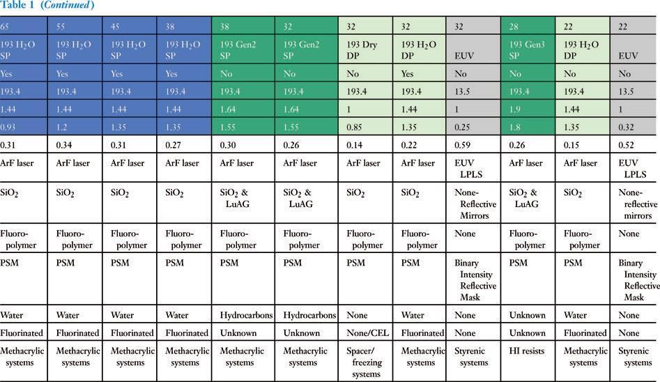
31 Immersion Lithography Some refractive indices: Material Use Refractive Index SiO 2 Oxide (to etch) 1.56 CaF 2 Lens (for UV) 1.51 Water Immersion Fluid Various Resists Resist ~ /74
32 Example The best conditions for conventional lithography are typically around the following: k 1 = 0.3. sinα = 0.9. λ = 193 nm (ArF). What improvement in resolution would we expect when employing water-based immersion lithography. First determine resolution with standard lithography: R = k 1λ nsinα = = 64 nm Refractive index of air 32/74
33 Example If we use immersion lithography, then we first determine the minimum refractive index: Below the resist is not considered Material Use Refractive Index SiO 2 Oxide (to etch) 1.56 CaF 2 Lens (for UV) 1.51 Water Immersion Fluid Various Resists Resist ~1.70 n = Min(n g, n f, n r ) n = Min(1.51, 1.435,1.70) n = We then proceed as before: 33/74
34 Example All other conditions are the same: k 1 = 0.3. sinα = 0.9. λ = 193 nm (ArF). R = k 1λ nsinα = = 45 nm Refractive index of water This gets us down to 45nm feature size. But for VLSI we now need 22nm (or lower)! 34/74
35 Going Below 45nm We are limited by the minimum refractive index. So we need to increase the refractive of all components together. However we also need the materials to be transparent to UV light (193 nm). Candidate lenses: Material Use Refractive Index CaF 2 Lens 1.51 BaLiF 3 Lens 1.64 Lu 3 Al 5 O 12 - LuAG Lens 2.1 Mg 3 AlSi 3 O 12 Pyrope Lens 2.0 So, we can find lenses which will not be the limiting factor. 35/74
36 Going Below 45nm Immersion Liquid: 36/74
37 Summary of Immersion Liquids Nonspecific IFs Region of interest 37/74
38 Going Below 45nm The difficulty is finding the appropriate immersion fluid (IF). The best we have so far is decalin: This has a refractive index of n = R = 37nm. This is the so-called 2 nd generation IF. 38/74
39 3 rd Generation The current target with immersion lithography is 32 nm. Lens: LuAG (n = 2.1) Resist: n = 1.8. Immersion Fluid: n = 1.9. No candidate material has been for this high refractive index fluid yet. 39/74
40 Extreme UV-Lithography 40/74
41 Extreme UV Lithography (EUV) Sometimes called deep UV Lithography (DUV). As before the resolution is determined by the Rayleigh Criterion: f = Focal length d = Lens diameter R = k 1 λ f d = k 1λ NA = k 1λ nsinα The approach is to reduce wavelength. For ArF lasers λ = 193 nm. We aim for λ = 13.4 nm. Currently in development for VLSI. Numerical aperture 41/74
42 Difficulties: Photoresist: 42/74
43 Difficulties: Lenses: 43/74
44 Difficulties: Even air: 44/74

45 So we Cannot Use Lenses So we cannot use optical lenses. Mirrors have to be employed: Also need a vacuum, to avoid absorption in chamber. 45/74
/Si(4.0nm)). Mask formed by applying absorber to multilayer mirror. 46/74")
46 So we Cannot Use Lenses Multilayer high/low index mirrors used to focus light (50 double layer Mo(2.7nm)/Si(4.0nm)). Mask formed by applying absorber to multilayer mirror. 46/74
47 EUV Source The EUV source must provide sufficient power at the desired wavelength to yield an adequate wafer throughput for a lithography tool. Producing ~10nm radiation is not trivial. Options include: Laser-produced-plasma (LPP). Synchrotron radiation. High-harmonic generation with femtosecond laser pulses. X-Ray lasers. Electron beam driven radiation devices Most are not capable to W of EUV source power at acceptable manufacturing costs. 47/74
48 EUV Source The EUV source must provide sufficient power at the desired wavelength to yield an adequate wafer throughput for a lithography tool. Producing ~10nm radiation is not trivial. Options include: Laser-produced-plasma (LPP). Synchrotron radiation. High-harmonic generation with femtosecond laser pulses. X-Ray lasers. Electron beam driven radiation devices Most are not capable to W of EUV source power at acceptable manufacturing costs. 48/74
49 EUV Source Laser-produced-plasma (LPP) turns out to be the most promising source. The LPP sources are formed by focusing a pulsed (optical) laser beam onto a solid, liquid, or gas target to produce a bright spark which has broad emission from the visible to the EUV. The LPP produces a point-like source converting 0.8% - 3.8% of the incident laser power into EUV light in the required spectral bandwidth. High-repetition-rate (3 khz) pulsed laser drivers that deliver 1500 W average power to create the Xe plasma are actively being developed commercially. 49/74
50 Optics Again, because of the extreme wavelength, the choice of mirror requires careful consideration. The materials must be chosen to be highly reflective at the chosen wavelength. Bilayer Mo/Si and Mo/Be are currently most promising. Mirrors must also be extremely flat. Rms roughness λ. Typically total sum of roughness ~ 10 Å E.g. 4 mirrors 2.5Å rms roughness per mirror. 50/74
51 Masks Masking is in theory relatively straight-forward, since most solids absorb at ~13nm. Mask formed by applying absorber to multilayer mirror. Typically Al, Ti, on the mirror surface. Patterned with e-beam lithography. The challenge for EUV mask blank fabrication is defect reduction. 51/74

52 Resists There is strong attenuation of 13.4 nm in all organic resist materials. The absorption is atomic (not by the bonds), and will not convert the materials predictably. The radiation will not penetrate through a thick photoresist. Resist must also be stable in a vacuum. Organic resist can also collapse at small linewidths: Pattern collapse on a 70 nm pitch with dose of 1.65 nc/cm 52/74

53 Resists Inorganic resists are candidates E.g. HfSOx. Advantages of inorganic resists: High etch resistance. Thin layers minimize pattern collapse. High resolution and low line edge roughness. 21 nm Residual material Patterned HfSOx 50 nm 53/74
54 Electron Beam Lithography 54/74

55 Electron Beam Lithography As with EUV lithography, the purpose of e - beam lithography is to reduce the wavelength on the incident particles. λ < 1Å. So diffraction is no longer a problem. Pattern direct written into resist by scanning e-beam. Essentially is just like an SEM: On-off capability. Pixilation. Accurate Positioning. 55/74


56 Research e-beam Lithography Often a modified SEM is employed. When imaging you can damage the material being imaged when using high energies. 1nm spot size. 10nm resolution is routinely achieved. A computer is used to design patterns. PMMA is often used as a resist. 3-5 nm 56/74
. Tungsten. Lanthanum hexaboride (LaB 6 ).")


57 Sources Low energy: thermionic source (heated filament). Tungsten. Lanthanum hexaboride (LaB 6 ). High energy: field-emission source. These are reasonably complex, but basically electrons are pulled off of metal by a very large electric field. Require a high vacuum and are difficult to fabricate. 57/74
58 Electron Wavelength For low velocity electrons the wavelength would be given by the de Broglie Equation: λ = h 2m 0 ev Where: λ = Electron wavelength. h = Planck Constant. e = Charge on electron. V = Accelerating voltage. m 0 = Rest mass of electron. 58/74
59 Electron Wavelength However, at high voltages we are accelerating electrons to appreciable percentages of the speed of light. So instead we must use the relativistic equation for wavelength: Where: λ = h 2m 0 ev c = Speed of light in vacuum ev 2m 0 c 2 Relativistic correction 59/74
60 Example If we accelerate electrons with a 200kV source, what is the difference in wavelength calculated with and without considering special relativity? Start with our non-relativistic equation: λ nr = h 2m 0 ev nr for nonrelativistic V = 200 kv is the only parameter not a fundamental constant: λ nr = λ nr = m λ nr = 2.74pm V = 200 kv 60/74
61 Example Now consider relativistic equation: r for relativistic λ r = λ r = 1 + h 2m 0 ev λ r = λ nr ev 2m 0 c ev 2m 0 c λ r = /1.09 λ r = m λ r = 2.51pm 61/74
62 Example So the results are: λ nr = 2.74pm λ r = 2.51pm Hence the effect of relativity is non-negligible at these high energies. 62/74
63 Electron Column After electrons are accelerated they are directed using electromagnetic lenses. Beam blanker is used to divert the electron beam from the optical axis of the column thus preventing electrons from reaching the sample surface. Ability to focus the electron beam limits the resolution. Sample stage is moved mechanically. 63/74
64 e-beam Lithography for VLSI Advantages: No mask needed computer controlled electro-magnetic lenses define features. Extremely accurate layer registration. Diffraction effects are not a factor. Resolution is good (3-10nm in lab). Disadvantages: Extremely slow throughput (50 slower than optical lithography!). Expensive, and expensive facilities. 64/74
65 Nanoimprint Lithography 65/74
66 Nano-Imprint Lithography Nano-Imprint Lithography (NIL) is a very simple concept: A hard mold that contains nanoscale surface-relief features is pressed into a polymeric material cast on a substrate. This creates a thickness contrast in the polymeric material. A thin residual layer of polymeric material is intentionally left underneath the mold protrusions. This acts as a cushioning layer that prevents direct impact of the hard mold on the substrate. 66/74


67 Nano-Imprint Lithography It s very easy to achieve high-resolution using NIL: 67/74
68 Step-and-Flash Imprint A variation is called step and flash imprint lithography (SFIL). Uses a transparent mold and UV-curable precursor liquid to define the pattern. Can be carried out at room temperature. 68/74


69 Mold Fabrication The mold is fabricated using a combination of reactive ion etching and lift-off. The mold is formed of a hard material (such as SiO 2 ). 69/74
. Not industrially scaled (although system do exist). http://www.")
70 Nano-Imprint Lithography Advantages: Low cost of ownership (COO). High precision. Complex patterns are possible. Disadvantages: Reproducibility is low. Contamination (contact with resist). Not industrially scaled (although system do exist). 70/74
: ~nm Can be applied onto the surface of metals.")
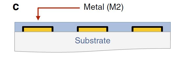
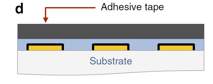
71 Adhesion Lithography One example of very low-resolution features. Employ self-assembled monolayers (SAMs): ~nm Can be applied onto the surface of metals. Self-assemble into monolayers. 71/74
72 Adhesion Lithography 72/74
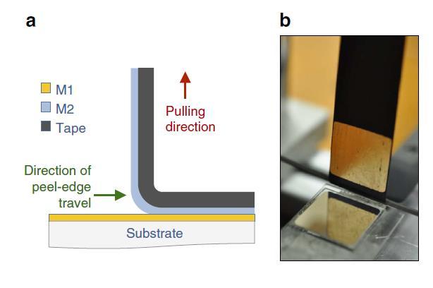
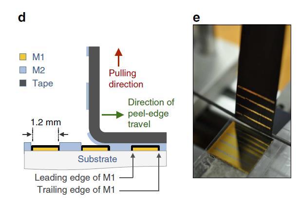
73 Adhesion Lithography 73/74

74 Adhesion Lithography 74/74
MICRO AND NANOPROCESSING TECHNOLOGIES
 LECTURE 5 MICRO AND NANOPROCESSING TECHNOLOGIES Introduction Ion lithography X-ray lithography Soft lithography E-beam lithography Concepts and processes Lithography systems Masks and resists Chapt.9.
Introduction. Photoresist : Type: Structure:
 Photoresist SEM images of the morphologies of meso structures and nanopatterns on (a) a positively nanopatterned silicon mold, and (b) a negatively nanopatterned silicon mold. Introduction Photoresist
Photolithography II ( Part 1 )
") 1 Photolithography II ( Part 1 ) Chapter 14 : Semiconductor Manufacturing Technology by M. Quirk & J. Serda Bjørn-Ove Fimland, Department of Electronics and Telecommunication, Norwegian University of Science
1 Photolithography II ( Part 1 ) Chapter 14 : Semiconductor Manufacturing Technology by M. Quirk & J. Serda Bjørn-Ove Fimland, Department of Electronics and Telecommunication, Norwegian University of Science
Nanoimprint Lithography
 Nanoimprint Lithography Wei Wu Quantum Science Research Advanced Studies HP Labs, Hewlett-Packard Email: wei.wu@hp.com Outline Background Nanoimprint lithography Thermal based UV-based Applications based
MSN551 LITHOGRAPHY II
 MSN551 Introduction to Micro and Nano Fabrication LITHOGRAPHY II E-Beam, Focused Ion Beam and Soft Lithography Why need electron beam lithography? Smaller features are required By electronics industry:
UNIT 3. By: Ajay Kumar Gautam Asst. Prof. Dev Bhoomi Institute of Technology & Engineering, Dehradun
 UNIT 3 By: Ajay Kumar Gautam Asst. Prof. Dev Bhoomi Institute of Technology & Engineering, Dehradun 1 Syllabus Lithography: photolithography and pattern transfer, Optical and non optical lithography, electron,
Overview of the main nano-lithography techniques
 Overview of the main nano-lithography techniques Soraya Sangiao sangiao@unizar.es Outline Introduction: Nanotechnology. Nano-lithography techniques: Masked lithography techniques: Photolithography. X-ray
Chapter 3 : ULSI Manufacturing Technology - (c) Photolithography
 Photolithography") Chapter 3 : ULSI Manufacturing Technology - (c) Photolithography 1 Reference 1. Semiconductor Manufacturing Technology : Michael Quirk and Julian Serda (2001) 2. - (2004) 3. Semiconductor Physics and Devices-
Chapter 3 : ULSI Manufacturing Technology - (c) Photolithography 1 Reference 1. Semiconductor Manufacturing Technology : Michael Quirk and Julian Serda (2001) 2. - (2004) 3. Semiconductor Physics and Devices-
Lecture 8. Photoresists and Non-optical Lithography
 Lecture 8 Photoresists and Non-optical Lithography Reading: Chapters 8 and 9 and notes derived from a HIGHLY recommended book by Chris Mack, Fundamental Principles of Optical Lithography. Any serious student
CURRENT STATUS OF NANOIMPRINT LITHOGRAPHY DEVELOPMENT IN CNMM
 U.S. -KOREA Forums on Nanotechnology 1 CURRENT STATUS OF NANOIMPRINT LITHOGRAPHY DEVELOPMENT IN CNMM February 17 th 2005 Eung-Sug Lee,Jun-Ho Jeong Korea Institute of Machinery & Materials U.S. -KOREA Forums
Far IR Gas Lasers microns wavelengths, THz frequency Called Terahertz lasers or FIR lasers At this wavelength behaves more like
 Far IR Gas Lasers 10-1500 microns wavelengths, 300 10 THz frequency Called Terahertz lasers or FIR lasers At this wavelength behaves more like microwave signal than light Created by Molecular vibronic
Optical Proximity Correction
 Optical Proximity Correction Mask Wafer *Auxiliary features added on mask 1 Overlay Errors + + alignment mask wafer + + photomask plate Alignment marks from previous masking level 2 (1) Thermal run-in/run-out
Nano fabrication by e-beam lithographie
 Introduction to nanooptics, Summer Term 2012, Abbe School of Photonics, FSU Jena, Prof. Thomas Pertsch Nano fabrication by e-beam lithographie Lecture 14 1 Electron Beam Lithography - EBL Introduction
Supplementary Figure 1 Detailed illustration on the fabrication process of templatestripped
 Supplementary Figure 1 Detailed illustration on the fabrication process of templatestripped gold substrate. (a) Spin coating of hydrogen silsesquioxane (HSQ) resist onto the silicon substrate with a thickness
Techniken der Oberflächenphysik (Techniques of Surface Physics)
") Techniken der Oberflächenphysik (Techniques of Surface Physics) Prof. Yong Lei & Dr. Yang Xu (& Liying Liang) Fachgebiet 3D-Nanostrukturierung, Institut für Physik Contact: yong.lei@tu-ilmenau.de; yang.xu@tu-ilmenau.de;
Techniken der Oberflächenphysik (Techniques of Surface Physics) Prof. Yong Lei & Dr. Yang Xu (& Liying Liang) Fachgebiet 3D-Nanostrukturierung, Institut für Physik Contact: yong.lei@tu-ilmenau.de; yang.xu@tu-ilmenau.de;
Photoresist Profile. Undercut: negative slope, common for negative resist; oxygen diffusion prohibits cross-linking; good for lift-off.
 Photoresist Profile 4-15 Undercut: negative slope, common for negative resist; oxygen diffusion prohibits cross-linking; good for lift-off undercut overcut Overcut: positive slope, common to positive resist,
Nanostructures Fabrication Methods
 Nanostructures Fabrication Methods bottom-up methods ( atom by atom ) In the bottom-up approach, atoms, molecules and even nanoparticles themselves can be used as the building blocks for the creation of
UNIVERSITY OF CALIFORNIA College of Engineering Department of Electrical Engineering and Computer Sciences. Fall Exam 1
 UNIVERSITY OF CALIFORNIA College of Engineering Department of Electrical Engineering and Computer Sciences EECS 143 Fall 2008 Exam 1 Professor Ali Javey Answer Key Name: SID: 1337 Closed book. One sheet
A Photonic Crystal Laser from Solution Based. Organo-Lead Iodide Perovskite Thin Films
 SUPPORTING INFORMATION A Photonic Crystal Laser from Solution Based Organo-Lead Iodide Perovskite Thin Films Songtao Chen 1, Kwangdong Roh 2, Joonhee Lee 1, Wee Kiang Chong 3,4, Yao Lu 5, Nripan Mathews
UNIVERSITY OF CALIFORNIA College of Engineering Department of Electrical Engineering and Computer Sciences. Professor Ali Javey. Fall 2009.
 UNIVERSITY OF CALIFORNIA College of Engineering Department of Electrical Engineering and Computer Sciences EE143 Professor Ali Javey Fall 2009 Exam 1 Name: SID: Closed book. One sheet of notes is allowed.
SOFT X-RAYS AND EXTREME ULTRAVIOLET RADIATION
 SOFT X-RAYS AND EXTREME ULTRAVIOLET RADIATION Principles and Applications DAVID ATTWOOD UNIVERSITY OF CALIFORNIA, BERKELEY AND LAWRENCE BERKELEY NATIONAL LABORATORY CAMBRIDGE UNIVERSITY PRESS Contents
Far IR (FIR) Gas Lasers microns wavelengths, THz frequency Called Terahertz lasers or FIR lasers At this wavelength behaves more like
 Gas Lasers microns wavelengths, THz frequency Called Terahertz lasers or FIR lasers At this wavelength behaves more like") Far IR (FIR) Gas Lasers 10-1500 microns wavelengths, 300 10 THz frequency Called Terahertz lasers or FIR lasers At this wavelength behaves more like microwave signal than light Created by Molecular vibronic
Far IR (FIR) Gas Lasers 10-1500 microns wavelengths, 300 10 THz frequency Called Terahertz lasers or FIR lasers At this wavelength behaves more like microwave signal than light Created by Molecular vibronic
Top down and bottom up fabrication
 Lecture 24 Top down and bottom up fabrication Lithography ( lithos stone / graphein to write) City of words lithograph h (Vito Acconci, 1999) 1930 s lithography press Photolithography d 2( NA) NA=numerical
Nova 600 NanoLab Dual beam Focused Ion Beam IITKanpur
 Nova 600 NanoLab Dual beam Focused Ion Beam system @ IITKanpur Dual Beam Nova 600 Nano Lab From FEI company (Dual Beam = SEM + FIB) SEM: The Electron Beam for SEM Field Emission Electron Gun Energy : 500
Visualization of Xe and Sn Atoms Generated from Laser-Produced Plasma for EUV Light Source
 3rd International EUVL Symposium NOVEMBER 1-4, 2004 Miyazaki, Japan Visualization of Xe and Sn Atoms Generated from Laser-Produced Plasma for EUV Light Source H. Tanaka, A. Matsumoto, K. Akinaga, A. Takahashi
Introduction to Photolithography
 http://www.ichaus.de/news/72 Introduction to Photolithography Photolithography The following slides present an outline of the process by which integrated circuits are made, of which photolithography is
object objective lens eyepiece lens
 Advancing Physics G495 June 2015 SET #1 ANSWERS Field and Particle Pictures Seeing with electrons The compound optical microscope Q1. Before attempting this question it may be helpful to review ray diagram
MEEN Nanoscale Issues in Manufacturing. Lithography Lecture 1: The Lithographic Process
 MEEN 489-500 Nanoscale Issues in Manufacturing Lithography Lecture 1: The Lithographic Process 1 Discuss Reading Assignment 1 1 Introducing Nano 2 2 Size Matters 3 3 Interlude One-The Fundamental Science
MASSACHUSETTS INSTITUTE OF TECHNOLOGY 6.781/2.391J TAKE-HOME FINAL ASSIGNMENT, Handed out Thursday, April 27, 2006
 MASSACHUSETTS INSTITUTE OF TECHNOLOGY 6.781/2.391J TAKE-HOME FINAL ASSIGNMENT, 2006 Handed out Thursday, April 27, 2006 Due no later than 5 PM on May 18, 2006 This is a take-home assignment. You may use
Overview of EUV Lithography and EUV Optics Contamination
 Accelerating the next technology revolution Overview of EUV Lithography and EUV Optics Contamination Andrea Wüest NIST Contamination WS Gaithersburg, MD June 2, 2009 Copyright 2008 SEMATECH, Inc. SEMATECH,
EUV lithography and Source Technology
 EUV lithography and Source Technology History and Present Akira Endo Hilase Project 22. September 2017 EXTATIC, Prague Optical wavelength and EUV (Extreme Ultraviolet) VIS 13.5nm 92eV Characteristics of
Fabrication Engineering at the Micro- and Nanoscale, by Stephen Campbell, 4 th Edition, Oxford University Press
 Fabrication Engineering at the Micro- and Nanoscale, by Stephen Campbell, 4 th Edition, Oxford University Press Errata, by Chris Mack, chris@lithoguru.com While teaching out of this book at the University
Three Approaches for Nanopatterning
 Three Approaches for Nanopatterning Lithography allows the design of arbitrary pattern geometry but maybe high cost and low throughput Self-Assembly offers high throughput and low cost but limited selections
Multilayer Interference Coating, Scattering, Diffraction, Reflectivity
 Multilayer Interference Coating, Scattering, Diffraction, Reflectivity mλ = 2d sin θ (W/C, T. Nguyen) Normal incidence reflectivity 1..5 1 nm MgF 2 /Al Si C Pt, Au 1 ev 1 ev Wavelength 1 nm 1 nm.1 nm Multilayer
Photomasks. Photolithography Evolution 9/11/2004 ECE580- MPE/MASKS/PHOTOMASKS.PPT
 Photolithography Evolution 1 : Evolution 2 Photomasks Substrates: Type : thermal expansion Chrome Pellicles Mask: OPC and PSM Fabrication: E-Beam or Laser 3 Photomask Information Websites: http://www.photronics.com/internet/corpcomm/publications/basics101/basics.
Silicon VLSI Technology. Fundamentals, Practice and Modeling
 Text Book: Silicon VLSI Technology Fundamentals, Practice and Modeling Authors: J. D. Plummer, M. D. Deal, and P. B. Griffin Photolithography (Chap. 1) Basic lithography process Apply photoresist Patterned
Lecture 20 Optical Characterization 2
 Lecture 20 Optical Characterization 2 Schroder: Chapters 2, 7, 10 1/68 Announcements Homework 5/6: Is online now. Due Wednesday May 30th at 10:00am. I will return it the following Wednesday (6 th June).
Nanotechnology Nanofabrication of Functional Materials. Marin Alexe Max Planck Institute of Microstructure Physics, Halle - Germany
 Nanotechnology Nanofabrication of Functional Materials Marin Alexe Max Planck Institute of Microstructure Physics, Halle - Germany Contents Part I History and background to nanotechnology Nanoworld Nanoelectronics
Supplementary Information Our InGaN/GaN multiple quantum wells (MQWs) based one-dimensional (1D) grating structures
 based one-dimensional (1D) grating structures") Polarized white light from hybrid organic/iii-nitrides grating structures M. Athanasiou, R. M. Smith, S. Ghataora and T. Wang* Department of Electronic and Electrical Engineering, University of Sheffield,
Polarized white light from hybrid organic/iii-nitrides grating structures M. Athanasiou, R. M. Smith, S. Ghataora and T. Wang* Department of Electronic and Electrical Engineering, University of Sheffield,
Technology for Micro- and Nanostructures Micro- and Nanotechnology
 Lecture 5: Electron-Beam Lithography, Part 1 Technology for Micro- and Nanostructures Micro- and Nanotechnology Peter Unger mailto: peter.unger @ uni-ulm.de Institute of Optoelectronics University of Ulm
Nanotechnology Fabrication Methods.
 Nanotechnology Fabrication Methods. 10 / 05 / 2016 1 Summary: 1.Introduction to Nanotechnology:...3 2.Nanotechnology Fabrication Methods:...5 2.1.Top-down Methods:...7 2.2.Bottom-up Methods:...16 3.Conclusions:...19
Introduction to Electron Beam Lithography
 Introduction to Electron Beam Lithography Boštjan Berčič (bostjan.bercic@ijs.si), Jožef Štefan Institute, Jamova 39, 1000 Ljubljana, Slovenia 1. Introduction Electron Beam Lithography is a specialized
Table of Contents. Foreword... Jörge DE SOUSA NORONHA. Introduction... Michel BRILLOUËT
 Table of Contents Foreword... Jörge DE SOUSA NORONHA Introduction... Michel BRILLOUËT xi xvii Chapter 1. Photolithography... 1 Philippe BANDELIER, Anne-Laure CHARLEY and Alexandre LAGRANGE 1.1. Introduction...
Infrastructure of Thin Films Laboratory in Institute of Molecular Physics Polish Academy of Sciences
 Infrastructure of Thin Films Laboratory in Institute of Molecular Physics Polish Academy of Sciences Outline Sample preparation Magnetron sputtering Ion-beam sputtering Pulsed laser deposition Electron-beam
Far IR (FIR) Gas Lasers microns wavelengths, THz frequency Called Terahertz lasers or FIR lasers At this wavelength behaves more like
 Gas Lasers microns wavelengths, THz frequency Called Terahertz lasers or FIR lasers At this wavelength behaves more like") Far IR (FIR) Gas Lasers 10-1500 microns wavelengths, 300 10 THz frequency Called Terahertz lasers or FIR lasers At this wavelength behaves more like microwave signal than light Created by Molecular vibronic
Far IR (FIR) Gas Lasers 10-1500 microns wavelengths, 300 10 THz frequency Called Terahertz lasers or FIR lasers At this wavelength behaves more like microwave signal than light Created by Molecular vibronic
Lecture 6 Plasmas. Chapters 10 &16 Wolf and Tauber. ECE611 / CHE611 Electronic Materials Processing Fall John Labram 1/68
 Lecture 6 Plasmas Chapters 10 &16 Wolf and Tauber 1/68 Announcements Homework: Homework will be returned to you on Thursday (12 th October). Solutions will be also posted online on Thursday (12 th October)
X-Rays From Laser Plasmas
 X-Rays From Laser Plasmas Generation and Applications I. C. E. TURCU CLRC Rutherford Appleton Laboratory, UK and J. B. DANCE JOHN WILEY & SONS Chichester New York Weinheim Brisbane Singapore Toronto Contents
Nano Materials. Nanomaterials
 Nano Materials 1 Contents Introduction Basics Synthesis of Nano Materials Fabrication of Nano Structure Nano Characterization Properties and Applications 2 Fabrication of Nano Structure Lithographic techniques
Fabrication-II. Electron Beam Lithography Pattern Design Thin Film Deposition
 Fabrication-II Electron Beam Lithography Pattern Design Thin Film Deposition By Charulata Barge, Graduate student, Prof. Zumbühl Group, Department of Physics, Universtity of Basel. Date:- 20th Oct. 2006
Photolithography 光刻 Part II: Photoresists
 微纳光电子材料与器件工艺原理 Photolithography 光刻 Part II: Photoresists Xing Sheng 盛兴 Department of Electronic Engineering Tsinghua University xingsheng@tsinghua.edu.cn 1 Photolithography 光刻胶 负胶 正胶 4 Photolithography
Pattern Transfer- photolithography
 Pattern Transfer- photolithography DUV : EUV : 13 nm 248 (KrF), 193 (ArF), 157 (F 2 )nm H line: 400 nm I line: 365 nm G line: 436 nm Wavelength (nm) High pressure Hg arc lamp emission Ref: Campbell: 7
Gaetano L Episcopo. Scanning Electron Microscopy Focus Ion Beam and. Pulsed Plasma Deposition
 Gaetano L Episcopo Scanning Electron Microscopy Focus Ion Beam and Pulsed Plasma Deposition Hystorical background Scientific discoveries 1897: J. Thomson discovers the electron. 1924: L. de Broglie propose
EUREKA: A new Industry EUV Research Center at LBNL
 EUREKA: A new Industry EUV Research Center at LBNL Patrick Naulleau Center for X-ray Optics Lawrence Berkeley National Laboratory Berkeley Lab MSD Materials Sciences Division 1 Operating model Core operational
UNIVERSITY OF CALIFORNIA College of Engineering Department of Electrical Engineering and Computer Sciences. Professor Ali Javey. Spring 2009.
 UNIVERSITY OF CALIFORNIA College of Engineering Department of Electrical Engineering and Computer Sciences EE143 Professor Ali Javey Spring 2009 Exam 1 Name: SID: Closed book. One sheet of notes is allowed.
Laser-produced extreme ultraviolet (EUV) light source plasma for the next generation lithography application
 light source plasma for the next generation lithography application") Laser-produced extreme ultraviolet (EUV) light source plasma for the next generation lithography application EUV light source plasma Tin icrodroplet Main pulse (CO2 laser pulse) Pre-pulse (Nd:YAG laser
Laser-produced extreme ultraviolet (EUV) light source plasma for the next generation lithography application EUV light source plasma Tin icrodroplet Main pulse (CO2 laser pulse) Pre-pulse (Nd:YAG laser
Lobster-Eye Hard X-Ray Telescope Mirrors
 Lobster-Eye Hard X-Ray Telescope Mirrors Victor Grubsky, Michael Gertsenshteyn, Keith Shoemaker, Igor Mariyenko, and Tomasz Jannson Physical Optics Corporation, Torrance, CA Mirror Technology Days 007
Resonator Fabrication for Cavity Enhanced, Tunable Si/Ge Quantum Cascade Detectors
 Resonator Fabrication for Cavity Enhanced, Tunable Si/Ge Quantum Cascade Detectors M. Grydlik 1, P. Rauter 1, T. Fromherz 1, G. Bauer 1, L. Diehl 2, C. Falub 2, G. Dehlinger 2, H. Sigg 2, D. Grützmacher
Sensors and Metrology. Outline
 Sensors and Metrology A Survey 1 Outline General Issues & the SIA Roadmap Post-Process Sensing (SEM/AFM, placement) In-Process (or potential in-process) Sensors temperature (pyrometry, thermocouples, acoustic
Photolithography Overview 9/29/03 Brainerd/photoclass/ECE580/Overvie w/overview
 http://www.intel.com/research/silicon/mooreslaw.htm 1 Moore s law only holds due to photolithography advancements in reducing linewidths 2 All processing to create electric components and circuits rely
Figure 1: Graphene release, transfer and stacking processes. The graphene stacking began with CVD
 Supplementary figure 1 Graphene Growth and Transfer Graphene PMMA FeCl 3 DI water Copper foil CVD growth Back side etch PMMA coating Copper etch in 0.25M FeCl 3 DI water rinse 1 st transfer DI water 1:10
Broadband transmission grating spectrometer for measuring the emission spectrum of EUV sources
 Broadband transmission grating spectrometer for measuring the emission spectrum of EUV sources Extreme ultraviolet (EUV) light sources and their optimization for emission within a narrow wavelength band
Technologies VII. Alternative Lithographic PROCEEDINGS OF SPIE. Douglas J. Resnick Christopher Bencher. Sponsored by. Cosponsored by.
 PROCEEDINGS OF SPIE Alternative Lithographic Technologies VII Douglas J. Resnick Christopher Bencher Editors 23-26 February 2015 San Jose, California, United States Sponsored by SPIE Cosponsored by DNS
Presentation Phys Katia GASPERI. Statistical study of single DNA molecules into dynamic array
 Presentation Phys 730 - Katia GASPERI Statistical study of single DNA molecules into dynamic array 1 Statistical study of single DNA molecules into dynamic array - Research project lead by Laurence SALOME
Copyright 2004 by the Society of Photo-Optical Instrumentation Engineers.
 Copyright 2 by the Society of Photo-Optical Instrumentation Engineers. This paper was published in the proceedings of the 2th Annual BACUS Symposium on Photomask Technology, SPIE Vol. 67- and is made available
Lithography and Etching
 Lithography and Etching Victor Ovchinnikov Chapters 8.1, 8.4, 9, 11 Previous lecture Microdevices Main processes: Thin film deposition Patterning (lithography) Doping Materials: Single crystal (monocrystal)
Kavli Workshop for Journalists. June 13th, CNF Cleanroom Activities
 Kavli Workshop for Journalists June 13th, 2007 CNF Cleanroom Activities Seeing nm-sized Objects with an SEM Lab experience: Scanning Electron Microscopy Equipment: Zeiss Supra 55VP Scanning electron microscopes
Nano-Lithography. Edited by Stefan Landis
 Nano-Lithography Edited by Stefan Landis IST^ m WILEY Table of Contents Foreword Jörge DE SOUSA NORONHA Introduction Michel BRILLOUET xi xvii Chapter 1. X-ray Lithography: Fundamentals and Applications
A Novel Self-aligned and Maskless Process for Formation of Highly Uniform Arrays of Nanoholes and Nanopillars
 Nanoscale Res Lett (2008) 3: 127 DOI 10.1007/s11671-008-9124-6 NANO EXPRESS A Novel Self-aligned and Maskless Process for Formation of Highly Uniform Arrays of Nanoholes and Nanopillars Wei Wu Æ Dibyendu
DUV ( nm ) Characterization of Materials: A new instrument, the Purged UV Spectroscopic Ellipsometer,
 Characterization of Materials: A new instrument, the Purged UV Spectroscopic Ellipsometer,") WISE 2000, International Workshop on Spectroscopic Ellipsometry, 8 9 May 2000 DUV (150 350nm ) Characterization of Materials: A new instrument, the Purged UV Spectroscopic Ellipsometer, Pierre BOHER,,
WISE 2000, International Workshop on Spectroscopic Ellipsometry, 8 9 May 2000 DUV (150 350nm ) Characterization of Materials: A new instrument, the Purged UV Spectroscopic Ellipsometer, Pierre BOHER,,
Construction of an extreme ultraviolet polarimeter based on highorder harmonic generation
 Construction of an extreme ultraviolet polarimeter based on highorder harmonic generation N. Brimhall *, J. C. Painter, M. Turner, S. V. Voronov, R. S. Turley, M. Ware, and J. Peatross Department of Physics
CHAPTER 7 SUMMARY OF THE PRESENT WORK AND SUGGESTIONS FOR FUTURE WORK
 161 CHAPTER 7 SUMMARY OF THE PRESENT WORK AND SUGGESTIONS FOR FUTURE WORK 7.1 SUMMARY OF THE PRESENT WORK Nonlinear optical materials are required in a wide range of important applications, such as optical
Auger Electron Spectroscopy (AES)
") 1. Introduction Auger Electron Spectroscopy (AES) Silvia Natividad, Gabriel Gonzalez and Arena Holguin Auger Electron Spectroscopy (Auger spectroscopy or AES) was developed in the late 1960's, deriving
1. Introduction Auger Electron Spectroscopy (AES) Silvia Natividad, Gabriel Gonzalez and Arena Holguin Auger Electron Spectroscopy (Auger spectroscopy or AES) was developed in the late 1960's, deriving
Presentation Phys Katia GASPERI. Statistical study of single DNA molecules into dynamic array
 Presentation Phys 730 - Katia GASPERI Statistical study of single DNA molecules into dynamic array 1 Statistical study of single DNA molecules into dynamic array - Research project lead by Laurence SALOME
Sub-5 nm Patterning and Applications by Nanoimprint Lithography and Helium Ion Beam Lithography
 Sub-5 nm Patterning and Applications by Nanoimprint Lithography and Helium Ion Beam Lithography Yuanrui Li 1, Ahmed Abbas 1, Yuhan Yao 1, Yifei Wang 1, Wen-Di Li 2, Chongwu Zhou 1 and Wei Wu 1* 1 Department
Micro- and Nano-Technology... for Optics
 Micro- and Nano-Technology...... for Optics U.D. Zeitner Fraunhofer Institut für Angewandte Optik und Feinmechanik Jena Today: 1. Introduction E. Bernhard Kley Institute of Applied Physics Friedrich-Schiller
Because light behaves like a wave, we can describe it in one of two ways by its wavelength or by its frequency.
 Light We can use different terms to describe light: Color Wavelength Frequency Light is composed of electromagnetic waves that travel through some medium. The properties of the medium determine how light
Ion Implantation. alternative to diffusion for the introduction of dopants essentially a physical process, rather than chemical advantages:
 Ion Implantation alternative to diffusion for the introduction of dopants essentially a physical process, rather than chemical advantages: mass separation allows wide varies of dopants dose control: diffusion
MSE 321 Structural Characterization
 Optical Microscope Plan Lenses In an "ideal" single-element lens system all planar wave fronts are focused to a point at distance f from the lens; therefore: Image near the optical axis will be in perfect
EUV and Soft X-Ray Optics
 EUV and Soft X-Ray Optics David Attwood University of California, Berkeley and Advanced Light Source, LBNL Cheiron School October 2010 SPring-8 1 The short wavelength region of the electromagnetic spectrum
Fiducial Marks for EUV mask blanks. Jan-Peter Urbach, James Folta, Cindy Larson, P.A. Kearney, and Thomas White
 Fiducial Marks for EUV mask blanks Jan-Peter Urbach, James Folta, Cindy Larson, P.A. Kearney, and Thomas White Fiducial marks are laser scribed on 200 mm wafers to enable defect registration on metrology
EUV and Soft X-Ray Optics
 EUV and Soft X-Ray Optics David Attwood University of California, Berkeley Cheiron School September 2011 SPring-8 1 The short wavelength region of the electromagnetic spectrum n = 1 δ + iβ δ, β
Update in Material and Process Technologies for 2.5/3D IC Dr. Rainer Knippelmeyer CTO and VP R&D, SÜSS MicroTec AG
 Update in Material and Process Technologies for 2.5/3D IC Dr. Rainer Knippelmeyer CTO and VP R&D, SÜSS MicroTec AG TEMPORARY BONDING / DEBONDING AS THIN WAFER HANDLING SOLUTION FOR 3DIC & INTERPOSERS Device
Physik und Anwendungen von weicher Röntgenstrahlung I (Physics and applications of soft X-rays I)
") Physik und Anwendungen von weicher Röntgenstrahlung I (Physics and applications of soft X-rays I) Sommersemester 2015 Veranstalter : Prof. Dr. Ulf Kleineberg (ulf.kleineberg@physik.uni-muenchen.de) LMU,
Physik und Anwendungen von weicher Röntgenstrahlung I (Physics and applications of soft X-rays I) Sommersemester 2015 Veranstalter : Prof. Dr. Ulf Kleineberg (ulf.kleineberg@physik.uni-muenchen.de) LMU,
Scanning Electron Microscopy
 Scanning Electron Microscopy Field emitting tip Grid 2kV 100kV Anode ZEISS SUPRA Variable Pressure FESEM Dr Heath Bagshaw CMA bagshawh@tcd.ie Why use an SEM? Fig 1. Examples of features resolvable using
Fundamental investigation on CO 2 laser-produced Sn plasma for an EUVL source
 Fundamental investigation on CO 2 laser-produced Sn plasma for an EUVL source Yezheng Tao*, Mark Tillack, Kevin Sequoia, Russel Burdt, Sam Yuspeh, and Farrokh Najmabadi University of California, San Diego
Current development status of Shin-Etsu EUV pellicle
 Current development status of Shin-Etsu EUV pellicle Advanced Functional Materials Research Center 1 Why Pellicle for EUV Lithography? Extensive studies on particle addition during reticle transfer have
Physics 30: Chapter 5 Exam Wave Nature of Light
 Physics 30: Chapter 5 Exam Wave Nature of Light Name: Date: Mark: /33 Numeric Response. Place your answers to the numeric response questions, with units, in the blanks at the side of the page. (1 mark
Fabrication of ordered array at a nanoscopic level: context
 Fabrication of ordered array at a nanoscopic level: context Top-down method Bottom-up method Classical lithography techniques Fast processes Size limitations it ti E-beam techniques Small sizes Slow processes
Industrial Applications of Ultrafast Lasers: From Photomask Repair to Device Physics
 Industrial Applications of Ultrafast Lasers: From Photomask Repair to Device Physics Richard Haight IBM TJ Watson Research Center PO Box 218 Yorktown Hts., NY 10598 Collaborators Al Wagner Pete Longo Daeyoung
Low Voltage Field Emission SEM (LV FE-SEM): A Promising Imaging Approach for Graphene Samples
: A Promising Imaging Approach for Graphene Samples") Low Voltage Field Emission SEM (LV FE-SEM): A Promising Imaging Approach for Graphene Samples Jining Xie Agilent Technologies May 23 rd, 2012 www.agilent.com/find/nano Outline 1. Introduction 2. Agilent
Low Voltage Field Emission SEM (LV FE-SEM): A Promising Imaging Approach for Graphene Samples Jining Xie Agilent Technologies May 23 rd, 2012 www.agilent.com/find/nano Outline 1. Introduction 2. Agilent
There's Plenty of Room at the Bottom
 There's Plenty of Room at the Bottom 12/29/1959 Feynman asked why not put the entire Encyclopedia Britannica (24 volumes) on a pin head (requires atomic scale recording). He proposed to use electron microscope
Resist-outgas testing and EUV optics contamination at NIST
 1 2012 International Workshop on EUVL, Maui, HI Resist-outgas testing and EUV optics contamination at NIST Shannon Hill, Nadir Faradzhev, Charles Tarrio, Steve Grantham, Lee Richter and Tom Lucatorto National
Optical and THz investigations of mid-ir materials exposed
 Optical and THz investigations of mid-ir materials exposed to alpha particle irradiation Dan Sporea 1*, Laura Mihai 1, Adelina Sporea 1, Ion Vâţã 2 1 National Institute for Laser, Plasma and Radiation
Lithography Challenges Moore s Law Rising Costs and Challenges of Advanced Patterning
 Lithography Challenges Moore s Law Rising Costs and Challenges of Advanced Patterning SEMI Texas Spring Forum May 21, 2013 Austin, Texas Author / Company / Division / Rev. / Date A smartphone today has
COST MP0601 Short Wavelength Laboratory Sources
 Background: Short wavelength radiation has been used in medicine and materials studies since immediately after the 1895 discovery of X-rays. The development of synchrotron sources over the last ~25 years
J. Photopolym. Sci. Technol., Vol. 22, No. 5, Fig. 1. Orthogonal solvents to conventional process media.
 originates from the limited number of options regarding orthogonal solvents, i.e. solvents that do not dissolve or adversely damage a pre-deposited organic materials layer. The simplest strategy to achieve
Thin Wafer Handling Challenges and Emerging Solutions
 1 Thin Wafer Handling Challenges and Emerging Solutions Dr. Shari Farrens, Mr. Pete Bisson, Mr. Sumant Sood and Mr. James Hermanowski SUSS MicroTec, 228 Suss Drive, Waterbury Center, VT 05655, USA 2 Thin
Evaluation at the intermediate focus for EUV Light Source
 Evaluation at the intermediate focus for EUV Light Source Takashi Suganuma, Georg Soumagne, Masato Moriya, Tamotsu Abe, Akira Sumitani, Akira Endo Extreme Ultraviolet Lithography System Development Association
Damage to Molecular Solids Irradiated by X-ray Laser Beam
 WDS'11 Proceedings of Contributed Papers, Part II, 247 251, 2011. ISBN 978-80-7378-185-9 MATFYZPRESS Damage to Molecular Solids Irradiated by X-ray Laser Beam T. Burian, V. Hájková, J. Chalupský, L. Juha,
Nanosphere Lithography
 Nanosphere Lithography Derec Ciafre 1, Lingyun Miao 2, and Keita Oka 1 1 Institute of Optics / 2 ECE Dept. University of Rochester Abstract Nanosphere Lithography is quickly emerging as an efficient, low