ATTACHMENT 2 GEOTECHNICAL INFORMATION
|
|
|
- Nigel Maxwell
- 5 years ago
- Views:
Transcription
1 ATTACHMENT 2 GEOTECHNICAL INFORMATION
2
3 Memorandum 2301 Chestnut Street Philadelphia, PA USA Fax Date May 24, 2017 To From Dave Phelan, PE, Sean Robert, PE - Jacobs Lei Wei, Ph.D., P.E., Paul Murphy, P.E. - Jacobs CC Subject Norristown Line Shoreline Stabilization for Southeastern Pennsylvania Transportation Authority (SEPTA) Retaining Wall Geotechnical Design Memorandum Conshohocken, PA Project No. E3X41215 INTRODUCTION This memorandum presents our geotechnical recommendations for the proposed retaining walls along the Schuylkill River to stabilize existing shorelines adjacent to the Norristown Regional Rail Line in Montgomery County, PA. This report is subject to the limitations contained herein. All elevations in this report are in feet and are referenced to the North American Vertical Datum of 1988 (NAVD88). BACKGROUND The Norristown Regional Rail Line follows the eastern riverbank of the Schuylkill River between Spring Mill and Miquon stations. The shoreline stability has been an issue in many places primarily due to the scour on the riverbank. Portions of the existing bank are relatively steep with slopes between 1.5H:1V to 1H:1V. The railroad tracks are in close proximity to the river, typically 25 feet away from the bank edge. Improvement of the streambank stability is being considered by SEPTA to protect the bank from river encroachment. In a case of severe flooding, water may even have the potential to threaten the tracks. In this study, three sites are identified for the shoreline stabilization design purposes, as shown in Figure 1. Existing site photographs are presented in Appendix A, which were taken in March 2017 during the subsurface explorations. In order to improve the riverbank stability, the exiting slopes are to be stabilized using an Earth Stabilization System designed by the Contractor. The Conceptual Design considers a proposed retaining wall system as a feasible alternative to stabilize the shoreline at all three sites. This geotechnical design memorandum provides recommendations for a retaining wall system. Other Earth Stabilization Systems developed by the Contractor may require additional geotechnical investigation and evaluation. The proposed top of wall is to be located at a typical elevation of 44.5, 44.5 and 53.5 at Sites 1, 2 and 3, respectively. The wall design elevations may change as the project further develops. The top of rail is located at a typical elevation of 51.0, 50.5 and 62.5 at Sites 1, 2 and 3, respectively. Existing catenary poles are supported on foundations which are to remain while the existing timber poles (e.g. overhead power lines) are Jacobs Engineering Group Inc
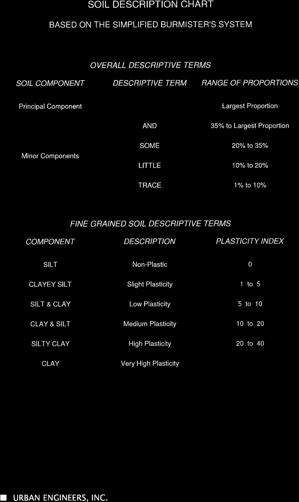
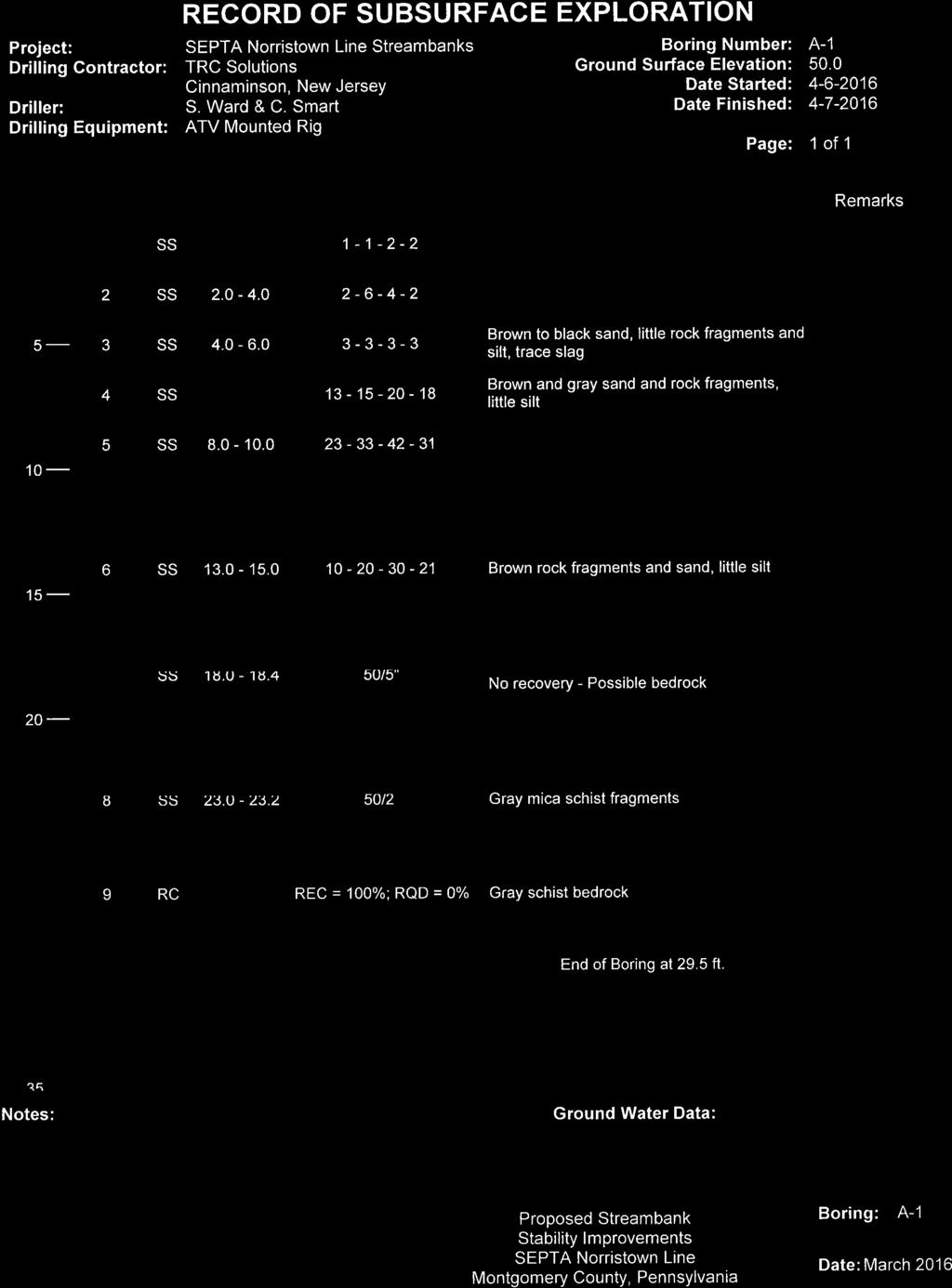
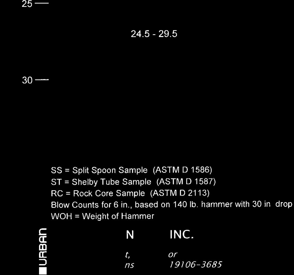
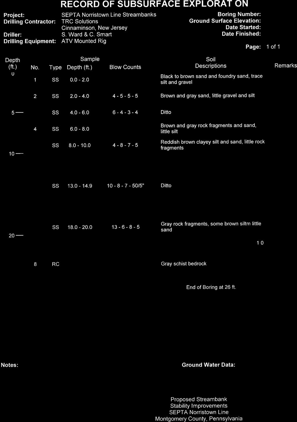
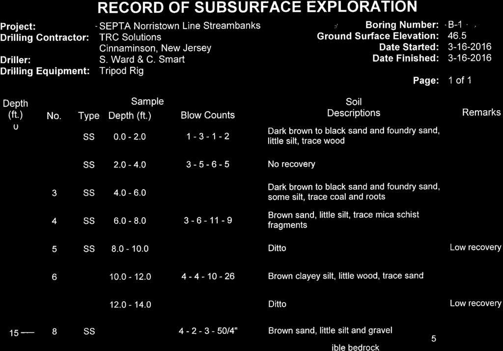
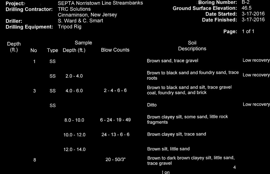
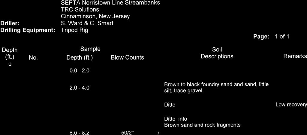
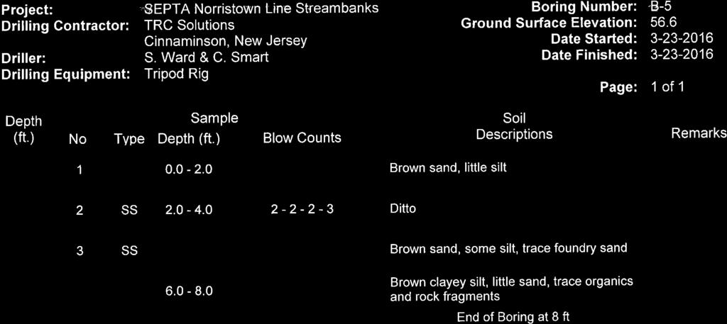
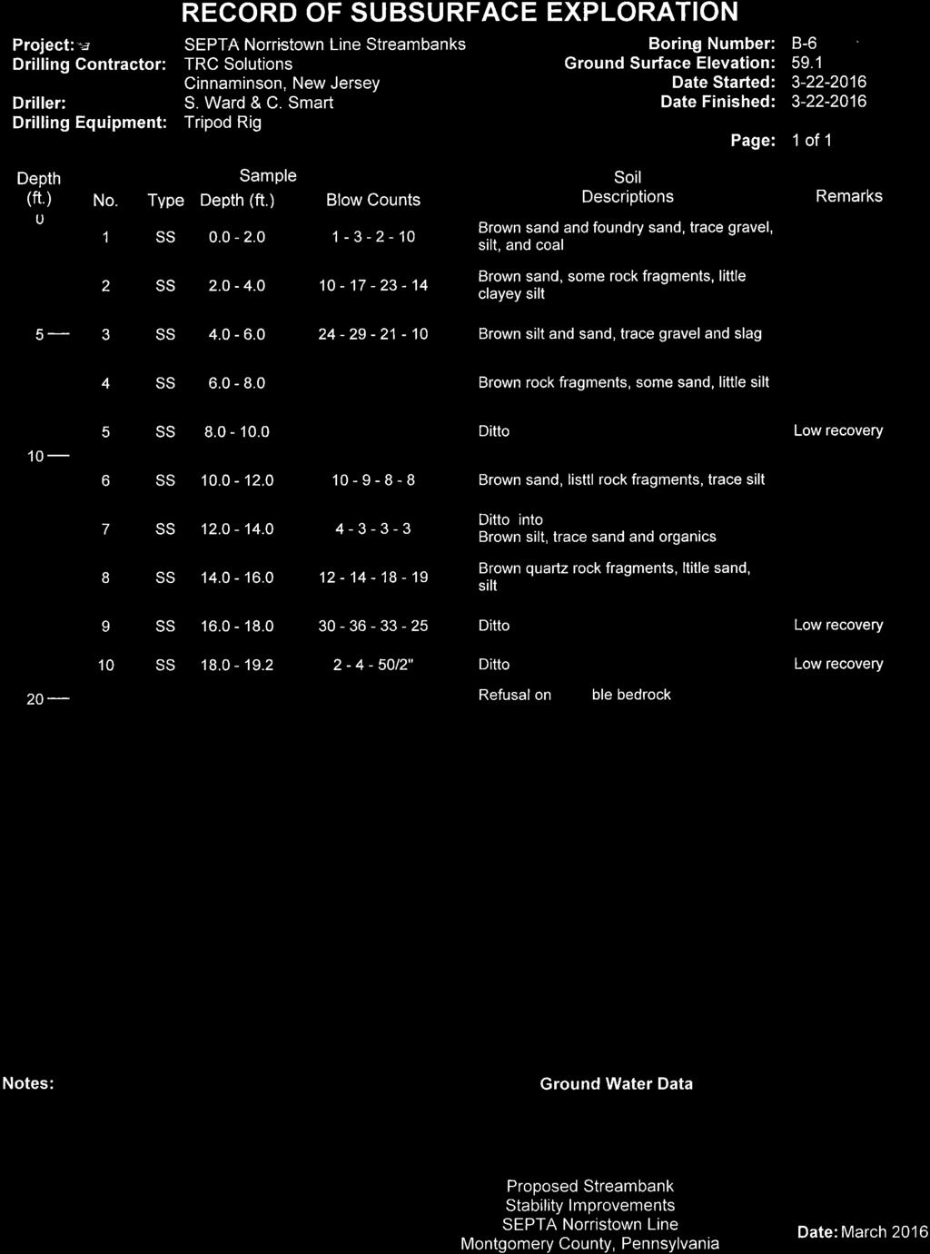
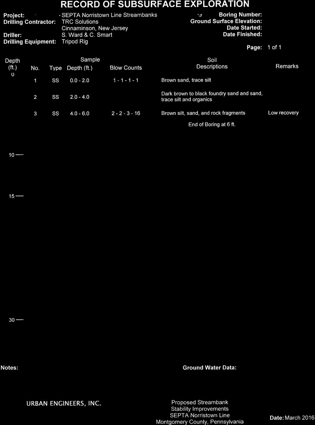
4 Memorandum (Continued) Page 2 of 12 to be removed. The existing stone walls present near the shoreline may conflict with the proposed retaining walls and may need to be removed to construct the new walls. SUBSURFACE EXPLORATIONS Two sets of subsurface explorations have been conducted at the sites as summarized below. All boring logs and associated boring location plans are presented in Appendix B Borings Under the coordination of Urban Engineers Inc., a total of 9 borings were performed by TRC Solutions, Cinnaminson, New Jersey in March and April of Test borings A-1, B-1, and B-2 were performed in the area of Site 1; borings B-3 and B-4 were drilled in the area of Site 2; and Borings A-2, B-5, B-6, and B-7 were advanced in the area of Site 3. An ATV-mounted, diesel powered drilling rig was used to perform two borings (A-1 and A-2) while the remaining borings were performed with a tripod-mounted, motorized cathead rig. At borings A-1 and A-2, Standard Penetration Tests (SPTs) and split spoon sampling was performed continuously in the upper 10 feet and at 5-foot intervals thereafter. At borings B1 through B-7, continuous SPT samplings were obtained. Borings were terminated at depths ranging between 6 feet to 29.5 feet. Rock coring was performed at borings A-1 and A-2. At borings B1, B-2 and B-6, the borings were terminated at refusal depths, possibly on the bedrock. Boring operations were inspected by an Urban Engineer inspector. Ground surface elevations were interpolated from a topographic survey performed by Urban Borings Under the coordination of Jacobs, ten borings (B-101 through B-110) were performed in March and April 2017 by TRC Engineers, Inc. of Mt. Laurel, NJ. Borings B-101 through B-104 are in the area of Site 1 while B-105 through B-110 are located in Site 2. The borings were completed by a barge mounted Acker Soil XLS drill rig within the Schuylkill River. Standard Penetration Tests (SPTs) and split spoon soil sampling were generally performed continuously in the overburden soils using a 140-lb automatic hammer. The borings were terminated at depths ranging from 1 to 14.8 feet below mudline. Rock coring was performed at each boring location except at B-110. Jacobs observed the drilling operations and classified the soils in accordance with the Burmister Classification System. Mudline elevations were determined by Malick & Scherer using a bathymetric survey. Additional borings at Site 3 are being planned which may be drilled in the future to supplement the 2016 boring information. LABORATORY TESTING The laboratory test results from the 2016 boring samples are not available. As part of the 2017 subsurface explorations, laboratory tests were performed on representative samples to further characterize the recovered soils and bedrock. The laboratory testing program consisted of grain size distribution and a suite of chemical analyses for soil corrosion potential. In addition, two rock samples were tested for uniaxial strength. The laboratory test results are presented in Appendix C. Jacobs Engineering Group Inc.
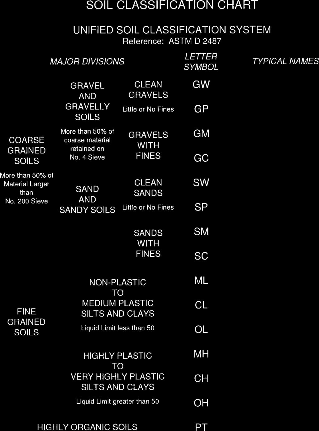
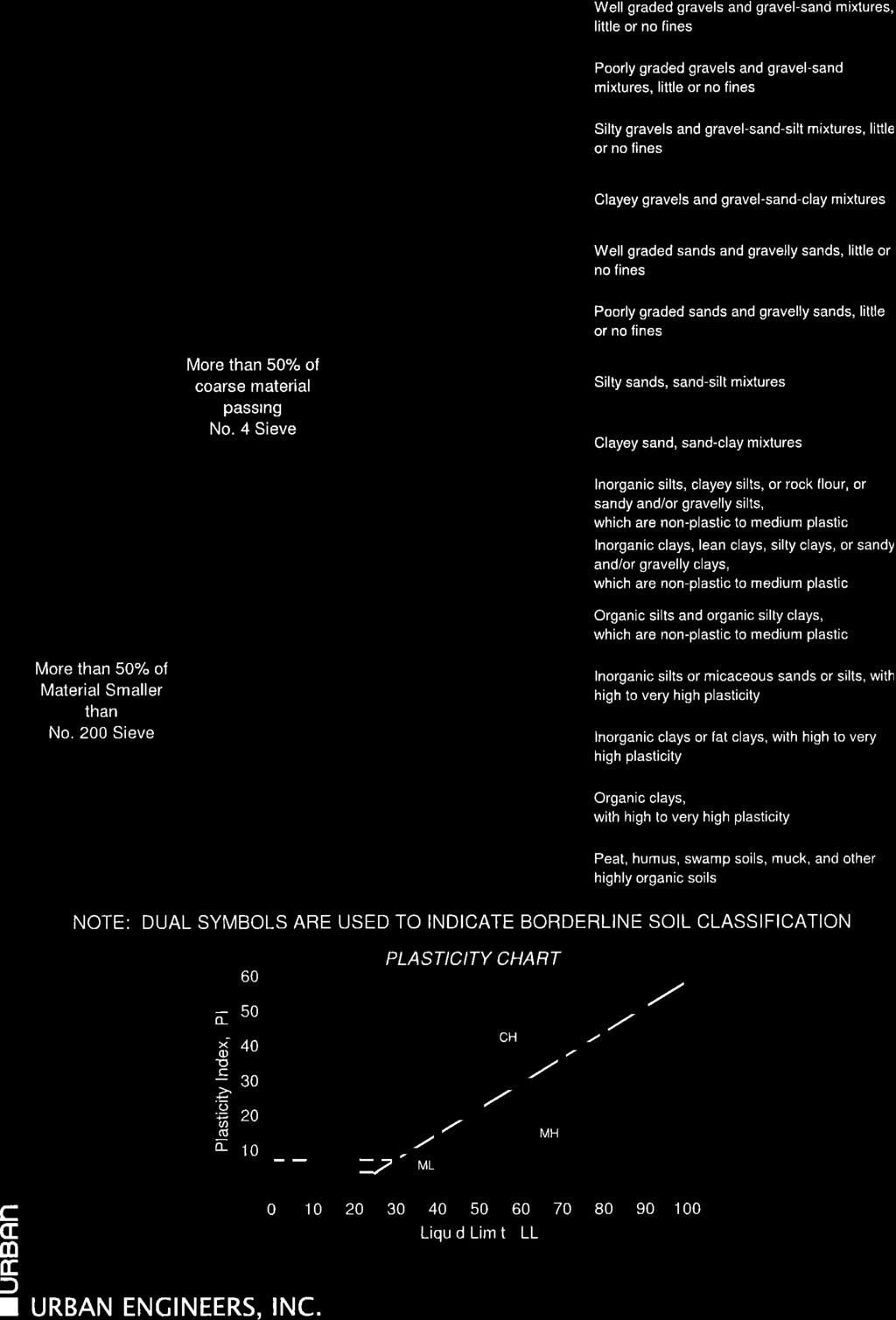
5 Memorandum (Continued) Page 3 of 12 The gradation test results show the tested soil samples are classified as SP-SM, GM or GP-GM in accordance with Unified Soil Classification System (USCS). The rock compressive strength is about 441 and 1,719 tsf at rock cores recovered at borings B-103 and B-109, respectively. The rock core photos are presented in Appendix B. Two composite soil samples were evaluated for corrosivity which included the following tests: Electrical Resistivity ph Sulfate Chloride Sample No. Table 1: Laboratory Corrosion Test Summary Sample Location B-101, S-1; B-103, S-1A; and 1 B-104, S-1A B-105, S-1; B-106, S-1; B-107, 2 S-1A; and B-110, S-1 *: ND = Not Detected Sample Depth (ft) PH Electrical Resistivity (ohm-cm) Chloride (ppm) Sulfate (ppm) 0 ~ ,000 ND* ~ ,000 ND* 170 The composite samples are mixed soil samples at different boring locations at different depths, as shown in Table 1. The Sample Depth in Table 1 refers to the depth below mudline. The corrosivity results are summarized in Table 1. The corrosivity criteria are not defined in AREMA manual. According to 2014 AASHTO LRFD Bridge Design specifications, the following site conditions should generally be considered as indicative of a potentially corrosive environment: Electrical Resistivity less than 2,000 ohm-cm ph less than 5.5 Soils with high organic content Sulfate greater than 500 ppm Chloride greater than 500 ppm Based on the results in Table 1, the corrosion potential at the site appears to be mild. However, due to the high organic content materials encountered at some of the boring locations, we recommend the site be considered as aggressive in corrosion potential. The proper corrosion protection measures are discussed in Section Design Recommendations. SUBSURFACE CONDITIONS The sites are located in the Piedmont physiographic province of Pennsylvania; residual sandy and gravelly soils weathered from underlying bedrocks are typical. Based on the geologic information at the site, the bedrock typically consists of Schist, Gneiss and Dolomite. The following generalized subsurface conditions at the site are inferred from the exploration data collected for the Norristown Line Shoreline Stabilization project, with some interpretations. Jacobs Engineering Group Inc.
6 Memorandum (Continued) Page 4 of 12 The overburden materials are typically granular consisting of sand and gravel with varying amounts of silt and organics. Man-made materials such as brick pieces were encountered at some boring locations which indicate some of the granular materials encountered are previously placed fill. The granular materials are underlain by weathered bedrock often located at relative shallow depths. Sand/Gravel Based on the boring results, the depth of the sand/gravel varies from less than one foot to about 21 feet below grade. SPT N-values suggest the density of this layer varies from very loose to very dense. Most soils appear to be loose to medium dense except very dense materials were encountered at depths of 8 to 10 feet at several boring locations. Bedrock - Bedrock was encountered in all 2017 borings at depths ranging from less than one foot to 8 feet below the mudline. Bedrock was encountered in most 2016 borings at depths ranging from 15 to 21 feet below grade. At Site 1, the recovered bedrock is typically hard, slightly weathered, moderately fractured, fine to medium grained, gray/blue schist. At Site 2, the recovered bedrock is typically slightly weathered, slightly fractured, fine to medium grained, brown and gray gneiss. The rock quality designation (RQD) ranged from 0% to 83%. Rock recovery ranged from to 41% to 100%. It should be noted that severely weathered rock was encountered at A-1, B-101 through B-103, B-106 and B At these locations, the severely weathered rock is about 1 to 7 feet in thickness and the SPT sampling was used to recover the samples. It generally consisted of fine to medium sand with varying amounts of silt and gravel. SPT N-values in the severely weathered rock are typically over 50 which suggest the material is very dense in nature. Based on the boring information, the top of the weathered bedrock is typically located at approximate elevations of 30, 27 and 40 at Site 1, 2 and 3, respectively. The above estimation is considered the average weathered bedrock depth. It is based on the widely spaced boring information and the actual rock surface may vary from location to location. Groundwater - The borings during 2017 subsurface explorations were performed in Schuylkill River. During the time of drilling the water level ranged from approximately elevation 39 to 44 feet, or about 7 to 12 feet above the mudline. The mud line elevation ranged from roughly 27 to 38 feet. The groundwater table was not identified during the 2016 subsurface explorations. It is anticipated that the groundwater table may be located at similar elevations as Schuylkill River. Local or periodic variations of groundwater elevation should be expected as levels may be influenced by season, precipitation, construction activity and other factors. Therefore, groundwater elevations presented herein may not be representative of water levels encountered during construction. DESIGN RECOMMENDATIONS Due to the limited land between the railway and the river, the proposed retaining wall may have to be constructed from a barge or causeway in the river. It is our opinion a sheet pile wall may be suitable as the retaining wall type for this project. Our evaluations in this memorandum consider a sheet pile wall with a tieback anchored in rock as well as shear pins socketed into rock at the sheet pile toe. We have considered a PZ-27 sheet pile wall with a height up to 17 feet. Two alternatives were considered to support the sheet pile wall. The first alternative is to use shear pins installed at the toe of the wall plus a grouted tieback anchor connected to the wall about 3 feet below the top of the wall. The second alternative is to have two tieback anchors spaced at 7 feet vertically between each other; this may eliminate the need for shear pins. The tieback anchor is angled down approximately 15 from horizontal. The tieback anchor is anticipated to be Jacobs Engineering Group Inc.
7 Memorandum (Continued) Page 5 of 12 embedded into the bedrock. In general, the wall design should follow the design recommendations presented in Chapter 8, Part 5 and Part 20 of the AREMA Manual. In addition, the sheet pile retaining wall should be designed to account for the following: Groundwater Table The wall design should consider the seasonal water table fluctuation. The water in the river provides stabilization pressures on the wall. Therefore, the wall design should consider the water at a low level on the river side in the event that downstream dams release water and the river level drops. In addition, we recommend considering a differential water pressure of 3 feet acting on the railroad side of the wall to account for possible unequal water tables across the wall Scour Depth The wall design should consider the scour depth provided in the H&H analysis. Unless future scour analysis indicates otherwise, the design should consider the scour depth at the weathered rock surface. As a result, any developed passive soil resistance above the rock should be ignored. Steel Corrosion The corrosivity test results indicate the soils are corrosive to all structural members. Consequently, protective coatings should be applied to the sheet pile surfaces prior to installations. Protective coatings should be resistant to abrasion and have a proven service record in similar corrosive environment as identified here. If SEPTA or AREMA does not have specific guidance on the protection coating for sheet piles, we recommend using coal tar epoxy. In addition, we recommend to oversize the steel section such that the available section after corrosion meets structural requirements. If SEPTA or AREMA does not have specific guidance on the estimation of sacrificial steel loss, we recommend the sheet pile design consider inches per year of steel thickness loss (per each side of the steel). We recommend a permanent steel casing be used for the purpose of shear pin installations. At a minimum, corrosion protection measures should be applied to the steel casing in accordance with Chapter 8, Part of the AREMA Manual. We further recommend considering a sacrificial steel loss rate of inches per year of steel thickness loss on the outside of the casing. Proper corrosion protection measures should be applied to the tieback anchor system and the shear pin steel bar as required in Chapter 8, Part of the AREMA Manual. The corrosion protection should be consistent with the level of protection for the anchors and the design life of the structure. The overhead catenary wires may increase the corrosion potential due to stray currents. It is recommended the tieback be electrically isolated from the ground. We recommend the corrosion protection to follow Chapter 15, Section of SEPTA s Structural Design Criteria Guidelines. In addition, a steel anchorage cover is recommended to protect the anchor head and exposed steel from corrosion and physical damage. The anchor cover should be filled with grout; special care must be taken to ensure that the cover is completely filled with grout. A trumpet is also recommended to protect the back of the bearing plate and the steel in the transition from the anchorage to the unbonded length. The trumpet should be attached to the bearing plate to provide a water tight seal. This seal is usually made by welding the trumpet to the bearing plate. The trumpet should be long enough to overlap the unbonded length corrosion protection by at least 4 inches and should be completely filled with grout. Jacobs Engineering Group Inc.
8 Memorandum (Continued) Page 6 of 12 Earth Pressure Based on the boring information on the existing sand and gravel, the following soil parameters may be used for the lateral earth pressure computation for the existing soils at the site: Saturated Unit Weight 135 pcf Moist Unit Weight 130 pcf Effective Unit Weight 68 pcf Internal Friction Angle 29 Some fill materials may need to be placed behind the wall to raise the existing grade. We recommend the backfill materials be free-draining Type 1 Backfill in accordance with Tables and of the AREMA Manual. The following soil properties may be used for the lateral earth pressure computation, assuming compacted Type 1 Backfill: Saturated Unit Weight 135 pcf Moist Unit Weight 130 pcf Effective Unit Weight 68 pcf Internal Friction Angle 32 No cohesion should be considered for the above granular materials. We recommend not considering the friction between the steel sheeting and the soil when designing the wall. It should be noted that the ground surface is not level behind the wall on the railway side; the earth pressure should properly take into account the sloped surface. In addition, the existing tracks are located at a relatively short distance from the wall which needs to be considered in the earth pressure computations. We recommend Cooper E-80 be considered as the live load surcharge on the tracks. If construction vehicles or equipment may be present behind the wall during construction or for future wall maintenance and inspections, the proper live load surcharge should also be included in the wall stability analysis; a minimum 400 psf surcharge is recommended for equipment loading. The estimation of earth pressure and surcharge from the tracks should follow Chapter 8, Part 20.3 of the AREMA Manual. We recommend a safety factor of 2 be applied to the calculated earth pressure for wall stability analysis. This safety factor should be applied by doubling the earth pressure for the wall stability analysis. Shear Pin The shear pin steel bar should be extended a minimum of 5 feet above the rock surface with at least 5 feet bonded length in rock, for a minimum bar length of 11 feet; the steel casing should extend from a minimum of one foot into rock to a minimum of 2.5 feet above the existing river level to allow for grouting of the shear pin bar and casing. The drilled hole in the rock should be sized to provide minimum 1.5-inch grout cover all around the shear pin. We recommend the grout have at least 4,000 psi compressive strength. The design should consider a possible gap between the toe of sheet pile and the rock surface. It is recommended a 4 inch gap (vertical distance) be considered in the shear pin design. The shear pin will be primarily subject to the lateral force transferred from the toe of the sheet pile. The wall designer may consider performing a lateral pile analysis (LPile or similar) to determine the possible deflection, shear and moment distributions along the shear pin length. The spacing of the shear pins along the wall alignment should not exceed 2.3 feet. If needed, extra support capacity at the toe can be provided by having more than one shear pin per sheet pile Jacobs Engineering Group Inc.
9 Memorandum (Continued) Page 7 of 12 pair. The sheet piles likely will not be able to penetrate the severely weathered rock. Therefore, the designer should also consider the shear pin to be embedded into the severely weathered rock instead of sound bedrock. The shear pin should be properly sized to structurally resist the loads in accordance with Chapter 8, Part 20.5 of the AREMA Manual. We recommend the following properties be used to model the severally weathered rock: Moist Unit Weight 145 pcf Effective Unit Weight 82 pcf Uniaxial Strength 200 psi Modulus of Rock Mass 16 ksi RQD 0 Strain Factor k rm (Weak Rock) Local yielding near the toe may occur at the bottom corners of the sheet pile and along the connection between the wall and the shear pin or the casing. The designer should consider this localized yielding of the sheet pile at the locations connecting with shear pins. It may be beneficial to reinforce the toe with welded steel plates as discussed in the next section of the memorandum. The tieback anchor will result in downward force on the sheet piles. If the shear pin is bonded with the sheet pile toe, the shear pin may be subject to compression in addition to the lateral force discussed before. For this case, considering the possible gap between the sheet pile toe and the bedrock surface, it is recommended the shear pin be designed for the full compression load resulted from the tieback anchor (i.e. assuming sheet pile is not in contact with the rock) as well as any associated lateral forces and moments. We recommend an ultimate unit bond friction strength of 15 ksf at the grout-rock interface for gravity grouting method. To take advantage of the orientation of the sheet pile interlocks, we recommend placing the shear pins on the side of the interlock such that the resisting force from the shear pin and the active earth pressure acting on the wall press both sides of the interlock towards each other. Otherwise, possible declutching of the interlock may occur. This is discussed in A verification method for toe support of sheet pile walls driven to bedrock by Kort and Karlsrud of Norwegian Geotechnical Institute in 2008, which is illustrated in the figure below. Case 1: preferred location; Case 2: location conductive to declutching of the interlocks (Kort and Karlsrud, 2008) Jacobs Engineering Group Inc.
10 Memorandum (Continued) Page 8 of 12 Tieback Anchor The tieback anchor system should be designed in general accordance with Chapter 8, Part 20.5 of the AREMA Manual. The rock anchor should have a minimum bonded length of 20 feet into bedrock. The drilled hole in the rock should be sized to provide minimum 2.5-inch grout cover around the tendon. The inclination of the tieback is usually between 15 and 30 degrees from the horizontal. The rock anchor should be located at sufficient distance away from the wall. We recommend the minimum distance between the front of the bond zone and the active zone behind the wall of 7 feet. Based on the encountered rock conditions, we recommend the ultimate unit bond strength of 15 ksf at the grout-rock interface for gravity grouting method. We recommend a minimum safety factor of 2 be used for anchor pullout capacity. We recommend the grout to have at least 4,000 psi compressive strength. The minimum horizontal spacing of the anchors should be the larger of three times the diameter of the bonded zone, or 5 feet. The tieback rod should be properly sized to structurally resist the loads in accordance with Chapter 8, Part 20.5 of the AREMA Manual. In addition, the tieback systems need to be located to avoid interference with the existing catenary pole foundations. The tieback system should not be installed within four feet of the sides of the foundation. The tieback system should be properly protected from corrosion as discussed in Steel Corrosion section of the report. Seismic Site Class For seismic design considerations, an appropriate seismic site class should be evaluated in accordance with Chapter 9, Part of the AREMA manual. Based on the soil and rock conditions encountered at the site, a site class D is recommended for the seismic design for all three walls. Appendix D presents the seismic site class calculations as well as the associated seismic site factors. The estimated horizontal acceleration for the 475-year return period earthquake is less than 10 percent of the gravity acceleration. According to Chapter 9, Section of the AREMA manual, no seismic effect on the proposed retaining wall needs to be considered. CONSTRUCTION CONSIDERATIONS It is anticipated that the sheet piling system will be installed from a barge or causeway on Schuylkill River. If a barge is used, it should be properly anchored to provide a stable working platform to accommodate the heavy construction equipment. The river is dam controlled and there are limited access locations along the river. Also, some portions of the river are very shallow and may not be navigable with a boat or barge. Existing facilities to remain during construction include railway tracks and utilities. These facilities should be protected from damage during construction of the new retaining walls. It is recommended that vertical and horizontal movement monitoring points be established on the existing railway tracks and ground surfaces at the utility locations prior to the start of construction to allow monitoring of these structures for potential movement during construction. If any adjacent structures or utilities are deemed by the Engineer to be sensitive to vibration induced damage, vibration monitoring shall be performed during construction. The specifications should require the contractor to submit a plan describing precautions to be taken to minimize potential movement and vibration levels at the adjacent railroad tracks and utilities prior to construction. The specifications should also define the tolerable values of movements and/or vibration levels associated with Jacobs Engineering Group Inc.
11 Memorandum (Continued) Page 9 of 12 each structure or utility. If some of the utilities need to be relocated, it should be coordinated with SEPTA and/or the utility owners. Sheet Pile Installation Ideally the sheet pile should be driven such that it will be in full contact with the sound bedrock. However, at places where severely weathered bedrock is present, the sheet pile will likely stop at the severely weathered rock surface. As described in the Subsurface Conditions section, very dense sand and gravel may be encountered at 8 to 10 feet depths at some locations. Hammer driving or a combination of vibration driving and hammer driving will be required to account for the different soil conditions at different depths. Care shall be taken during driving to keep from causing deformations of the top of the piles, splitting of section, or breaking of the interlock between sections. Care shall also be taken during driving to prevent and correct any tendency of steel sheet piles to twist or get out of plumb. It is anticipated that hammer driving will be used for final driving depths near the rock surface. The practical refusal may be defined as more than 12 blows per inch of penetration with an approved hammer system. The contractor should submit the proposed installation method and associated equipment. The above practical refusal may need to be revised based on the specific driving system proposed by the contractor. The contractor should ensure that the sheet piles will not be damaged while using hammer driving, particularly when driving near the bedrock depth. This may require the contractor to select a proper driving system based on the sheet pile type and the existing soil/rock conditions. It is anticipated that the combination of hammer driving and vibration driving will be sufficient for the onsite soils and that no jetting or predrilling through the dense sand and gravel layer is required. A complete driving record is to be kept during the execution of the piling work. The length of the sheet pile section, the elevation of the top of the sheet pile, and the elevation of the sheet pile toe on reaching the rock and, if it is possible to drive the sheet pile toe into the rock, the final elevation of the toe in the rock are to be recorded for each sheet pile profile driven. When shear pins are used, an accuracy of 1 inch is required for these measurements as the capacity of the slender shear pin sections are very sensitive to the size of the gap between the sheet pile toe and the bedrock. The verification of gap depth is discussed in the next section of this memorandum. Shear Pin Installation The installation of shear pins is typically done either by a pre-attached steel casing prior to sheet pile installation, or by drilling a hole in the rock with a steel casing after the sheet pile installation. Based on the site conditions, we recommend installing the shear pin after the sheet pile wall is installed. A steel casing is required to drill through the overburden soils down to the bedrock. The casing should be in contact with (as close as possible to) the wall in order to provide effective support to the sheet pile toe; the casing shall be permanent. We recommend the casing have at least one foot embedment into the bedrock. We also recommend the top of the casing be restrained from lateral movement at the top by using a steel angle welded to the sheet pile wall located 1.5 feet below the top of the casing. The steel casing should not be welded to the sheet pile wall. The hole should be flushed clean and filled with grout until good quality grout is observed at the top of the casing through a hose fed down to the bottom of the hole before the shear pin is installed. The grout must be placed within one hour after mixing the grout, or within the time recommended by the manufacturer. Grouting should occur within 24 hours after drilling completion. Care must be taken to ensure that the shear pin has been placed fully down to the bottom of the hole and sometimes it may be necessary to push the Jacobs Engineering Group Inc.
12 Memorandum (Continued) Page 10 of 12 shear pin down fully using the drilling equipment; however, if it does not move down easily, the pin should be removed and the hole redrilled It is required that the gap between the sheet pile toe and the bedrock surface be less than 3 inches after sheet pile installation. The elevation of the rock surface at the location of the shear pin can be measured and recorded during the drilling. If a casing attached to the sheet pile is being used for shear pin installation then the actual gap can be measured accurately. The distance between the top of the concrete plug at the base of the casing and the toe of the sheet pile is measured prior to driving. The elevation of the top of the concrete plug in the casing is measured. Thus the elevation of the toe of the wall is known. Using the rock surface elevation measured during the drilling of the shear pin, the gap is calculated. When installing the casing and shear pin after the wall installation, the gap can be estimated by using the results of the drilling information and sheet pile driving record to determine the elevation of the sheet pile toe. Tieback Anchor Installation The drilling equipment, methods and sequence should be suitable for drilling through the soil/rock conditions encountered at the site. The contractor is responsible for using a drilling method to establish a stable hole of adequate dimensions. Special care should be exercised in the selection of drilling methods when excessive loss of ground could endanger the stability of adjacent structures or utilities. This is particularly important for rock anchors located under the railway tracks; a steel casing will be required in such cases. Drilled casings should be cleaned upon completion of drilling. The tieback anchor shall be installed before grouting. Holes open for longer than 2 hours should be re-cleaned prior to insertion of the tieback and grouting. Centralizers shall be securely affixed to tiebacks at maximum 5 to 10 feet intervals and properly sized such that grout may flow freely up the borehole around the tieback. Grouting should be performed as soon as practical after installation of the tieback anchor to minimize the potential for hole caving. Grouting equipment should allow for continuous grouting and completion of grouting of each anchor in less than one hour. Grouting of the tieback should be performed in one stage. Grout should be injected at the lowest point in the drill hole to fill the hole without generating air voids. The grout must be placed within one hour after mixing the grout, or within the time recommended by the manufacture, whichever is less. Grouting of the bonded zone should occur within 24 hours after drilling completion. The grout should flow continuously as the grout tube is withdrawn. The withdrawal rate should be less than the grout placement rate to maintain the grout discharge point below the grout surface in the drill hole. The anchor should be tested for pullout capacity. The load tests typically include both Performance Test and Proof Test. We recommend the load test to follow Chapter 15, Section 4.3 of SEPTA s Structural Design Criteria Guidelines. Earthwork Prior to performing any required grading operations and backfilling, the site should be prepared by removing any topsoil, man-made materials, unsuitable fill materials, frozen, wet, soft or loose soils; and any other deleterious materials. These operations should be performed in a manner consistent with good erosion and sediment control practices. It is anticipated that the earthwork will not affect the existing tracks. Fill will be placed behind the wall. Extreme care should be exercised not to damage the sheet pile wall or any components of its tieback system. All material to be used as fill or backfill should be inspected, tested Jacobs Engineering Group Inc.
13 Memorandum (Continued) Page 11 of 12 and approved by the Engineer. Any imported engineered fill should be classified as Type 1 Backfill in accordance with Tables and of the AREMA Manual. All fill should be placed in lifts not exceeding 10 inches in loose thickness and moisture conditioned to within ±2% of the optimum moisture content. In confined areas, place only 6-inch layers and compact with manually operated, powered vibratory compactor. Engineered fill should be compacted to a minimum of 90% of the maximum dry density obtained in accordance with ASTM Specification D-698, Standard Proctor Method. All areas receiving fill should be graded to facilitate positive drainage. Within 10 feet of the wall, compaction should be performed with manually operated, walk-behind compactors to limit pressures on the wall. All earthwork should be performed in the dry condition. Based on the groundwater levels observed at the time of the subsurface explorations, we anticipate all earthworks will be performed above the groundwater table. LIMITATIONS This memorandum and the recommendations contained herein have been prepared for the exclusive use of Jacobs and SEPTA and their representatives for specific application to the design and construction of the proposed retaining walls for Norristown Line Shoreline Stabilization Project in Montgomery County, PA. This memorandum was prepared in accordance with generally accepted soil and foundation engineering practices. No warranty, expressed or implied, is made. The analysis, design and recommendations submitted in this report are based in part upon the data obtained from subsurface explorations available at the time of this report. Subsurface stratification variations between explorations are anticipated; this could be particularly the case for the bedrock surface. The reported groundwater levels are short-term observations and only represent the water levels at the time of the explorations and as noted on the exploration logs. The nature and extent of variations between these explorations may not become evident until construction. If significant variations then appear, or if there are changes in the nature, design, or location of the proposed structure, it may be necessary to re-evaluate the recommendations of this report. We appreciate the opportunity to be of service to you on this project. Please contact us if you have any questions regarding this report. Very truly yours, Jacobs Engineering Group Lei Wei, Ph.D., P.E. Senior Geotechnical Engineer Paul Murphy, P.E. Geotechnical Group Manager ATTACHMENTS Figure 1 Site Location Plan Appendix A Existing Site Photos Jacobs Engineering Group Inc.

14 Memorandum (Continued) Page 12 of 12 Appendix B Boring Logs and Boring Location Plans Appendix C Laboratory Test Results Appendix D Site Seismic Class O:\INFRASTRUCTURE\GEOTECHNICAL\SEPTA Retg Walls\Report\Design Memo.doc Figure 1. Site location Plan Jacobs Engineering Group Inc.
15 Jacobs Engineering Group Inc APPENDIX A EXISTING SITE PHOTOS


16 Photo 1: General Site Photo Schuylkill River Photo 2: General Site Photo - Barge & Drill Rig Jacobs Engineering Group Inc.


17 Photo 3: Existing Shoreline near B-103 at Site 1 Looking Northeast Photo 4: Existing Shoreline near B-107 at Site 2 Looking Northeast Jacobs Engineering Group Inc.
18 Jacobs Engineering Group Inc. APPENDIX B BORING LOGS AND BORONG LOCATION PLANS
19 Appendix B.1 - Boring Location Plans and Profiles
20
21
22
23
24
25
26
27 Appendix B Boring Logs
28
29
30
31
32

33
34
35
36
37
38
39 Appendix B Boring Logs
40 GrfcText!BORING LOG KEY 5/4/2017 8:50:13 AM ELEV. (ft) DEPTH (ft) SAMPLE DATA N- VALUE SAMPLE NO. DEPTH INTERVAL (ft) BORING LOG KEY PEN/REC (in)/(in) PID (ppm) LAYER NAME SOIL AND ROCK DESCRIPTION COLUMN DESCRIPTIONS ELEV (feet): Elevation in feet as per datum specified on log. DEPTH (feet): Depth in feet below the ground surface or barge. SAMPLE DATA: Type of soil/rock sample and data collected over the depth interval shown. N-VALUE (Uncorrected): Cumulative number of uncorrected blows for the middle two six-inch intervals (blows/foot). SAMPLE NUMBER: Sample identification number DEPTH INTERVAL (feet): Depth interval of the soil or rock sample collected. PID (parts per million): PID reading observed during drilling. LAYER NAME: Inferred name and delineation of subsurface strata. 10 SOIL AND ROCK DESCRIPTION: Description of material encountered Market Street Suite 1000 Philadelphia, Pennsylvania PEN/REC (inch/inch): Soil or rock sample penetration / amount of soil or rock recovered. NOTES 11 NOTES: Comments/observations regarding drilling/sampling made by driller or field personnel. 11 COMPONENT MAJOR Minor GRANULAR SOILS DENSITY SPT N-VALUE Very Loose Loose Medium Dense Dense Very Dense COMPONENT NAME GRAVEL SAND FINES* Gravel Sand Fines* DENSITY PROPORTIONAL TERM < > 50 NAME n/a and some little trace BURMISTER SOIL CLASSIFICATION (INORGANIC) PERCENT BY WEIGHT Non-Plastic Slight Low Medium High Very High and some trace > > 40 GRADATION DESIGNATIONS fine medium fine to medium medium to coarse fine to coarse PLASTICITY PLASTICITY INDEX FINES* PERCENT BY WEIGHT < 10 SILT Clayey SILT SILT & CLAY CLAY & SILT Silty CLAY CLAY PROPORTIONS OF GRANULAR COMPONENT BURMISTER SOIL CLASSIFICATION (ORGANIC) MASSDOT VISUAL IDENTIFICATION OF SOILS PROPORTIONAL TERM n/a < 10% coarse & medium < 10% coarse & fine Boulders Cobbles Gravel Sand Silt < 10% coarse < 10% fine all > 10% THREAD DIAMETER None 1/4" (6mm) 1/8" (3mm) 1/16" (1.5mm) 1/32" (0.75mm) 1/64" (0.4mm) Very Soft Soft Medium Stiff Very Stiff Hard < > 30 PARTICLE SIZE DEFINITIONS FRACTION SIEVE NO. n/a n/a coarse medium fine coarse fine n/a SOIL Gravel Sand Silt PARTICLE SIZE DEFINITIONS FRACTION SIEVE NO. SIEVE SIZE coarse fine coarse medium fine n/a FINE SOILS SPT N-VALUE Fibrous PEAT - Light weight, spongy, mostly visible organic matter, water squeezes readily from sample. Typically near top of deposit. Fine Grained PEAT - Light weight, spongy, little visible organic matter, water squeezes readily from sample. Typically below fibrous PEAT. Organic SILT - Typically gray to dark gray, often has strong H2S odor. Typically contains shells or shell fragment. Light weight. Usually found near coastal regions. May contain wide range of sand fractions. MAJOR Minor Very Loose Loose Medium Dense Dense Very Dense GRAVEL SAND FINES Gravel Sand Fines GRANULAR SOILS SPT N-VALUE < > 50 > 50 SOIL CONSISTENCY Very Soft Soft Medium Stiff Stiff Very Stiff Hard CONSISTENCY FINE SOILS > 12 in 12 in to 3 in 3 to 1 in 1 in to 3/8 in 3/8 in to No.10 No.10 to No.40 No.40 to No.200 < No in to 3/4 in 3/4 in to No.4 No.4 to No.10 No.10 to No.40 No.40 to No.200 < No.200 SPT N-VALUE < > 30 75mm - 19mm 19mm mm 4.75mm - 2.0mm 2.0mm -.43mm 0.43mm mm < 0.075mm UC STRENGTH < 0.25 tsf tsf tsf tsf tsf > 4.0 tsf SIEVE SIZE > 305mm 305mm - 75mm 75mm - 25mm 25mm - 9.5mm 9.5mm - 2.0mm 2.0mm mm 0.425mm mm < 0.075mm GRAPHIC SYMBOLS ABBREVIATIONS Split-Spoon Sample (SS) and Blow Counts per 6" REC (in) Rock Core (RC) and RQD (%) REC (%) Undisturbed (U) Shelby Tube (P) Piston SS = Split Spoon Sampler U = Undisturbed Sample (Shelby Tube) P = Piston Sample PID = Photoionization Detector ppm = Part Per Million REC = Recovery WOR = Weight of Rods RQD = Rock Quality Designation Auger Sample (AS) Jar Sample (JS) Bag Sample (B) WOH = Weight of Hammer SPT = Stadard Penetration Test (ASTM D2487) PP = Pocket Penetrometer PI = Plasticity Index Water Level UC STRENGTH = Unconfined Compressive Strength
41 INSPECTOR ELEV. (ft) METHOD OF DRILLING Wash Boring w/ 4" Casing NX Rock Core Terminated DEPTH (ft) 5 10 G. Shay SAMPLE DATA WOH WOH WOH WOH /3" RQD=65 N- VALUE /9" SAMPLE NO. S1 S2 S3 S4 C1 PROJECT LOCATION Schuylkill River / Site 1 BORING OWNER SEPTA NO. B-101 JOB NUMBER E3X41215 SHEET 1 OF 1 CONTRACTOR TRC Engineers Inc. DRILLER J. Dotzler ELEVATION 37.5 GROUNDWATER READINGS DRILL RIG Acker Soil XLS DATUM NAVD88 DATE/TIME DEPTH(ft) REMARKS SPT HAMMER 140 lb Auto GRID N / 9:00 AM See Note 1 COORD E DATE START 3/23/17 DATE END 3/23/17 DEPTH INTERVAL (ft) PEN/REC (in)/(in) 24/6 24/8 24/8 15/10 60/44 LOG OF TEST BORING Norristown Line Shoreline Stabilization Improvements PID (ppm) LAYER NAME SAND BEDROCK SOIL AND ROCK DESCRIPTION S1: Wet, very loose, dark brown, fine SAND, some Organic Silt, some(-) Fibrous Peat. S2: Wet, loose, dark brown, fine to medium SAND, some fine to coarse Gravel, trace Silt. (USCS: SP-SM) S3: Wet, medium dense, dark brown, fine SAND and Silt, little fine Gravel, trace wood fibers. S4A (Top 4"): Wet, dark brown, fine to medium SAND, little fine to coarse Gravel, trace Silt. (USCS: SP-SM) S4B (Bottom 6"): Wet, brown, fine to medium SAND, little Silt, trace Gravel (severely weathered rock). C1: Hard, very slightly weathered, slightly fractured, fine to medium grained, blue/gray, SCHIST (bottom 6" extremely fractured and severely weathered). Coring Times (min/ft): NOTES Bottom of Borehole at 12.5 feet Page 1: 0-35 feet. Each subsequent page displays 40 feet. 1. Approximately 6.5 feet of water above mudline. 2. Mudline elevations determined by bathymetric survey. 3. 4" casing hit refusal at approximately 6.3 feet. NOTES
42 ELEV. (ft) G. Shay METHOD OF DRILLING Wash Boring w/ 4" Casing NX Rock Core Terminated INSPECTOR DEPTH (ft) 5 10 SAMPLE DATA WOR WOH /1" RQD=0 RQD=29 N- VALUE 1 100/1" SAMPLE NO. S1 S2 C1 C2 PROJECT LOCATION Schuylkill River / Site 1 BORING OWNER SEPTA NO. B-102 JOB NUMBER E3X41215 SHEET 1 OF 1 CONTRACTOR TRC Engineers Inc. DRILLER J. Dotzler ELEVATION 33.2 GROUNDWATER READINGS DRILL RIG Acker Soil XLS DATUM NAVD88 DATE/TIME DEPTH(ft) REMARKS SPT HAMMER 140 lb Auto GRID N / 9:00 AM See Note 1 COORD E DATE START 3/22/17 DATE END 3/22/17 DEPTH INTERVAL (ft) PEN/REC (in)/(in) 24/12 1/0 17/15 42/29 LOG OF TEST BORING Norristown Line Shoreline Stabilization Improvements PID (ppm) LAYER NAME 1.5 W/R 4.6 BEDROCK 9.5 S1A (Top 6"): Wet, dark brown, Fibrous PEAT, little fine Sand, little Silt. S1B (Bottom 6"): Wet, brown, fine to coarse SAND, little Silt (severely weathered rock). S2: No recovery. SOIL AND ROCK DESCRIPTION C1: Hard, moderately weathered, extremely fractured, fine grained, gray SCHIST with very closely to closely spaced, horizontal to sub-horizontal fractures. Coring Times (min/ft): 2-2/5" C2: Hard, slightly to moderately weathered, moderately to extremely fractured, fine grained, gray SCHIST with very closely to closely spaced, sub-horizontal fractures. Coring Times (min/ft): /6" Bottom of Borehole at 9.5 feet. NOTES Page 1: 0-35 feet. Each subsequent page displays 40 feet. 1. Approximately 9 feet of water above mudline. 2. Mudline elevations determined by bathymetric survey. 3. Core barrel jammed at approximately 6 feet. NOTES
43 INSPECTOR ELEV. (ft) METHOD OF DRILLING Wash Boring w/ 4" Casing NX Rock Core Terminated DEPTH (ft) 5 10 G. Shay SAMPLE DATA WOH RQD=0 RQD=44 N- VALUE SAMPLE NO. S1 S2 S3 S4 C1 C2 PROJECT LOCATION Schuylkill River / Site 1 BORING OWNER SEPTA NO. B-103 JOB NUMBER E3X41215 SHEET 1 OF 1 CONTRACTOR TRC Engineers Inc. DRILLER J. Dotzler ELEVATION 31.3 GROUNDWATER READINGS DRILL RIG Acker Soil XLS DATUM NAVD88 DATE/TIME DEPTH(ft) REMARKS SPT HAMMER 140 lb Auto GRID N / 12:00 PM See Note 1 COORD E DATE START 3/22/17 DATE END 3/22/17 DEPTH INTERVAL (ft) PEN/REC (in)/(in) 24/15 24/13 24/18 24/18 22/9 60/60 LOG OF TEST BORING Norristown Line Shoreline Stabilization Improvements PID (ppm) LAYER NAME SAND 2 W/R 8 BEDROCK SOIL AND ROCK DESCRIPTION S1A (Top 5"): Wet, dark brown, fine to medium SAND and Silt, some wood fibers. S1B (Bottom 10"): Wet, brown, fine to coarse GRAVEL and fine to coarse Sand, little(-) Silt. (USCS: GM) S2: Wet, dense, brown, fine to medium SAND (severely weathered rock). S3: Wet, very dense, brown, fine to medium SAND (severely weathered rock). S4: Wet, very dense, brown, fine to medium SAND (severely weathered rock). C1: Hard, slightly to moderately weathered, extremely fractured, fine grained, blue/gray, SCHIST with closely spaced, sub-horizontal fractures. Coring Times (min/ft): 2-1/10" C2: Hard, slightly weathered, moderately fractured, fine grained, blue/gray SCHIST with closely spaced, horizontal to sub-horizontal fractures. Coring Times (min/ft): NOTES Bottom of Borehole at 14.8 feet Page 1: 0-35 feet. Each subsequent page displays 40 feet. 1. Approximately 9 feet of water above mudline. 2. Mudline elevations determined by bathymetric survey. 3. Core barrel jammed at approximately 9.8 feet. NOTES
44 ELEV. (ft) G. Shay METHOD OF DRILLING Wash Boring w/ 4" Casing NX Rock Core Terminated INSPECTOR DEPTH (ft) 5 SAMPLE DATA WOR WOR 8 100/3" RQD=0 RQD=0 C1 C2 PROJECT LOCATION Schuylkill River / Site 1 BORING OWNER SEPTA NO. B-104 JOB NUMBER E3X41215 SHEET 1 OF 1 CONTRACTOR TRC Engineers Inc. DRILLER J. Dotzler ELEVATION 31.9 GROUNDWATER READINGS DRILL RIG Acker Soil XLS DATUM NAVD88 DATE/TIME DEPTH(ft) REMARKS SPT HAMMER 140 lb Auto GRID N / 9:00 AM See Note 1 COORD E DATE START 3/21/17 DATE END 3/21/17 N- SAMPLE DEPTH PEN/REC PID VALUE NO. INTERVAL (in)/(in) (ppm) (ft) 8 S / /32 24/24 LOG OF TEST BORING Norristown Line Shoreline Stabilization Improvements LAYER NAME 2 BEDROCK 7 SOIL AND ROCK DESCRIPTION S1A (Top 4"): Wet, dark brown, fine to medium SAND, some Silt, little fine Gravel, little Fibrous Peat. S1B (Bottom 3"): Wet, brown/yellow, fine to coarse GRAVEL (bedrock fragments). C1: Hard to medium, slightly weathered, extremely fractured, fine grained, dark gray/ blue SCHIST with closely spaced, moderately dipping fractures. Coring Times (min/ft): C2: Hard, slightly weathered, extremely fractured, fine grained, dark gray/ blue SCHIST with closely spaced, moderately dipping fractures. Coring Times (min/ft): 4-4 Bottom of Borehole at 7 feet. NOTES Page 1: 0-35 feet. Each subsequent page displays 40 feet. 1. Approximately 8 feet of water above mudline. 2. Mudline elevations determined by bathymetric survey. 3. Core barrel jammed at approximately 5 feet. NOTES
45 ELEV. (ft) G. Shay METHOD OF DRILLING Wash Boring w/ 4" Casing NX Rock Core Terminated INSPECTOR 25 DEPTH (ft) 5 SAMPLE DATA 6 100/1" RQD=53 PROJECT LOCATION Schuylkill River / Site 2 BORING OWNER SEPTA NO. B-105 JOB NUMBER E3X41215 SHEET 1 OF 1 CONTRACTOR TRC Engineers Inc. DRILLER J. Dotzler ELEVATION 29.8 GROUNDWATER READINGS DRILL RIG Acker Soil XLS DATUM NAVD88 DATE/TIME DEPTH(ft) REMARKS SPT HAMMER 140 lb Auto GRID N / 9:00 AM See Note 1 COORD E DATE START 3/29/17 DATE END 3/29/17 N- SAMPLE DEPTH PEN/REC VALUE NO. INTERVAL (in)/(in) (ft) 100/1" S1 C /4 60/50 LOG OF TEST BORING Norristown Line Shoreline Stabilization Improvements PID (ppm) LAYER NAME 0.6 BEDROCK 5.6 SOIL AND ROCK DESCRIPTION S1: Wet, very dense, brown, fine to coarse SAND, trace Gravel, trace Silt, trace shells (rock fragments in spoon tip). C1 (0-19"): Hard, very slightly weathered, moderately fractured, fine to coarse grained, gray/ white GNEISS with closely spaced, horizontal to sub-horizontal fractures. C1 (19" - 34"): Hard, very slightly weathered, moderately fractured, dark gray, SCHIST. C1 (34" - 50"): Hard, very slightly weathered, moderately fractured, fine to coarse grained, gray/ white GNEISS with closely spaced, horizontal to sub-horizontal fractures. Coring Times (min/ft): Bottom of Borehole at 5.6 feet. NOTES Page 1: 0-35 feet. Each subsequent page displays 40 feet. 1. Approximately 10 feet of water above mudline. 2. Mudline elevations determined by bathymetric survey. NOTES
46 ELEV. (ft) G. Shay METHOD OF DRILLING Wash Boring w/ 4" Casing NX Rock Core Terminated INSPECTOR DEPTH (ft) 5 10 SAMPLE DATA /4" RQD=0 RQD=83 N- VALUE /10" SAMPLE NO. S1 S2 C1 C2 PROJECT LOCATION Schuylkill River / Site 2 BORING OWNER SEPTA NO. B-106 JOB NUMBER E3X41215 SHEET 1 OF 1 CONTRACTOR TRC Engineers Inc. DRILLER J. Dotzler ELEVATION 29.1 GROUNDWATER READINGS DRILL RIG Acker Soil XLS DATUM NAVD88 DATE/TIME DEPTH(ft) REMARKS SPT HAMMER 140 lb Auto GRID N / 9:00 AM See Note 1 COORD E DATE START 3/27/17 DATE END 3/27/17 DEPTH INTERVAL (ft) PEN/REC (in)/(in) 24/12 16/12 24/24 36/30 LOG OF TEST BORING Norristown Line Shoreline Stabilization Improvements PID (ppm) LAYER NAME 0.7 W/R 4.5 BEDROCK 9.5 SOIL AND ROCK DESCRIPTION S1A (Top 8"): Wet, dark brown, fine to coarse SAND and fine to coarse Gravel, little Silt. S1B (Bottom 4"): Wet, brown, fine to coarse GRAVEL and fine to coarse Sand, little Silt (severely weathered rock). S2: Wet, very dense, brown, fine to coarse GRAVEL and fine to coarse Sand, some Silt (severely weathered rock). C1: Hard, slightly weathered, extremely to moderately fractured, fine to coarse grained, brown/gray GNEISS with very closely spaced, sub-horizontal fractures. Coring Times (min/ft): 3-3 C2: Hard, slightly weathered, moderately fractured, fine to coarse grained, brown/gray GNEISS with very closely spaced, sub-horizontal fractures. Coring Times (min/ft): Bottom of Borehole at 9.5 feet. NOTES Page 1: 0-35 feet. Each subsequent page displays 40 feet. 1. Approximately 10 feet of water above mudline. 2. Mudline elevations determined by bathymetric survey. NOTES
47 ELEV. (ft) G. Shay METHOD OF DRILLING Wash Boring w/ 4" Casing NX Rock Core Terminated INSPECTOR 25 DEPTH (ft) 5 SAMPLE DATA /3" RQD=47 RQD=69 C1 C2 PROJECT LOCATION Schuylkill River / Site 2 BORING OWNER SEPTA NO. B-107 JOB NUMBER E3X41215 SHEET 1 OF 1 CONTRACTOR TRC Engineers Inc. DRILLER J. Dotzler ELEVATION 29.1 GROUNDWATER READINGS DRILL RIG Acker Soil XLS DATUM NAVD88 DATE/TIME DEPTH(ft) REMARKS SPT HAMMER 140 lb Auto GRID N / 12:00 PM See Note 1 COORD E DATE START 3/27/17 DATE END 3/27/17 N- SAMPLE DEPTH PEN/REC VALUE NO. INTERVAL (in)/(in) (ft) 100/3" S / /36 24/24 LOG OF TEST BORING Norristown Line Shoreline Stabilization Improvements PID (ppm) LAYER NAME BEDROCK 7 SOIL AND ROCK DESCRIPTION S1A (Top 3"): Wet, dark brown, fine to coarse SAND, little Silt, little fine Gravel, trace Shells. S1B (Bottom 5"): Wet, brown, fine to coarse GRAVEL, little Silt, little Sand (severely weathered rock). C1: Hard, slightly weathered, extremely to moderately fractured, fine to coarse grained, brown/gray GNEISS with close to very closely spaced sub-horizontal fractures. Coring Times (min/ft): C2: Hard, slightly weathered, moderately fractured, fine to medium grained, gray/green SCHIST with closely spaced, sub-horizontal fractures. Coring Times (min/ft): Bottom of Borehole at 7 feet. NOTES Page 1: 0-35 feet. Each subsequent page displays 40 feet. 1. Approximately 11 feet of water above mudline. 2. Mudline elevations determined by bathymetric survey. 3. Rig chatter as the rollerbit advanced from 0.8 to 2 feet, weathered rock. NOTES
48 ELEV. (ft) G. Shay METHOD OF DRILLING Wash Boring w/ 4" Casing NX Rock Core Terminated INSPECTOR 25 DEPTH (ft) SAMPLE DATA 100/5" RQD=41 PROJECT LOCATION Schuylkill River / Site 2 BORING OWNER SEPTA NO. B-108 JOB NUMBER E3X41215 SHEET 1 OF 1 CONTRACTOR TRC Engineers Inc. DRILLER J. Dotzler ELEVATION 27.2 GROUNDWATER READINGS DRILL RIG Acker Soil XLS DATUM NAVD88 DATE/TIME DEPTH(ft) REMARKS SPT HAMMER 140 lb Auto GRID N / 9:00 AM See Note 1 COORD E DATE START 3/24/17 DATE END 3/24/17 N- SAMPLE DEPTH PEN/REC VALUE NO. INTERVAL (in)/(in) (ft) 100/5" S1 C /4 48/39 LOG OF TEST BORING Norristown Line Shoreline Stabilization Improvements PID (ppm) LAYER NAME 0.4 BEDROCK SOIL AND ROCK DESCRIPTION S1: Wet, very dense, dark brown/ brown, fine to coarse GRAVEL, some fine to coarse Sand, trace Silt (USCS: GP-GM). C1: Hard to moderately hard, slightly to moderately weathered, extremely to moderately fractured, fine to medium grained, blue/gray GNEISS with close to very closely spaced, sub-horizontal fractures. Coring Times (min/ft): NOTES RQD=33 C / C2: Hard, slightly weathered, moderately fractured, fine to medium grained, blue/gray GNEISS with close to very closely spaced, sub-horizontal fractures. Coring Times (min/ft): 2 Bottom of Borehole at 5.4 feet Page 1: 0-35 feet. Each subsequent page displays 40 feet. 1. Approximately 12 feet of water above mudline. 2. Mudline elevations determined by bathymetric survey. NOTES
49 ELEV. (ft) G. Shay METHOD OF DRILLING Wash Boring w/ 4" Casing NX Rock Core Terminated INSPECTOR 25 DEPTH (ft) SAMPLE DATA 100/3" RQD=83 PROJECT LOCATION Schuylkill River / Site 2 BORING OWNER SEPTA NO. B-109 JOB NUMBER E3X41215 SHEET 1 OF 1 CONTRACTOR TRC Engineers Inc. DRILLER J. Dotzler ELEVATION 27.8 GROUNDWATER READINGS DRILL RIG Acker Soil XLS DATUM NAVD88 DATE/TIME DEPTH(ft) REMARKS SPT HAMMER 140 lb Safety GRID N / 12:00 PM See Note 1 COORD E DATE START 3/24/17 DATE END 3/24/17 N- SAMPLE DEPTH PEN/REC VALUE NO. INTERVAL (in)/(in) (ft) 100/3" S1 C /3 60/53 LOG OF TEST BORING Norristown Line Shoreline Stabilization Improvements PID (ppm) LAYER NAME 0.3 BEDROCK SOIL AND ROCK DESCRIPTION S1: Wet, very dense, brown/ dark brown, fine to coarse SAND and fine to coarse Gravel, trace Silt, trace wood fragments (weathered rock fragments in spoon tip). C1: Hard, very slightly weathered, slightly fractured, fine to coarse grained, gray/blue GNEISS with moderately closely spaced, sub-horizontal fractures. Coring Times (min/ft): NOTES Bottom of Borehole at 5.3 feet Page 1: 0-35 feet. Each subsequent page displays 40 feet. 1. Approximately 11 feet of water above mudline. 2. Mudline elevations determined by bathymetric survey. NOTES
50 PROJECT LOCATION Schuylkill River / Site 2 BORING OWNER SEPTA NO. B-110 JOB NUMBER E3X41215 SHEET 1 OF 1 INSPECTOR G. Shay CONTRACTOR TRC Engineers Inc. DRILLER J. Dotzler ELEVATION 33.7 METHOD OF DRILLING GROUNDWATER READINGS DRILL RIG Acker Soil XLS DATUM NAVD Wash Boring w/ 4" Casing Terminated DATE/TIME / 12:00 PM DEPTH(ft) REMARKS SPT HAMMER See Note lb Safety GRID COORD N E DATE START 3/23/17 DATE END 3/23/17 ELEV. (ft) DEPTH (ft) LOG OF TEST BORING Norristown Line Shoreline Stabilization Improvements LAYER NAME SAMPLE N- SAMPLE DEPTH PEN/REC PID SOIL AND ROCK DESCRIPTION DATA VALUE NO. INTERVAL (in)/(in) (ppm) (ft) 100/3" 100/3" S /3 S1: Wet, very dense, dark brown/brown, fine to coarse SAND, little Silt, little 1 fine Gravel, little Fibrous Peat. Bottom of Borehole at 1 feet. NOTES Page 1: 0-35 feet. Each subsequent page displays 40 feet. 1. Approximately 10.5 feet of water above mudline. 2. Mudline elevations determined by bathymetric survey. 3. Hard drilling at approximately 0.3 feet. Roller bit to 1', probable bedrock. NOTES
51 Appendix B Rock Core Photos
 4.6-6 6-9.5 7.5-12.5 0.3-")
52 Norristown Line Shoreline Stabilization Project Rock Core Photos DRY Depths (ft) WET Depths (ft)


53 Norristown Line Shoreline Stabilization Project Rock Core Photos DRY Depths (ft) WET Depths (ft)
 4.5-")
54 Norristown Line Shoreline Stabilization Project Rock Core Photos DRY Depths (ft) WET Depths (ft)

 0.")
55 Norristown Line Shoreline Stabilization Project Rock Core Photos DRY Depths (ft) WET Depths (ft)
56 Jacobs Engineering Group Inc. APPENDIX C LABORATORY TEST RESULTS
57 Appendix C - Laboratory Test Results for 2017 Borings
58 SUMMARY OF LABORATORY TEST DATA Project Name: Norristown Line Shoreline Stabilization Project Client Name: Jacobs TRC Project #: SAMPLE IDENTIFICATION Boring # Sample # Depth (ft) Soil Group (USCS System) Moisture Content (%) Gravel (%) GRAIN SIZE DISTRIBUTION Sand (%) Silt (%) Clay (%) Unit Weight, PCF ROCK DATA Compressive Strength, TSF B-101 B-103 S SP-SM S-4A SP-SM S-1B GM C B-108 S GP-GM B-109 C ,719 DRAWN BY: TBT 04/19/17 CHECKED BY: CJH 04/19/17
59 Particle Size Distribution Report in. 3 in. 2 in. 1½ in. 1 in. ¾ in. ½ in. 3/8 in. #4 #10 #20 #30 #40 #60 #100 #140 # PERCENT FINER GRAIN SIZE - mm. % Gravel % Sand % Fines % +3" Coarse Fine Coarse Medium Fine Silt Clay LL PL D 85 D 60 D 50 D 30 D 15 D 10 C c C u MATERIAL DESCRIPTION TEST DATE USCS NM BROWN POORLY-GRADED SAND WITH SILT AND GRAVEL 04/17/17 SP-SM 31.3 Project No Client: JACOBS Remarks: Project: NORRISTOWN LINE SHORELINE STABILIZATION PROJECT SAMPLE DESCRIPTION BASED ON USCS Source of Sample: B-101 Depth: FT Sample Number: S-2 TRC Engineers, Inc. Mt. Laurel, NJ Figure 1 Tested By: TBT 04/17/17 Checked By: CJH 04/19/17
60 Particle Size Distribution Report in. 3 in. 2 in. 1½ in. 1 in. ¾ in. ½ in. 3/8 in. #4 #10 #20 #30 #40 #60 #100 #140 # PERCENT FINER GRAIN SIZE - mm. % Gravel % Sand % Fines % +3" Coarse Fine Coarse Medium Fine Silt Clay LL PL D 85 D 60 D 50 D 30 D 15 D 10 C c C u MATERIAL DESCRIPTION TEST DATE USCS NM BROWN POORLY-GRADED SAND WITH SILT 04/17/17 SP-SM 27.4 Project No Client: JACOBS Remarks: Project: NORRISTOWN LINE SHORELINE STABILIZATION PROJECT SAMPLE DESCRIPTION BASED ON USCS Source of Sample: B-101 Depth: FT Sample Number: S-4A TRC Engineers, Inc. Mt. Laurel, NJ Figure 2 Tested By: TBT 04/17/17 Checked By: CJH 04/19/17
61 Particle Size Distribution Report in. 3 in. 2 in. 1½ in. 1 in. ¾ in. ½ in. 3/8 in. #4 #10 #20 #30 #40 #60 #100 #140 # PERCENT FINER GRAIN SIZE - mm. % Gravel % Sand % Fines % +3" Coarse Fine Coarse Medium Fine Silt Clay LL PL D 85 D 60 D 50 D 30 D 15 D 10 C c C u MATERIAL DESCRIPTION TEST DATE USCS NM BROWN SILTY GRAVEL WITH SAND 04/17/17 GM 12.6 Project No Client: JACOBS Remarks: Project: NORRISTOWN LINE SHORELINE STABILIZATION PROJECT SAMPLE DESCRIPTION BASED ON USCS Source of Sample: B-103 Depth: FT Sample Number: S-1B TRC Engineers, Inc. Mt. Laurel, NJ Figure 3 Tested By: TBT 04/17/17 Checked By: CJH 04/19/17
62 Particle Size Distribution Report in. 3 in. 2 in. 1½ in. 1 in. ¾ in. ½ in. 3/8 in. #4 #10 #20 #30 #40 #60 #100 #140 # PERCENT FINER GRAIN SIZE - mm. % Gravel % Sand % Fines % +3" Coarse Fine Coarse Medium Fine Silt Clay LL PL D 85 D 60 D 50 D 30 D 15 D 10 C c C u MATERIAL DESCRIPTION TEST DATE USCS NM BROWN POORLY-GRADED GRAVEL WITH SILT AND SAND 04/17/17 GP-GM 10.1 Project No Client: JACOBS Remarks: Project: NORRISTOWN LINE SHORELINE STABILIZATION PROJECT SAMPLE DESCRIPTION BASED ON USCS Source of Sample: B-108 Depth: FT Sample Number: S-1 TRC Engineers, Inc. Mt. Laurel, NJ Figure 4 Tested By: TBT 04/17/17 Checked By: CJH 04/19/17
: 1.985 Sample Description: Boring No.: B-103 Cross Sectional Area (sq. in.) 3.095 Sample No.: C-2 Average Sample Height (in.): 4.567 Depth (ft): 24.")
 500 400 300 200 100 0 0.00 0.20 0.40 0.60 0.80 1.00 1.20 1.40 1.60 1.80 Axial Strain (%)")
63 TRC Engineers, Inc. Soil Mechanics Laboratory Unconfined Compression Strength Test of Rock Core Project Name: Norristown Line Shoreline Stabilization Project Project No.: Average Sample Diameter (in.): Sample Description: Boring No.: B-103 Cross Sectional Area (sq. in.) Sample No.: C-2 Average Sample Height (in.): Depth (ft): Sample Mass (g): Unit Weight (PCF) Test Data Strain Dial (in.) Load (lb) Strain (%) Stress (tsf) Axial Stress (tsf) Axial Strain (%)
: 1.987 Sample Description: Boring No.: B-109 Cross Sectional Area (sq. in.) 3.099 Sample No.: C-1 Average Sample Height (in.): 4.538 Depth (ft): 13.3-14.")

64 TRC Engineers, Inc. Soil Mechanics Laboratory Unconfined Compression Strength Test of Rock Core Project Name: Norristown Line Shoreline Stabilization Project Project No.: Average Sample Diameter (in.): Sample Description: Boring No.: B-109 Cross Sectional Area (sq. in.) Sample No.: C-1 Average Sample Height (in.): Depth (ft): Sample Mass (g): Unit Weight (PCF) Test Data Strain Dial (in.) Load (lb) Strain (%) Stress (tsf) Axial Stress (tsf) Axial Strain (%)
65 ESS Laboratory Division of Thielsch Engineering, Inc. BAL Laboratory The Microbiology Division of Thielsch Engineering, Inc. CERTIFICATE OF ANALYSIS Tara Thurston TRC Solutions Commerce Parkway, Suite B Mount Laurel, NJ RE: Norristown Line Shoreline Stabilization (274754) ESS Laboratory Work Order Number: This signed Certificate of Analysis is our approved release of your analytical results. These results are only representative of sample aliquots received at the laboratory. ESS Laboratory expects its clients to follow all regulatory sampling guidelines. Beginning with this page, the entire report has been paginated. This report should not be copied except in full without the approval of the laboratory. Samples will be disposed of thirty days after the final report has been delivered. If you have any questions or concerns, please feel free to call our Customer Service Department. Laurel Stoddard Laboratory Director Analytical Summary The project as described above has been analyzed in accordance with the ESS Quality Assurance Plan. This plan utilizes the following methodologies: US EPA SW-846, US EPA Methods for Chemical Analysis of Water and Wastes per 40 CFR Part 136, APHA Standard Methods for the Examination of Water and Wastewater, American Society for Testing and Materials (ASTM), and other recognized methodologies. The analyses with these noted observations are in conformance to the Quality Assurance Plan. In chromatographic analysis, manual integration is frequently used instead of automated integration because it produces more accurate results. The test results present in this report are in compliance with TNI and relative state standards, and/or client Quality Assurance Project Plans (QAPP). The laboratory has reviewed the following: Sample Preservations, Hold Times, Initial Calibrations, Continuing Calibrations, Method Blanks, Blank Spikes, Blank Spike Duplicates, Duplicates, Matrix Spikes, Matrix Spike Duplicates, Surrogates and Internal Standards. Any results which were found to be outside of the recommended ranges stated in our SOPs will be noted in the Project Narrative. 185 Frances Avenue, Cranston, RI Tel: Fax: Dependability Quality Service Page 1 of 11
66 ESS Laboratory Division of Thielsch Engineering, Inc. BAL Laboratory The Microbiology Division of Thielsch Engineering, Inc. CERTIFICATE OF ANALYSIS Client Name: TRC Solutions Client Project ID: Norristown Line Shoreline Stabilization ESS Laboratory Work Order: SAMPLE RECEIPT The following samples were received on April 14, 2017 for the analyses specified on the enclosed Chain of Custody Record. The client did not deliver the samples in a cooler. Lab Number Sample Name B-101, S-1; B-103,S-1A; B-104, S-1A; FT B-105, S-1; B-106, S-1; B-107, S-1A; B110, S-1; FT Matrix Soil Soil Analysis 9038, 9045, 9050A, , 9045, 9050A, Frances Avenue, Cranston, RI Tel: Fax: Dependability Quality Service Page 2 of 11
67 ESS Laboratory Division of Thielsch Engineering, Inc. BAL Laboratory The Microbiology Division of Thielsch Engineering, Inc. CERTIFICATE OF ANALYSIS Client Name: TRC Solutions Client Project ID: Norristown Line Shoreline Stabilization ESS Laboratory Work Order: PROJECT NARRATIVE No unusual observations noted. End of Project Narrative. DATA USABILITY LINKS To ensure you are viewing the most current version of the documents below, please clear your internet cookies for Consult your IT Support personnel for information on how to clear your internet cookies. Definitions of Quality Control Parameters Semivolatile Organics Internal Standard Information Semivolatile Organics Surrogate Information Volatile Organics Internal Standard Information Volatile Organics Surrogate Information EPH and VPH Alkane Lists 185 Frances Avenue, Cranston, RI Tel: Fax: Dependability Quality Service Page 3 of 11
68 ESS Laboratory Division of Thielsch Engineering, Inc. BAL Laboratory The Microbiology Division of Thielsch Engineering, Inc. CERTIFICATE OF ANALYSIS Client Name: TRC Solutions Client Project ID: Norristown Line Shoreline Stabilization ESS Laboratory Work Order: CURRENT SW-846 METHODOLOGY VERSIONS Analytical Methods 1010A - Flashpoint 6010C - ICP 6020A - ICP MS Graphite Furnace 7196A - Hexavalent Chromium 7470A - Aqueous Mercury 7471B - Solid Mercury EDB/DBCP/TCP 8015C - GRO/DRO 8081B - Pesticides 8082A - PCB 8100M - TPH 8151A - Herbicides 8260B - VOA 8270D - SVOA 8270D SIM - SVOA Low Level Cyanide Sulfate 9040C - Aqueous ph 9045D - Solid ph (Corrosivity) 9050A - Specific Conductance 9056A - Anions (IC) 9060A - TOC 9095B - Paint Filter MADEP EPH / VPH Prep Methods 3005A - Aqueous ICP Digestion 3020A - Aqueous Graphite Furnace / ICP MS Digestion 3050B - Solid ICP / Graphite Furnace / ICP MS Digestion 3060A - Solid Hexavalent Chromium Digestion 3510C - Separatory Funnel Extraction 3520C - Liquid / Liquid Extraction 3540C - Manual Soxhlet Extraction Automated Soxhlet Extraction Microwave Extraction 3580A - Waste Dilution 5030B - Aqueous Purge and Trap 5030C - Aqueous Purge and Trap Solid Purge and Trap SW846 Reactivity Methods (Reactive Cyanide) and (Reactive Sulfide) have been withdrawn by EPA. These methods are reported per client request and are not NELAP accredited. 185 Frances Avenue, Cranston, RI Tel: Fax: Dependability Quality Service Page 4 of 11
69 ESS Laboratory Division of Thielsch Engineering, Inc. BAL Laboratory The Microbiology Division of Thielsch Engineering, Inc. CERTIFICATE OF ANALYSIS Client Name: TRC Solutions Client Project ID: Norristown Line Shoreline Stabilization ESS Laboratory Work Order: Client Sample ID: B-101, S-1; B-103,S-1A; B-104, S-1A; FT ESS Laboratory Sample ID: Date Sampled: 03/23/17 10:00 Sample Matrix: Soil Percent Solids: 64 Classical Chemistry Analyte Results (MRL) MDL Method Limit DF Analyst Analyzed Units Batch Chloride WL ND (47) EEM 04/14/17 14:16 mg/kg dry CD71418 Corrosivity (ph) 6.52 (N/A) JLK 04/14/17 21:47 S.U. CD71434 Corrosivity (ph) Sample Temp Soil ph measured in water at 20.2 ºC. Resistivity WL (N/A) 9050A 1 EEM 04/14/17 15:10 Mohms-cm CD71424 Sulfate WL 359 (78) EEM 04/14/17 16:15 mg/kg dry CD Frances Avenue, Cranston, RI Tel: Fax: Dependability Quality Service Page 5 of 11
70 ESS Laboratory Division of Thielsch Engineering, Inc. BAL Laboratory The Microbiology Division of Thielsch Engineering, Inc. CERTIFICATE OF ANALYSIS Client Name: TRC Solutions Client Project ID: Norristown Line Shoreline Stabilization ESS Laboratory Work Order: Client Sample ID: B-105, S-1; B-106, S-1; B-107, S-1A; B110, S-1; ESS Laboratory Sample ID: Date Sampled: FT 03/29/17 12:00 Sample Matrix: Soil Percent Solids: 87 Classical Chemistry Analyte Results (MRL) MDL Method Limit DF Analyst Analyzed Units Batch Chloride WL ND (34) EEM 04/14/17 14:17 mg/kg dry CD71418 Corrosivity (ph) 7.59 (N/A) JLK 04/14/17 21:47 S.U. CD71434 Corrosivity (ph) Sample Temp Soil ph measured in water at 20 ºC. Resistivity WL (N/A) 9050A 1 EEM 04/14/17 15:10 Mohms-cm CD71424 Sulfate WL 170 (57) EEM 04/14/17 16:15 mg/kg dry CD Frances Avenue, Cranston, RI Tel: Fax: Dependability Quality Service Page 6 of 11
71 ESS Laboratory Division of Thielsch Engineering, Inc. BAL Laboratory The Microbiology Division of Thielsch Engineering, Inc. CERTIFICATE OF ANALYSIS Client Name: TRC Solutions Client Project ID: Norristown Line Shoreline Stabilization ESS Laboratory Work Order: Quality Control Data Spike Source %REC RPD Analyte Result MRL Units Level Result %REC Limits RPD Limit Qualifier Classical Chemistry Batch CD General Preparation Blank Chloride LCS ND 3 mg/kg wet Chloride 30 mg/l Batch CD General Preparation Blank Sulfate LCS ND 5 mg/kg wet Sulfate 10 mg/l Frances Avenue, Cranston, RI Tel: Fax: Dependability Quality Service Page 7 of 11
72 ESS Laboratory Division of Thielsch Engineering, Inc. BAL Laboratory The Microbiology Division of Thielsch Engineering, Inc. CERTIFICATE OF ANALYSIS Client Name: TRC Solutions Client Project ID: Norristown Line Shoreline Stabilization ESS Laboratory Work Order: Notes and Definitions Z-10a Soil ph measured in water at 20.2 ºC. Z-10 Soil ph measured in water at 20 ºC. WL Results obtained from a deionized water leach of the sample. U Analyte included in the analysis, but not detected ND Analyte NOT DETECTED at or above the MRL (LOQ), LOD for DoD Reports, MDL for J-Flagged Analytes dry RPD Sample results reported on a dry weight basis Relative Percent Difference MDL MRL Method Detection Limit Method Reporting Limit LOD Limit of Detection LOQ Limit of Quantitation DL Detection Limit I/V F/V Initial Volume Final Volume Subcontracted analysis; see attached report Range result excludes concentrations of surrogates and/or internal standards eluting in that range. Range result excludes concentrations of target analytes eluting in that range. Range result excludes the concentration of the C9-C10 aromatic range. Avg Results reported as a mathematical average. NR No Recovery [CALC] SUB RL EDL Calculated Analyte Subcontracted analysis; see attached report Reporting Limit Estimated Detection Limit 185 Frances Avenue, Cranston, RI Tel: Fax: Dependability Quality Service Page 8 of 11


73 ESS Laboratory Division of Thielsch Engineering, Inc. BAL Laboratory The Microbiology Division of Thielsch Engineering, Inc. CERTIFICATE OF ANALYSIS Client Name: TRC Solutions Client Project ID: Norristown Line Shoreline Stabilization ESS Laboratory Work Order: ESS LABORATORY CERTIFICATIONS AND ACCREDITATIONS ENVIRONMENTAL Rhode Island Potable and Non Potable Water: LAI Connecticut Potable and Non Potable Water, Solid and Hazardous Waste: PH Maine Potable and Non Potable Water, and Solid and Hazardous Waste: RI Massachusetts Potable and Non Potable Water: M-RI002 New Hampshire (NELAP accredited) Potable and Non Potable Water, Solid and Hazardous Waste: New York (NELAP accredited) Non Potable Water, Solid and Hazardous Waste: New Jersey (NELAP accredited) Non Potable Water, Solid and Hazardous Waste: RI006 United States Department of Agriculture Soil Permit: P Pennsylvania: Frances Avenue, Cranston, RI Tel: Fax: Dependability Quality Service Page 9 of 11
74 Page 10 of 11
75 Page 11 of 11
76 Jacobs Engineering Group Inc. APPENDIX D SITE SEISMIC CLASS

77 Appendix D Seismic Site Class
78 JOB SUBJECT Norristown Retaining Wall Seismic Site Class CALCULATED BY PJL DATE 4/14/2017 CHECKED BY DH DATE 4/17/2017 REVISED BY PJL DATE 5/3/2017 AREMA Seismic Site Class Summary PURPOSE: Determine the seismic site class for proposed retaining walls in accordance with the 2015 AREMA. SUBSURFACE INFORMATION: SPT borings performed by TRC Solutions, Inc and observed by Jacobs Engineering Group in March and April 2017, and historical borings completed by Urban Engineers in APPROACH: 1) Determine Site Class in accordance with 2015 AREMA (Table 9-1-6) a) Check for three categories of Site Class F requiring site-specific evaluation: - Soils vulnerable to potential failure of collpase under seismic loading - Peats or highly organic clays greater than 10 feet in thickness - Thick layers (greater than 25 feet) of high plastic clay (PI > 75) - Very thick soft/medium stiff clays (greater than 120 feet) b) Categorize the site using one of the V s, N and s u methods. c) Determine the appropriate Site Class based on the boring-specific results. 2) Determine site coefficients accordance with Section of AREMA SITE CLASS: The 2017 borings indicate Site Class C or D. We also evaluated the historical borings completed by Urban Engineers in These logs also indicate Site Class D. We did not evaluate historical borings B-4 or B-5 as they terminated above bedrock. Therfore, we recommend Site Class D for all sites. Approx. Project Coordinates Sites 1 and 2 Site 3 Lat Lat Long Long Seismic Coefficients (475-Year Return Period - AREMA Figures 9-1-4, ) S S = 0.06 g (Probabilistic Seismic Hazard Deaggregation 0.2-sec period) S 1 = 0.02 g (Probabilistic Seismic Hazard Deaggregation 1.0-sec period) PGA = 0.03 g Site Coefficient For Site Class D F A = 1.6 (See AREMA 2015 Table 9-1-8) F V = 2.4 (See AREMA 2015 Table 9-1-9) F pga = 1.6 (See AREMA 2015 Table 9-1-7) O:\INFRASTRUCTURE\GEOTECHNICAL\SEPTA Retg Walls\Seismic Classification\Seismic Site Class AREMA 2015
79 JOB SUBJECT Norristown Retaining Wall Seismic Site Class CALCULATED BY PJL DATE 4/14/2017 CHECKED BY DH DATE 4/17/2017 REVISED BY PJL DATE 5/3/2017 AREMA 2015 O:\INFRASTRUCTURE\GEOTECHNICAL\SEPTA Retg Walls\Seismic Classification\Seismic Site Class AREMA 2015
80 JOB SUBJECT Norristown Retaining Wall Seismic Site Class CALCULATED BY PJL DATE 4/14/2017 CHECKED BY DH DATE 4/17/2017 REVISED BY PJL DATE 5/3/2017 ATTACHMENTS: Refer to the attached calculation sheets for further information. O:\INFRASTRUCTURE\GEOTECHNICAL\SEPTA Retg Walls\Seismic Classification\Seismic Site Class AREMA 2015
81 Seismic Design for Railway Structures Figure year Return Period, Peak Ground Acceleration - United States (Continued) 2015, American Railway Engineering and Maintenance-of-Way Association AREMA Manual for Railway Engineering

 2015, American Railway Engineering and")
82 Seismic Design for Railway Structures Figure year Return Period, 0.2 Second Period Spectral Response Acceleration - United States (Continued) 2015, American Railway Engineering and Maintenance-of-Way Association AREMA Manual for Railway Engineering
 2015, American Railway Engineering and Maintenance-of-Way")
83 Seismic Design for Railway Structures Figure year Return Period, 1.0 Second Period Spectral Response Acceleration - United States (Continued) 2015, American Railway Engineering and Maintenance-of-Way Association AREMA Manual for Railway Engineering
 Project: ITHACA-TOMPKINS REGIONAL AIRPORT EXPANSION Project Location: ITHACA, NY Project Number: 218-34 Key to Soil Symbols and Terms TERMS DESCRIBING CONSISTENCY OR CONDITION COARSE-GRAINED SOILS (major
B-1 BORE LOCATION PLAN. EXHIBIT Drawn By: 115G BROOKS VETERINARY CLINIC CITY BASE LANDING AND GOLIAD ROAD SAN ANTONIO, TEXAS.
 N B-1 SYMBOLS: Exploratory Boring Location Project Mngr: BORE LOCATION PLAN Project No. GK EXHIBIT Drawn By: 115G1063.02 GK Scale: Checked By: 1045 Central Parkway North, Suite 103 San Antonio, Texas 78232
ATTACHMENT A PRELIMINARY GEOTECHNICAL SUMMARY
 ATTACHMENT A PRELIMINARY GEOTECHNICAL SUMMARY Kevin M. Martin, P.E. KMM Geotechnical Consultants, LLC 7 Marshall Road Hampstead, NH 0384 603-489-6 (p)/ 603-489-8 (f)/78-78-4084(m) kevinmartinpe@aol.com
Civil Engineering, Surveying and Environmental Consulting WASP0059.ltr.JLS.Mich Ave Bridge Geotech.docx
 2365 Haggerty Road South * Canton, Michigan 48188 P: 734-397-3100 * F: 734-397-3131 * www.manniksmithgroup.com August 29, 2012 Mr. Richard Kent Washtenaw County Parks and Recreation Commission 2330 Platt
GZA GeoEnvironmental, Inc.
 GZA BORING NO.: GZ-1 SHEET: 1 of 1 PROJECT NO: 9.223. Drilling Co.: Geologic Type of Rig: Skid Boring Location: See Plan H. Datum: See Plan Rig Model: Mudline : Foreman: Ray Eastwood CME -.8 Final Boring
 Photo 1 - Southerly view across 2700 parking lot toward existing building. Multi-residential building borders western side of property in upper right of view. Photo 2 - Southerly view across 2750 parking
B-1 SURFACE ELEVATION
 5A 5B LOGGED BY El. S. Bhangoo DRILLING CONTRACTOR Pitcher Drilling DRILLING METHOD Rotary Wash BEGIN DATE 12-14-12 SAMPLER TYPE(S) AND SIZE(S) (ID) SPT, MC BOREHOLE BACKFILL AND COMPLETION COMPLETION
Geotechnical Investigation Juneau Seawalk - Taku Fisheries to Miner s Wharf Juneau, Alaska DM&A Job No
 Duane Miller & Associates 5821 Arctic Boulevard, Suite A Anchorage, AK 99518-1654 (907) 644-3200 Fax 644-0507 Arctic & Geotechnical Engineering May 4, 2006 Tetra Tech/KCM, Inc. 1971 First Avenue Seattle,
Geotechnical Engineering Report
 Geotechnical Engineering Report Turner Turnpike Widening Bridge B Bridge Crossing: South 257 th West Avenue Creek County, Oklahoma June 1, 2016 Terracon Project No. 04155197 Prepared for: Garver, LLC Tulsa,
Boreholes. Implementation. Boring. Boreholes may be excavated by one of these methods: 1. Auger Boring 2. Wash Boring 3.
 Implementation Boreholes 1. Auger Boring 2. Wash Boring 3. Rotary Drilling Boring Boreholes may be excavated by one of these methods: 4. Percussion Drilling The right choice of method depends on: Ground
APPENDIX C. Borehole Data
 APPENDIX C Borehole Data MAJOR DIVISIONS SOIL CLASSIFICATION CHART SYMBOLS GRAPH LETTER TYPICAL DESCRIPTIONS ADDITIONAL MATERIAL
The process of determining the layers of natural soil deposits that will underlie a proposed structure and their physical properties is generally
 The process of determining the layers of natural soil deposits that will underlie a proposed structure and their physical properties is generally referred to as sub surface investigation 2 1 For proper
Geotechnical Engineering Study, Conifer Senior High School Football Field Improvements, Conifer, Colorado
 2390 South Lipan Street Denver, CO 80223 phone: (303) 742-9700 fax: (303) 742-9666 email: kadenver@kumarusa.com www.kumarusa.com Office Locations: Denver (HQ), Colorado Springs, Fort Collins, and Frisco,
 SOIL CLASSIFICATION CHART COARSE-GRAINED SOILS MORE THAN 50% RETAINED ON NO.200 SIEVE FINE-GRAINED SOILS 50% OR MORE PASSES THE NO.200 SIEVE PRIMARY DIVISIONS GRAVELS MORE THAN 50% OF COARSE FRACTION RETAINED
ENCE 3610 Soil Mechanics. Site Exploration and Characterisation Field Exploration Methods
 ENCE 3610 Soil Mechanics Site Exploration and Characterisation Field Exploration Methods Geotechnical Involvement in Project Phases Planning Design Alternatives Preparation of Detailed Plans Final Design
June 9, R. D. Cook, P.Eng. Soils Engineer Special Services Western Region PUBLIC WORKS CANADA WESTERN REGION REPORT ON
 PUBLIC WORKS CANADA WESTERN REGION REPORT ON GEOTECHNICAL INVESTIGATION PROPOSED MARTIN RIVER BRIDGE MILE 306.7 MACKENZIE HIGHWAY Submitted by : R. D. Cook, P.Eng. Soils Engineer Special Services Western
PRELIMINARY GEOTECHNICAL ENGINEERING REPORT. Proposed Re-Development 44 Old Worcester Road Charlton, Massachusetts. Prepared For:
 PRELIMINARY GEOTECHNICAL ENGINEERING REPORT Proposed Re-Development 44 Old Worcester Road Charlton, Massachusetts Prepared For: Meridian Associates, Inc. 500 Cummings Center, Suite 5950 Beverly, Massachusetts
Chapter 12 Subsurface Exploration
 Page 12 1 Chapter 12 Subsurface Exploration 1. The process of identifying the layers of deposits that underlie a proposed structure and their physical characteristics is generally referred to as (a) subsurface
SITE INVESTIGATION 1
 SITE INVESTIGATION 1 Definition The process of determining the layers of natural soil deposits that will underlie a proposed structure and their physical properties is generally referred to as site investigation.
Geotechnical Engineering Report
 Geotechnical Engineering Report Turner Turnpike Widening Polecat Creek Bridge (Bridge A) June 1, 2016 Terracon Project No. 04155197 Prepared for: Garver, LLC Prepared by: Terracon Consultants, Inc. TABLE
Pierce County Department of Planning and Land Services Development Engineering Section
 Page 1 of 7 Pierce County Department of Planning and Land Services Development Engineering Section PROJECT NAME: DATE: APPLICATION NO.: PCDE NO.: LANDSLIDE HAZARD AREA (LHA) GEOLOGICAL ASSESSMENT REPORT
GEOTECHNICAL REPORT. Matanuska-Susitna Borough. Parks Highway Connections Museum Drive. Matanuska-Susitna Borough, Alaska.
 Matanuska-Susitna Borough GEOTECHNICAL REPORT Parks Highway Connections Museum Drive Matanuska-Susitna Borough, Alaska March 2, 20 Prepared By: John Thornley, PE Geotechnical Engineer 333 Arctic Blvd.,
Geotechnical Engineering Report
 Geotechnical Engineering Report Turner Turnpike Widening Bridge D Bridge Crossing: South 209 th West Avenue Creek County, Oklahoma June 1, 2016 Terracon Project No. 04155197 Prepared for: Garver, LLC Tulsa,
DATA REPORT GEOTECHNICAL INVESTIGATION GALVESTON CRUISE TERMINAL 2 GALVESTON, TEXAS
 DATA REPORT GEOTECHNICAL INVESTIGATION GALVESTON CRUISE TERMINAL 2 GALVESTON, TEXAS SUBMITTED TO PORT OF GALVESTON 123 ROSENBERG AVENUE, 8TH FLOOR GALVESTON, TEXAS 77553 BY HVJ ASSOCIATES, INC. HOUSTON,
Depth (ft) USCS Soil Description TOPSOIL & FOREST DUFF
 USCS Soil Description TOPSOIL & FOREST DUFF") Test Pit No. TP-6 Location: Latitude 47.543003, Longitude -121.980441 Approximate Ground Surface Elevation: 1,132 feet Depth (ft) USCS Soil Description 0 1.5 1.5 5.0 SM 5.0 8.0 SM Loose to medium dense,
Test Pit No. TP-6 Location: Latitude 47.543003, Longitude -121.980441 Approximate Ground Surface Elevation: 1,132 feet Depth (ft) USCS Soil Description 0 1.5 1.5 5.0 SM 5.0 8.0 SM Loose to medium dense,
M E M O R A N D U M. Mr. Jonathan K. Thrasher, P.E., Mr. Ian Kinnear, P.E. (FL) PSI
 PSI") M E M O R A N D U M TO: FROM: Mr. Mark Schilling Gulf Interstate Engineering Mr. Jonathan K. Thrasher, P.E., Mr. Ian Kinnear, P.E. (FL) PSI DATE: November 11, 2014 RE: Summary of Findings Geotechnical
M E M O R A N D U M TO: FROM: Mr. Mark Schilling Gulf Interstate Engineering Mr. Jonathan K. Thrasher, P.E., Mr. Ian Kinnear, P.E. (FL) PSI DATE: November 11, 2014 RE: Summary of Findings Geotechnical
GEOTECHNICAL INVESTIGATION REPORT
 GEOTECHNICAL INVESTIGATION REPORT SOIL INVESTIGATION REPORT FOR STATIC TEST FACILITY FOR PROPELLANTS AT BDL, IBRAHIMPATNAM. Graphics Designers, M/s Architecture & Engineering 859, Banjara Avenue, Consultancy
Geotechnical Data Report
 Geotechnical Data Report Downtown Greenville Future Conveyance Study December 1, 2015 Terracon Project No. 86155032 Prepared for: Prepared by: Terracon Consultants, Inc. December 1, 2015 561 Mauldin Road
REPORT OF SUBSURFACE EXPLORATION
 REPORT OF SUBSURFACE EXPLORATION GRAND RIVER DAM AUTHORITY HULBERT 69 KV SWITCHING STATION S. 440 Road Hulbert, Cherokee County, Oklahoma ENERCON PROJECT NO. GRDA006 MARCH 7, 2012 PREPARED FOR: C/O ENERCON
APPENDIX E SOILS TEST REPORTS
 Otsego County, NY Site Work Specifications APPENDIX E SOILS TEST REPORTS Blue Wing Services, Inc. July 1, 2010 Blue Wing Services May 20, 2010 Page 2 the site, was not made available to Empire at this
APPENDIX C HYDROGEOLOGIC INVESTIGATION
 Figure B-5.7 Figure B-5.8 Preliminary Geotechnical and Environmental Report Appendix C Hydrogeologic Investigation APPENDIX C HYDROGEOLOGIC INVESTIGATION December 21, 2011 WESTSIDE SUBWAY EXTENSION PROJECT
Limited Geotechnical Engineering Evaluation Classroom Additions Albany County Campus Laramie, Wyoming
 Limited Geotechnical Engineering Evaluation Classroom Additions Albany County Campus 2300 Missile Drive, Cheyenne, Wyoming 82001 Phone 307-635-0222 www.stratageotech.com Limited Geotechnical Engineering
PRELIMINARY GEOTECHNICAL REPORT. State College Redevelopment State College Borough, Centre County, Pennsylvania. CMT Laboratories File No.
 PRELIMINARY GEOTECHNICAL REPORT State College Redevelopment State College Borough, Centre County, Pennsylvania CMT Laboratories File No. 1638700 Prepared for: National Development Council One Battery Park
Appendix 11-B Preliminary Geotechnical Investigation
 Appendix 11-B Preliminary Geotechnical Investigation 11.0 Soil, Geology, and Seismology PRELIMINARY SUBSURFACE EXPLORATION AND CONCEPTUAL FOUNDATION ENGINEERING REPORT CPV VALLEY ENERGY CENTER Wawayanda,
 R-1 Conveyor Relocation Project Legend 0 500 1000 1500 ft. This map is a user generated static output from an Internet mapping site and is for general reference only. Data layers that appear on this map
ADDENDUM 1 FISHER SLOUGH RESTORATION PROJECT SKAGIT COUNTY, WASHINGTON
 F I N A L A D D E N D U M 1 R E P O R T ADDENDUM 1 FISHER SLOUGH RESTORATION PROJECT SKAGIT COUNTY, WASHINGTON REPORT OF GEOTECHNICAL INVESTIGATION URS JOB NO. 3376186 Prepared for Tetra Tech Inc. 142
Field Exploration. March 31, J-U-B ENGINEERS, Inc. 115 Northstar Avenue Twin Falls, Idaho Attn: Mr. Tracy Ahrens, P. E. E:
 March 31, 201 11 Northstar Avenue 83301 Attn: Mr. Tracy Ahrens, P. E. E: taa@jub.com Re: Geotechnical Data Report Preliminary Phase 1 Field Exploration Revision No. 1 Proposed Rapid Infiltration Basin
Northern Colorado Geotech
 PRELIMINARY GEOTECHNICAL ENGINEERING REPORT PROPOSED CECIL FARMS DEVELOPMENT WELD COUNTY ROAD 7, BETWEEN ROADS 7 AND 7 SEVERANCE, COLORADO NORTHERN COLORADO GEOTECH PROJECT NO. 0-6 APRIL 0, 06 Prepared
December 5, Junction Gateway, LLC 7551 W. Sunset Boulevard #203 Los Angeles, CA Mr. James Frost P: Dear Mr.
 December 5, 2014 Junction Gateway, LLC 7551 W. Sunset Boulevard #203 90046 Attn: Re: Mr. James Frost P: 323.883.1800 Geotechnical Update Letter Sunset & Effie Mixed Use Development 4301 to 4311 Sunset
SHEET PILE WALLS. Mehdi Mokhberi Islamic Azad University
 SHEET PILE WALLS Mehdi Mokhberi Islamic Azad University Lateral Support In geotechnical engineering, it is often necessary to prevent lateral soil movements. Tie rod Anchor Sheet pile Cantilever retaining
IN SITU SPECIFIC GRAVITY VS GRAIN SIZE: A BETTER METHOD TO ESTIMATE NEW WORK DREDGING PRODUCTION
 IN SITU SPECIFIC GRAVITY VS GRAIN SIZE: A BETTER METHOD TO ESTIMATE NEW WORK DREDGING PRODUCTION Nancy Case O Bourke, PE 1, Gregory L. Hartman, PE 2 and Paul Fuglevand, PE 3 ABSTRACT In-situ specific gravity
CITY OF CAPE CORAL NORTH 2 UTILITIES EXTENSION PROJECT CONTRACT 3
 GEOTECHNICAL REPORT CITY OF CAPE CORAL NORTH UTILITIES EXTENSION PROJECT CONTRACT City of Cape Coral Procurement Division Cultural Park Boulevard, nd Floor Cape Coral, FL ISSUED FOR BID VOLUME of GEOTECHNICAL
Soil Mechanics Brief Review. Presented by: Gary L. Seider, P.E.
 Soil Mechanics Brief Review Presented by: Gary L. Seider, P.E. 1 BASIC ROCK TYPES Igneous Rock (e.g. granite, basalt) Rock formed in place by cooling from magma Generally very stiff/strong and often abrasive
Safe bearing capacity evaluation of the bridge site along Syafrubesi-Rasuwagadhi road, Central Nepal
 Bulletin of the Department of Geology Bulletin of the Department of Geology, Tribhuvan University, Kathmandu, Nepal, Vol. 12, 2009, pp. 95 100 Safe bearing capacity evaluation of the bridge site along
Ardaman & Associates, Inc. Geotechnical, Environmental and Materials Consultants
 SUBSURFACE SOIL EXPLORATION 42-INCH FORCE MAIN REPLACEMENT CHIQUITA BOULEVARD S AND SW 34 TH STREET CAPE CORAL, LEE COUNTY, FLORIDA Ardaman & Associates, Inc. Geotechnical, Environmental and Materials
Geotechnical Data Report
 Geotechnical Data Report ReWa Solar Farm at Durbin Creek Fountain Inn, South Carolina September 1, 2017 Terracon Project No. 86165043 Prepared for: Renewable Water Resources Greenville, South Carolina
ENGINEERING ASSOCIATES
 July 16, 211 Vista Design, Inc. 11634 Worcester Highway Showell, Maryland 21862 Attention: Reference: Dear Mr. Polk: Mr. Richard F. Polk, P.E. Geotechnical Engineering Report Charles County RFP No. 11-9
UAS Student Residence
 General Notes, Abbreviations and Symbols C100 MATCH LINE - SEE SHEET L6 Existing Site Topographic Conditions C101 MATCH LINE - SEE SHEET L5 Existing Site Topographic Conditions C102 DEPTH(FT.) 5 FROZEN
December 20, 2017 (Revised from December 15, 2017) Project No
 Project No") December 20, 2017 (Revised from December 15, 2017) Project No. 92270.02 Ms. Laura Krusinski, P.E. Senior Geotechnical Engineer Maine Department of Transportation State House Station 16 Augusta, Maine 04333-016
December 20, 2017 (Revised from December 15, 2017) Project No. 92270.02 Ms. Laura Krusinski, P.E. Senior Geotechnical Engineer Maine Department of Transportation State House Station 16 Augusta, Maine 04333-016
Geotechnical Recommendations for Proposed Additions to the Three Mile Creek Severe Weather Attenuation Tank Project
 TECHNICAL MEMORANDUM Geotechnical Recommendations for Proposed Additions to the Three Mile Creek Severe Weather Attenuation Tank Project PREPARED FOR: PREPARED BY: DATE: June 28, 218 PROJECT NUMBER: 697482
Preliminary Geotechnical Investigation Cadiz / Trigg County I-24 Business Park. Cadiz, Kentucky
 Environmental & Geoscience, LLC 834 Madisonville Road Hopkinsville, KY 440 70.44.000 FAX 70.44.8300 www.wedrill.com A member of Trinity Energy & Infrastructure Group, LLC Preliminary Geotechnical Investigation
Project No: 68R3056 Client: City of Frederick Project: RFQ 14-H Future North Side Water Tank City/State: 7516 Hayward Road, Frederick, MD
 Boring: SB-1 (1 of 1) Moist, brown to orange brown CLAY and SILT, trace sand with fine weathered rock fragments. POSSIBLE FILL. Dry, orange brown sandy SILT trace clay (SM-ML). RESIDUAL SOIL : Not Surveyed
S E C T I O N 1 2 P R O D U C T S E L E C T I O N G U I D E - H E L I C A L S C R E W P I L E F O U N D A T I O N S
 1. P R O D U C T S E L E C T I O N G U I D E - H E L I C A L S C R E W P I L E F O U N D A T I O N S Helical foundation pile includes a lead and extension(s). The lead section is made of a central steel
3.0 SUMMARY OF FINDINGS
 AECOM 500 W Jefferson St. Suite 1600 Louisville, KY 40202 www.aecom.com 502-569-2301 tel 502-569-2304 fax October 17, 2018 Big Rivers Electric Corporation Sebree Generating Station 9000 Highway 2096 Robards,
APPENDIX A. Borehole Logs Explanation of Terms and Symbols
 APPENDIX A Borehole Logs Explanation of Terms and Symbols Page 153 of 168 EXPLANATION OF TERMS AND SYMBOLS The terms and symbols used on the borehole logs to summarize the results of field investigation
Horizontal Directional Drilling: An Approach to Design and Construction. Presenter: John Briand, PE Co-Author: Danielle Neamtu, PE
 Horizontal Directional Drilling: An Approach to Design and Construction Presenter: John Briand, PE Co-Author: Danielle Neamtu, PE Presentation Outline General HDD overview Conceptual-level evaluation Detailed
Gotechnical Investigations and Sampling
 Gotechnical Investigations and Sampling Amit Prashant Indian Institute of Technology Gandhinagar Short Course on Geotechnical Investigations for Structural Engineering 12 14 October, 2017 1 Purpose of
Minnesota Department of Transportation Geotechnical Section Cone Penetration Test Index Sheet 1.0 (CPT 1.0)
") This Cone Penetration Test (CPT) Sounding follows ASTM D 5778 and was made by ordinary and conventional methods and with care deemed adequate for the Department's design purposes. Since this sounding was
This Cone Penetration Test (CPT) Sounding follows ASTM D 5778 and was made by ordinary and conventional methods and with care deemed adequate for the Department's design purposes. Since this sounding was
CITY OF VALDEZ Project Title: East Pioneer Reconstruction Project No.: Contract No.: TO: All Recipients Date: April 14, 2014
 CITY OF VALDEZ Project Title: East Pioneer Reconstruction Project No.: 13-3-1.32 Contract No.: 11 TO: All Recipients Date: April 14, 214 SUBJECT: Addendum No.1 This seventeen (17) page Addendum forms a
Report of Preliminary Geotechnical Exploration. CSO-012 Sewer Separation Cincinnati, Hamilton County, Ohio. February, 2011
 11242843_GeoTech_Preliminary - Feburary 2011_1/40 Report of Preliminary Geotechnical Exploration CSO-012 Sewer Separation Cincinnati, Hamilton County, Ohio February, 2011 11242843_GeoTech_Preliminary -
AN EMPLOYEE OWNED COMPANY
 CTL Engineering, Inc. 2860 Fisher Road, P.O. Box 4448, Columbus, Ohio 43204338 Phone: 614/2768123 Fax: 614/2766377 Email: ctl@ctleng.com AN EMPLOYEE OWNED COMPANY Consulting Engineers Testing Inspection
Design of RC Retaining Walls
 Lecture - 09 Design of RC Retaining Walls By: Prof Dr. Qaisar Ali Civil Engineering Department UET Peshawar www.drqaisarali.com 1 Topics Retaining Walls Terms Related to Retaining Walls Types of Retaining
Geotechnical Engineering Report
 Geotechnical Engineering Report Richland Creek Trunk Sewer Greenville, South Carolina March 31, 2014 Terracon Project No. 86145008 Prepared for: Renewable Water Resources Greenville, South Carolina Prepared
Drilled Shaft Foundations in Limestone. Dan Brown, P.E., Ph.D. Dan Brown and Associates
 Drilled Shaft Foundations in Limestone Dan Brown, P.E., Ph.D. Dan Brown and Associates Foundation Engineering How we teach our students Fundamental understanding of soil and rock behavior (good!) Focus
INTRODUCTION TO STATIC ANALYSIS PDPI 2013
 INTRODUCTION TO STATIC ANALYSIS PDPI 2013 What is Pile Capacity? When we load a pile until IT Fails what is IT Strength Considerations Two Failure Modes 1. Pile structural failure controlled by allowable
Module 1 : Site Exploration and Geotechnical Investigation
 Objectives In this section you will learn the following Displacement borings Wash boring Auger boring Rotary drilling Percussion drilling Continuous sampling Boring methods of exploration The boring methods
PREPARED FOR MR. JOE WOOD CARTER & SLOOPE, INC PEAKE ROAD MACON, GEORGIA PREPARED BY
 SUBSURFACE EXPLORATION AND GEOTECHNICAL ENGINEERING EVALUATION MACON WATER AUTHORITY (MWA) SANITARY SEWER RELOCATION MACON, GEORGIA GEC PROJECT NO. 14077.2 PREPARED FOR MR. JOE WOOD CARTER & SLOOPE, INC.
 FIGURES 200 200 200 SW 175TH AVE 350 SW SCHOLLS FERRY RD SW FRIENDLY LN Area 64 SW ROY ROGERS RD 300 250 SW ONEILL CT SW LUKE LN SW LEEDING LN SW TUSCANY ST SW 164TH AVE SW BULL MOUNTAIN RD SW 164TH AVE
The attitude he maintains in his relation to the engineer is very well stated in his own words:
 Su bsurface Soil Exploration, 53: 139 Foundation Engineering Geotechnical companies that have a history of experience in a given region usually have extensive boring logs and maps telling where the borings
ALUMINUM STRUCTURAL PLATE HEADWALLS AASHTO LRFD BASIS OF DESIGN
 ALUMINUM STRUCTURAL PLATE EADWALLS AASTO LRFD BASIS OF DESIGN LANE ENTERPRISES, INC. www.lane-enterprises.com Required Backfill and Load Cases: ALUMINUM STRUCTURAL PLATE EADWALLS BASIS OF DESIGN Backfill
SUBSURFACE EXPLORATION REPORT FOR THE MARITIME INFRACTURE REHABILITATION AT WHISKEY ISLAND BULK TERMINAL CLEVELAND, OHIO PGI PROJECT NO.
 SUBSURFACE EXPLORATION REPORT FOR THE MARITIME INFRACTURE REHABILITATION AT WHISKEY ISLAND BULK TERMINAL CLEVELAND, OHIO PGI PROJECT NO. G1G PREPARED FOR KS ASSOCIATES, INC. PREPARED BY PRO GEOTECH, INC.
Preliminary Geotechnical Evaluation Gooseberry Point Pedestrian Improvements Whatcom County, Washington SITE AND PROJECT DESCRIPTION
 File No. 12-100 Geotechnical & Earthquake Engineering Consultants Mr. Kevin Brown, P.E. Gray & Osborne, Inc. 3710 168 th Street NE, Suite B210 Arlington, Washington 98223 Subject: Draft Report Preliminary
R.M.HARW & ASSOCIATES LTD. GEOTECHNICAL INVESTIGATION PROPOSED BRIDGE SITE. HELAVA CREEKl MILE MACKENZIE HIGHWAY E-2510 OCTOBER 16, 1973
 El R.M.HARW & ASSOCIATES LTD. GEOTECHNICAL INVESTIGATION PROPOSED BRIDGE SITE HELAVA CREEKl MILE 616.4 MACKENZIE HIGHWAY E-2510 OCTOBER 16, 1973 R,M,HARDV & ASSOCIATES LTD. CONSULTING ENGINEERING & TESTING
PLATE 6 FEB G r o v e l a n d F l o o d w a l l - B o r e h o l e M a p. Legend. Groveland Floodwall Boreholes. Contour Lines.
 611 6 Defau FALS conto Conto DPLV lt Eurs20 01_to 3po Defau FALS conto Conto DPLV lt Eurs20 01_to 4po 612 Conto DPLV conto Defau FALS 01_to urs20 Elt po 5 Conto DPLV conto Defau FALS 01_to urs15 Elt po
KDOT Geotechnical Manual Edition. Table of Contents
 KDOT Geotechnical Manual 2007 Edition The KDOT Geotechnical Manual is available two volumes. Both volumes are very large electronic (pdf) files which may take several minutes to download. The table of
10. GEOTECHNICAL EXPLORATION PROGRAM
 Geotechnical site investigations should be conducted in multiple phases to obtain data for use during the planning and design of the tunnel system. Geotechnical investigations typically are performed in
Geotechnical Engineering Report
 Geotechnical Engineering Report Single-Span Bridge North Western Road & Hall of Fame Avenue August 25, 2015 Terracon Project No. 03155156 Prepared for: Olsson Associates Prepared by: Terracon Consultants,
Ardaman & Associates, Inc. Geotechnical, Environmental and Materials Consultants
 SUBSURFACE SOIL EXPLORATION DRAINAGE IMPROVEMENTS TO THE HENDRY COUNTY, FLORIDA Ardaman & Associates, Inc. Geotechnical, Environmental and Materials Consultants OFFICES Orlando, 88 S. Orange Avenue, Orlando,
REPORT OF PRELIMINARY GEOTECHNICAL EXPLORATION
 REPORT OF PRELIMINARY GEOTECHNICAL EXPLORATION ENKA INTERMEDIATE SCHOOL Sand Hill Road Candler, North Carolina Prepared For: BUNCOMBE COUNTY SCHOOLS Prepared By: AMEC ENVIRONMENT & INFRASTRUCTURE, INC.
AB Engineering Manual
 AB Engineering Manual Allan Block Retaining Walls FOREWORD This manual presents the techniques used by Allan Block in our engineering practice to design retaining walls. It is not intended as a textbook
(THIS IS ONLY A SAMPLE REPORT OR APPENDIX OFFERED TO THE USERS OF THE COMPUTER PROGRAM
 C A U T I O N!! (THIS IS ONLY A SAMPLE REPORT OR APPENDIX OFFERED TO THE USERS OF THE COMPUTER PROGRAM EQLique&Settle2. THE AUTHOR IS HEREBY RELEASED OF ANY LIABILITY FOR ANY INCORRECT USE OF THIS SAMPLE
IV. ENVIRONMENTAL IMPACT ANALYSIS G. GEOLOGY AND SOILS
 IV. ENVIRONMENTAL IMPACT ANALYSIS G. GEOLOGY AND SOILS The following section is a summary of the geotechnical report conducted for the proposed project. The Report of Geotechnical Investigation Proposed
FINAL GEOTECHNICAL INVESTIGATION BURNS BRIDGE REPLACEMENT COLORADO RIVER ROAD BURNS, COLORADO. December 12, 2012
 FINAL GEOTECHNICAL INVESTIGATION BURNS BRIDGE REPLACEMENT COLORADO RIVER ROAD BURNS, COLORADO December 12, 2012 Prepared For: AMEC Environment & Infrastructure 2000 South Colorado Boulevard, Suite 21000
DRILLED DISPLACMENT PILE PERFORMANCE IN COASTAL PLAIN AND RESIDUAL SOILS
 DRILLED DISPLACMENT PILE PERFORMANCE IN COASTAL PLAIN AND RESIDUAL SOILS Presented by: W. Morgan NeSmith, P.E. Berkel & Company Contractors Inc. 770.941.5100 mnesmith@berkelapg.com SC Engineering Conference
Parsons APPENDIX A BORING LOGS AND DEVELOPMENT LOG
 Parsons APPENDIX A BORING LOGS AND DEVELOPMENT LOG GEOLOGIC LOG DATE STARTED: DATE COMPLETED: 08-Sep-09 08-Sep-09 LOGGER: Quin Kinnebrew WEATHER: Clear & Warm PAGE 1 OF 2 WELL NO. GMW-66 COMPANY NAME:
Town of Brunswick, Maine
 1. Project Presentation Town of Brunswick, Maine Miller Point Shoreline Stabilization Project Rob and Nancy King Applicant Staff Meeting 6:00 P.M. June 27, 2016 Room 206 Town Hall 85 Union Street Open
AB Engineering Manual
 AB Engineering Manual Allan Block Retaining Walls This manual presents the techniques used by Allan Block in our engineering practice to design retaining walls. It is not intended as a textbook of soil
Technical Memorandum. Soil Borings
 Technical Memorandum To: Project File and Appendix F to Sediment Remedial Investigation Report From: Sara L. Leow, PE Subject: Geotechnical Investigation and Results Summary Date: February 213 Project:
Geotechnical Indications Of Eastern Bypass Area In Port Harcourt, Niger Delta
 Geotechnical Indications Of Eastern Bypass Area In Port Harcourt, Niger Delta Warmate Tamunonengiyeofori Geostrat International Services Limited, Rivers State, Nigeria www.geostratinternational.com info@geostratinternational.com,
Appendix G GEOLOGICAL INVESTIGATION
 Appendix G GEOLOGICAL INVESTIGATION JOB NUMBER: 3268.001 DATE: 10-14-13 BY: CC SITE 0 2000 1"=2000' VICINITY MAP CARGILL PARCEL HICKORY STREET AND ENTERPRISE DRIVE NEWARK, CALIFORNIA FOR
REPORT OF PRELIMINARY GEOTECHNICAL SITE INVESTIGATION KERSHAW COUNTY EXIT 87 OFFICE PARK. ELGIN, SOUTH CAROLINA S&ME Project No.
 REPORT OF PRELIMINARY GEOTECHNICAL SITE INVESTIGATION KERSHAW COUNTY EXIT 87 OFFICE PARK ELGIN, SOUTH CAROLINA S&ME Project No. 1611-04-450 Prepared For: KERSHAW COUNTY ECONOMIC DEVELOPMENT OFFICE Post
Preliminary Geotechnical Engineering Report
 Preliminary Geotechnical Engineering Report Park 3 Barrow County, Georgia July, Terracon Project No. 4906 Prepared For: Winder Barrow Industrial Authority Prepared By: Terracon Consultants, Inc. Atlanta,
 UNIT I SITE INVESTIGATION AND SELECTION OF FOUNDATION Types of boring 1.Displacement borings It is combined method of sampling & boring operation. Closed bottom sampler, slit cup, or piston type is forced
Conventional Field Testing & Issues (SPT, CPT, DCPT, Geophysical methods)
") Conventional Field Testing & Issues (SPT, CPT, DCPT, Geophysical methods) Ajanta Sachan Assistant Professor Civil Engineering IIT Gandhinagar Conventional Field Testing 1 Field Test: In-situ shear strength
Conventional Field Testing & Issues (SPT, CPT, DCPT, Geophysical methods) Ajanta Sachan Assistant Professor Civil Engineering IIT Gandhinagar Conventional Field Testing 1 Field Test: In-situ shear strength
SUPPLEMENTARY INVESTIGATION AND LABORATORY TESTING Aggregate Resource Evaluation Proposed Bernand Quarry San Diego County, California
 October 3, 2 Mr. Mark San Agustin Project No. 28-- Home Land Investments Document No. -92 2239 Curlew Street San Diego, CA 92 SUBJECT: SUPPLEMENTARY INVESTIGATION AND LABORATORY TESTING Aggregate Resource
Ardaman & Associates, Inc. Geotechnical, Environmental and Materials Consultants
 SUBSURFACE SOIL EXPLORATION ANALYSIS AND RECOMMENDATIONS LELY AREA STORMWATER IMPROVEMENT PROJECT (LASIP) COUNTY BARN ROAD AND WING SOUTH CHANNELS NAPLES, COLLIER CO., FLORIDA Ardaman & Associates, Inc.
Date: April 2, 2014 Project No.: Prepared For: Mr. Adam Kates CLASSIC COMMUNITIES 1068 E. Meadow Circle Palo Alto, California 94303
 City of Newark - 36120 Ruschin Drive Project Draft Initial Study/Mitigated Negative Declaration Appendix C: Geologic Information FirstCarbon Solutions H:\Client (PN-JN)\4554\45540001\ISMND\45540001 36120
TIERRA. Florida License No Florida License No
 March 9, 208 TIERRA AECOM 7650 West Courtney Campbell Cswy Tampa, FL 33607 Attn: RE: Mr. Edgar Figueroa, P.E. Geotechnical Engineering Services Report Purchase Order No.: 9532 AECOM Project Number: 6055499
GEOTECHNICAL ENGINEERING SERVICES REPORT
 GEOTECHNICAL ENGINEERING SERVICES REPORT BRIDGE OVER BIG CREEK APPROXIMATELY.8 MILES EAST OF THE INTERSECTION OF COUNTY ROAD EW1546 AND COUNTY ROAD 193 LEFLORE COUNTY, OKLAHOMA PROJECT No. J2-8616(5),
Remediation of Soft Clay Utilizing the Dry Mix Method. of Batavia, New York to its discharge into the Niagara River at Tonawanda, New York.
 Introduction Tonawanda Creek meanders as it flows in a generally westerly direction from its headwaters east of Batavia, New York to its discharge into the Niagara River at Tonawanda, New York. The geologic