FINAL GEOTECHNICAL INVESTIGATION BURNS BRIDGE REPLACEMENT COLORADO RIVER ROAD BURNS, COLORADO. December 12, 2012
|
|
|
- Blaise Randall
- 5 years ago
- Views:
Transcription

 3841500 Fax (970) 3841501 Project")
1 FINAL GEOTECHNICAL INVESTIGATION BURNS BRIDGE REPLACEMENT COLORADO RIVER ROAD BURNS, COLORADO December 12, 2012 Prepared For: AMEC Environment & Infrastructure 2000 South Colorado Boulevard, Suite Denver, Colorado Prepared By: Yeh and Associates, Inc Blake Avenue Glenwood Springs, CO Phone (970) Fax (970) Project No
2 Burns Bridge Replacement Project No Geotechnical Investigation TABLE OF CONTENTS 1.0 PROJECT INFORMATION Purpose and Scope Proposed Construction Site Conditions Site Geology SITE INVESTIGATION Subsurface Investigation Subsurface Conditions Groundwater Site Grading FOUNDATION RECOMMENDATIONS Bridge Foundation Considerations Driven Steel HPile Drilled Shafts Lateral Earth Pressure BRIDGE APPROACH SETTLEMENT SEISMIC CONSIDERATIONS FOUNDATION CONCRETE AND CORROSIVITY LIMITATIONS LIST OF TABLES Table 1 Bedrock and Estimated Pile Tip Elevations... 6 Table 2 LPILE Program Lateral Loading Parameters... 7 Table 3 Seismic Design Parameters...10 Table 4 Seismic Design Parameters for Site Class D...10 LIST OF FIGURES Figure 1 Approximate Site Location Map Figure 2 Approximate Test Hole Location Map LIST OF APPENDICES Drill Logs, Legend and Core Pictures... A Laboratory Test Results and Summary Table... B i
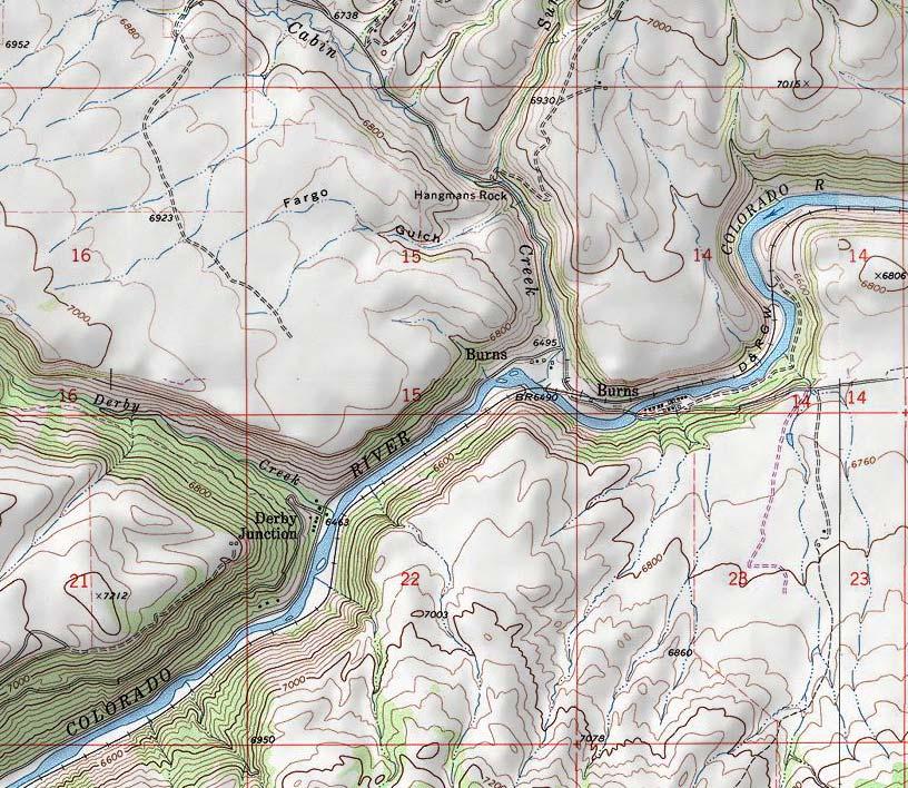
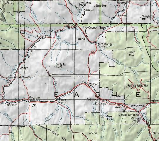
3 Burns Bridge Replacement Project No Geotechnical Investigation 1.0 PROJECT INFORMATION 1.1 Purpose and Scope This report presents the results of our geotechnical investigation for the design and construction of the bridge replacement across the Colorado River near Burns, Colorado. The project site is located at mile marker 23.5 on Colorado River Road, also known as County Road 301, in Eagle County, Colorado (Figure 1). The purpose of this study was to evaluate general geotechnical characteristics of the onsite soils and rock and provide geotechnical recommendations for the proposed new replacement bridge. The geotechnical investigation consisted of geologic reconnaissance and exploratory test hole drilling to investigate general subsurface conditions. Test hole drilling was observed by a representative of Yeh and Associates. Samples obtained during the field exploration were examined by the project personnel and representative samples were subjected to laboratory testing to determine the engineering characteristics of materials encountered. This report summarizes our field investigation, the results of our analysis and our conclusions and recommendations based on the proposed construction, site reconnaissance, subsurface investigation, and results of the laboratory testing. 1.2 Proposed Construction A new bridge is proposed over the Colorado River to replace the existing Colorado River Road (CR 301) Burns Bridge that was originally constructed in The exact location and size of the proposed bridge were undecided at the time of the drilling investigation. Plans dated November 16, 2012 provided by the client show the structure situated approximately 42 to 53 feet to the south of the existing bridge (centerline to centerline). The proposed structure will be approximately 35 feet wide by 283 feet long and consist of 3 spans. The proposed bridge deck elevation will be approximately 6,486 to 6,491 feet and will be approximately 2 to 7 feet higher than the existing bridge. Based on the plans provided, we estimate fills of up to 15 feet would be necessary for new abutments and approaches. Approximately 576 feet of roadway will be reconstructed for the new approaches and transitions with 260 feet of reconstruction west of the bridge and 316 feet of reconstruction east of the bridge. We understand that pavement design for the approaches will be provided by others. The proposed bridge abutments and piers will 1
4 Burns Bridge Replacement Project No Geotechnical Investigation likely be founded on a deep foundation system, such as driven piles or drilled shafts due to potential river scour. 1.3 Site Conditions The project site was located at the existing Burns Bridge near Burns in Eagle County, Colorado and approximately 20 miles northnorthwest of the Town of Eagle near Mile Post 23.5 on Colorado River Road. Existing grades on Colorado River Road sloped down westerly to the bridge at approximately 6 to 7 percent and sloped up westerly from the bridge at approximately 2 percent. The existing bridge deck grade varied between nearly level to 1 percent. Railroad tracks were approximately 150 feet upslope from the west end of the bridge. Vacant property and residential buildings were located adjacent to the project site. The Colorado River was approximately 200 feet wide in the area of the proposed bridge. The existing Burns Bridge over the Colorado River was approximately 211 feet long by 16 feet wide. River water level was approximately 18.5 feet below the existing bridge deck at the time of our investigation. The existing bridge was a six span steel structure with concrete and steel wall abutments and piers. The existing bridge deck construction consisted of asphalt over wood planking. 1.4 Site Geology The site is located west of, and adjacent to, unincorporated Burns, Colorado where the Burns Bridge crosses the Colorado River on Colorado River Road (C.R. 301), approximately 20 miles northnorthwest of Interstate 70 at Eagle, Colorado. The bridge area lies along the axis and near the northwest end of the Burns Syncline, a structural trough of rock layers, that terminates near Vail, Colorado, to the southeast. Exposed in slope outcrops in the project area were the variegated sandstone, siltstone, mudstone, shale and limestone of the Jurassic age Morrison Formation. Cliff outcrops overlying the Morrison Formation are the gray to yellowtan sandstone of the Jurassic age Dakota Sandstone. Surficial deposits at the site included alluvium, consisting of silt, sand, gravels, cobbles and boulders with interbedded streamchannel and flood plain deposits at and near the river, and colluvium consisting of clay, silt, sand, gravels, cobbles and boulders of locally derived material. Clays and surficial deposits derived from the Morrison Formation may be expansive. 2
5 Burns Bridge Replacement Project No Geotechnical Investigation 2.0 SITE INVESTIGATION 2.1 Subsurface Investigation Four test holes were drilled between November 8 and November 23, Test holes TH1 and TH2 were drilled through the existing bridge deck near anticipated (projected) pier locations. Test holes TH3 and TH4 were drilled near anticipated abutment locations. Test hole depths were drilled between 21 and 49 feet below the existing ground surface level. The exact location and size of the proposed bridge were undecided at the time of the drilling investigation. The locations of the test holes are presented in Figure 2. All test holes were advanced using a CME 55 truck drill rig and alternated odex, rotary, core and 4inch continuous flight auger drilling methods to predetermined depths where a modified California or split spoon sampler was used to record blow counts and obtain samples. Core samples were boxed and transported to the laboratories at Yeh and Associates in Glenwood Springs, Colorado. To perform the modified California penetration resistance tests, a 2.0inch inside diameter sampler was seated at the bottom of the test hole, then driven up to 12 inches with blows of a standard hammer weighing 140 pounds and falling a distance of 30 inches utilizing a cat head hammer (ASTM D1586). The number of blows (Blow Count) required to drive the sampler 12 inches or a fraction thereof, constitutes the Nvalue. The Nvalue, when properly evaluated, is an index of the consistency or relative density of the material tested. Split spoon samples are obtained in the same manner, but with a 1.5inch inside diameter sampler. Test hole logs and legend are presented in Appendix A. An engineering geology sheet with test hole locations will be provided. 2.2 Subsurface Conditions In general, the subsurface conditions in the bridge area consist of 16 to 29 feet of medium dense to very dense sand, gravel and occasional cobbles and boulders over sandstone and shale bedrock. Difficult coring in TH1 destroyed the ream shell at 33 feet where coring operations were stopped. Drilling in TH2 ceased at 21 feet due to core equipment issues. In TH3, odex drilling was attempted to 29 feet when bedrock material was too soft for the hammer to penetrate. Test boring was switched to coring method. Coring began at 29 feet in TH3 and 3
6 Burns Bridge Replacement Project No Geotechnical Investigation was stopped at 33.5 feet when the drill became too plugged to continue. Drilling again resumed in TH3 using 4inch continuous flight auger to refusal at 47 feet. Odex drilling in TH4 was stopped at 30 feet and drilling resumed using rotary drilling to the final depth of 49 feet. Bedrock was encountered at elevations of 6,445 to 6,459 feet, or depths of 16 to 29 feet. The elevation of the bridge deck was considered to be 6,484 feet. Sandstone and claystone bedrock samples were subjected to unconfined compression testing. Test results indicated compressive strengths of 11 and 197 psi for claystone bedrock and 8,220 psi for sandstone bedrock. Two abutment samples were subjected to resistivity, ph, sulfate and chloride testing. See Section 6.0 for chemical test results. In general, the sandstone bedrock was hard to very hard and slightly weathered with some iron staining in fractures. Samplers and SPT tests were not able to advance through this hard bedrock and bounced at many depths where SPT tests were conducted. The claystone bedrock was also hard and slightly weathered with some clay infilling in partings between layers. One sample was taken at the edge of the river bank as a representative scour sample. Testing of the scour sample consisted of 85 percent gravel and was nonliquid and nonplastic. This gravel sample classified as GP (USCS) and as A1a (AASHTO). Results of the laboratory testing are summarized in the Summary of Laboratory Test Results, and are presented in Appendix B Groundwater Groundwater was encountered at estimated elevations of 6,464 and 6,463 feet, or depths of 20 feet and 22 feet in TH3 and TH4, respectively, at the time of drilling. TH1 and TH2 were both drilled from the existing bridge deck at an elevation of approximately 6,484 feet, above the Colorado River into the river bed which was at an elevation of 6,462 feet at test hole TH1 and 6,463 feet at test hole TH2. Variations in groundwater conditions may occur seasonally. The magnitude of the variation will be largely dependent upon the adjacent Colorado River water level, the amount of spring snowmelt, duration and intensity of precipitation, site grading changes, and the surface and subsurface drainage characteristics of the surrounding area. 4
7 Burns Bridge Replacement Project No Geotechnical Investigation 2.3 Site Grading At the time of our investigation, a proposed southeast to northwest alignment was suggested by the client for preliminary design purposes. Based on the plans dated November 16, 2012 provided by the client, we anticipate up to 15 feet of fill would be required for new abutments and approaches. The embankment should be sloped at an angle of 2 horizontal to 1 vertical, or flatter. We believe the materials encountered at this site may be excavated with conventional heavy equipment. All areas requiring fill should be stripped of vegetation, organic soils and debris. Topsoil is not recommended for fill material. Fill should be placed in thin, loose lifts of 8 inches thick or less. The onsite soils free of organic matter, debris and rocks larger than 6 inches can be used in fills. We recommend fill materials be placed in accordance with the Colorado Department of Transportation Standard Specifications for Road and Bridge Construction. Placement and compaction of fill should be observed and tested by a representative of the geotechnical engineer. 3.0 FOUNDATION RECOMMENDATIONS The foundation recommendations contained herein, generally comply with AASHTO for either ASD 1 (Allowable Stress Design) or LRFD 2 (Load Resistance Factor Design). 3.1 Bridge Foundation Considerations Based on the results of our subsurface investigation, we recommend the proposed bridge abutments and piers be supported on either driven Hpile or drilled shaft foundations. The piles or drilled shafts should be founded in bedrock. In addition, boulders may be encountered in overburden materials and would likely require predrilling and/or blasting at pile locations. Our investigation boulders were predominately encountered at depths of 0 to 8 feet. Based on test hole drilling, we estimate the bedrock surface at approximately 16 to 18 feet below grade or 1 AASHTO, (2002). Standard Specifications for Highway Bridges, 17 th Edition, American Association of State Highway and Transportation Officials, Washington, D.C. 2 AASHTO, (2010). AASHTO LRFD Bridge Design Specifications, 5 th Edition, American Association of State Highway and Transportation Officials, Washington, D.C. 5
8 Burns Bridge Replacement Project No Geotechnical Investigation elevations of 6,445 to 6,446 feet for bridge piers and at approximately 26 to 29 feet below grade or elevations of 6,455 to 6,459 feet for abutments. We anticipate driven piles would penetrate 3 to 5 feet into bedrock. If additional penetration is required, we recommend the driven pile locations be predrilled to facilitate bedrock penetration. Groundwater will likely be encountered between elevations of 6,463 and 6,466 feet. Temporary casing would likely be required to facilitate drilled shaft installation. The effects of scour (estimated by others) such as, water loading and reduction of soil support, should be accounted for in the horizontal and axial design of the deep foundations. Generally, the top of the deep foundations is installed below the scour depth. Recommendations for driven piles and drilled shafts are presented below Driven Steel HPile 1. For Allowable Stress Design (ASD) criteria, steel Hpile driven into bedrock may be designed for an axial allowable compressive stress of 9 ksi times the crosssectional area of the pile for Grade 36 steel or 12 ksi for Grade 50 steel. For design of an HP12x53 pile section in axial tension, we recommend using 15 percent of the axial allowable compressive stress plus the weight of the pile for center pier locations and 25 percent for abutments. Other pile sizes should be evaluated. Estimated bedrock elevations and pile tip elevations are shown below: Table 1 Bedrock and Estimated Pile Tip Elevations Location Bedrock Elevation* Estimated Pile Tip Elevation* West Abutment West Pier East Pier East Abutment *Existing bridge deck center assumed at elevation 6484 feet. 2. Using Load Resistance Factor Design (LRFD) criteria, steel Hpile driven into bedrock may be designed for a maximum combined end bearing and skin friction nominal bearing axial compression resistance of 27 ksi for Grade 36 steel or 33 ksi for Grade 50 steel, times the cross sectional area of the pile. The factored bearing resistance is the product of the nominal bearing resistance and the resistance factor. A resistance factor of 0.65 may be used provided that a minimum number of piles are dynamically monitored according to AASHTO Table Resistance Factors for Driven Piles and the driving criteria is established by signal matching at the beginningofrestrike (BOR); otherwise, the resistance factor is The maximum factored resistance should be checked against the structural strength limit state for piling. 6
9 Burns Bridge Replacement Project No Geotechnical Investigation 3. Driven piles should be installed per CDOT Standard Specifications for Road and Bridge Construction, Section 502 (Piling) dated The piles should be driven without damage to a refusal criteria defined as 10 blows per inch into bedrock. A range of acceptable manufacturer rated hammer energies should be specified in the Contract per CDOT Section (a) (3.) that are based on Wave Equation Analyses. Yeh and Associates, Inc. can provide these analyses once a pile size and type has been determined. 4. Based on the results of our field exploration, laboratory testing and our experience with similar properly constructed driven pile foundations, we estimate individual pile settlement will be less than ½ inch when designed according to the criteria presented in this report. 5. The upper 3 feet of pile penetration should be neglected for lateral load resistance calculation. For lateral loading analysis using LPILE program, the following parameters may be used: Material Table 2 LPILE Program Lateral Loading Parameters Soil Model Friction Angle, φ (deg) Cohesion, c (psf) Horizontal Modulus of Subgrade Reaction, k h (pci) ε 50 Effective Unit Weight, γ (pcf) Saturated Unit Weight, γ (pcf) Structural Reese Fill Sand Sand above Reese groundwater Sand Sand and gravel Reese below Sand groundwater Bedrock Stiff Clay Groups of piles will also require appropriate reductions of the lateral capacities based on shadowing and other group effects. The minimum spacing requirements between piles should be three diameters from center to center. For lateral loading, recommended P multipliers should comply with AASHTO LRFD Table to account for lateral group effects. Reductions for axial capacities are not necessary for piles driven to bedrock through granular soil at three diameter spacing or greater. 7. Steel reinforcement pile tips are required on the ends of the steel HP sections for protection. 7
10 Burns Bridge Replacement Project No Geotechnical Investigation Drilled Shafts 1. For Allowable Stress Design (ASD) criteria, drilled shafts embedded in the hard bedrock may be designed for an allowable end bearing pressure of 60 ksf and a skin friction of 6 ksf for the portion of drilled shaft in bedrock. 2. Using Load Resistance Factor Design (LRFD) criteria, an end bearing nominal bearing capacity of 180 ksf and a nominal side shear capacity of 18 ksf for that portion of the drilled shaft embedded into bedrock may also be used. We recommend resistance factors of 0.60 and 0.55 for side shear and end bearing, respectively. Settlement of the structure using the LRFD method should be checked against loadings obtained based on service limit state. 3. Drilled shafts should penetrate a minimum of 5 feet into bedrock or 2 times the shaft diameter, whichever is greater. 4. Bedrock may be very hard at various elevations and vary in consistency from claystone to shale to sandstone. The contractor should mobilize equipment of sufficient size and operating condition to achieve the required design bedrock penetration. 5. The upper 3 feet of drilled shaft penetration should be neglected for lateral load resistance calculation. For lateral loading analysis using LPILE program, the parameters from Table 2 of the Driven Steel HPile Section may be used. 6. The minimum spacing requirements between drilled shafts should be three diameters from center to center. For consideration of group effects the recommendations in item 6 of the driven Steel Hpile Section may be used. Additional capacity reduction factors can be provided if required for conditions other than those anticipated. 7. The presence of water in the exploratory test holes indicates casing and/or dewatering equipment will be required. In no case should concrete be placed in more than 3 inches of water unless the tremie method is used. If water cannot be removed or prevented with the use of casing and/or dewatering equipment prior to placement of concrete, the tremie method, as described in the CDOT s 2011 Standard Specifications for Road and Bridge Construction, should be used. 8. A representative of the soils engineer should observe drilled shaft drilling operations on a fulltime basis. 3.2 Lateral Earth Pressure Bridge retaining/wing walls should be designed to resist lateral earth pressure. We recommend all retaining/wing walls are backfilled with CDOT Class 1 Structure Backfill. Walls can be designed using an equivalent fluid density of 35 pcf for active or 55 pcf for at rest conditions for 8
11 Burns Bridge Replacement Project No Geotechnical Investigation Class 1 Structure Backfill. This equivalent fluid density assumes a horizontal slope above the wall. This value also assumes that the backfill materials are not saturated. Wall designs should consider the influence of surcharge loading such as traffic, construction equipment and/or sloping backfill. Retaining/wing walls should be constructed with a drainage system to drain away any excess water immediately behind the wall. The drainage system may consist of freedraining gravel, pipes, drain board and/or weep holes are commonly used for the wall drainage. 4.0 BRIDGE APPROACH SETTLEMENT Based on subsurface conditions, anticipated abutment elevation and our experience, we believe that potential settlement of bridge approaches would be minor. Subsoils below the bridge approaches consisted of medium to very dense sands with gravels, cobbles and boulders. We believe these materials would exhibit low consolidation after placement of new fill at the approaches. We estimate fill depths of up to 15 feet for bridge approaches. Total settlement of less than 1inch should be anticipated. 5.0 SEISMIC CONSIDERATIONS The project is located at approximate latitude and longitude The site is classified as Site Class D in accordance with Table of the AASHTO LRFD Bridge Design Specifications. The Peak Ground Acceleration (PGA), and the short and longperiod spectral acceleration coefficients (Ss and S1 respectively) for the Burns bridge site were obtained using the USGS 2007 Seismic Parameters for an event with a 7% Probability of Exceedance (PE) in 75 years and a Site Class B (reference site). An event with the above probability of exceedance has a return period of about 1,000 years. The values were adjusted using Site Factors for Site Class D in accordance with Section of the AASHTO LRFD Bridge Design Specifications. The seismic parameters for this site are shown on the tables below. 9
12 Burns Bridge Replacement Project No Geotechnical Investigation Table 3 Seismic Design Parameters PGA (0.0 sec) Ss (0.2 sec) S1 (1.0 sec) Table 4 Seismic Design Parameters for Site Class D As (0.0 sec) SDs (0.2 sec) SD1 (1.0 sec) Seismic Zone g g g FOUNDATION CONCRETE AND CORROSIVITY The concentrations of watersoluble sulfates measured in the laboratory on the near surface samples varied from and percent in test holes TH4 and TH3, respectively. These concentrations of watersoluble sulfates represent a negligible/low (Class 0 exposure) degree of sulfate attack on concrete exposed to these materials. The degree of attack is based on a range of 0.00 to less than 0.10 percent as presented in the American Concrete Institute Guide to Durable Concrete. Due to the negligible/low degree indicated by the test results, no special requirements for concrete are necessary for Class 0 exposure. The ph and electrical resistivity was determined for selected samples. Test results measured ph values at 6.8 and 7.4 in test holes TH4 and TH3, respectively. Resistivity measurements were 513 and 1083 ohmcentimeters and watersoluble chlorides were and percent in test holes TH4 and TH3, respectively. A qualified corrosion engineer should review this data to determine the appropriate level of corrosion protection. 7.0 LIMITATIONS This study was conducted in accordance with generally accepted geotechnical engineering practices in this area for use by the client for design purposes. The conclusions and recommendations submitted in this report are based upon the data obtained from exploratory test holes, field reconnaissance and anticipated construction. The nature and extent of subsurface variations across the site may not become evident until excavation is performed. If during construction, conditions appear to be different from those described herein; this office should be advised at once so reevaluation of the recommendations may be made. We 10
13 Burns Bridge Replacement Project No Geotechnical Investigation recommend onsite observation of excavations by a representative of the geotechnical engineer. The scope of services for this project did not include, specifically or by implication, any environmental or biological (e.g., mold, fungi, and bacteria) assessment of the site or identification or prevention of pollutants, or conditions or biological conditions. If the owner is concerned about the potential for such contamination, conditions or pollution, other studies should be undertaken. A hazardous material evaluation is to be provided in a separate report. The report was prepared in substantial accordance with the generally accepted standards of practice for geotechnical engineering as exist in the site area at the time of our investigation. No warranties, express or implied, are intended or made. Respectfully Submitted: YEH AND ASSOCIATES, INC. Reviewed by: Keith E. Asay Staff Engineer Richard D. Johnson, P.E. Project Manager Paul Macklin, P.E. Principal Engineer 11
14
15
16 Burns Bridge Replacement Project No Geotechnical Investigation APPENDIX A Drill Logs, Legend and Core Pictures
17 TH4 West abutment boring Elevation: 6485 ft TH3 East abutment boring Elevation: 6484 ft 6,480 ph= 6.8 S= % Re= 513ohmscm ph= 7.4 S= 0.014% Re= 1083ohmscm 6,480 6,470 23/12 TH1 West pier boring Elevation: 6462 ft TH2 East pier boring Elevation: 6463 ft 19/12 6,470 50/0 6,460 6,460 6,450 50/0 83%/0 36/12 80%/47% 100%/0 6,450 Elevation (ft) 6,440 6,430 6,420 50/0 50/0 76%/11% 100%/63% 72%/45% 60%/0 DD= 165.0pcf UCCS= psf MC= 12% DD= 117.0pcf LL= 33 PL= 21 UCCS= 1535psf MC= 11% DD= 115.0pcf LL= 29 PL= 20 MC= 3% DD= 146.0pcf UCCS= 28319psf 50/0 50/0 6,440 6,430 6,420 FENCES BY ELEVATION A SIZE BORING LOGS.GPJ RDJ.GDT 12/6/12 6,410 6,400 6,390 YEH AND ASSOCIATES, INC. GEOTECHNICAL ENGINEERING CONSULTANTS Project Number: Burns Bridge Replacement 6,410 6,400 6,390 Figure No. A1
18 YEH AND ASSOCIATES, INC. GEOTECHNICAL ENGINEERING CONSULTANTS Project: Burns Bridge Replacement Project Number: Legend for Symbols Used on Borehole Logs Sample Types Bulk sample was obtained from auger cuttings at the depths indicated. Rock Core. The symbol 76%/11% indicates 76% recovery in core barrel and a Rock Quality Designation (RQD) of 11% for the length of core shown. Modified California Sampler. The symbol 16/12 indicates that 16 blows from a 140 pound hammer falling 30 inches was used to drive 2inch I.D. sampler 12 inches. Other Symbols Indicates practical drill rig refusal. Indicates approximate groundwater or river depth and elevation at time of drilling. Indicates approximate groundwater or river depth and elevation on December 4, Soil Lithology GRAVEL, sandy, interlayered with cobbles and boulders. See detailed, graphical drill logs. SAND, gravelly with cobbles and boulders. See detailed, graphical drill logs SAND, silty. See detailed, graphical drill logs. SILT, sandy. See detailed, graphical drill logs. Bedrock Lithology CLAYSTONE, sandy, slightly moist, hard to very hard, brown, red, olive. SANDSTONE, slightly moist, hard to very hard, brown, tan, redbrown. Lab Test Abbreviations MCMoisture Content DDDry Density LLLiquid Limit PLPlastic Limit UCCSUnconfined Compressive Strength SWater Soluble Sulfates ReResistivity NOTES: 1. Test holes were odexed, cored and/or drilled with 3 and 4inch continuous flight auger on November 9, 10, 15 and 16, Test hole descriptions are subject to explanations contained in this report. 3. Existing bridge deck at center point elevation estimated 6,484 feet based on topographic map by others. Figure No. A2
19 YEH AND ASSOCIATES, INC. GEOTECHNICAL ENGINEERING CONSULTANTS Project: Burns Bridge Replacement Project Number: Boring: TH1 Sheet 1 of 1 Boring Began: 11/9/2011 Drilling Method: Odex and Core Drill: CME 55 Driller: Ager Drilling Logged By: K. Asay Final By: K. Asay Inclination: Vertical Ground Water Notes: Drill river bed Depth Date Time Completed: 11/9/2011 Drill Bit: NX Casing: Steel Casing Weather: Clear, cold 3.5 ft 11/9/ ft 12/4/12 Total Depth: 33.0 ft Ground Elevation: ft Location: West pier boring Coordinates: N: 1.0 E: 2.0 Elevation (feet) Depth (feet) Run / Sample Type Recovery (%) Rock RQD Soil Samples SPT Blows per 6 in N Lithology Material Description Field Notes and Lab Tests ft. silty SAND, brown, wet, (alluvium). Began odex drilling in river bed ft. sandy GRAVEL with cobbles, brown, wet, (alluvium) ft. silty SAND, brown, wet, (alluvium) ft. sandy SILT, brown, wet, (alluvium) ft. SANDSTONE BEDROCK, gray, very hard, joint, joint spacing close, open fractures, iron stains, smooth surfaces, (MORRISON FORMATION). Odex in bedrock at 16 feet. BORING LOG BORING LOGS.GPJ RDJ.GDT 12/6/ ft. CLAYSTONE BEDROCK, gray, hard, parting clay infilling, (MORRISON FORMATION) ft. Plugged off. Ream shell destroyed at 33 feet. Drilling ceased.. Bottom of Hole at 33.0 ft. Switch to coring in bedrock at 21 feet. DD= 165.0pcf UCCS= psf 18 minutes to drill 1.5 feet. MC= 12% DD= 117.0pcf LL= 33 PL= 21 UCCS= 1535psf 8 minutes to drill 2.5 feet. MC= 11% DD= 115.0pcf LL= 29 PL= minutes to drill 4 feet. Plugged 28 feet. MC= 3% DD= 146.0pcf UCCS= 28319psf 35 minutes to drill 4 feet.
20 YEH AND ASSOCIATES, INC. GEOTECHNICAL ENGINEERING CONSULTANTS Project: Burns Bridge Replacement Project Number: Boring: TH2 Sheet 1 of 1 Boring Began: 11/10/2011 Drilling Method: Odex Drill: CME 55 Driller: Ager Drilling Logged By: K. Asay Final By: K. Asay Inclination: Vertical Ground Water Notes: Drill river bed Depth Date Time Completed: 11/10/2011 Drill Bit: Casing: Steel Casing Weather: Clear, cold 2.5 ft 11/10/ ft 12/4/12 Total Depth: 21.0 ft Ground Elevation: ft Location: East pier boring Coordinates: N: 1.0 E: 3.0 Elevation (feet) Depth (feet) Run / Sample Type Recovery (%) Rock RQD Soil Samples SPT Blows per 6 in N Lithology Material Description Field Notes and Lab Tests ft. silty SAND, brown, wet, (alluvium). Started odex drilling in river bed ft. gravelly SAND with silt, brown, wet, (alluvium) ft. sandy GRAVEL with cobbles and boulders, brown, wet, (alluvium). Cobbles and boulders up to 18 inch diameter ft. gravelly SAND with silt, cobbles and boulders, brown, wet, (alluvium) ft. sandy GRAVEL boulders, brown, wet, (alluvium). Boulders up to 18 inch diameter ft. silty SAND, brown, wet, (alluvium) ft. SANDSTONE BEDROCK, gray, very hard, (MORRISON FORMATION). BORING LOG BORING LOGS.GPJ RDJ.GDT 12/6/ Bottom of Hole at 21.0 ft. Stopped odex to switch to coring at 21 feet. Drill required new parts before coring. Coring abandoned for this test hole.
21 YEH AND ASSOCIATES, INC. GEOTECHNICAL ENGINEERING CONSULTANTS Project: Burns Bridge Replacement Project Number: Boring: TH3 Sheet 1 of 2 Boring Began: 11/15/2011 Drilling Method: Odex, Core and Auger Drill: CME 55 Driller: Ager Drilling Logged By: S. White Ground Water Notes: Final By: S. White Depth Date Inclination: Vertical Time Elevation (feet) Depth (feet) Run / Sample Type Recovery (%) Rock RQD Soil Samples SPT Blows per 6 in Completed: 11/17/2011 Drill Bit: NX Casing: Steel Casing Weather: Clear, cold N 20.0 ft 11/15/11 Lithology Material Description Total Depth: 47.0 ft Ground Elevation: ft Location: East abutment boring Coordinates: N: 1.0 E: 4.0 Field Notes and Lab Tests ft. sandy GRAVEL with cobbles and boulders, brown, slightly moist, dense to very dense, (alluvium/colluvium). Odex drilling started at surface. ph= 7.4 S= 0.014% Re= 1083ohmscm ft. gravelly SAND with silt, cobbles and boulders, brown, slightly moist, medium dense, (alluvium/colluvium). Boulders and cobbles up to 24 inches diameter encountered in first 5 feet /12 Drilling stopped for repair of shoe for odex at 10 feet ft. silty SAND with gravels, brown, slightly moist to wet, medium dense, (alluvium/colluvium). Drilling fast in soft materials to 20 feet Driller couldn't get bit to release from casing at 20 feet. Drilling continued in soft material BORING LOG BORING LOGS.GPJ RDJ.GDT 12/6/ / ft. SANDSTONE BEDROCK, gray, very hard, open fractures, iron stains, smooth surfaces, (MORRISON FORMATION) ft. CLAYSTONE BEDROCK, gray, hard, (MORRISON FORMATION). At 29 feet, material too soft for odex hammer. Changed to coring. Core bit plugging at 34 feet. Changed to auger drilling. Auger refusal.
22 YEH AND ASSOCIATES, INC. GEOTECHNICAL ENGINEERING CONSULTANTS Project: Burns Bridge Replacement Project Number: Boring: TH3 Sheet 2 of 2 Elevation (feet) Depth (feet) Run / Sample Type Recovery (%) Rock RQD Soil Samples SPT Blows per 6 in N Lithology Material Description Field Notes and Lab Tests ft. (CLAYSTONE BEDROCK continued, MORRISON FORMATION). Driller retried auger and drilled to 47 feet / /0 Bottom of Hole at 47.0 ft. Auger refusal BORING LOG BORING LOGS.GPJ RDJ.GDT 12/6/
23 YEH AND ASSOCIATES, INC. GEOTECHNICAL ENGINEERING CONSULTANTS Project: Burns Bridge Replacement Project Number: Boring: TH4 Sheet 1 of 2 Boring Began: 11/16/2011 Drilling Method: Odex and Rotary Drill: CME 55 Driller: Ager Drilling Logged By: S. White Final By: S. White Inclination: Vertical Elevation (feet) Depth (feet) Run / Sample Type Recovery (%) Rock RQD Ground Water Notes: Depth Date Time Soil Samples SPT Blows per 6 in Completed: 11/16/2011 Drill Bit: Casing: Steel Casing Weather: Clear, cold N 22.0 ft 11/16/11 Lithology Material Description Total Depth: 49.0 ft Ground Elevation: ft Location: West abutment boring Coordinates: N: 1.0 E: 1.0 Field Notes and Lab Tests ft. gravelly SAND with silt, cobbles and boulders, brown and rust, slightly moist, medium dense, (alluvium/colluvium). ph= 6.8 S= % Re= 513ohmscm / ft. sandy GRAVEL and BOULDERS, brown, slightly moist, very dense, (alluvium/colluvium) ft. gravelly SAND with silt, cobbles and boulders, brown and rust, slightly moist to wet, medium dense, (alluvium/colluvium). Approximate 4 foot diameter boulder encountered at depth of 3.5 feet. Up to 24 inch diameter cobbles and boulders encountered. Drill head jammed at 10 feet. Stopped for repair. No cuttings return available for sampling from odex drilling from 10 to 20 feet / ft. silty SAND with clay, few gravels, brown, wet, (alluvium/colluvium). BORING LOG BORING LOGS.GPJ RDJ.GDT 12/6/ / ft. SANDSTONE BEDROCK, gray, very hard, (MORRISON FORMATION) ft. CLAYSTONE BEDROCK, gray, medium hard to hard, (MORRISON FORMATION). Changed to rotary drilling at 30 feet.
24 YEH AND ASSOCIATES, INC. GEOTECHNICAL ENGINEERING CONSULTANTS Project: Burns Bridge Replacement Project Number: Boring: TH4 Sheet 2 of 2 Elevation (feet) Depth (feet) Run / Sample Type Recovery (%) Rock RQD Soil Samples SPT Blows per 6 in N Lithology Material Description Field Notes and Lab Tests ft. (CLAYSTONE BEDROCK continued, MORRISON FORMATION) / /0 Bottom of Hole at 49.0 ft BORING LOG BORING LOGS.GPJ RDJ.GDT 12/6/


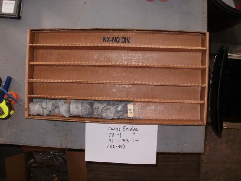
25 Drill Core from test hole TH1 at 21 feet to 31 feet Drill Core from test hole TH1 at 31 feet to 33 feet

26 Drill Core from test hole TH3 at 29 feet to 33.5 feet
27 Burns Bridge Replacement Project No Geotechnical Investigation APPENDIX B Laboratory Test Results and Summary Table
28 Sieve Analysis Hydrometer Analysis Sieve Opening in Inches U.S. Standard Sieves Size of Particles in mm " 6" 3" 2" 1" 3/4" 1/2" 3/8" Sieve Size 3" % Passing ½" " ½" 55 Percent Passing " ¾ " ½" ⅜" # # # Particle Size (mm) #200 3 Gravel (%) Sand (%) Fines (%) 3 PI NP Sample Description: LL PL NL NP Gravel with sand (GP) Project Name: Sample ID: Sample Depth (ft.): Burns Bridge Replacement Streambed 0 Drawn By: Checked By: Yeh & Associates, Inc. Geotechnical Engineering Consultants SIEVE ANALYSIS SW RDJ Project No.: Figure No.: B1 Revised 04/22/2004
29 YEH & ASSOCIATES, INC Summary of Laboratory Test Results Project No: Project Name: Burns Bridge Replacement Sample Location Grain Size Analysis Atterberg Limits Water Water Unconfined Moisture Dry Gravel Fines Soluble Soluble Resistivity Compressive Test Sample Content Density Sand ph Soil Description Depth (ft) > #4 < #200 LL PL PI Sulfate Chloride (ohmcm) Strength Hole Type (%) (pcf) (%) (%) (%) (%) (%) (psf) (psi) Stream 0 Bulk NL NP NP Gravel with sand (GP) bed TH Core 165 1,183, Sandstone Bedrock Core , Claystone Bedrock Core Claystone Bedrock Core , Claystone Bedrock TH3 010 Bulk Sand, gravelly with silt TH4 010 Bulk Sand, gravelly with silt NL Indicates nonliquid NP Indicates nonplastic Page 1 of 1
Geotechnical Engineering Report
 Geotechnical Engineering Report Turner Turnpike Widening Bridge B Bridge Crossing: South 257 th West Avenue Creek County, Oklahoma June 1, 2016 Terracon Project No. 04155197 Prepared for: Garver, LLC Tulsa,
Civil Engineering, Surveying and Environmental Consulting WASP0059.ltr.JLS.Mich Ave Bridge Geotech.docx
 2365 Haggerty Road South * Canton, Michigan 48188 P: 734-397-3100 * F: 734-397-3131 * www.manniksmithgroup.com August 29, 2012 Mr. Richard Kent Washtenaw County Parks and Recreation Commission 2330 Platt
Geotechnical Engineering Study, Conifer Senior High School Football Field Improvements, Conifer, Colorado
 2390 South Lipan Street Denver, CO 80223 phone: (303) 742-9700 fax: (303) 742-9666 email: kadenver@kumarusa.com www.kumarusa.com Office Locations: Denver (HQ), Colorado Springs, Fort Collins, and Frisco,
Geotechnical Engineering Report
 Geotechnical Engineering Report Turner Turnpike Widening Bridge D Bridge Crossing: South 209 th West Avenue Creek County, Oklahoma June 1, 2016 Terracon Project No. 04155197 Prepared for: Garver, LLC Tulsa,
B-1 BORE LOCATION PLAN. EXHIBIT Drawn By: 115G BROOKS VETERINARY CLINIC CITY BASE LANDING AND GOLIAD ROAD SAN ANTONIO, TEXAS.
 N B-1 SYMBOLS: Exploratory Boring Location Project Mngr: BORE LOCATION PLAN Project No. GK EXHIBIT Drawn By: 115G1063.02 GK Scale: Checked By: 1045 Central Parkway North, Suite 103 San Antonio, Texas 78232
Geotechnical Engineering Report
 Geotechnical Engineering Report Turner Turnpike Widening Polecat Creek Bridge (Bridge A) June 1, 2016 Terracon Project No. 04155197 Prepared for: Garver, LLC Prepared by: Terracon Consultants, Inc. TABLE
 Project: ITHACA-TOMPKINS REGIONAL AIRPORT EXPANSION Project Location: ITHACA, NY Project Number: 218-34 Key to Soil Symbols and Terms TERMS DESCRIBING CONSISTENCY OR CONDITION COARSE-GRAINED SOILS (major
June 9, R. D. Cook, P.Eng. Soils Engineer Special Services Western Region PUBLIC WORKS CANADA WESTERN REGION REPORT ON
 PUBLIC WORKS CANADA WESTERN REGION REPORT ON GEOTECHNICAL INVESTIGATION PROPOSED MARTIN RIVER BRIDGE MILE 306.7 MACKENZIE HIGHWAY Submitted by : R. D. Cook, P.Eng. Soils Engineer Special Services Western
Geotechnical Data Report
 Geotechnical Data Report Downtown Greenville Future Conveyance Study December 1, 2015 Terracon Project No. 86155032 Prepared for: Prepared by: Terracon Consultants, Inc. December 1, 2015 561 Mauldin Road
December 5, Junction Gateway, LLC 7551 W. Sunset Boulevard #203 Los Angeles, CA Mr. James Frost P: Dear Mr.
 December 5, 2014 Junction Gateway, LLC 7551 W. Sunset Boulevard #203 90046 Attn: Re: Mr. James Frost P: 323.883.1800 Geotechnical Update Letter Sunset & Effie Mixed Use Development 4301 to 4311 Sunset
ATTACHMENT A PRELIMINARY GEOTECHNICAL SUMMARY
 ATTACHMENT A PRELIMINARY GEOTECHNICAL SUMMARY Kevin M. Martin, P.E. KMM Geotechnical Consultants, LLC 7 Marshall Road Hampstead, NH 0384 603-489-6 (p)/ 603-489-8 (f)/78-78-4084(m) kevinmartinpe@aol.com
APPENDIX E SOILS TEST REPORTS
 Otsego County, NY Site Work Specifications APPENDIX E SOILS TEST REPORTS Blue Wing Services, Inc. July 1, 2010 Blue Wing Services May 20, 2010 Page 2 the site, was not made available to Empire at this
SITE INVESTIGATION 1
 SITE INVESTIGATION 1 Definition The process of determining the layers of natural soil deposits that will underlie a proposed structure and their physical properties is generally referred to as site investigation.
R.M.HARW & ASSOCIATES LTD. GEOTECHNICAL INVESTIGATION PROPOSED BRIDGE SITE. HELAVA CREEKl MILE MACKENZIE HIGHWAY E-2510 OCTOBER 16, 1973
 El R.M.HARW & ASSOCIATES LTD. GEOTECHNICAL INVESTIGATION PROPOSED BRIDGE SITE HELAVA CREEKl MILE 616.4 MACKENZIE HIGHWAY E-2510 OCTOBER 16, 1973 R,M,HARDV & ASSOCIATES LTD. CONSULTING ENGINEERING & TESTING
Northern Colorado Geotech
 PRELIMINARY GEOTECHNICAL ENGINEERING REPORT PROPOSED CECIL FARMS DEVELOPMENT WELD COUNTY ROAD 7, BETWEEN ROADS 7 AND 7 SEVERANCE, COLORADO NORTHERN COLORADO GEOTECH PROJECT NO. 0-6 APRIL 0, 06 Prepared
Chapter 12 Subsurface Exploration
 Page 12 1 Chapter 12 Subsurface Exploration 1. The process of identifying the layers of deposits that underlie a proposed structure and their physical characteristics is generally referred to as (a) subsurface
ENCE 3610 Soil Mechanics. Site Exploration and Characterisation Field Exploration Methods
 ENCE 3610 Soil Mechanics Site Exploration and Characterisation Field Exploration Methods Geotechnical Involvement in Project Phases Planning Design Alternatives Preparation of Detailed Plans Final Design
 Photo 1 - Southerly view across 2700 parking lot toward existing building. Multi-residential building borders western side of property in upper right of view. Photo 2 - Southerly view across 2750 parking
GEOTECHNICAL REPORT. Matanuska-Susitna Borough. Parks Highway Connections Museum Drive. Matanuska-Susitna Borough, Alaska.
 Matanuska-Susitna Borough GEOTECHNICAL REPORT Parks Highway Connections Museum Drive Matanuska-Susitna Borough, Alaska March 2, 20 Prepared By: John Thornley, PE Geotechnical Engineer 333 Arctic Blvd.,
B-1 SURFACE ELEVATION
 5A 5B LOGGED BY El. S. Bhangoo DRILLING CONTRACTOR Pitcher Drilling DRILLING METHOD Rotary Wash BEGIN DATE 12-14-12 SAMPLER TYPE(S) AND SIZE(S) (ID) SPT, MC BOREHOLE BACKFILL AND COMPLETION COMPLETION
Geotechnical Investigation Juneau Seawalk - Taku Fisheries to Miner s Wharf Juneau, Alaska DM&A Job No
 Duane Miller & Associates 5821 Arctic Boulevard, Suite A Anchorage, AK 99518-1654 (907) 644-3200 Fax 644-0507 Arctic & Geotechnical Engineering May 4, 2006 Tetra Tech/KCM, Inc. 1971 First Avenue Seattle,
DATA REPORT GEOTECHNICAL INVESTIGATION GALVESTON CRUISE TERMINAL 2 GALVESTON, TEXAS
 DATA REPORT GEOTECHNICAL INVESTIGATION GALVESTON CRUISE TERMINAL 2 GALVESTON, TEXAS SUBMITTED TO PORT OF GALVESTON 123 ROSENBERG AVENUE, 8TH FLOOR GALVESTON, TEXAS 77553 BY HVJ ASSOCIATES, INC. HOUSTON,
KDOT Geotechnical Manual Edition. Table of Contents
 KDOT Geotechnical Manual 2007 Edition The KDOT Geotechnical Manual is available two volumes. Both volumes are very large electronic (pdf) files which may take several minutes to download. The table of
Pierce County Department of Planning and Land Services Development Engineering Section
 Page 1 of 7 Pierce County Department of Planning and Land Services Development Engineering Section PROJECT NAME: DATE: APPLICATION NO.: PCDE NO.: LANDSLIDE HAZARD AREA (LHA) GEOLOGICAL ASSESSMENT REPORT
Limited Geotechnical Engineering Evaluation Classroom Additions Albany County Campus Laramie, Wyoming
 Limited Geotechnical Engineering Evaluation Classroom Additions Albany County Campus 2300 Missile Drive, Cheyenne, Wyoming 82001 Phone 307-635-0222 www.stratageotech.com Limited Geotechnical Engineering
Geotechnical Report Rifle Roundabouts Interstate 70 and Taughenbaugh Boulevard Rifle, Colorado
 Geotechnical Report Rifle Roundabouts Interstate 70 and Taughenbaugh Boulevard Rifle, Colorado Project No. 24129 February 9, 2005 Prepared for: Schmueser Gordon Meyer, Inc. 118 West 6 th Street, Suite
 SOIL CLASSIFICATION CHART COARSE-GRAINED SOILS MORE THAN 50% RETAINED ON NO.200 SIEVE FINE-GRAINED SOILS 50% OR MORE PASSES THE NO.200 SIEVE PRIMARY DIVISIONS GRAVELS MORE THAN 50% OF COARSE FRACTION RETAINED
Boreholes. Implementation. Boring. Boreholes may be excavated by one of these methods: 1. Auger Boring 2. Wash Boring 3.
 Implementation Boreholes 1. Auger Boring 2. Wash Boring 3. Rotary Drilling Boring Boreholes may be excavated by one of these methods: 4. Percussion Drilling The right choice of method depends on: Ground
Depth (ft) USCS Soil Description TOPSOIL & FOREST DUFF
 USCS Soil Description TOPSOIL & FOREST DUFF") Test Pit No. TP-6 Location: Latitude 47.543003, Longitude -121.980441 Approximate Ground Surface Elevation: 1,132 feet Depth (ft) USCS Soil Description 0 1.5 1.5 5.0 SM 5.0 8.0 SM Loose to medium dense,
Test Pit No. TP-6 Location: Latitude 47.543003, Longitude -121.980441 Approximate Ground Surface Elevation: 1,132 feet Depth (ft) USCS Soil Description 0 1.5 1.5 5.0 SM 5.0 8.0 SM Loose to medium dense,
Geotechnical Engineering Report
 Geotechnical Engineering Report Single-Span Bridge North Western Road & Hall of Fame Avenue August 25, 2015 Terracon Project No. 03155156 Prepared for: Olsson Associates Prepared by: Terracon Consultants,
CITY OF CAPE CORAL NORTH 2 UTILITIES EXTENSION PROJECT CONTRACT 3
 GEOTECHNICAL REPORT CITY OF CAPE CORAL NORTH UTILITIES EXTENSION PROJECT CONTRACT City of Cape Coral Procurement Division Cultural Park Boulevard, nd Floor Cape Coral, FL ISSUED FOR BID VOLUME of GEOTECHNICAL
10. GEOTECHNICAL EXPLORATION PROGRAM
 Geotechnical site investigations should be conducted in multiple phases to obtain data for use during the planning and design of the tunnel system. Geotechnical investigations typically are performed in
ENGINEERING ASSOCIATES
 July 16, 211 Vista Design, Inc. 11634 Worcester Highway Showell, Maryland 21862 Attention: Reference: Dear Mr. Polk: Mr. Richard F. Polk, P.E. Geotechnical Engineering Report Charles County RFP No. 11-9
APPENDIX C HYDROGEOLOGIC INVESTIGATION
 Figure B-5.7 Figure B-5.8 Preliminary Geotechnical and Environmental Report Appendix C Hydrogeologic Investigation APPENDIX C HYDROGEOLOGIC INVESTIGATION December 21, 2011 WESTSIDE SUBWAY EXTENSION PROJECT
AN EMPLOYEE OWNED COMPANY
 CTL Engineering, Inc. 2860 Fisher Road, P.O. Box 4448, Columbus, Ohio 43204338 Phone: 614/2768123 Fax: 614/2766377 Email: ctl@ctleng.com AN EMPLOYEE OWNED COMPANY Consulting Engineers Testing Inspection
Report of Preliminary Geotechnical Exploration. CSO-012 Sewer Separation Cincinnati, Hamilton County, Ohio. February, 2011
 11242843_GeoTech_Preliminary - Feburary 2011_1/40 Report of Preliminary Geotechnical Exploration CSO-012 Sewer Separation Cincinnati, Hamilton County, Ohio February, 2011 11242843_GeoTech_Preliminary -
APPENDIX C. Borehole Data
 APPENDIX C Borehole Data MAJOR DIVISIONS SOIL CLASSIFICATION CHART SYMBOLS GRAPH LETTER TYPICAL DESCRIPTIONS ADDITIONAL MATERIAL
M E M O R A N D U M. Mr. Jonathan K. Thrasher, P.E., Mr. Ian Kinnear, P.E. (FL) PSI
 PSI") M E M O R A N D U M TO: FROM: Mr. Mark Schilling Gulf Interstate Engineering Mr. Jonathan K. Thrasher, P.E., Mr. Ian Kinnear, P.E. (FL) PSI DATE: November 11, 2014 RE: Summary of Findings Geotechnical
M E M O R A N D U M TO: FROM: Mr. Mark Schilling Gulf Interstate Engineering Mr. Jonathan K. Thrasher, P.E., Mr. Ian Kinnear, P.E. (FL) PSI DATE: November 11, 2014 RE: Summary of Findings Geotechnical
 R-1 Conveyor Relocation Project Legend 0 500 1000 1500 ft. This map is a user generated static output from an Internet mapping site and is for general reference only. Data layers that appear on this map
REPORT OF PRELIMINARY GEOTECHNICAL EXPLORATION
 REPORT OF PRELIMINARY GEOTECHNICAL EXPLORATION ENKA INTERMEDIATE SCHOOL Sand Hill Road Candler, North Carolina Prepared For: BUNCOMBE COUNTY SCHOOLS Prepared By: AMEC ENVIRONMENT & INFRASTRUCTURE, INC.
INTRODUCTION TO STATIC ANALYSIS PDPI 2013
 INTRODUCTION TO STATIC ANALYSIS PDPI 2013 What is Pile Capacity? When we load a pile until IT Fails what is IT Strength Considerations Two Failure Modes 1. Pile structural failure controlled by allowable
REPORT OF SUBSURFACE EXPLORATION
 REPORT OF SUBSURFACE EXPLORATION GRAND RIVER DAM AUTHORITY HULBERT 69 KV SWITCHING STATION S. 440 Road Hulbert, Cherokee County, Oklahoma ENERCON PROJECT NO. GRDA006 MARCH 7, 2012 PREPARED FOR: C/O ENERCON
Field Exploration. March 31, J-U-B ENGINEERS, Inc. 115 Northstar Avenue Twin Falls, Idaho Attn: Mr. Tracy Ahrens, P. E. E:
 March 31, 201 11 Northstar Avenue 83301 Attn: Mr. Tracy Ahrens, P. E. E: taa@jub.com Re: Geotechnical Data Report Preliminary Phase 1 Field Exploration Revision No. 1 Proposed Rapid Infiltration Basin
TIERRA. Florida License No Florida License No
 March 9, 208 TIERRA AECOM 7650 West Courtney Campbell Cswy Tampa, FL 33607 Attn: RE: Mr. Edgar Figueroa, P.E. Geotechnical Engineering Services Report Purchase Order No.: 9532 AECOM Project Number: 6055499
The process of determining the layers of natural soil deposits that will underlie a proposed structure and their physical properties is generally
 The process of determining the layers of natural soil deposits that will underlie a proposed structure and their physical properties is generally referred to as sub surface investigation 2 1 For proper
PRELIMINARY GEOTECHNICAL ENGINEERING REPORT. Proposed Re-Development 44 Old Worcester Road Charlton, Massachusetts. Prepared For:
 PRELIMINARY GEOTECHNICAL ENGINEERING REPORT Proposed Re-Development 44 Old Worcester Road Charlton, Massachusetts Prepared For: Meridian Associates, Inc. 500 Cummings Center, Suite 5950 Beverly, Massachusetts
GEOTECHNICAL ENGINEERING SERVICES REPORT
 GEOTECHNICAL ENGINEERING SERVICES REPORT BRIDGE OVER BIG CREEK APPROXIMATELY.8 MILES EAST OF THE INTERSECTION OF COUNTY ROAD EW1546 AND COUNTY ROAD 193 LEFLORE COUNTY, OKLAHOMA PROJECT No. J2-8616(5),
Soil Mechanics Brief Review. Presented by: Gary L. Seider, P.E.
 Soil Mechanics Brief Review Presented by: Gary L. Seider, P.E. 1 BASIC ROCK TYPES Igneous Rock (e.g. granite, basalt) Rock formed in place by cooling from magma Generally very stiff/strong and often abrasive
LEGEND ODOT CLASS A-3. A-3a. A-4a. A-6a. A-6b TOTAL VISUAL VISUAL VISUAL BORING LOCATION - PLAN VIEW
 PROJECT THE PROJECT CONSISTS IN PART OF CONSTRUCTING A SINGLE-SPAN BRIDGE ON RELOCATED SHUMWAY HOOW ROAD OVER THE CSXT RAILROAD. THE STRUCTURE AS ANNED, IS A SINGLE-SPAN STRUCTURE WITH MSE WAS AT THE ABUTMENTS.
Geotechnical Engineering Report
 Geotechnical Engineering Report Richland Creek Trunk Sewer Greenville, South Carolina March 31, 2014 Terracon Project No. 86145008 Prepared for: Renewable Water Resources Greenville, South Carolina Prepared
Safe bearing capacity evaluation of the bridge site along Syafrubesi-Rasuwagadhi road, Central Nepal
 Bulletin of the Department of Geology Bulletin of the Department of Geology, Tribhuvan University, Kathmandu, Nepal, Vol. 12, 2009, pp. 95 100 Safe bearing capacity evaluation of the bridge site along
Ardaman & Associates, Inc. Geotechnical, Environmental and Materials Consultants
 SUBSURFACE SOIL EXPLORATION 42-INCH FORCE MAIN REPLACEMENT CHIQUITA BOULEVARD S AND SW 34 TH STREET CAPE CORAL, LEE COUNTY, FLORIDA Ardaman & Associates, Inc. Geotechnical, Environmental and Materials
Geotechnical Data Report
 Geotechnical Data Report ReWa Solar Farm at Durbin Creek Fountain Inn, South Carolina September 1, 2017 Terracon Project No. 86165043 Prepared for: Renewable Water Resources Greenville, South Carolina
APPENDIX A. Borehole Logs Explanation of Terms and Symbols
 APPENDIX A Borehole Logs Explanation of Terms and Symbols Page 153 of 168 EXPLANATION OF TERMS AND SYMBOLS The terms and symbols used on the borehole logs to summarize the results of field investigation
LEGEND ODOT CLASS. A-4b. A-6a. A-6b TOTAL VISUAL WEATHERED SANDSTONE VISUAL BORING LOCATION - PLAN VIEW
 PROJECT THE PROJECT CONSISTS IN PART OF ACING TWO STRUCTURES, EASTBOUND AND WESTBOUND STRUCTURES, RESPECTIVELY FOR THE PROPOSED SR OVER BLUE ROAD (CR 9). THE TWO STRUCTURES AS ANNED, ARE SINGLE-SPAN STRUCTURES
Geotechnical Engineering Report
 Geotechnical Engineering Report SH-9 Bridge over Wewoka Creek Hughes County, Oklahoma Job Piece No. 27059(04) July 16, 2015 Terracon Project No. 04125055 Prepared for: Holloway, Updike, and Bellen, Inc.
Geotechnical Recommendations for Proposed Additions to the Three Mile Creek Severe Weather Attenuation Tank Project
 TECHNICAL MEMORANDUM Geotechnical Recommendations for Proposed Additions to the Three Mile Creek Severe Weather Attenuation Tank Project PREPARED FOR: PREPARED BY: DATE: June 28, 218 PROJECT NUMBER: 697482
Preliminary Geotechnical Investigation Cadiz / Trigg County I-24 Business Park. Cadiz, Kentucky
 Environmental & Geoscience, LLC 834 Madisonville Road Hopkinsville, KY 440 70.44.000 FAX 70.44.8300 www.wedrill.com A member of Trinity Energy & Infrastructure Group, LLC Preliminary Geotechnical Investigation
SOIL INVESTIGATION REPORT. PROPOSED HOUSING DEVELOPMENT PROJECT Coral Spring, Trelawny, Jamaica.
 SOIL INVESTIGATION REPORT PROPOSED HOUSING DEVELOPMENT PROJECT Coral Spring, Trelawny, Jamaica. Prepared for: FCS Consultants 7a Barbados Avenue Kingston 5, Jamaica Prepared by: NHL Engineering Limited
Appendix 11-B Preliminary Geotechnical Investigation
 Appendix 11-B Preliminary Geotechnical Investigation 11.0 Soil, Geology, and Seismology PRELIMINARY SUBSURFACE EXPLORATION AND CONCEPTUAL FOUNDATION ENGINEERING REPORT CPV VALLEY ENERGY CENTER Wawayanda,
PRELIMINARY GEOTECHNICAL REPORT. State College Redevelopment State College Borough, Centre County, Pennsylvania. CMT Laboratories File No.
 PRELIMINARY GEOTECHNICAL REPORT State College Redevelopment State College Borough, Centre County, Pennsylvania CMT Laboratories File No. 1638700 Prepared for: National Development Council One Battery Park
Slope Stability Evaluation Ground Anchor Construction Area White Point Landslide San Pedro District Los Angeles, California.
 Slope Stability Evaluation Ground Anchor Construction Area White Point Landslide San Pedro District Los Angeles, California Submitted To: Mr. Gene Edwards City of Los Angeles Department of Public Works
IV. ENVIRONMENTAL IMPACT ANALYSIS G. GEOLOGY AND SOILS
 IV. ENVIRONMENTAL IMPACT ANALYSIS G. GEOLOGY AND SOILS The following section is a summary of the geotechnical report conducted for the proposed project. The Report of Geotechnical Investigation Proposed
Geotechnical Aspects of the Seismic Update to the ODOT Bridge Design Manual. Stuart Edwards, P.E Geotechnical Consultant Workshop
 Geotechnical Aspects of the Seismic Update to the ODOT Bridge Design Manual Stuart Edwards, P.E. 2017 Geotechnical Consultant Workshop Changes Role of Geotechnical Engineer Background Methodology Worked
December 8, 2016 EEI Project No Mr. Gary Cowles Cowles, Murphy Glover & Associates, LLC 457 St. Michael Street Mobile, Alabama 36602
 December, 2016 EEI Project No. 29192.00 Mr. Gary Cowles Cowles, Murphy Glover & Associates, LLC 457 St. Michael Street Mobile, Alabama 36602 Phone: 2514331611 Fax: 2514331411 email: gcowles@cmga.com Re:
Drilled Shaft Foundations in Limestone. Dan Brown, P.E., Ph.D. Dan Brown and Associates
 Drilled Shaft Foundations in Limestone Dan Brown, P.E., Ph.D. Dan Brown and Associates Foundation Engineering How we teach our students Fundamental understanding of soil and rock behavior (good!) Focus
Earth Mechanics, Inc. Geotechnical & Earthquake Engineering
 TECHNICAL MEMORANDUM EMI PROJECT NO: 13-116 DATE: October 29, 2013 PREPARED FOR: Mr. Todd W. Dudley / AECOM PREPARED BY: SUBJECT: (Raja) S. Pirathiviraj and Lino Cheang / (EMI) Preliminary Foundation Report
Preliminary Geotechnical Evaluation Gooseberry Point Pedestrian Improvements Whatcom County, Washington SITE AND PROJECT DESCRIPTION
 File No. 12-100 Geotechnical & Earthquake Engineering Consultants Mr. Kevin Brown, P.E. Gray & Osborne, Inc. 3710 168 th Street NE, Suite B210 Arlington, Washington 98223 Subject: Draft Report Preliminary
DRAFT PRELIMINARY REPORT GEOTECHNICAL INVESTIGATION AIRPORT ROAD, SOUTH BRIDGE AND STATE HIGHWAY 82 IMPROVEMENTS GLENWOOD SPRINGS, COLORADO
 DRAFT PRELIMINARY REPORT GEOTECHNICAL INVESTIGATION AIRPORT ROAD, SOUTH BRIDGE AND STATE HIGHWAY 82 IMPROVEMENTS GLENWOOD SPRINGS, COLORADO April 26, 2018 Prepared For: Jacobs Engineering Group, Inc. Attn:
CENTRAL REGION GEOHAZARDS RISK ASSESSMENT SITE INSPECTION FORM
 SITE NUMBER AND NAME C55 H861:02 Slide LEGAL DESCRIPTION NW 14-40-14-W4 CENTRAL REGION GEOHAZARDS RISK ASSESSMENT SITE INSPECTION FORM HIGHWAY & KM NAD 83 COORDINATES N 5811217 E 437291 PREVIOUS INSPECTION
General. DATE December 10, 2013 PROJECT No TO Mary Jarvis Urbandale/Riverside South Development Corporation
 DATE December 10, 201 PROJECT No. 10-1121-0260- TO Mary Jarvis Urbandale/Riverside South Development Corporation CC Justin Robitaille, Urbandale Jonathan Párraga, J.L. Richards & Associates Limited FROM
GEOTECHNICAL INVESTIGATION REPORT INFRASTRUCTURE PVT LTD
 GEOTECHNICAL INVESTIGATION REPORT Client : TAEIN CONSTRUCTION & INFRASTRUCTURE PVT LTD Office address : Flat No.104, A -Wing,1st floor,gloria Park, Paranjape Scheme, Bavdhan Khurd, Chandni Chowk, Pune
ADDENDUM 1 FISHER SLOUGH RESTORATION PROJECT SKAGIT COUNTY, WASHINGTON
 F I N A L A D D E N D U M 1 R E P O R T ADDENDUM 1 FISHER SLOUGH RESTORATION PROJECT SKAGIT COUNTY, WASHINGTON REPORT OF GEOTECHNICAL INVESTIGATION URS JOB NO. 3376186 Prepared for Tetra Tech Inc. 142
SUBSURFACE EXPLORATION REPORT FOR THE MARITIME INFRACTURE REHABILITATION AT WHISKEY ISLAND BULK TERMINAL CLEVELAND, OHIO PGI PROJECT NO.
 SUBSURFACE EXPLORATION REPORT FOR THE MARITIME INFRACTURE REHABILITATION AT WHISKEY ISLAND BULK TERMINAL CLEVELAND, OHIO PGI PROJECT NO. G1G PREPARED FOR KS ASSOCIATES, INC. PREPARED BY PRO GEOTECH, INC.
Ardaman & Associates, Inc. Geotechnical, Environmental and Materials Consultants
 SUBSURFACE SOIL EXPLORATION ANALYSIS AND RECOMMENDATIONS LELY AREA STORMWATER IMPROVEMENT PROJECT (LASIP) COUNTY BARN ROAD AND WING SOUTH CHANNELS NAPLES, COLLIER CO., FLORIDA Ardaman & Associates, Inc.
GEOTECHNICAL INVESTIGATION
 GEOTECHNICAL INVESTIGATION I-80 WILDLIFE OVERCROSSING @ SILVER ZONE PASS ELKO COUNTY, NEVADA EA #73438 JULY 2011 MATERIALS DIVISION Table of Contents 1.0 INTRODUCTION... 1 2.0 PROJECT DESCRIPTION... 1
Horizontal Directional Drilling: An Approach to Design and Construction. Presenter: John Briand, PE Co-Author: Danielle Neamtu, PE
 Horizontal Directional Drilling: An Approach to Design and Construction Presenter: John Briand, PE Co-Author: Danielle Neamtu, PE Presentation Outline General HDD overview Conceptual-level evaluation Detailed
PREPARED FOR MR. JOE WOOD CARTER & SLOOPE, INC PEAKE ROAD MACON, GEORGIA PREPARED BY
 SUBSURFACE EXPLORATION AND GEOTECHNICAL ENGINEERING EVALUATION MACON WATER AUTHORITY (MWA) SANITARY SEWER RELOCATION MACON, GEORGIA GEC PROJECT NO. 14077.2 PREPARED FOR MR. JOE WOOD CARTER & SLOOPE, INC.
Geotechnical Engineering Subsurface Exploration The Proposed LAPLAWD Phase 2B 12 Main Water Line Durango, Colorado
 July, La Plata Archuleta Water District c/o Harris Water Engeerg, P.E. East nd Avenue, Suite Durango, Colorado brett@durangowater.com PN: GE Subject: Geotechnical Engeerg Subsurface Exploration The Proposed
GEOTECHNICAL EXPLORATION REPORT
 110001_Report_Geotech, 2/ GEOTECHNICAL EXPLORATION REPORT BENSON STREET SEWER REPLACEMENT READING, HAMILTON COUNTY, OHIO MSDGC PROJECT NO. 20031 PREPARED FOR AECOM 219 MALSBURY ROAD CINCINNATI, OHIO 22
APPENDIX A GEOTECHNICAL REPORT
 The City of Winnipeg Bid Opportunity No. 529-2017 Template Version: C420170317 - RW APPENDIX A GEOTECHNICAL REPORT Quality Engineering Valued Relationships KGS Group 2017 Industrial Street Rehabilitation
Geotechnical Engineering Report
 REPORT COVER PAGE Geotechnical Engineering Report Proposed T-Line Structure Tahlequah, Oklahoma October 17, 2018 Terracon Project No. 04185192 Prepared for: GRDA Tulsa, Oklahoma Prepared by: Terracon Consultants,
GEOTECHNICAL INVESTIGATION REPORT
 GEOTECHNICAL INVESTIGATION REPORT SOIL INVESTIGATION REPORT FOR STATIC TEST FACILITY FOR PROPELLANTS AT BDL, IBRAHIMPATNAM. Graphics Designers, M/s Architecture & Engineering 859, Banjara Avenue, Consultancy
Preliminary Geotechnical Engineering Report
 Preliminary Geotechnical Engineering Report Park 3 Barrow County, Georgia July, Terracon Project No. 4906 Prepared For: Winder Barrow Industrial Authority Prepared By: Terracon Consultants, Inc. Atlanta,
INVITATION TO BID CITY OF CAPE CORAL SW 6&7 UTILITIES EXTENSION PROJECT CONTRACT VII CENTRAL AREA 6 AND CENTRAL AREA 8 ITB UT13-02/TM-G
 GEOTECHNICAL REPORT INVITATION TO BID CITY OF CAPE CORAL SW 6&7 UTILITIES EXTENSION PROJECT CONTRACT VII CENTRAL AREA 6 AND CENTRAL AREA 8 ITB UT13-02/TM-G City of Cape Coral Procurement Division 1015
3.0 SUMMARY OF FINDINGS
 AECOM 500 W Jefferson St. Suite 1600 Louisville, KY 40202 www.aecom.com 502-569-2301 tel 502-569-2304 fax October 17, 2018 Big Rivers Electric Corporation Sebree Generating Station 9000 Highway 2096 Robards,
SHEET PILE WALLS. Mehdi Mokhberi Islamic Azad University
 SHEET PILE WALLS Mehdi Mokhberi Islamic Azad University Lateral Support In geotechnical engineering, it is often necessary to prevent lateral soil movements. Tie rod Anchor Sheet pile Cantilever retaining
WARM SPRINGS GRADE SEPARATION AT I-15
 GEOTECHNICAL REPORT WARM SPRINGS GRADE SEPARATION AT I-15 CLARK COUNTY, NEVADA JULY 2006 MATERIALS DIVISION STATE OF NEVADA DEPARTMENT OF TRANSPORTATION MATERIALS DIVISION GEOTECHNICAL SECTION GEOTECHNICAL
FIFTH STREET GRADE SEPARATION CARSON CITY, NEVADA
 GEOTECHNICAL REPORT FIFTH STREET GRADE SEPARATION CARSON CITY, NEVADA JULY 2005 MATERIALS DIVISION STATE OF NEVADA DEPARTMENT OF TRANSPORTATION MATERIALS DIVISION GEOTECHNICAL SECTION GEOTECHNICAL REPORT
RED ROCK. Report of Geotechnical Investigation TRIPLE SPAN BRIDGE OVER THE WASHITA RIVER CADDO COUNTY, OKLAHOMA STP-108C(299)CI; 28389(04)
CI; 28389(04)") RED ROCK CONSULTING Report of Geotechnical Investigation OF TRIPLE SPAN BRIDGE OVER THE WASHITA RIVER CADDO COUNTY, OKLAHOMA STP-18C(299)CI; 28389(4) Prepared For: Cobb Engineering 4516 Northwest 36th
RED ROCK CONSULTING Report of Geotechnical Investigation OF TRIPLE SPAN BRIDGE OVER THE WASHITA RIVER CADDO COUNTY, OKLAHOMA STP-18C(299)CI; 28389(4) Prepared For: Cobb Engineering 4516 Northwest 36th
Geotechnical Subsurface Exploration, Engineering Evaluation and Dam Visual Observation Sun Valley Drive Extension Roswell, Fulton County, GA
 Ranger Consulting, Inc. Geotechnical, Environmental, Drilling, Construction 3147 Martha Berry Highway, Rome, Georgia 165; Phone: 76-29-1782; Fax: 76-29-171 April 2, 215 Mr. Tommy Crochet, PE McGee Partners,
PRELIMINARY GEOTECHNICAL ENGINEERING REPORT
 PRELIMINARY GEOTECHNICAL ENGINEERING REPORT TOWN OF ASHLAND TOWN HALL 101 THOMPSON STREET ASHLAND, VIRGINIA JOB NUMBER: 39016 PREPARED FOR: PMA PLANNERS & ARCHITECTS 10325 WARWICK BOULEVARD NEWPORT NEWS,
Hydro One (Sept 2014) Hydro One (Sept 2014) Hydro One (Sept 2014)
 Hydro One (Sept 2014) Hydro One (Sept 2014)") TABLE 1 WELL CONSTRUCTION DETAILS MOE WWR No Well ID Location Installation Date Status Easting Coordinates Northing Source Elevation Screened Interval Screened Material Borehole Well Stick-up Ground Top
TABLE 1 WELL CONSTRUCTION DETAILS MOE WWR No Well ID Location Installation Date Status Easting Coordinates Northing Source Elevation Screened Interval Screened Material Borehole Well Stick-up Ground Top
SUBSURFACE EXPLORATION AND SUBGRADE EVALUATION. Proposed North Main Street Reconstruction (Contract 14-02) From New York Avenue and Murdoch Avenue
 From New York Avenue and Murdoch Avenue") SUBSURFACE EXPLORATION AND SUBGRADE EVALUATION Proposed North Main Street Reconstruction (Contract 14-02) From New York Avenue and Murdoch Avenue Prepared for City of Oshkosh Department of Public Works
SUBSURFACE EXPLORATION AND SUBGRADE EVALUATION Proposed North Main Street Reconstruction (Contract 14-02) From New York Avenue and Murdoch Avenue Prepared for City of Oshkosh Department of Public Works
14 Geotechnical Hazards
 Volume 2: Assessment of Environmental Effects 296 14 Geotechnical Hazards Overview This Chapter provides an assessment of the underlying geotechnical conditions to identify: any potential liquefaction
Appendix G GEOLOGICAL INVESTIGATION
 Appendix G GEOLOGICAL INVESTIGATION JOB NUMBER: 3268.001 DATE: 10-14-13 BY: CC SITE 0 2000 1"=2000' VICINITY MAP CARGILL PARCEL HICKORY STREET AND ENTERPRISE DRIVE NEWARK, CALIFORNIA FOR
Ardaman & Associates, Inc. Geotechnical, Environmental and Materials Consultants
 SUBSURFACE SOIL EXPLORATION DRAINAGE IMPROVEMENTS TO THE HENDRY COUNTY, FLORIDA Ardaman & Associates, Inc. Geotechnical, Environmental and Materials Consultants OFFICES Orlando, 88 S. Orange Avenue, Orlando,
GZA GeoEnvironmental, Inc.
 GZA BORING NO.: GZ-1 SHEET: 1 of 1 PROJECT NO: 9.223. Drilling Co.: Geologic Type of Rig: Skid Boring Location: See Plan H. Datum: See Plan Rig Model: Mudline : Foreman: Ray Eastwood CME -.8 Final Boring
Hydrogeological Assessment for Part of Lots 2 and 3, Concession 5, Township of Thurlow, County of Hastings 1.0 INTRODUCTION. 1.
 February 10,2017 25506400 Ontario Ltd. Foxboro, ON Attention: Brad Newbatt Re: Hydrogeological Assessment for Part of Lots 2 and 3, Concession 5, Township of Thurlow, County of Hastings 1.0 INTRODUCTION
In-class Exercise. Problem: Select load factors for the Strength I and Service I Limit States for the. Loading Diagram for Student Exercise
 In-class Exercise Problem: Select load factors for the Strength I and Service I Limit States for the problem illustrated below. Loading Diagram for Student Exercise For this exercise, complete the following