Geotechnical Aspects of the Seismic Update to the ODOT Bridge Design Manual. Stuart Edwards, P.E Geotechnical Consultant Workshop
|
|
|
- Doris Copeland
- 5 years ago
- Views:
Transcription


1 Geotechnical Aspects of the Seismic Update to the ODOT Bridge Design Manual Stuart Edwards, P.E Geotechnical Consultant Workshop

2 Changes Role of Geotechnical Engineer Background Methodology Worked Examples 2
3 OUR BASIC OBJECTIVE AASHTO Bridges shall be designed to have a low probability of collapse, when subject to earthquake ground motions that have a 7% probability in 75 yrs (about 1 in 1000 yr return period). 3
4 BDM SEISMIC DESIGN Earthquakes arise from the movement of underlying bedrock. Ground motion resulting from the movement of underlying bedrock can be amplified or dampened by the overlying soil profile. Designers shall analyze soil borings to identify overlying soil profiles that can amplify ground Motion Propagating from underlying rock according to LRFD Bridges located in Class D, E and F may require additional design considerations as noted in BDM Sections
5 BDM SEISMIC DESIGN Earthquakes arise from the movement of underlying bedrock. Ground motion resulting from the movement of underlying bedrock can be amplified or dampened by the overlying soil profile. Designers shall analyze soil borings to identify overlying soil profiles that can amplify ground Motion propagating from underlying rock according to LRFD Bridges located in Class D, E and F may require additional design considerations as noted in BDM Sections
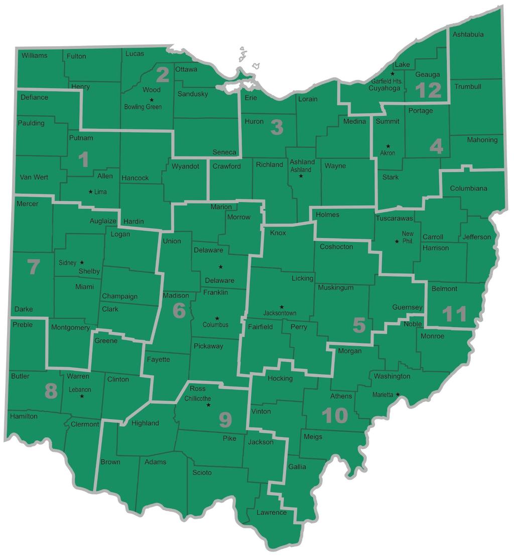
6 BDM SEISMIC PERFORMANCE ZONE 1 All bridges in the State of Ohio are located within Seismic Performance Zone 1. Bridges designed according to the Strength and Service Limit States of the AASHTO LRFD Bridge Design Specifications are assumed to have sufficient capacity to resist Seismic Performance Zone 1 design loads applied at the Extreme Limit State. Seismic analysis is not required except as noted in BDM Sections a and b. 6
7 BDM SEISMIC PERFORMANCE ZONE 1 All bridges in the State of Ohio are located within Seismic Performance Zone 1. Bridges designed according to the Strength and Service Limit States of the AASHTO LRFD Bridge Design Specifications are assumed to have sufficient capacity to resist Seismic Performance Zone 1 design loads applied at the Extreme Limit State. Seismic analysis is not required except as noted in BDM Sections a and b. 7
8 BDM SEISMIC PERFORMANCE ZONE 1 (continued) For bridges located in Site Class D, E and F, Designers shall determine the acceleration coefficient, S D1, according to LFRD Eq with F v = 2.4. For Ohio only areas where S 1 >= and Site Class D, E and F exist, will 0.10 <=S D1 <0.15 (See Figure ). 8
9 BDM SEISMIC PERFORMANCE ZONE 1 (continued) For bridges located in Site Class D, E and F, Designers shall determine the acceleration coefficient, S D1, according to LFRD Eq with F v = 2.4. For Ohio only ares where S 1 >= and Site Class D, E and F exist, will 0.10 <=S D1 <0.15 (See Figure ). 9
10 BDM SEISMIC PERFORMANCE ZONE 1 (continued) For bridges founded at locations with 0.10<=S D1 <0.15, the transverse reinforcement requirements at the top and bottom of columns shall be specified in LRFD d and e. If sufficient geotechnical information is not available to determine Site Class, and the project is located in areas where S 1 >=0.042, then Designers shall assume 0.10<=S D1 <0.15. Otherwise, Designers shall assume S D1 <
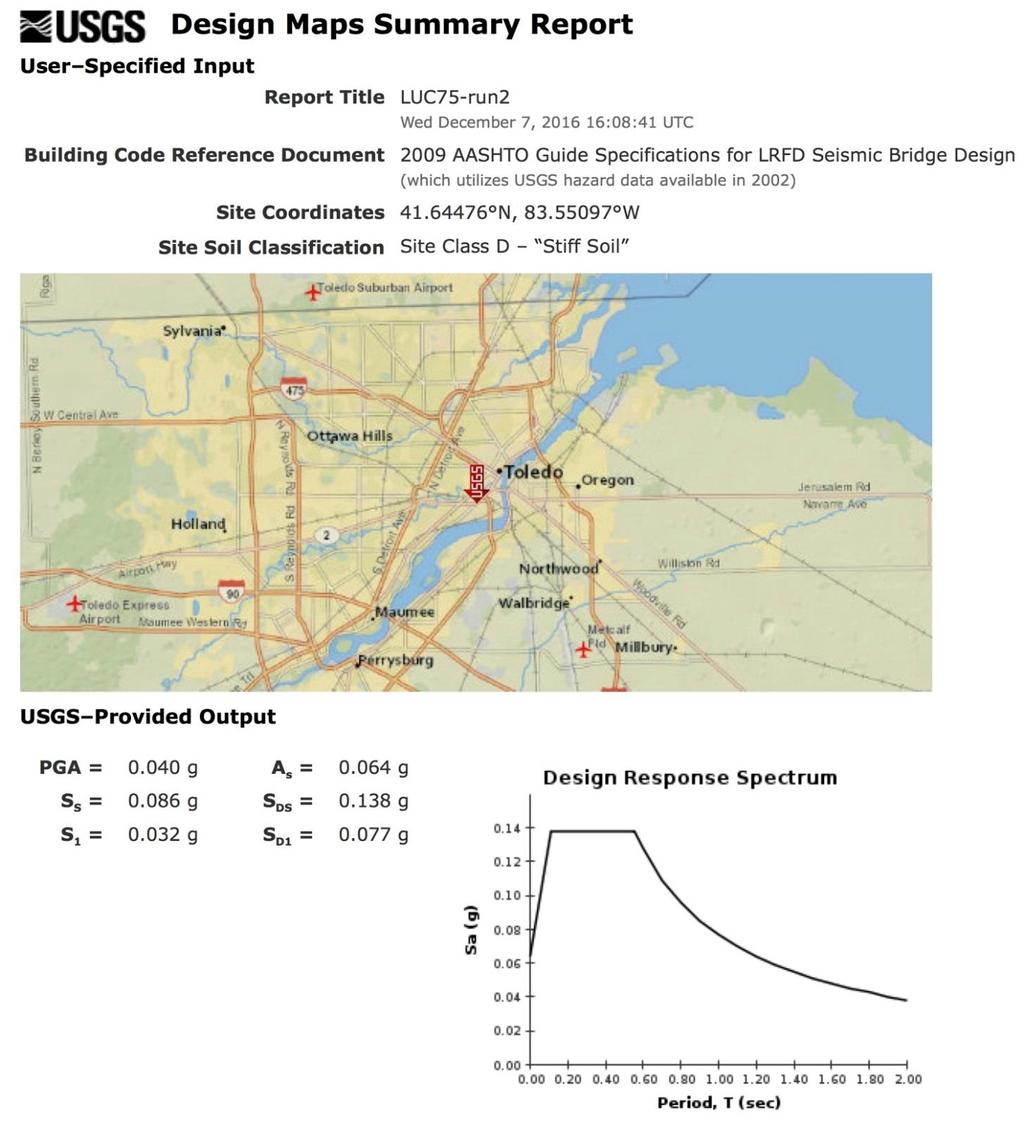
11 BDM SEISMIC PERFORMANCE ZONE 1 (continued) Designers may use the Seismic maps, LRFD Figure or the USGS US Seismic Design Maps web application to determine S 1 and S D a Minimum Support Length Requirements b Substructure. 11
12 BDM Existing Structures Seismic vulnerability of a structure shall be considered for rehabilitation projects requiring complete deck or superstructure replacements. New substructure units shall be designed in accordance with LRFD , and If sufficient geotechnical information is not available, Designers may assume: A. A s > 0.05 B. S D <
13 BDM Existing Structures Seismic vulnerability of a structure shall be considered for rehabilitation projects requiring complete deck or superstructure replacements. New substructure units shall be designed in accordance with LRFD , and If sufficient geotechnical information is not available, Designers may assume: A. A s > 0.05 B. S D <
14 BDM S General Procedure When required by BDM Section to determine the seismologic data for a project location, Designers may use the Seismic maps, LRFD Figure or the USGS US Seismic Design Maps web application using latitude and longitude. BDM S Site Specific Procedure This procedure is not required for Ohio. 14
15 BDM S General Procedure When required by BDM Section to determine the seismologic data for a project location, Designers may use the Seismic maps, LRFD Figure or the USGS US Seismic Design Maps web application using latitude and longitude. BDM S Site Specific Procedure This procedure is not required for Ohio. 15
16 BDM S Site Class Definitions In the absence of sufficient geotechnical information, Designers shall assume Site Class D for the project soil profile. Designer shall use blow counts corrected to an equivalent rod energy ration of 60%, N 60 as defined in the ODOT Specifications for Geotechnical Explorations for the average SPT blow count. 16
17 BDM S Site Class Definitions In the absence of sufficient geotechnical information, Designers shall assume Site Class D for the project soil profile. Designer shall use blow counts corrected to an equivalent rod energy ration of 60%, N 60 as defined in the ODOT Specifications for Geotechnical Explorations for the average SPT blow count. 17
18 BDM S Seismic Performance Zones All bridges in the state of Ohio are located in within Seismic Performance Zone 1. 18
19 Table Seismic Zones Acceleration Seismic Zone Coefficient S D1 S D1 < < S D1 < < S D1 < < S D1 4 ODOT BDM S All bridges in Ohio are located within Seismic Performance Zone 1. 19
20 What information should be provided by the Geotechnical Engineer? In an ideal world.. (actually, WA State) The Geotechnical Designer is responsible for providing geotechnical/seismic parameters to the Structural Engineers for their use in structural design. Specific elements include: Design ground motion parameters Site Response Input for evaluation of soil-structure interaction (foundation response to seismic loading), earthquake induced earth pressures on retaining walls 20
21 In the real world Designer: What s the Site Class? Geotechnical Engineer: C Designer: Thank-You 21

22 BACKGROUND We need to understand how seismically induced ground motion is transmitted to structural components. Washington Cathedral Virginia Event

23 Epicenter Distance Seismic Performance Zone (1-4) Design Response Spectrum Structure of Interest Fault Rupture (Epicenter) Energy Propagation In Soil Site Class A-E Earthquake Magnitude M Energy Propagation In Rock as ground motion USGS derives MCE Maximum Considered Earthquake M7.7 NMSZ 2% Probability in 50 yrs ( 1 in 2500 yrs) PGA Peak Ground Acceleration And Response Spectrum 7% Probability in 75 yrs (1in 1000 yrs) 23
24 Seismic Hazard How do we define or describe a seismic hazard? Earthquake magnitude? Earthquakes are always classified on a logarithmic scale, usually 1 10, so that 7.0 is 100 times stronger than 5.0 and 8.0 is 1000 times stronger than

25 Distance to Epicenter (500 miles is better for your structure than 5 miles) 25
26 Site Conditions Can have a significant local effect by amplifying ground motion Frequency of Occurrence -Infrequent is best! 26
27 Ohio is on the fringe of the New Madrid Seismic Zone. We get the left-overs from any event that occurs on that system. Leftovers can be a problem - Cincinnati experienced some damage in the 1811/12 event. 27

28 Home Grown Ohio Earthquakes New Madrid Seismic Zone 28
29 29
30 3030
31 Anna Area 31
 extraction in this area.")
32 Note a correlation with the period of peak hydrocarbon (gas and crude oil) extraction in this area. Northwest Ohio
33 Lake and Ashtabula counties Note the correlation with operations of a deep well injection system from mid-1980 s to early 2000 s in this area. 33
34 Here s the Youngstown Area Note correlation with recent fracking and deep well disposal operations post
35 Which is more critical? A magnitude 8.0 earthquake on the New Madrid Fault 500 miles away or a magnitude 5.4 earthquake on an unknown fault in northeast Ohio 3 miles from your new bridge? 35
36 Cornell's Method (1979) Ln A p = * M l * ln (R +25) A p = Peak Ground Acceleration (cm/s 2 ) M l = Magnitude R = distance (km) Note: 289 GMPE equations published for PGA. 36
37 37
 Convert this to something that can be useful for design Develop a Design Response Spectrum")
38 acceleration factor (xg) METHODOLOGY Spectral Acceleration What is it? Raw Accelerograph Record t (seconds) Convert this to something that can be useful for design Develop a Design Response Spectrum Displays Maximum Acceleration for a range of ground motion periods 38
39 Construction of the Design Spectrum Input: S s PGA Peak Ground Acceleration S s short period Spectral Acceleration S 1 long-period Spectral Acceleration Apply Site Specific Factors PGA S 1 39
40 Site Class A B C D E Soil Profile Name Soil Shear Wave Velocity Average Properties in Top 100 ft Standard Penetration Resistance Soil Undrained Shear Strength E may, together with F, be a special case very weak soils. 40
41 Site Class Soil Profile Name Soil Shear Wave Velocity, v s, (ft/s) A Hard rock v s > 5,000 B Rock 2,500 < v s < 5,000 C Very dense soil and soft rock 1,200 < v s < 2,500 D Stiff Soil Profile 600 < v s < 1,200 E Soft Soil Profile v s < 600 Difficult to measure Can use seismic CPT, seismic refraction or published values, with caution. 41
42 Soil/Rock Type P Wave ft/s S Wave ft/s Site Class Scree, vegetal soil D/E Dry sands C/D/E Wet sands C Saturated shales and clays B/C/D Marls B Saturated shale and sand sections Porous and saturated sandstones B/C A/B Limestones A Dolomite A Coal B Classification Criteria and below 600 E D C B 5000 and above A 42
43 Site Class Soil Profile Name Standard Penetration penetration Resistance, N N A Hard rock NA B Rock NA C Very dense soil and soft rock N > 50 D Stiff Soil Profile 15 < N < 50 E Soft Soil Profile N < 15 43
44 Site Class Soil Profile Name Soil Undrained Shear Strength, s u, (psf) A Hard rock NA B Rock NA C Very dense soil and soft rock s u > 2,000 D Stiff Soil Profile 1,000 < s u < 2,000 E Soft Soil Profile s u < 1,000 44


45 Site Class Soil Profile Name Soil Shear Wave Velocity Standard Penetration Resistance Soil Undrained Shear Strength Any profile with more than 10 ft of soil having the following characteristics: E - 1. Plasticity index PI > 20, 2. Moisture Content w > 40%, and 3. Undrained shear strength s u < 500 psf 45

46 Site Class Soil Profile Name Soil Shear Wave Velocity Standard Penetration Resistance Soil Undrained Shear Strength Any profile containing soils having one or more of the following characteristics: F - 1. Soils vulnerable to potential failure or collapse under seismic loading such as liquefiable soils, quick and highly sensitive clays, collapsible weakly cemented soils. 2. Peats and/or highly organic clays (H > 10 ft of peat and/or highly organic clay where H = thickness of soil) 3. Very high plasticity clays (H > 25 ft with plasticity index PI > Very thick soft/medium stiff clays (H > 120 ft) 46

47 Site Class PGA 1 < >0.50 S 1 s < >1.25 A B C D E F Use straight-line interpolation for intermediate values. Site-specific geotechnical investigation and dynamic site response analysis should be performed for all sites in Site Class F. Tables and

48 Site Class Spectral Acceleration Coefficient At Period 1.0 sec (S 1 ) 1 < A B C D E F Use straight-line interpolation for intermediate values. Site-specific geotechnical investigation and dynamic site response analysis should be performed for all sites in Site Class F. 48
 the value of F v and F a need not be taken larger than 2.4 and 1.6, respectively, when S 1 is less than or equal to 0.")
49 (1) For the purpose of determining the Seismic Hazard Level for Site Class E Soils (Article ) the value of F v and F a need not be taken larger than 2.4 and 1.6, respectively, when S 1 is less than or equal to 0.10 and S s is less than
50 (2) For the purposes of determining the Seismic Hazard Level for Site Class F Soils (Article ) F v and F a values for Site Class E soils may be used with the adjustment described in Note 1 above. 50

. 51")
51 Site PGA 1 < >0.50 Class S 1 s < >1.25 A B C D E F Use straight-line interpolation for intermediate values. ODOT BDM use site factors for Site Class D for Site Class E and F (S ). 51
52 Spectral Acceleration Coefficient Site At Period 1.0 sec (S 1 ) 1 Class < A B C D E F Use straight-line interpolation for intermediate values. ODOT BDM use site factors for Site Class D for Site Class E and F (S ). 52
53 METHODOLOGY Construction of Design Response Spectrum Using LRFD Figures through -21 PGA = 0.3s S s = 0.5s S 1 = 0.2s Site Class = C 53
54 Elastic Seismic Coefficient (C sm ) (g) A s S DS 1. A s = F pga * PGA e.g. 1.1 * 0.3 = 0.33 PGA - peak ground acceleration - rock - Site Class B F pga - Site factor at zero period 2. S DS = F a * S s e.g. 1.2 * 0.5 = 0.60 F a - Site Factor - short period range S s - Short period acceleration (0.2 sec) 3. S D1 = F v * S 1 e.g. 1.6 * 0.2 = 0.32 F v - Site Factor - long period range S 1 - Short period acceleration (1.0 sec) S D1 4. T s = S D1 /S DS e.g / 0.60 = 0.53 T s = corner period 5. T o = 0.2*T s e.g. 0.2 * 0.53= T o = reference period Construction of Design Response Spectrum T o Period, T m (sec) T s 54
55 55
56 56
57 Ground Motion (PGA, S s, S 1 ) + Site Classification (A-F) + Site Factors (F pga, F s, F v ) Design Response Spectrum Seismic Zone Determination (1-4) 57
58 BDM Fig S D1 = S 1 * F V if S D1 > 0.10 and F v = 2.4 S 1 > 0.10/2.4 = (4.2%g) 58


 YES NO BDM 301.4.4.2a YES OR UNKNOWN Is 0.")
59 All bridges in Ohio are in Seismic Performance Zone 1 S D1 <= 0.15 Determine Site Class designer shall analyze soil borings.. LRFD Is Site Class A, B or C? NO YES Consider only BDM a BDM b YES Is Site Class F? Consider BDM a, b LRFD d, e NO Is S 1 >=0.042? (Fig ) YES NO BDM a YES OR UNKNOWN Is 0.1<S D1 <0.15? (use F v =2.4) NO 59
60 WORKED EXAMPLES 60

61 EXAMPLE 1 Site Classification Lucas Bridge Depth N 60 B-093 B
62 Summary by Layer i N i from to d i d i /N i Σ d i /N i 9.89 Σ d i 100 Class Σ d i /Σd i /Ave N i 10 E Note: N i should be based on the N60 not raw N values (BDM S ). Lucas Bridge

63 Lucas Bridge Depth s u B-093 B
64 Summary by Layer i su i from to d i d i /su i Σ d i /su i Σ d i 100 Class Σ d i /Σd i /su i Ave su i 1.22 D Note: For Cohesive soils, S u is more reliable than N. Lucas Bridge
65 Lucas Bridge Design Response Spectrum 65

66 EXAMPLE 2 Fairfield County, Ohio 66
67 Forward Abutment Rock (Sandstone) 2600 < V s < 5900 ft/s B S D1 = Rear Abutment 50 ft embankment + overburden 50 ft rock (sandstone) i V si from to d i d i /su i Σd i 100 Class Σd i /Σd i /su i S D1 = Ave su i 833 D Σd i /su i 0.12 Fairfield County, Ohio 67
68 EXAMPLE 3 Mill Creek Crossing Abutment Rock (Shale) V s = 1700 ft/s Soil Class C Piers soft clay Soil Class E (AASHTO) Soil Class D (ODOT) Soil Class S D1 C (<0.1) D (>0.1) (SPZ 1-BDM) E (SPZ 2 AASHTO) HAM-Western Hills Viaduct 68
Improvements to the Development of Acceleration Design Response Spectra. Nicholas E. Harman, M.S., P.E., SCDOT
 Improvements to the Development of Acceleration Design Response Spectra Nicholas E. Harman, M.S., P.E., SCDOT Thanks Clemson University Dr. Ron Andrus Co-Principal Investigator Dr. Nadarajah Ravichandran
PROPOSED CHANGE TO THE 2012 BUILDING CODE O. REG. 332/12 AS AMENDED
 Ministry of Municipal Affairs PROPOSED CHANGE TO THE 2012 BUILDING CODE O. REG. 332/12 AS AMENDED CHANGE NUMBER: SOURCE: B-04-01-15 Ontario-NBC CODE REFERENCE: Division B / 4.1.8.2. Division B / 4.1.8.4.
Chapter 12 Subsurface Exploration
 Page 12 1 Chapter 12 Subsurface Exploration 1. The process of identifying the layers of deposits that underlie a proposed structure and their physical characteristics is generally referred to as (a) subsurface
Harmonized European standards for construction in Egypt
 Harmonized European standards for construction in Egypt EN 1998 - Design of structures for earthquake resistance Jean-Armand Calgaro Chairman of CEN/TC250 Organised with the support of the Egyptian Organization
Date: April 2, 2014 Project No.: Prepared For: Mr. Adam Kates CLASSIC COMMUNITIES 1068 E. Meadow Circle Palo Alto, California 94303
 City of Newark - 36120 Ruschin Drive Project Draft Initial Study/Mitigated Negative Declaration Appendix C: Geologic Information FirstCarbon Solutions H:\Client (PN-JN)\4554\45540001\ISMND\45540001 36120
An Overview of Geotechnical Earthquake Engineering
 An Overview of Geotechnical Earthquake Engineering Sudhir K Jain Slide 1 Outline Introduction to Seismic Design Principle Dynamic Soil Properties Site Effects Soil Structure Interaction Issues for Foundation
Chapter 6 Seismic Design of Bridges. Kazuhiko Kawashima Tokyo Institute of Technology
 Chapter 6 Seismic Design of Bridges Kazuhiko Kawashima okyo Institute of echnology Seismic Design Loading environment (dead, live, wind, earthquake etc) Performance criteria for gravity (deflection, stresses)
SEISMIC HAZARD ANALYSIS. Instructional Material Complementing FEMA 451, Design Examples Seismic Hazard Analysis 5a - 1
 SEISMIC HAZARD ANALYSIS Instructional Material Complementing FEMA 451, Design Examples Seismic Hazard Analysis 5a - 1 Seismic Hazard Analysis Deterministic procedures Probabilistic procedures USGS hazard
Liquefaction and Foundations
 Liquefaction and Foundations Amit Prashant Indian Institute of Technology Gandhinagar Short Course on Seismic Design of Reinforced Concrete Buildings 26 30 November, 2012 What is Liquefaction? Liquefaction
Overview of National Seismic Hazard Maps for the next National Building Code
 Overview of National Seismic Hazard Maps for the next National Building Code John Adams Earthquakes Canada Geological Survey of Canada Copyright. Her Majesty the Queen in Right of Canada, 2004 CSCE Workshop
Evaluating the Seismic Coefficient for Slope Stability Analyses
 Evaluating the Seismic Coefficient for Slope Stability Analyses by Edward Kavazanjian, Jr., Ph.D., P.E.,D.GE., NAE Ira A. Fulton Professor of Geotechnical Engineering School of Sustainable Engineering
Boreholes. Implementation. Boring. Boreholes may be excavated by one of these methods: 1. Auger Boring 2. Wash Boring 3.
 Implementation Boreholes 1. Auger Boring 2. Wash Boring 3. Rotary Drilling Boring Boreholes may be excavated by one of these methods: 4. Percussion Drilling The right choice of method depends on: Ground
Development of U. S. National Seismic Hazard Maps and Implementation in the International Building Code
 Development of U. S. National Seismic Hazard Maps and Implementation in the International Building Code Mark D. Petersen (U.S. Geological Survey) http://earthquake.usgs.gov/hazmaps/ Seismic hazard analysis
Effective stress analysis of pile foundations in liquefiable soil
 Effective stress analysis of pile foundations in liquefiable soil H. J. Bowen, M. Cubrinovski University of Canterbury, Christchurch, New Zealand. M. E. Jacka Tonkin and Taylor Ltd., Christchurch, New
GEOTECHNICAL SITE CHARACTERIZATION
 GEOTECHNICAL SITE CHARACTERIZATION Neil Anderson, Ph.D. Professor of Geology and Geophysics Richard W. Stephenson, P.E., Ph.D. Professor of Civil, Architectural and Environmental Engineering University
AGMU Memo Liquefaction Analysis
 LRFD Liquefaction Analysis This design guide illustrates the Department s recommended procedures for analyzing the liquefaction potential of soil during a seismic event considering Article 0.5.4.2 of the
Micro Seismic Hazard Analysis
 Micro Seismic Hazard Analysis Mark van der Meijde INTERNATIONAL INSTITUTE FOR GEO-INFORMATION SCIENCE AND EARTH OBSERVATION Overview Site effects Soft ground effect Topographic effect Liquefaction Methods
Seismic Stability of Tailings Dams, an Overview
 Seismic Stability of Tailings Dams, an Overview BY Gonzalo Castro, Ph.D., P.E. Principal International Workshop on Seismic Stability of Tailings Dams Case Western Reserve University, November 2003 Small
LRFD GEOTECHNICAL IMPLEMENTATION
 LRFD GEOTECHNICAL IMPLEMENTATION Ching-Nien Tsai, P.E. LADOTD Pavement and Geotechnical Services In Conjunction with LTRC WHY LRFD FHWA deadline - October 2007 LRFD is a better method Risk is quantified
CHAPTER 3 METHODOLOGY
 32 CHAPTER 3 METHODOLOGY 3.1 GENERAL In 1910, the seismological society of America identified the three groups of earthquake problems, the associated ground motions and the effect on structures. Indeed
Earthquake Loads According to IBC IBC Safety Concept
 Earthquake Loads According to IBC 2003 The process of determining earthquake loads according to IBC 2003 Spectral Design Method can be broken down into the following basic steps: Determination of the maimum
Table 3. Empirical Coefficients for BS 8002 equation. A (degrees) Rounded Sub-angular. 2 Angular. B (degrees) Uniform Moderate grading.
 Rounded Sub-angular. 2 Angular. B (degrees) Uniform Moderate grading.") Hatanaka and Uchida (1996); ' 20N 20 12N 20 ' 45 A lower bound for the above equation is given as; 12N 15 ' 45 Table 3. Empirical Coefficients for BS 8002 equation A Angularity 1) A (degrees) Rounded 0
Hatanaka and Uchida (1996); ' 20N 20 12N 20 ' 45 A lower bound for the above equation is given as; 12N 15 ' 45 Table 3. Empirical Coefficients for BS 8002 equation A Angularity 1) A (degrees) Rounded 0
Seismic Evaluation of Tailing Storage Facility
 Australian Earthquake Engineering Society 2010 Conference, Perth, Western Australia Seismic Evaluation of Tailing Storage Facility Jonathan Z. Liang 1, David Elias 2 1 Senior Geotechnical Engineer, GHD
What will a Magnitude 6.0 to 6.8 Earthquake do to the St. Louis Metro Area?
 What will a Magnitude 6.0 to 6.8 Earthquake do to the St. Louis Metro Area? J. David Rogers Natural Hazards Mitigation Center University of Missouri-Rolla USGS Mid-Continent Geographic Science Center Missouri
LIQUEFACTION OF EARTH EMBANKMENT DAMS TWO CASE HISTORIES: (1) LIQUEFACTION OF THE EMBANKMENT SOILS, AND (2) LIQUEFACTION OF THE FOUNDATIONS SOILS
 LIQUEFACTION OF THE EMBANKMENT SOILS, AND (2) LIQUEFACTION OF THE FOUNDATIONS SOILS") LIQUEFACTION OF EARTH EMBANKMENT DAMS TWO CASE HISTORIES: (1) LIQUEFACTION OF THE EMBANKMENT SOILS, AND (2) LIQUEFACTION OF THE FOUNDATIONS SOILS Antonio Fernandez, Ph.D. 1 ABSTRACT Paul C. Rizzo Associates,
LIQUEFACTION OF EARTH EMBANKMENT DAMS TWO CASE HISTORIES: (1) LIQUEFACTION OF THE EMBANKMENT SOILS, AND (2) LIQUEFACTION OF THE FOUNDATIONS SOILS Antonio Fernandez, Ph.D. 1 ABSTRACT Paul C. Rizzo Associates,
Minnesota Department of Transportation Geotechnical Section Cone Penetration Test Index Sheet 1.0 (CPT 1.0)
") This Cone Penetration Test (CPT) Sounding follows ASTM D 778 and was made by ordinary and conventional methods and with care deemed adequate for the Department's design purposes. Since this sounding was
This Cone Penetration Test (CPT) Sounding follows ASTM D 778 and was made by ordinary and conventional methods and with care deemed adequate for the Department's design purposes. Since this sounding was
INTRODUCTION TO STATIC ANALYSIS PDPI 2013
 INTRODUCTION TO STATIC ANALYSIS PDPI 2013 What is Pile Capacity? When we load a pile until IT Fails what is IT Strength Considerations Two Failure Modes 1. Pile structural failure controlled by allowable
Geotechnical Engineering Report
 Geotechnical Engineering Report Turner Turnpike Widening Bridge B Bridge Crossing: South 257 th West Avenue Creek County, Oklahoma June 1, 2016 Terracon Project No. 04155197 Prepared for: Garver, LLC Tulsa,
IZMIT BAY BRIDGE SOUTH APPROACH VIADUCT: SEISMIC DESIGN NEXT TO THE NORTH ANATOLIAN FAULT
 Istanbul Bridge Conference August 11-13, 2014 Istanbul, Turkey IZMIT BAY BRIDGE SOUTH APPROACH VIADUCT: SEISMIC DESIGN NEXT TO THE NORTH ANATOLIAN FAULT A. Giannakou 1, J. Chacko 2 and W. Chen 3 ABSTRACT
Evaluation of Geotechnical Hazards
 Evaluation of Geotechnical Hazards by Geoffrey R. Martin Appendix B: Evaluation of Geotechnical Hazards Describes Evaluation Procedures Soil Liquefaction Soil Settlement Surface Fault Rupture Flooding
IN SITU TESTING TECHNOLOGY FOR FOUNDATION & EARTHQUAKE ENGINEERING. Wesley Spang, Ph.D., P.E. AGRA Earth & Environmental, Inc.
 IN SITU TESTING TECHNOLOGY FOR FOUNDATION & EARTHQUAKE ENGINEERING Wesley Spang, Ph.D., P.E. AGRA Earth & Environmental, Inc. Portland, Oregon In situ testing of soil, which essentially consists of evaluating
B-1 BORE LOCATION PLAN. EXHIBIT Drawn By: 115G BROOKS VETERINARY CLINIC CITY BASE LANDING AND GOLIAD ROAD SAN ANTONIO, TEXAS.
 N B-1 SYMBOLS: Exploratory Boring Location Project Mngr: BORE LOCATION PLAN Project No. GK EXHIBIT Drawn By: 115G1063.02 GK Scale: Checked By: 1045 Central Parkway North, Suite 103 San Antonio, Texas 78232
New Ground Motion Requirements of ASCE 7-16
 New Ground Motion Requirements of ASCE 7-16 Building EERI Seismic Seminar on Safety Next Generation Council Webinar Attenuation Models July 28, 2017 Charlie Kircher Kircher & Associates Palo Alto, California
UChile - LMMG Shear Wave Velocity (V S. ): Measurement, Uncertainty, and Utility in Seismic Hazard Analysis. Robb Eric S. Moss, Ph.D., P.E.
: Measurement, Uncertainty, and Utility in Seismic Hazard Analysis. Robb Eric S. Moss, Ph.D., P.E.") UChile - LMMG 2015 Shear Wave Velocity (V S ): Measurement, Uncertainty, and Utility in Seismic Hazard Analysis Robb Eric S. Moss, Ph.D., P.E. Assoc. Prof. of Earthquake, Geotechnical, and Risk Engineering
UChile - LMMG 2015 Shear Wave Velocity (V S ): Measurement, Uncertainty, and Utility in Seismic Hazard Analysis Robb Eric S. Moss, Ph.D., P.E. Assoc. Prof. of Earthquake, Geotechnical, and Risk Engineering
Class Principles of Foundation Engineering CEE430/530
 Class Principles of Foundation Engineering CEE430/530 1-1 General Information Lecturer: Scott A. Barnhill, P.E. Lecture Time: Thursday, 7:10 pm to 9:50 pm Classroom: Kaufmann, Room 224 Office Hour: I have
Y. Shioi 1, Y. Hashizume 2 and H. Fukada 3
 Y. Shioi 1, Y. Hashizume 2 and H. Fukada 3 1 Emeritus Professor, Hachinohe Institute of Technology, Hachinohe, Japan 2 Chief Engineer, Izumo, Misawa, Aomori, Japan 3 Profesr, Geo-Technical Division, Fudo
Unique Site Conditions and Response Analysis Challenges in the Central and Eastern U.S.
 Unique Site Conditions and Response Analysis Challenges in the Central and Eastern U.S. James R. Martin, C. Guney Olgun, & Morgan Eddy Civil and Environmental Engineering World Institute for Disaster Risk
Chapter (11) Pile Foundations
 Pile Foundations") Chapter (11) Introduction Piles are structural members that are made of steel, concrete, or timber. They are used to build pile foundations (classified as deep foundations) which cost more than shallow
Chapter (11) Introduction Piles are structural members that are made of steel, concrete, or timber. They are used to build pile foundations (classified as deep foundations) which cost more than shallow
Chapter 7 GEOMECHANICS
 Chapter 7 Final SCDOT GEOTECHNICAL DESIGN MANUAL August 2008 Table of Contents Section Page 7.1 Introduction...7-1 7.2 Geotechnical Design Approach...7-1 7.3 Geotechnical Engineering Quality Assurance...7-2
SEISMIC CODE ISSUES IN CENTRAL UNITED STATES
 13 th World Conference on Earthquake Engineering Vancouver, B.C., Canada August 1-6, 2004 Paper No. 1843 SEISMIC CODE ISSUES IN CENTRAL UNITED STATES SHAHRAM PEZESHK 1 SUMMARY The Applied Technology Council
Dr. P. Anbazhagan 1 of 61
 Module 10: Seismic site classification Topics Introduction to seismic Site Characterization, Site characterization data Need for Site Characterization Grids for Site characterization Interpolation of non-filled
Evaluation of the Liquefaction Potential by In-situ Tests and Laboratory Experiments In Complex Geological Conditions
 Evaluation of the Liquefaction Potential by In-situ Tests and Laboratory Experiments In Complex Geological Conditions V. Sesov, K. Edip & J. Cvetanovska University Ss. Cyril and Methodius, Institute of
Earth Mechanics, Inc. Geotechnical & Earthquake Engineering
 TECHNICAL MEMORANDUM EMI PROJECT NO: 13-116 DATE: October 29, 2013 PREPARED FOR: Mr. Todd W. Dudley / AECOM PREPARED BY: SUBJECT: (Raja) S. Pirathiviraj and Lino Cheang / (EMI) Preliminary Foundation Report
Geotechnical Engineering Report
 Geotechnical Engineering Report Turner Turnpike Widening Bridge D Bridge Crossing: South 209 th West Avenue Creek County, Oklahoma June 1, 2016 Terracon Project No. 04155197 Prepared for: Garver, LLC Tulsa,
The process of determining the layers of natural soil deposits that will underlie a proposed structure and their physical properties is generally
 The process of determining the layers of natural soil deposits that will underlie a proposed structure and their physical properties is generally referred to as sub surface investigation 2 1 For proper
Soil Behaviour in Earthquake Geotechnics
 Soil Behaviour in Earthquake Geotechnics KENJI ISHIHARA Department of Civil Engineering Science University of Tokyo This publication was supported by a generous donation from the Daido Life Foundation
Background. Valley fills Sites in the Area. Construction over Mine Spoil Fills
 Construction over Mine Spoil Fills Wayne A. Karem, PhD, PE, PG, D.GE 2014 KSPE Annual Conference Background Strip mining; mountaintop and contour mining Creates huge quantities of mine spoil The mine spoil
Probabilistic damage control seismic design of bridges using structural reliability concept
 Probabilistic damage control seismic design of bridges using structural reliability concept A. Saini Doctoral Student, University of Nevada, Reno, NV, USA A. Vosooghi Bridge Engineer III, Ph.D., P.E.,
Synthetic Near-Field Rock Motions in the New Madrid Seismic Zone
 Synthetic Near-Field Rock Motions in the New Madrid Seismic Zone Genda Chen*, Ph.D., P.E., and Mostafa El-Engebawy Engebawy,, Ph.D. *Associate Professor of Civil Engineering Department of Civil, Architecture
The Bearing Capacity of Soils. Dr Omar Al Hattamleh
 The Bearing Capacity of Soils Dr Omar Al Hattamleh Example of Bearing Capacity Failure Omar Play the move of bearing Capacity failure The Philippine one Transcona Grain Silos Failure - Canada The Bearing
PRINCIPLES OF GEOTECHNICAL ENGINEERING
 PRINCIPLES OF GEOTECHNICAL ENGINEERING Fourth Edition BRAJA M. DAS California State University, Sacramento I(T)P Boston Albany Bonn Cincinnati London Madrid Melbourne Mexico City New York Paris San Francisco
The Role of Local Site Conditions in The Seismic Assessment of Historical Monuments
 The Role of Local Site Conditions in The Seismic Assessment of Historical Monuments J. Cvetanovska, V. Sesov, I. Gjorgiev & K. Edip Univeristy Ss. Cyril and Methodius, Institute of Earthquake Engineering
Seismic design of bridges
 NATIONAL TECHNICAL UNIVERSITY OF ATHENS LABORATORY FOR EARTHQUAKE ENGINEERING Seismic design of bridges Lecture 3 Ioannis N. Psycharis Capacity design Purpose To design structures of ductile behaviour
Geotechnical Modeling Issues
 Nonlinear Analysis of Viaducts and Overpasses Geotechnical Modeling Issues Steve Kramer Pedro Arduino Hyung-Suk Shin University of Washington The Problem Approach Soil Soil Soil Soil Soil Soil Soil Soil
Reinforced Soil Structures Reinforced Soil Walls. Prof K. Rajagopal Department of Civil Engineering IIT Madras, Chennai
 Geosynthetics and Reinforced Soil Structures Reinforced Soil Walls continued Prof K. Rajagopal Department of Civil Engineering IIT Madras, Chennai e-mail: gopalkr@iitm.ac.inac in Outline of the Lecture
KDOT Geotechnical Manual Edition. Table of Contents
 KDOT Geotechnical Manual 2007 Edition The KDOT Geotechnical Manual is available two volumes. Both volumes are very large electronic (pdf) files which may take several minutes to download. The table of
14 Geotechnical Hazards
 Volume 2: Assessment of Environmental Effects 296 14 Geotechnical Hazards Overview This Chapter provides an assessment of the underlying geotechnical conditions to identify: any potential liquefaction
SOME OBSERVATIONS RELATED TO LIQUEFACTION SUSCEPTIBILITY OF SILTY SOILS
 SOME OBSERVATIONS RELATED TO LIQUEFACTION SUSCEPTIBILITY OF SILTY SOILS Upul ATUKORALA 1, Dharma WIJEWICKREME 2 And Norman MCCAMMON 3 SUMMARY The liquefaction susceptibility of silty soils has not received
Minnesota Department of Transportation Geotechnical Section Cone Penetration Test Index Sheet 1.0 (CPT 1.0)
") This Cone Penetration Test (CPT) Sounding follows ASTM D 5778 and was made by ordinary and conventional methods and with care deemed adequate for the Department's design purposes. Since this sounding was
This Cone Penetration Test (CPT) Sounding follows ASTM D 5778 and was made by ordinary and conventional methods and with care deemed adequate for the Department's design purposes. Since this sounding was
Chapter 3. Geotechnical Design Considerations
 Chapter 3 Geotechnical Design Considerations Marshall Lew, Ph.D., G.E. Corporate Consultant, Law/Crandall, a division of Law Engineering and Environmental Services, Inc. (A LAWGIBB Group Member), Los Angeles
ENGINEER S CERTIFICATION OF FAULT AREA DEMONSTRATION (40 CFR )
") PLATTE RIVER POWER AUTHORITY RAWHIDE ENERGY STATION BOTTOM ASH TRANSFER (BAT) IMPOUNDMENTS LARIMER COUNTY, CO ENGINEER S CERTIFICATION OF FAULT AREA DEMONSTRATION (40 CFR 257.62) FOR COAL COMBUSTION RESIDUALS
PLATTE RIVER POWER AUTHORITY RAWHIDE ENERGY STATION BOTTOM ASH TRANSFER (BAT) IMPOUNDMENTS LARIMER COUNTY, CO ENGINEER S CERTIFICATION OF FAULT AREA DEMONSTRATION (40 CFR 257.62) FOR COAL COMBUSTION RESIDUALS
Should you have any questions regarding this clarification, please contact the undersigned at or (925)
") October 8, 2015 Revised October 13, 2015 Contra Costa Community College District 500 Court Street Martinez, CA 94553 Attention: Ron Johnson Subject: Clarification of Grading Requirements Diablo Valley
October 8, 2015 Revised October 13, 2015 Contra Costa Community College District 500 Court Street Martinez, CA 94553 Attention: Ron Johnson Subject: Clarification of Grading Requirements Diablo Valley
Section Forces Within Earth. 8 th Grade Earth & Space Science - Class Notes
 Section 19.1 - Forces Within Earth 8 th Grade Earth & Space Science - Class Notes Stress and Strain Stress - is the total force acting on crustal rocks per unit of area (cause) Strain deformation of materials
IV. ENVIRONMENTAL IMPACT ANALYSIS G. GEOLOGY AND SOILS
 IV. ENVIRONMENTAL IMPACT ANALYSIS G. GEOLOGY AND SOILS The following section is a summary of the geotechnical report conducted for the proposed project. The Report of Geotechnical Investigation Proposed
Important Concepts. Earthquake hazards can be categorized as:
 Lecture 1 Page 1 Important Concepts Monday, August 17, 2009 1:05 PM Earthquake Engineering is a branch of Civil Engineering that requires expertise in geology, seismology, civil engineering and risk assessment.
This document downloaded from vulcanhammer.net vulcanhammer.info Chet Aero Marine
 This document downloaded from vulcanhammer.net vulcanhammer.info Chet Aero Marine Don t forget to visit our companion site http://www.vulcanhammer.org Use subject to the terms and conditions of the respective
8.1. What is meant by the shear strength of soils? Solution 8.1 Shear strength of a soil is its internal resistance to shearing stresses.
 8.1. What is meant by the shear strength of soils? Solution 8.1 Shear strength of a soil is its internal resistance to shearing stresses. 8.2. Some soils show a peak shear strength. Why and what type(s)
Geology 229 Engineering Geology Lecture 27. Earthquake Engineering (Reference West, Ch. 18)
") Geology 229 Engineering Geology Lecture 27 Earthquake Engineering (Reference West, Ch. 18) Earthquake Engineering 1. General introduction of earthquakes 2. Seismic Hazards 3. Strong ground motion Exactly
Geology 229 Engineering Geology Lecture 27 Earthquake Engineering (Reference West, Ch. 18) Earthquake Engineering 1. General introduction of earthquakes 2. Seismic Hazards 3. Strong ground motion Exactly
EUROCODE EN SEISMIC DESIGN OF BRIDGES
 Brussels, 18-20 February 2008 Dissemination of information workshop 1 EUROCODE EN1998-2 SEISMIC DESIGN OF BRIDGES Basil Kolias Basic Requirements Brussels, 18-20 February 2008 Dissemination of information
Geotechnical Engineering Report
 Geotechnical Engineering Report Turner Turnpike Widening Polecat Creek Bridge (Bridge A) June 1, 2016 Terracon Project No. 04155197 Prepared for: Garver, LLC Prepared by: Terracon Consultants, Inc. TABLE
Geotechnical Site Classification and Croatian National Annex for EC 8
 Geotechnical Site Classification and Croatian National Annex for EC 8 by Predrag Kvasnika University of Zagreb Faculty of Mining-Geology and Petroleum engineering Outline General Motivation Site classification
GNS Science, Lower Hutt, New Zealand NZSEE Conference
 A Ground Shaking Amplification Map for New Zealand U. Destegul, G. Dellow & D. Heron GNS Science, Lower Hutt, New Zealand. 2008 NZSEE Conference ABSTRACT: A ground shaking amplification map of New Zealand
Vertical to Horizontal (V/H) Ratios for Large Megathrust Subduction Zone Earthquakes
 Ratios for Large Megathrust Subduction Zone Earthquakes") Vertical to Horizontal (V/H) Ratios for Large Megathrust Subduction Zone Earthquakes N.J. Gregor Consultant, Oakland, California, USA N.A. Abrahamson University of California, Berkeley, USA K.O. Addo BC
Vertical to Horizontal (V/H) Ratios for Large Megathrust Subduction Zone Earthquakes N.J. Gregor Consultant, Oakland, California, USA N.A. Abrahamson University of California, Berkeley, USA K.O. Addo BC
Soil Mechanics Brief Review. Presented by: Gary L. Seider, P.E.
 Soil Mechanics Brief Review Presented by: Gary L. Seider, P.E. 1 BASIC ROCK TYPES Igneous Rock (e.g. granite, basalt) Rock formed in place by cooling from magma Generally very stiff/strong and often abrasive
TRANSPORTATION RESEARCH BOARD. TRB Webinar Program Direct Displacement Based Seismic Design of Bridges. Thursday, June 22, :00-3:30 PM ET
 TRANSPORTATION RESEARCH BOARD TRB Webinar Program Direct Displacement Based Seismic Design of Bridges Thursday, June 22, 2017 2:00-3:30 PM ET The Transportation Research Board has met the standards and
Remediation of Soft Clay Utilizing the Dry Mix Method. of Batavia, New York to its discharge into the Niagara River at Tonawanda, New York.
 Introduction Tonawanda Creek meanders as it flows in a generally westerly direction from its headwaters east of Batavia, New York to its discharge into the Niagara River at Tonawanda, New York. The geologic
Drilled Shafts for Bridge Foundation Stability Improvement Ohio 833 Bridge over the Ohio River An Update
 Drilled Shafts for Bridge Foundation Stability Improvement Ohio 833 Bridge over the Ohio River An Update Meigs County, Ohio Mason County, West Virginia By Stan Harris, P.E. and Eric Kistner, P.E. FMSM
Geophysical Site Investigation (Seismic methods) Amit Prashant Indian Institute of Technology Gandhinagar
 Amit Prashant Indian Institute of Technology Gandhinagar") Geophysical Site Investigation (Seismic methods) Amit Prashant Indian Institute of Technology Gandhinagar Short Course on Geotechnical Aspects of Earthquake Engineering 04 08 March, 2013 Seismic Waves
Geophysical Site Investigation (Seismic methods) Amit Prashant Indian Institute of Technology Gandhinagar Short Course on Geotechnical Aspects of Earthquake Engineering 04 08 March, 2013 Seismic Waves
Interpretive Map Series 24
 Oregon Department of Geology and Mineral Industries Interpretive Map Series 24 Geologic Hazards, Earthquake and Landslide Hazard Maps, and Future Earthquake Damage Estimates for Six Counties in the Mid/Southern
LANDSLIDES IN THE WHITE MOUNTAIN (GEOTECHNICAL STUDIES AND ENGINEERING TESTS)
") J. Al Azhar University Gaza 2004, Vol. 7, NO. 2 P 15-26 LANDSLIDES IN THE WHITE MOUNTAIN (GEOTECHNICAL STUDIES AND ENGINEERING TESTS) Isam G. Jardaneh (1), Jalal Al-Dabeek (2), Abdel hakeem Al-Jawhari
J. Al Azhar University Gaza 2004, Vol. 7, NO. 2 P 15-26 LANDSLIDES IN THE WHITE MOUNTAIN (GEOTECHNICAL STUDIES AND ENGINEERING TESTS) Isam G. Jardaneh (1), Jalal Al-Dabeek (2), Abdel hakeem Al-Jawhari
SHEET PILE WALLS. Mehdi Mokhberi Islamic Azad University
 SHEET PILE WALLS Mehdi Mokhberi Islamic Azad University Lateral Support In geotechnical engineering, it is often necessary to prevent lateral soil movements. Tie rod Anchor Sheet pile Cantilever retaining
CHAPTER 11 OTHER GEOTECHNICAL EARTHQUAKE ENGINEERING ANALYSES
 CHAPTER 11 OTHER GEOTECHNICAL EARTHQUAKE ENGINEERING ANALYSES The following notation is used in this chapter: SYMBOL DEFINITION a Acceleration a max Maximum horizontal acceleration at ground surface (also
Liquefaction Assessment using Site-Specific CSR
 Liquefaction Assessment using Site-Specific CSR 1. Arup, Sydney 2. Arup Fellow, Adelaide M. M. L.SO 1, T. I. MOTE 1, & J. W. PAPPIN 2 E-Mail: minly.so@arup.com ABSTRACT: Liquefaction evaluation is often
Seminar Bridge Design with Eurocodes
 Seminar Bridge Design with Eurocodes JRC Ispra, 1-2 October 2012 1 EU-Russia Regulatory Dialogue: Construction Sector Subgroup Seminar Bridge Design with Eurocodes JRC-Ispra, 1-2 October 2012 Organized
Cyclic Triaxial Testing of Water-Pluviated Fly Ash Specimens
 2013 World of Coal Ash (WOCA) Conference - April 22-25, 2013 in Lexington, KY http://www.flyash.info/ Cyclic Triaxial Testing of Water-Pluviated Fly Ash Specimens Jeffrey S. Dingrando 1, Michael E. Kalinski
ENGINEERING APPROACHES TO SITE SPECIFIC PROPAGATION OF VERTICAL GROUND MOTION FOR SEISMIC DESIGN
 ENGINEERING APPROACHES TO SITE SPECIFIC PROPAGATION OF VERTICAL GROUND MOTION FOR SEISMIC DESIGN Giovanni LI DESTRI NICOSIA 1 Despite both field and analytical observations have shown the damaging effect
APPENDIX F CORRELATION EQUATIONS. F 1 In-Situ Tests
 APPENDIX F 1 APPENDIX F CORRELATION EQUATIONS F 1 In-Situ Tests 1. SPT (1) Sand (Hatanaka and Uchida, 1996), = effective vertical stress = effective friction angle = atmosphere pressure (Shmertmann, 1975)
Lecture-09 Introduction to Earthquake Resistant Analysis & Design of RC Structures (Part I)
") Lecture-09 Introduction to Earthquake Resistant Analysis & Design of RC Structures (Part I) By: Prof Dr. Qaisar Ali Civil Engineering Department UET Peshawar www.drqaisarali.com 1 Topics Introduction Earthquake
Lecture-09 Introduction to Earthquake Resistant Analysis & Design of RC Structures (Part I) By: Prof Dr. Qaisar Ali Civil Engineering Department UET Peshawar www.drqaisarali.com 1 Topics Introduction Earthquake
Chapter (12) Instructor : Dr. Jehad Hamad
 Instructor : Dr. Jehad Hamad") Chapter (12) Instructor : Dr. Jehad Hamad 2017-2016 Chapter Outlines Shear strength in soils Direct shear test Unconfined Compression Test Tri-axial Test Shear Strength The strength of a material is the
Chapter (12) Instructor : Dr. Jehad Hamad 2017-2016 Chapter Outlines Shear strength in soils Direct shear test Unconfined Compression Test Tri-axial Test Shear Strength The strength of a material is the
Guidelines on Foundation Loading and Deformation Due to Liquefaction Induced Lateral Spreading
 Guidelines on Foundation Loading and Deformation Due to Liquefaction Induced Lateral Spreading February, 2011 1 INTRODUCTION Past earthquakes offer many examples of bridges that either collapsed or incurred
SITE INVESTIGATION 1
 SITE INVESTIGATION 1 Definition The process of determining the layers of natural soil deposits that will underlie a proposed structure and their physical properties is generally referred to as site investigation.
Effects of Surface Geology on Seismic Motion
 4 th IASPEI / IAEE International Symposium: Effects of Surface Geology on Seismic Motion August 23 26, 2011 University of California Santa Barbara EFFECTS OF LOCAL GEOLOGY ON EARTHQUAKE GROUND MOTIONS:
Depth (ft) USCS Soil Description TOPSOIL & FOREST DUFF
 USCS Soil Description TOPSOIL & FOREST DUFF") Test Pit No. TP-6 Location: Latitude 47.543003, Longitude -121.980441 Approximate Ground Surface Elevation: 1,132 feet Depth (ft) USCS Soil Description 0 1.5 1.5 5.0 SM 5.0 8.0 SM Loose to medium dense,
Test Pit No. TP-6 Location: Latitude 47.543003, Longitude -121.980441 Approximate Ground Surface Elevation: 1,132 feet Depth (ft) USCS Soil Description 0 1.5 1.5 5.0 SM 5.0 8.0 SM Loose to medium dense,
Engineering Characteristics of Ground Motion Records of the Val-des-Bois, Quebec, Earthquake of June 23, 2010
 CSCE 2011 General Conference - Congrès générale 2011 de la SCGC Ottawa, Ontario June 14-17, 2011 / 14 au 17 juin 2011 Engineering Characteristics of Ground Motion Records of the Val-des-Bois, Quebec, Earthquake
Drilled Shaft Foundations in Limestone. Dan Brown, P.E., Ph.D. Dan Brown and Associates
 Drilled Shaft Foundations in Limestone Dan Brown, P.E., Ph.D. Dan Brown and Associates Foundation Engineering How we teach our students Fundamental understanding of soil and rock behavior (good!) Focus
Geotechnical Earthquake Engineering
 Geotechnical Earthquake Engineering by Dr. Deepankar Choudhury Professor Department of Civil Engineering IIT Bombay, Powai, Mumbai 400 076, India. Email: dc@civil.iitb.ac.in URL: http://www.civil.iitb.ac.in/~dc/
Measurement of effective stress shear strength of rock
 Measurement of effective stress shear strength of rock R. A. Failmezger, P.E., F. ASCE In-Situ Soil Testing, L.C., Lancaster, Virginia USA D. J. White, Ph. D., P.E. Iowa State University, Ames, Iowa USA
Seismic Design of a Hydraulic Fill Dam by Nonlinear Time History Method
 Seismic Design of a Hydraulic Fill Dam by Nonlinear Time History Method E. Yıldız & A.F. Gürdil Temelsu International Engineering Services Inc., Ankara, Turkey SUMMARY: Time history analyses conducted
Pierce County Department of Planning and Land Services Development Engineering Section
 Page 1 of 7 Pierce County Department of Planning and Land Services Development Engineering Section PROJECT NAME: DATE: APPLICATION NO.: PCDE NO.: LANDSLIDE HAZARD AREA (LHA) GEOLOGICAL ASSESSMENT REPORT
Project 17 Development of Next-Generation Seismic Design Value Maps
 Project 17 Development of Next-Generation Seismic Design Value Maps Geo Structures 2016 16 February 2016 R.O. Hamburger, SE, SECB www.sgh.com Some History Prior to 1988 - maps provided broad seismic zones