In-class Exercise. Problem: Select load factors for the Strength I and Service I Limit States for the. Loading Diagram for Student Exercise
|
|
|
- Abigail Adams
- 6 years ago
- Views:
Transcription
1 In-class Exercise Problem: Select load factors for the Strength I and Service I Limit States for the problem illustrated below. Loading Diagram for Student Exercise For this exercise, complete the following table with the appropriate load factors Load Effect Limit State and Performance Limit Strength I Service I Sliding Bearing Eccentricity Settlement Vertical Live Load Surcharge, LS V Horizontal Live Load Surcharge, LS H Horizontal Earth Load, EH Vertical Earth Load, EV Concrete Dead Load, DC 1
2 In-class Exercise Problem: Select load factors for the Strength I and Service I Limit States for the problem illustrated below. Loading Diagram for Student Exercise For this exercise, complete the following table with the appropriate load factors Load Effect Limit State and Performance Limit Strength I Service I Sliding Bearing Eccentricity Settlement Vertical Live Load Surcharge, LS V _ Horizontal Live Load Surcharge, LS H _ Horizontal Earth Load, EH _ _ Vertical Earth Load, EV _ _ Concrete Dead Load, DC _ _ 2
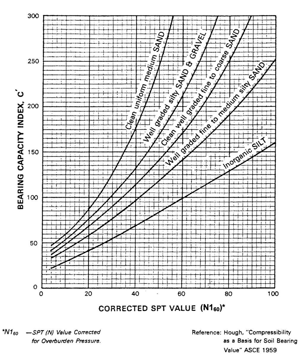
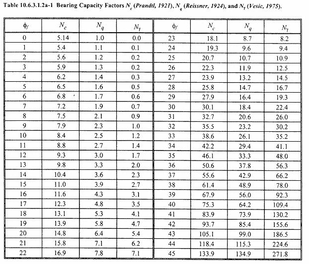
3 Student In-Class Exercise Shallow Foundation The soil profile, with SPT N-value and N1 60, is provided in the schematic diagram below: a) Compute the settlement of a strip footing under the vertical load of 10 k/ft using the Hough chart of bearing capacity Index c. Use 2:1 distribution of stress method to calculate change in vertical stress, σ z. b) Use f f =30 and γ total =120 psf for the silty sand gravel. Assuming the depth of embedment D f = 5 ft, compute the nominal bearing capacity. Note: Bearing capacity factors N c, N q, and N γ, for f f =30, are 30.1, 18.4 and 22.4, respectively. (AASHTO Table a-1) 1
4 2
5 b) The nominal bearing capacity equation is: q n = cn c + γd f N q C wq + 0.5γB f N γ C wγ For the given information, variables for this equation are defined as follows: c = 0 psf Cohesion intercept D f =5 ft Depth of embedment of the footing γ=120 pcf Density of the soil above the groundwater table B f =5 ft Width of the footing Cw γ = 1.0 Groundwater table is greater than 1.5 times footing width below bearing level, therefore correction factor is 1.0. If groundwater table is less than 1.5 times footing width below bearing level, correction factor = 0.5 Solving the nominal bearing capacity equation for this footing gives a bearing capacity of: q n = 0 + (120 pcf)(5 ft)(18.4)(1) + 0.5( l20 pcf)(5 ft)(22.4)(1.0) = psf a) Settlement of strip footing and effective stress diagram, 3
6 10 q = ksf 5 q = 2000 psf 2 layer 5 ft σ' vo =600 psf B 5 σ v = q, σ v = 2000 = 1000 psf B + Z (5 + 5) 1 σ o + σ v H = H log c C σ o H = 10 log = ft ft σ' o =1488 psf 4
7 5 σ v = 2000 = 500 psf (5 + 15) H = 10 log = ft The total settlement = ft ft = ft = 1.2 in 5
8 In- Class Exercise Given: Total factored load Q = 160 kips/pile The soil profile with pertinent soil properties are shown in Fig. (1) Required : a) Based on ODOT BDM Article , select a suitable pile size (diameter) for friction pile b) Determine the estimated length for the selected friction pile size using R ndr =R s +R P Where: R s : Unfactored Resistance provided along the side of pile, LRFD R P : Unfactored Resistance provided at the pile tip, LRFD The DRIVEN program is used to generate the skin friction and end bearing values for 12 inch and 16 inch pipe pile in the given soil profile. The DRIVEN analysis results are given in Tables (1 & 2) and plotted in Figures (2 & 3). c) Assume downdrag force in the clay layer is fully developed, (i.e., DD = S dd = 31 kips for 12 inch pipe pile), estimate pile length to account for downdrag force. d) Check the adequacy of 12 inch pipe pile regarding the downdrag force. If it is not adequate, check the adequacy of using 16 inch pie pile and estimate the required pile length. Assume the downdrag force (DD) = 41 kips. 1
9 Q 20 Clay S u = 500 psf γ = 120 lb/ft 3 Sand f= 35 o γ = 125 lb/ft 3 Pipe Pile Figure (1) 2
10 Table 1: Driving Summary of Capacity for 12 inch Pipe pile Table 2: Driving Summary of Capacity for 16 inch Pipe pile 3
11 Figure 2: Bearing Capacity Graph, 12 inch Pipe Pile Figure 3: Bearing Capacity Graph, 16 inch Pipe Pile 4
12 Solution: (a) The nominal driving resistance required to support the total factored load (Q) is Rndr = Q φ DYN Where R ndr = Ultimate Bearing Value (Kips) Q = Total factored load for the highest loaded pile at each substructure unit (Kips) φ = Resistance factor for driven piles DYN Q R = 16 0 φ = 230 Kips ndr = DYN 0.7 Referring to ODOT BDM Article b Pipe Pile Diameter Maximum R ndr 12 inch 250 kips 14 inch 300 kips 16 inch 390 kips Use 12 inch pipe pile Max. R ndr =250 Kips >230 Kips OK. 5
13 (b) The estimated length for the friction pile using Tale (1) and Fig. (2) is L= 42 feet (c) The total nominal driving resistance, R ndr, for 12 inch pile required is R = R + ndr Sdd R n Where R Sdd = skin friction which must be overcome during driving through downdrag zone (kips) R n γ iqi = ( ) φ dyn + γ DD p φ dyn From Table (1) and Fig. (2), R Sdd = 31 kips [ ] (31) = 322 R = kips > 250 kips.n.g. ndr
14 (d) Use 16 inch pipe pile Max R ndr = 390 kips The total nominal driving resistance, R ndr, required is R = R + ndr Sdd R n Where R Sdd = skin friction which must be overcome during driving through downdrag zone (kips) R n γ iqi = ( ) φ dyn + γ DD p φ dyn From Table (2) and Fig. (3), R Sdd = 41 kips [ ] (41) = 352 R = kips < 390 kips OK. ndr The estimated length for the friction pile using Tale (2) and Fig. (3) is L = 37 feet 7
SHEET PILE WALLS. Mehdi Mokhberi Islamic Azad University
 SHEET PILE WALLS Mehdi Mokhberi Islamic Azad University Lateral Support In geotechnical engineering, it is often necessary to prevent lateral soil movements. Tie rod Anchor Sheet pile Cantilever retaining
INTI COLLEGE MALAYSIA
 EGC373 (F) / Page 1 of 5 INTI COLLEGE MALAYSIA UK DEGREE TRANSFER PROGRAMME INTI ADELAIDE TRANSFER PROGRAMME EGC 373: FOUNDATION ENGINEERING FINAL EXAMINATION : AUGUST 00 SESSION This paper consists of
This document downloaded from vulcanhammer.net vulcanhammer.info Chet Aero Marine
 This document downloaded from vulcanhammer.net vulcanhammer.info Chet Aero Marine Don t forget to visit our companion site http://www.vulcanhammer.org Use subject to the terms and conditions of the respective
Design of a Balanced-Cantilever Bridge
 Design of a Balanced-Cantilever Bridge CL (Bridge is symmetric about CL) 0.8 L 0.2 L 0.6 L 0.2 L 0.8 L L = 80 ft Bridge Span = 2.6 L = 2.6 80 = 208 Bridge Width = 30 No. of girders = 6, Width of each girder
Design of RC Retaining Walls
 Lecture - 09 Design of RC Retaining Walls By: Prof Dr. Qaisar Ali Civil Engineering Department UET Peshawar www.drqaisarali.com 1 Topics Retaining Walls Terms Related to Retaining Walls Types of Retaining
PECivilExam.com. Copyright 2015 Pecivilexam.com all rights reserved- E-Book Geotechnical Depth Exam: 80 problems
 PECivilExam.com PE Civil Exam 80- Geotechnical Questions & Answers (pdf Format) For Depth Exam (Evening Session) PE Civil Depth Exam (Evening Session): This practice exam contains 80- Geotechnical questions,
ADVANCED SOIL MECHANICS FINAL EXAM (TAKE HOME):DUE THURSDAY, DECEMBER 19, 6PM.
:DUE THURSDAY, DECEMBER 19, 6PM.") 14.531 ADVANCED SOIL MECHANICS FINAL EXAM (TAKE HOME):DUE THURSDAY, DECEMBER 19, 2013 @ 6PM. Problem #1. Field load tests on strip footings yielded the test data provided below in Figure 1 and Table 1
14.531 ADVANCED SOIL MECHANICS FINAL EXAM (TAKE HOME):DUE THURSDAY, DECEMBER 19, 2013 @ 6PM. Problem #1. Field load tests on strip footings yielded the test data provided below in Figure 1 and Table 1
Civil Engineering, Surveying and Environmental Consulting WASP0059.ltr.JLS.Mich Ave Bridge Geotech.docx
 2365 Haggerty Road South * Canton, Michigan 48188 P: 734-397-3100 * F: 734-397-3131 * www.manniksmithgroup.com August 29, 2012 Mr. Richard Kent Washtenaw County Parks and Recreation Commission 2330 Platt
CHAPTER 8 CALCULATION THEORY
 CHAPTER 8 CALCULATION THEORY. Volume 2 CHAPTER 8 CALCULATION THEORY Detailed in this chapter: the theories behind the program the equations and methods that are use to perform the analyses. CONTENTS CHAPTER
NCHRP LRFD Design Specifications for Shallow Foundations TRB AFS30 Committee Meeting January 26, 2011
 Geotechnical Engineering Research Laboratory Dept. of Civil and Environmental Engineering University of Massachusetts Lowell. NCHRP 24-31 LRFD Design Specifications for Shallow Foundations TRB AFS3 Committee
PILE SETUP LA-1 EXPERIENCE. Ching-Nien Tsai, P.E.
 PILE SETUP LA-1 EXPERIENCE Ching-Nien Tsai, P.E. Bayou Lafourche Mississippi River GEOTECHNICAL INVESTIGATION PROGRAM 102 CPT soundings Depths from 100 feet to 200 feet 118 borings Depths from
OVERVIEW REVIEW OF FOUNDATIONS & SOILS ENG.
 Soil Borings. 14.485 CAPSTONE DESIGN OVERVIEW REVIEW OF 14.431 FOUNDATIONS & SOILS ENG. Geotechnical Report (not covered). Bearing Pressure Calculations. Settlement Calculations. Lateral Earth Pressure
Lesson 25. Static Pile Load Testing, O-cell, and Statnamic. Reference Manual Chapter 18
 Lesson 25 Static Pile Load Testing, O-cell, and Statnamic Reference Manual Chapter 18 STATIC LOAD TESTING Most accurate method to determine static pile capacity Perform at design or construction stage
INTRODUCTION TO STATIC ANALYSIS PDPI 2013
 INTRODUCTION TO STATIC ANALYSIS PDPI 2013 What is Pile Capacity? When we load a pile until IT Fails what is IT Strength Considerations Two Failure Modes 1. Pile structural failure controlled by allowable
Chapter (3) Ultimate Bearing Capacity of Shallow Foundations
 Ultimate Bearing Capacity of Shallow Foundations") Chapter (3) Ultimate Bearing Capacity of Shallow Foundations Introduction To perform satisfactorily, shallow foundations must have two main characteristics: 1. They have to be safe against overall shear
Chapter (3) Ultimate Bearing Capacity of Shallow Foundations Introduction To perform satisfactorily, shallow foundations must have two main characteristics: 1. They have to be safe against overall shear
LRFD GEOTECHNICAL IMPLEMENTATION
 LRFD GEOTECHNICAL IMPLEMENTATION Ching-Nien Tsai, P.E. LADOTD Pavement and Geotechnical Services In Conjunction with LTRC WHY LRFD FHWA deadline - October 2007 LRFD is a better method Risk is quantified
Chapter (11) Pile Foundations
 Pile Foundations") Chapter (11) Introduction Piles are structural members that are made of steel, concrete, or timber. They are used to build pile foundations (classified as deep foundations) which cost more than shallow
Chapter (11) Introduction Piles are structural members that are made of steel, concrete, or timber. They are used to build pile foundations (classified as deep foundations) which cost more than shallow
LRFD Application in Driven Piles (Recent Development in Pavement & Geotech at LTRC)
") LRFD Application in Driven Piles (Recent Development in Pavement & Geotech at LTRC) 2007 Louisiana Transportation Engineering Conference February 12, 2007 Sungmin Sean Yoon, Ph. D., P.E. and Murad Abu-Farsakh,
LRFD Application in Driven Piles (Recent Development in Pavement & Geotech at LTRC) 2007 Louisiana Transportation Engineering Conference February 12, 2007 Sungmin Sean Yoon, Ph. D., P.E. and Murad Abu-Farsakh,
Reinforced Soil Structures Reinforced Soil Walls. Prof K. Rajagopal Department of Civil Engineering IIT Madras, Chennai
 Geosynthetics and Reinforced Soil Structures Reinforced Soil Walls continued Prof K. Rajagopal Department of Civil Engineering IIT Madras, Chennai e-mail: gopalkr@iitm.ac.inac in Outline of the Lecture
CIVE.4850 CAPSTONE DESIGN Module 3 Geotechnical Engineering 2016 F.E. EXAM. Slide 1 of 59. Revised 02/2016
 2016 F.E. EXAM Slide 1 of 59 2016 F.E. EXAM 8-13% GEOL.3250 (optional) CIVE.3300 & CIVE.3330 CIVE.4310 Slide 2 of 59 CIVE.4850 CAPSTONE DESIGN 2016 FUNDAMENTALS OF ENGINEERING (FE) EXAM CALCULATOR POLICY
TRANSPORTATION RESEARCH BOARD. Static and Seismic Design of Piles for Downdrag. Thursday, October 4, :00-3:30 PM ET
 TRANSPORTATION RESEARCH BOARD Static and Seismic Design of Piles for Downdrag Thursday, October 4, 2018 2:00-3:30 PM ET The Transportation Research Board has met the standards and requirements of the Registered
RETAINING WALL LOADS: Horizontal Equivalent Fluid Pressure = pcf. (Load Case = Soil)
") QuickWall 8.0 - RETAINING WALL ANALYSIS AND DESIGN ================================================================================ Job ID : Job Description : Designed By : ================================================================================
QuickWall 8.0 - RETAINING WALL ANALYSIS AND DESIGN ================================================================================ Job ID : Job Description : Designed By : ================================================================================
WIND TUNNEL TESTING GEOTECHNICAL STUDY
 WIND TUNNEL TESTING Wind tunnel testing was conducted by the Boundary Layer Wind Tunnel Laboratory (BLWTL) at the University of Western Ontario (UWO) to develop wind load time histories for the chimney.
Transmission Line Design Structures & Foundations TADP 549
 Transmission Line Design Structures & Foundations TADP 549 Steel Poles - Direct Embedment Foundations - Point of Fixity Presentation 6.3 Dr. Prasad Yenumula Transmission & Distribution Program Reference
Dr. Mohammed E. Haque, P.E. Lecture Notes
 nalysis of Selected Determinate Structural Systems Planar Trusses Method of Joints Planar Trusses Method of Sections Pinned Frames with Multi-force Members Retaining Walls OS321Haque 1 Planar Trusses Method
NCHRP LRFD DESIGN SPECIFICATIONS FOR SHALLOW FOUNDATIONS. Final Report September 2009 APPENDIX G BIAS CALCULATION EXAMPLES
 NCHRP 4-3 LRFD DESIGN SPECIFICATIONS FOR SHALLOW FOUNDATIONS Final Report September 009 APPENDIX G BIAS CALCULATION EXAMPLES Prepared for National Cooperative Highway Research Program Transportation Research
Chapter (6) Geometric Design of Shallow Foundations
 Geometric Design of Shallow Foundations") Chapter (6) Geometric Design of Shallow Foundations Introduction As we stated in Chapter 3, foundations are considered to be shallow if if [D (3 4)B]. Shallow foundations have several advantages: minimum
Chapter (6) Geometric Design of Shallow Foundations Introduction As we stated in Chapter 3, foundations are considered to be shallow if if [D (3 4)B]. Shallow foundations have several advantages: minimum
Chapter 6 Bearing Capacity
 Chapter 6 Bearing Capacity 6-1. Scope This chapter provides guidance for the determination of the ultimate and allowable bearing stress values for foundations on rock. The chapter is subdivided into four
REQUIRED: Calculate the total consolidation settlement in the CL layers due to the addition of the 5 ft of fill.
 Geotechnical Engineering Research Laboratory One University Avenue Edward L. Hajduk, D.Eng, PE Lecturer Lowell, Massachusetts 01854 Tel: (978) 934-2621 Fax: (978) 934-3052 e-mail: Edward_Hajduk@uml.edu
(THIS IS ONLY A SAMPLE REPORT OR APPENDIX OFFERED TO THE USERS OF THE COMPUTER PROGRAM
 C A U T I O N!! (THIS IS ONLY A SAMPLE REPORT OR APPENDIX OFFERED TO THE USERS OF THE COMPUTER PROGRAM EQLique&Settle2. THE AUTHOR IS HEREBY RELEASED OF ANY LIABILITY FOR ANY INCORRECT USE OF THIS SAMPLE
Deep Foundations 2. Load Capacity of a Single Pile
 Deep Foundations 2 Load Capacity of a Single Pile All calculations of pile capacity are approximate because it is almost impossible to account for the variability of soil types and the differences in the
Compute the lateral force per linear foot with sloping backfill and inclined wall. Use Equation No. 51, page 93. Press ENTER.
 Sample Problems Problem 5.1 A gravity retaining wall is supporting a cohesionless soil. The active lateral force per linear foot of the retaining wall is most nearly (A) 5,000 lb/ft (B) 6,000 lb/ft (C)
ALUMINUM STRUCTURAL PLATE HEADWALLS AASHTO LRFD BASIS OF DESIGN
 ALUMINUM STRUCTURAL PLATE EADWALLS AASTO LRFD BASIS OF DESIGN LANE ENTERPRISES, INC. www.lane-enterprises.com Required Backfill and Load Cases: ALUMINUM STRUCTURAL PLATE EADWALLS BASIS OF DESIGN Backfill
Chapter (4) Ultimate Bearing Capacity of Shallow Foundations (Special Cases)
 Ultimate Bearing Capacity of Shallow Foundations (Special Cases)") Chapter (4) Ultimate earing Capacity of Shallow Foundations (Special Cases) Ultimate.C. of Shallow Foundations (Special Cases) Introduction The ultimate bearing capacity theories discussed in Chapter 3
Chapter (4) Ultimate earing Capacity of Shallow Foundations (Special Cases) Ultimate.C. of Shallow Foundations (Special Cases) Introduction The ultimate bearing capacity theories discussed in Chapter 3
Appendix K Design Examples
 Appendix K Design Examples Example 1 * Two-Span I-Girder Bridge Continuous for Live Loads AASHTO Type IV I girder Zero Skew (a) Bridge Deck The bridge deck reinforcement using A615 rebars is shown below.
Use of RMR to Improve Determination of the Bearing Resistance of Rock
 Creating Value Delivering Solutions Use of RMR to Improve Determination of the Bearing Resistance of Rock Scott Zang, P.E. Michael Baker Jr., Inc. ASD Design Q v allowable is a presumptive allowable bearing
Technical Supplement 14Q. Abutment Design for Small Bridges. (210 VI NEH, August 2007)
") Technical Supplement 14Q (10 VI NEH, August 007) Issued August 007 Cover photo: Design of abutments for small bridges reuires geotechnical analysis. Advisory Note Techniues and approaches contained in
Technical Supplement 14Q (10 VI NEH, August 007) Issued August 007 Cover photo: Design of abutments for small bridges reuires geotechnical analysis. Advisory Note Techniues and approaches contained in
ERRATA for PE Civil Structural Practice Exam ISBN Copyright 2014 (July 2016 Second Printing) Errata posted
 Errata posted") Errata posted 8-16-2017 Revisions are shown in red. Question 521, p. 47: Question 521 should read as follows: 521. The W10 22 steel eam (Fy = 50 ksi) shown in the figure is only raced at the center of
Errata posted 8-16-2017 Revisions are shown in red. Question 521, p. 47: Question 521 should read as follows: 521. The W10 22 steel eam (Fy = 50 ksi) shown in the figure is only raced at the center of
DEPARTMENT OF TRANSPORTATION DIVISION: MATERIALS REPORT COVER SHEET
 LD-450 7/01/09 DEPARTMENT OF TRANSPORTATION DIVISION: MATERIALS REPORT COVER SHEET Geotechnical Engineering Report Culverts March 3, 2017 AECOM Technical Services, Inc. Germantown, Maryland AECOM Germantown,
Full-Scale Testing of Blast-Induced Liquefaction Downdrag on Driven Piles in Sand
 Brigham Young University BYU ScholarsArchive All Theses and Dissertations 2017-07-01 Full-Scale Testing of Blast-Induced Liquefaction Downdrag on Driven Piles in Sand Luke Ian Kevan Brigham Young University
Neutral Plane Method for Drag Force of Deep Foundations and the AASHTO LRFD Bridge Design Specifications
 Neutral Plane Method for Drag Force of Deep Foundations and the AASHTO LRFD Bridge Design Specifications Timothy C. Siegel, P.E., G.E., D.GE Dan Brown and Associates, PC, Knoxville, Tennessee USA Rich
Objectives. In this section you will learn the following. Development of Bearing Capacity Theory. Terzaghi's Bearing Capacity Theory
 Objectives In this section you will learn the following Development of Bearing Capacity Theory Terzaghi's Bearing Capacity Theory Assumptions in Terzaghi s Bearing Capacity Theory. Meyerhof's Bearing Capacity
INDOT/Purdue Pile Driving Method for Estimation of Axial Capacity
 1 2015 Purdue Road School Transportation and Conference and Expo INDOT/Purdue Pile Driving Method for Estimation of Axial Capacity Zaheer, Mir, INDOT Salgado, Rodrigo, Purdue University Prezzi, Monica,
AB Engineering Manual
 AB Engineering Manual Allan Block Retaining Walls FOREWORD This manual presents the techniques used by Allan Block in our engineering practice to design retaining walls. It is not intended as a textbook
LRFD Calibration of Axially-Loaded Concrete Piles Driven into Louisiana Soils
 LRFD Calibration of Axially-Loaded Concrete Piles Driven into Louisiana Soils Louisiana Transportation Conference February 10, 2009 Sungmin Sean Yoon, Ph. D., P.E. (Presenter) Murad Abu-Farsakh, Ph. D.,
BEARING CAPACITY SHALLOW AND DEEP FOUNDATIONS
 BEARING CAPACITY SHALLOW AND DEEP FOUNDATIONS CONTENTS: 1.0 INTRODUCTION 2.0 SHALLOW FOUNDATIONS 2.1 Design criteria 2.2 Spreading load 2.3 Types of foundations 2.4 Ground failure modes 2.5 Definitions
Additional Pile Design Considerations
 Additional Pile Design Considerations PDCA 2015 Professor Driven Pile Institute Patrick Hannigan GRL Engineers, Inc. What Are Additional Pile Design Considerations? Time Dependent Soil Strength Changes
Chapter (5) Allowable Bearing Capacity and Settlement
 Allowable Bearing Capacity and Settlement") Chapter (5) Allowable Bearing Capacity and Settlement Introduction As we discussed previously in Chapter 3, foundations should be designed for both shear failure and allowable settlement. So the allowable
Chapter (5) Allowable Bearing Capacity and Settlement Introduction As we discussed previously in Chapter 3, foundations should be designed for both shear failure and allowable settlement. So the allowable
Calibration of Resistance Factors for Drilled Shafts for the 2010 FHWA Design Method
 Calibration of Resistance Factors for Drilled Shafts for the 21 FHWA Design Method Murad Y. Abu-Farsakh, Ph.D., P.E. Qiming Chen, Ph.D., P.E. Md Nafiul Haque, MS Feb 2, 213 213 Louisiana Transportation
Axially Loaded Piles
 Axially Loaded Piles 1 t- Curve Method using Finite Element Analysis The stress-strain relationship for an axially loaded pile can be described through three loading mechanisms: axial deformation in the
Hyperbolic Soil Bearing Capacity
 1 Introduction Hyperbolic Soil Bearing Capacity This example involves analyzing the bearing capacity of a round footing. The example is useful for illustrating several SIGMA/W features and procedures,
AB Engineering Manual
 AB Engineering Manual Allan Block Retaining Walls This manual presents the techniques used by Allan Block in our engineering practice to design retaining walls. It is not intended as a textbook of soil
EN Eurocode 7. Section 3 Geotechnical Data Section 6 Spread Foundations. Trevor L.L. Orr Trinity College Dublin Ireland.
 EN 1997 1: Sections 3 and 6 Your logo Brussels, 18-20 February 2008 Dissemination of information workshop 1 EN 1997-1 Eurocode 7 Section 3 Geotechnical Data Section 6 Spread Foundations Trevor L.L. Orr
SOIL MECHANICS Assignment #5: Stresses in a Soil Mass.
 Geotechnical Engineering Research Laboratory One University Avenue Lowell, Massachusetts 01854 Edward L. Hajduk, D.Eng, PE Lecturer PA105D Tel: (978) 934 2621 Fax: (978) 934 3052 e mail: Edward_Hajduk@uml.edu
Module 7 (Lecture 25) RETAINING WALLS
 RETAINING WALLS") Module 7 (Lecture 25) RETAINING WALLS Topics Check for Bearing Capacity Failure Example Factor of Safety Against Overturning Factor of Safety Against Sliding Factor of Safety Against Bearing Capacity Failure
Module 7 (Lecture 25) RETAINING WALLS Topics Check for Bearing Capacity Failure Example Factor of Safety Against Overturning Factor of Safety Against Sliding Factor of Safety Against Bearing Capacity Failure
(Lecture 18) MAT FOUNDATIONS
 MAT FOUNDATIONS") Module 5 (Lecture 18) MAT FOUNDATIONS Topics 1.1 FIELD SETTLEMENT OBSERVATIONS FOR MAT FOUNDATIONS 1.2 COMPENSATED FOUNDATIONS 1.3 Example FIELD SETTLEMENT OBSERVATIONS FOR MAT FOUNDATIONS Several field
Module 5 (Lecture 18) MAT FOUNDATIONS Topics 1.1 FIELD SETTLEMENT OBSERVATIONS FOR MAT FOUNDATIONS 1.2 COMPENSATED FOUNDATIONS 1.3 Example FIELD SETTLEMENT OBSERVATIONS FOR MAT FOUNDATIONS Several field
A presentation of UniPile software for calculation of Capacity, Drag Force, Downdrag, and Settlement for Piles and Piled Foundations
 528 River Road, Ottawa, Ontario, Canada, K1V 1E9 E: info@unisoftgs.com A presentation of UniPile software for calculation of Capacity, Drag Force, Downdrag, and Settlement for Piles and Piled Foundations
Introduction to Soil Mechanics
 Introduction to Soil Mechanics Sela Sode and Colin Jones WILEY Blackwell Contents Preface Dedication and Acknowledgments List of Symbols Soil Structure 1.1 Volume relationships 1.1.1 Voids ratio (e) 1.1.2
CE 442 GEOTECHNICAL ENGINEERING SESSIONAL II
 CE 442 GEOTECHNICAL ENGINEERING SESSIONAL II Department of Civil Engineering Ahsanullah University of Science and Technology December, 2017 Preface The substructure or foundation is the part of a structure
TABLE OF CONTENTS APPENDICES
 TABLE OF CONTENTS Introduction... 1 Proposed Construction... 2 Site Conditions... 3 Site Geology... 4 Subsurface Exploration... 5 SPT Borings... 5 CPT Probes... 6 Laboratory Testing... 6 Subsurface Conditions...
TABLE OF CONTENTS CHAPTER TITLE PAGE TITLE PAGE DECLARATION DEDIDATION ACKNOWLEDGEMENTS ABSTRACT ABSTRAK
 TABLE OF CONTENTS CHAPTER TITLE PAGE TITLE PAGE DECLARATION DEDIDATION ACKNOWLEDGEMENTS ABSTRACT ABSTRAK TABLE OF CONTENTS LIST OF TABLE LIST OF FIGURES LIST OF SYMBOLS LIST OF APENDICES i ii iii iv v
Theory of Shear Strength
 SKAA 1713 SOIL MECHANICS Theory of Shear Strength Prepared by, Dr. Hetty 1 SOIL STRENGTH DEFINITION Shear strength of a soil is the maximum internal resistance to applied shearing forces The maximum or
Theory of Shear Strength
 MAJ 1013 ADVANCED SOIL MECHANICS Theory of Shear Strength Prepared by, Dr. Hetty 1 Strength of different materials Steel Concrete Soil Tensile strength Compressive strength Shear strength Complex behavior
Analysis of a single pile settlement
 Engineering manual No. 14 Updated: 06/2018 Analysis of a single pile settlement Program: Pile File: Demo_manual_14.gpi The objective of this engineering manual is to explain the application of the GEO
AN EMPLOYEE OWNED COMPANY
 CTL Engineering, Inc. 2860 Fisher Road, P.O. Box 4448, Columbus, Ohio 43204338 Phone: 614/2768123 Fax: 614/2766377 Email: ctl@ctleng.com AN EMPLOYEE OWNED COMPANY Consulting Engineers Testing Inspection
vulcanhammer.net This document downloaded from
 This document downloaded from vulcanhammer.net since 1997, your source for engineering information for the deep foundation and marine construction industries, and the historical site for Vulcan Iron Works
8/11/14. Sheet 1. Colonial Flag 9390 So 300 West Sandy, UT
 8/11/14 Sheet 1 990 So 00 West Sandy, UT 84070 800 78-0500 Street Banner Sign Cloth Tension Calculations for Simple Span with Uniform Loads. Sign Cloth Span Sign Cloth Length Stretched Sign Cloth Sag Sign
A Comparative Study on Bearing Capacity of Shallow Foundations in Sand from N and /
 DOI 10.1007/s40030-017-0246-7 ORIGINAL CONTRIBUTION A Comparative Study on Bearing Capacity of Shallow Foundations in Sand from N and / V. A. Sakleshpur 1 C. N. V. Satyanarayana Reddy 1 Received: 9 January
Reliability of Settlement Analysis for Shallow Foundations
 Geotechnical Engineering Research Laboratory University of Massachusetts Lowell, MA USA Reliability of Settlement Analysis for Shallow Foundations 14.533 ADVANCED FOUNDATION ENGINEERING Fall 2013 Samuel
GEOTECHNICAL ENGINEERING ECG 503 LECTURE NOTE ANALYSIS AND DESIGN OF RETAINING STRUCTURES
 GEOTECHNICAL ENGINEERING ECG 503 LECTURE NOTE 07 3.0 ANALYSIS AND DESIGN OF RETAINING STRUCTURES LEARNING OUTCOMES Learning outcomes: At the end of this lecture/week the students would be able to: Understand
Drilled Shaft Foundations in Limestone. Dan Brown, P.E., Ph.D. Dan Brown and Associates
 Drilled Shaft Foundations in Limestone Dan Brown, P.E., Ph.D. Dan Brown and Associates Foundation Engineering How we teach our students Fundamental understanding of soil and rock behavior (good!) Focus
ASD and LRFD Methods Codes and Economics of Dynamic Testing ASTM D4945
 ASD and LRFD Methods Codes and Economics of Dynamic Testing ASTM D4945 Load Testing. Static Load Testing ASTM D1143 Deadload Testing React. Piles/Anchors Static Load Tests are the standard Costly: Need
LOAD RESISTANCE FACTOR DESIGN (LRFD) FOR DRIVEN PILES BASED ON DYNAMIC METHODS WITH ASSESSMENT OF SKIN AND TIP RESISTANCE FROM PDA SIGNALS
 FOR DRIVEN PILES BASED ON DYNAMIC METHODS WITH ASSESSMENT OF SKIN AND TIP RESISTANCE FROM PDA SIGNALS") LOAD RESISTANCE FACTOR DESIGN (LRFD) FOR DRIVEN PILES BASED ON DYNAMIC METHODS WITH ASSESSMENT OF SKIN AND TIP RESISTANCE FROM PDA SIGNALS By ARIEL PEREZ PEREZ A THESIS PRESENTED TO THE GRADUATE SCHOOL
LOAD RESISTANCE FACTOR DESIGN (LRFD) FOR DRIVEN PILES BASED ON DYNAMIC METHODS WITH ASSESSMENT OF SKIN AND TIP RESISTANCE FROM PDA SIGNALS By ARIEL PEREZ PEREZ A THESIS PRESENTED TO THE GRADUATE SCHOOL
Bearing Capacity of Soils in Deep Foundations Course No. CE0148 PDH: 5
 Bearing Capacity of Soils in Deep Foundations Course No. CE0148 PDH: 5 ** PLEASE NOTE: THIS COURSE IS A SUBSECTION OF COURSE # CE0009 ** In order to obtain credit for this course, the following steps listed
Module 7 (Lecture 27) RETAINING WALLS
 RETAINING WALLS") Module 7 (Lecture 27) RETAINING WALLS Topics 1.1 RETAINING WALLS WITH METALLIC STRIP REINFORCEMENT Calculation of Active Horizontal and vertical Pressure Tie Force Factor of Safety Against Tie Failure
Module 7 (Lecture 27) RETAINING WALLS Topics 1.1 RETAINING WALLS WITH METALLIC STRIP REINFORCEMENT Calculation of Active Horizontal and vertical Pressure Tie Force Factor of Safety Against Tie Failure
THE STRUCTURAL DESIGN OF PILE FOUNDATIONS BASED ON LRFD FOR JAPANESE HIGHWAYS
 THE STRUCTURAL DESIGN OF PILE FOUNDATIONS BASED ON LRFD FOR JAPANESE HIGHWAYS Hideaki Nishida 1,Toshiaki Nanazawa 2, Masahiro Shirato 3, Tetsuya Kohno 4, and Mitsuaki Kitaura 5 Abstract One of the motivations
water proofing will relatively long time fully completed) be provided 10 storey building (15x25m) original GWT position 1 sat = 20 kn/m 3
 be provided 10 storey building (15x25m) original GWT position 1 sat = 20 kn/m 3") P1 Question: An excavation will be made for a ten storey 15x25 m building. Temporary support of earth pressure and water pressure will be made by deep secant cantilever pile wall. The gross pressure due
P1 Question: An excavation will be made for a ten storey 15x25 m building. Temporary support of earth pressure and water pressure will be made by deep secant cantilever pile wall. The gross pressure due
S E C T I O N 1 2 P R O D U C T S E L E C T I O N G U I D E - H E L I C A L S C R E W P I L E F O U N D A T I O N S
 1. P R O D U C T S E L E C T I O N G U I D E - H E L I C A L S C R E W P I L E F O U N D A T I O N S Helical foundation pile includes a lead and extension(s). The lead section is made of a central steel
Tower Cranes & Foundations The Interface & CIRIA C654 Stuart Marchand C.Eng. FICE FIStructE Director Wentworth House Partnership
 Tower Cranes & Foundations The Interface & CIRIA C654 Stuart Marchand C.Eng. FICE FIStructE Director Wentworth House Partnership EXAMPLES OF TOWER CRANE FOUNDATION TYPES Rail mounted Pad Base Piled Base
Piles and Pile Foundations
 Piles and Pile Foundations Carlo Viggiani, Alessandro Mandolini and Gianpiero Russo * j \ Spon Press an imprint of Taylor & Francis LONDON AND NEWYORK Contents List of illustrations Introduction PART I
Reliability Analysis of Anchored and Cantilevered Flexible Retaining Structures
 LSD2003: International Workshop on Limit State Design in Geotechnical Engineering Practice Phoon, Honjo & Gilbert (eds) 2003 World Scientific Publishing Company Reliability Analysis of Anchored and Cantilevered
Supplementary Problems for Chapter 7
 Supplementary Problems for Chapter 7 Problem 7.1 consolidation test has been carried out on a standard 19 mm thick clay sample. The oedometer s deflection gauge indicated 1.66 mm, just before the removal
Chapter (7) Lateral Earth Pressure
 Lateral Earth Pressure") Chapter (7) Lateral Earth Pressure Introduction Vertical or near vertical slopes of soil are supported by retaining walls, cantilever sheet-pile walls, sheet-pile bulkheads, braced cuts, and other similar
Chapter (7) Lateral Earth Pressure Introduction Vertical or near vertical slopes of soil are supported by retaining walls, cantilever sheet-pile walls, sheet-pile bulkheads, braced cuts, and other similar
Liquefaction and Foundations
 Liquefaction and Foundations Amit Prashant Indian Institute of Technology Gandhinagar Short Course on Seismic Design of Reinforced Concrete Buildings 26 30 November, 2012 What is Liquefaction? Liquefaction
Lecture 7 Two-Way Slabs
 Lecture 7 Two-Way Slabs Two-way slabs have tension reinforcing spanning in BOTH directions, and may take the general form of one of the following: Types of Two-Way Slab Systems Lecture 7 Page 1 of 13 The
UNIT II SHALLOW FOUNDATION
 Introduction UNIT II SHALLOW FOUNDATION A foundation is a integral part of the structure which transfer the load of the superstructure to the soil. A foundation is that member which provides support for
Implementation of Pile Setup in the LRFD Design of Driven Piles in Louisiana
 Implementation of Pile Setup in the LRFD Design of Driven Piles in Louisiana Md. Nafiul Haque (Ph.D. Candidate) Murad Y. Abu-Farsakh, Ph.D., P.E. March 1, 2016 Louisiana Transportation Conference OUTLINE
SOIL MECHANICS: palgrave. Principles and Practice. Graham Barnes. macmiiian THIRD EDITION
 SOIL MECHANICS: Principles and Practice THIRD EDITION Graham Barnes palgrave macmiiian 'running Contents Preface xii Fine soil 19 List of symbols xiv Mass structure 21 Note on units xix Degree of weathering
TABLE OF CONTENTS SECTION TITLE PAGE 2 PRINCIPLES OF SEISMIC ISOLATION OF BRIDGES 3
 TABLE OF CONTENTS SECTION TITLE PAGE 1 INTRODUCTION 1 2 PRINCIPLES OF SEISMIC ISOLATION OF BRIDGES 3 3 ANALYSIS METHODS OF SEISMICALLY ISOLATED BRIDGES 5 3.1 Introduction 5 3.2 Loadings for the Analysis
DESIGNING FOR DOWNDRAG ON UNCOATED AND BITUMEN COATED PILES
 DESIGNING FOR DOWNDRAG ON UNCOATED AND BITUMEN COATED PILES Jean-Louis BRIAUD, PhD, PE President of ISSMGE Professor and Holder of the Buchanan Chair Texas A&M University Piling and Deep Foundations Middle
GEOTECHNICAL REPORT Loup Loup Bridge Replacement Okanogan County, Washington
 GEOTECHNICAL REPORT Loup Loup Bridge Replacement Okanogan County, Washington Prepared for: Nicholls Engineering Project No. 130182 May 15, 2014 ASPECT CONSULTING Contents 1 Introduction... 1 2 Scope of
Use of Ultra-High Performance Concrete in Geotechnical and Substructure Applications
 Use of Ultra-High Performance Concrete in Geotechnical and Substructure Applications i PI: Muhannad Suleiman Co-PI: Sri Sritharan Graduate Research Assistant: Thomas L. Vande Voort January 13, 29 IOWA
A Thesis presented to the Faculty of the Graduate School at the University of Missouri-Columbia
 LRFD for Settlement Analyses of Shallow Foundations and Embankments ------ Developed Resistance Factors for Consolidation Settlement Analyses A Thesis presented to the Faculty of the Graduate School at
R.M.HARW & ASSOCIATES LTD. GEOTECHNICAL INVESTIGATION PROPOSED BRIDGE SITE. HELAVA CREEKl MILE MACKENZIE HIGHWAY E-2510 OCTOBER 16, 1973
 El R.M.HARW & ASSOCIATES LTD. GEOTECHNICAL INVESTIGATION PROPOSED BRIDGE SITE HELAVA CREEKl MILE 616.4 MACKENZIE HIGHWAY E-2510 OCTOBER 16, 1973 R,M,HARDV & ASSOCIATES LTD. CONSULTING ENGINEERING & TESTING
Chapter 7: Settlement of Shallow Foundations
 Chapter 7: Settlement of Shallow Foundations Introduction The settlement of a shallow foundation can be divided into two major categories: (a) elastic, or immediate settlement and (b) consolidation settlement.
 R-1 Conveyor Relocation Project Legend 0 500 1000 1500 ft. This map is a user generated static output from an Internet mapping site and is for general reference only. Data layers that appear on this map
Foundation Engineering Prof. Dr N.K. Samadhiya Department of Civil Engineering Indian Institute of Technology Roorkee
 Foundation Engineering Prof. Dr N.K. Samadhiya Department of Civil Engineering Indian Institute of Technology Roorkee Module 01 Lecture - 03 Shallow Foundation So, in the last lecture, we discussed the
Associate Professor. Tel:
 DEPARTMENT OF CIVIL ENGINEERING IIT DELHI Dr. Suresh Bhalla Associate Professor Tel: 2659-1040 Email: Sbhalla@civil.iitd.ac.in FOUNDATIONS Geotechnical Engineer Structural Engineer Location and depth criteria
PECKMAN RIVER BASIN, NEW JERSEY Flood Risk Management Feasibility Study Geotechnical Design Considerations
 PECKMAN RIVER BASIN, NEW JERSEY Flood Risk Management Feasibility Study Geotechnical Design Considerations May 2018 United States Army Corps of Engineers Contents 1.0 Introduction... 3 2.0 Local Geology...
Design Procedures For Dynamically Loaded Foundations
 Design Procedures For Dynamically Loaded Foundations 1/11 Choice of parameters for equivalent lumped systems Lumped mass : the mass of the foundation and supported machinery Damping : 1 Geometrical(or