DRAINAGE REPORT FOR ROCKY S CONVENIENCE STORE
|
|
|
- Henry Newman
- 5 years ago
- Views:
Transcription
1 HYDRA ENGINEERING AND CONSTRUCTION, LLC C.A. #28124 DRAINAGE REPORT FOR ROCKY S CONVENIENCE STORE Wakulla County, Florida August 8, 2016 PREPARED FOR: The North West Florida Water Management District Hydra Job Number Jasper Thomas Road, Crawfordville, Florida // office // fax
2 ROCKY S CONVENIENCE STORE DRAINAGE REPORT Page 2 Certification This report was prepared by me (or under my direct supervision) in accordance with the Wakulla County and Northwest Florida Water Management District and was designed to comply with the provisions thereof. Registered Professional Engineer State of Florida No Leslie A. Hope, P.E. Hydra Engineering, LLC 36 Jasper Thomas Road Crawfordville, Florida Certificate of Authorization Number 28124
3 ROCKY S CONVENIENCE STORE DRAINAGE REPORT Page 3 TABLE OF CONTENTS SECTION PAGE 1.0 INTRODUCTION LAND USAGE / COVER FLOODPLAIN INFORMATION SOILS HYDROLOGY / HYDRAULIC ANALYSIS EXISTING FACILITIES PROPOSED DRAINAGE IMPROVEMENTS CONSTRUCTION SEQUENCE BEST MANAGEMENT PRACTICES (BMPs) MATERIAL HANDLING AND SPILL PREVENTION REFERENCES LIST OF FIGURES FIGURE 1 VICINITY MAP FIGURE 2 NRCS SOIL SURVEY FIGURE 3 EXISTING DRAINAGE MAP FIGURE 4 PROPOSED DRAINAGE BASIN MAP FIGURE 5 FIRM MAP APPENDIX A: APPENDIX B: HYDROLOGY / HYDRAULIC CALCULATIONS GEOTECHNICAL INVESTIGATIONS
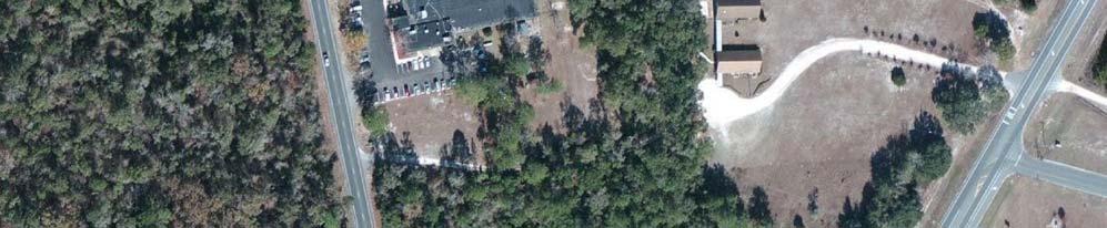
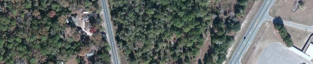
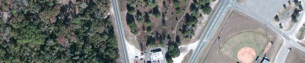
4 ROCKY S CONVENIENCE STORE DRAINAGE REPORT Page INTRODUCTION The proposed Rocky s Convenience store is located in Wakulla County, Florida and is on approximately 5.10-acres of land. The proposed Rocky s development is located south of Friendship Church Road and the Eden Springs Nursing home, east of Crawfordville Highway and north of US 98 and Wakulla High School. See attached Vicinity Map. The proposed project consists of constructing a 12,750 SF convenience store, associated fueling stations, 6,800 SF of future retail, and associated paved parking. 2.0 LAND USAGE / COVER The existing land use is vacant residential. The on-site natural land cover is primarily Herbaceous (Dry Prairie) Code 310, per the Florida Land Use Cover & Classification System, Level 3. The following is a table of the various project areas: Area of Parcel 222,156 sq.ft. Disturbed Area (Project Area) 222,156 sq.ft. Proposed Impervious Area 136,379 sq.ft. Ratio of Impervious Area to Disturbed Area % Weighted C Value PRDA-1 Weighted C Value PRDA Water Quality Retention Required for (SWMF 1) 8,831 CF Water Quality Retention Required for (SWMF 2) 3,177 CF 3.0 FLOODPLAIN INFORMATION The proposed development is contained within the FEMA FIRM map, 12129C 0360E, Wakulla County, Florida, (Effective Date September 26, 2014). The entire site is contained within Zone C areas of minimal flooding. FEMA has not determined the 10-year flooding limits for this area.

5 WAKULLA HIGH SCHOOL US 319 SITE US 98 VICINITY MAP
6 ROCKY S CONVENIENCE STORE DRAINAGE REPORT Page SOILS The soils type within the onsite and offsite drainage basin consists of: Alpin fine sands Map Unit 4 Otela Alpin fine sands Map Unit 47 Hydrologic Group: A Hydrologic Group: A The basin soil type is predominantly representative of Soils Group A in accordance with the National Resources Conservation Service (NRCS) soils classifications. These soils have a high infiltration rate when thoroughly wet. See Appendix A Soils Survey and Appendix B Geotechnical Report provided by Alpha Geotechnical and Testing Services, Inc. This site is located within a Sensitive Karst Area, per the NWFWMD. A geotechnical investigation was performed by Alpha Geotechnical and Testing Services, Inc. dated June 8, The borings did not encounter limestone bedrock or groundwater within 20 feet below the surface in the vicinity of the proposed retention facility. Per the geotechnical report, the seasonal high water table is anticipated at 8.8 feet below the existing grade for SWMF 1 and 9.5 feet below existing grade for SWMF 2. Per the geotechnical investigation, the saturated vertical infiltration rate in the area of the proposed SWMF 1 is 23.5 in/hr and 13.7 in/hr for SWMF 2. The saturated horizontal conductivity was recommended to be 1.5 time the saturated vertical conductivity.
7
8
9
10
11
12
13
14 ROCKY S CONVENIENCE STORE DRAINAGE REPORT Page HYDROLOGY / HYDRAULIC ANALYSIS A hydrologic analysis was performed on the study area to define the peak runoff flows and volumes for the 25-year, 24-hour design storm frequency. The peak flow information obtained from the analysis was used to evaluate existing drainage facilities and to design the proposed drainage improvements. The program ICPR3 w/percpak was used to determine runoff quantities for each basin. The basin parameters required for hydrologic input include: Area, Curve Number Slope Time of Concentration, Runoff coefficient for each land cover / usage, Precipitation. Appendix A provides the parameters used in the existing and proposed conditions in the ICPR3 model. The 25-year, 24-hour maximum rainfall amount for this site is 9.0 inches, per the FDEP Modified Technical Paper No. 40, Rainfall Frequency Atlas of the United States. 5.1 EXISTING FACILITIES Hydra Engineering and Construction, LLC performed a site visit in June 8, 2016 to determine the existing drainage patterns. The site drains to an existing offsite natural low in the north of the site. Offsite runoff from the FDOT R/W is captured in exiting ditches along US 98 and US 319. The existing drainage pattern is generally from south to north toward the existing offsite low area. The existing topography was prepared by Edwin Brown & Associates, Inc. on November 5, The topography was extended 100 feet off the project boundary. The contours are referenced to NAVD The curve number (CN) is based on the calculations from Michael Baker and Associates for existing conditions basins 3 and 4b provided in the Drainage Design Documentation for FPID # These values are 49.4 and 46.4 and were applied to The Rocky s convenience store existing conditions basins EXDA-1 and EXDA-2 accordingly.

15
16 ROCKY S CONVENIENCE STORE DRAINAGE REPORT Page PROPOSED DRAINAGE IMPROVEMENTS The proposed drainage patterns for the site will consist of sheet flow from the south and to the north and east across the site. The runoff from the proposed Rocky s convenience store will be directed toward storm drain inlets and associated closed pipe system. Discharge from the system will be into SWMF-1 and SWMF-2 respectively. These two retention facilities and connected by an equalizer pipe allowing them to function as one system. See calculations provided in Appendix A. Due to the proposed construction having greater than 50 percent impervious over the project area, Northwest Florida Water Management District requires the post-development peak discharge rate must not exceed the pre-development peak discharge rate for the 25-year, 24- hour design storm event. A water quality pond is proposed to attenuate the developed peak flows to existing peak flows and to treat 1 inch of runoff over the contributing area. The routing calculations were performed using ICPR3 w/percpack. The retention facilities have a bottom elevation of 30 with the top of the pond at 34 for SWMF-1 and 35 for SWMF-2. The water quality/treatment elevation is for SWMF-1 and for SWMF-2. In order to have a positive outfall the water quality weir elevation is set at for SWMF-1 and for SWMF-2. Based on the ICPR routing analysis, the 25 year 24-hour water surface elevation is at for SWMF-1 and for SWMF-2. The proposed online water quality dry retention volume requires 8,831 CF for SWMF-1 and 3,177 CF for SWMF-2 to treat the runoff from one inch of rainfall from the contributing area. Due to being in a Karst Sensitive area, the entire detention facility shall be sodded. The weighted runoff coefficient for the developed basin PRDA-1 is 0.62 and the runoff coefficient for the developed basin PRDA-2 is The developed composite curve numbers based on imperviousness and landscaped areas for PRDA-1 and PRDA-2 are and respectively. The outfall structure for SWMF-1 will be a slot for a 12 x12 rectangular weir with a grease skimmer placed at the east end of the retention facility. The outfall structure for SWMF-2 will be a slot for a 5 x12 rectangular weir with a grease skimmer placed at the east end of the retention facility. The weirs have been sized to reduce the developed peak flow to the historic peak flows. The overflow from the retention facilities will discharge through the proposed weirs to safely convey stormwater in excess of the 25-year storm away from the site. The receiving water for the site are the proposed FDOT drainage ditches located along the west side of the proposed Crawfordville Highway realignment. They are located from STA (L) to STA (L) and from STA (L) to (L) along the proposed realignment. Since the entire site is outside of a designated 100-year floodplain, flood protection measures are not necessary.
17 ROCKY S CONVENIENCE STORE DRAINAGE REPORT Page 11 Construction of the site also requires a driveway connection to the future US 319 realignment. The proposed driveway connection requires modifications to two FDOT curb inlets. The modifications change the structures from Type 1 and Type 2 curb inlets to Type V gutter inlets. Calculations demonstrating the proposed structure modifications meet or exceed the capture capacity of the original design are included in Appendix A.

18

19 US 319 SITE US ' 1000' SCALE 1"=500'
20 ROCKY S CONVENIENCE STORE DRAINAGE REPORT Page CONSTRUCTION SEQUENCE Implementation of this Stormwater Management Plan should be in place prior to commencing construction. The estimated start date for the grading operations is December Once the structural site management controls are in place, clearing and grubbing will commence within the disturbance limits. The installation of storm drainage facilities, will start after the clearing and grubbing, followed by installation of utilities, fine grading, paving, installation of landscaping and final stabilization of the site (seeding disturbed pervious areas), in that order. The silt fence shall be installed around the limits of construction and per the Erosion Control Plan prior to starting any construction activities. The storm drain outlet protection shall be installed and maintained once the storm drainage facilities are constructed. The proposed water quality pond facility will be protected from sediment using silt fencing around its perimeter; this will reduce the possibility of premature clogging and loss of infiltration capacity. The final site stabilization methods, such as landscaping and removing temporary erosion control structures are estimated to occur in January The anticipated completion date for the proposed project is July The storm water management sequence will be the installation of the perimeter sediment controls such as sediment control fences and straw rolls, and then the site construction will begin. Major soil disturbances will be seeded and mulched within seven (7) days after final grade is reached or if areas have been exposed and inactive for more than fourteen (14) days. The pervious areas disturbed during construction activities will be seeded at the completion of paving operations. The total acres of the site expected to undergo grading activities is 5.10 acres. Potential pollution sources include: equipment refueling and maintenance, grading operations and concrete wash water. No irrigation flows are anticipated to be combined with the stormwater system. 7.0 BEST MANAGEMENT PRACTICES (BMPs) The following describes the site management procedures that will be implemented at the Rocky s convenience store in accordance with Wakulla County and Northwest Florida Water Management District regulations. During construction activities and until vegetation can be established, sedimentation fences will be installed parallel to the top of banks, and check dams (staked straw bales) will be placed in the flow line of the roadside swale along US 98 and US 319, as shown on the Erosion Control plan. This should be sufficient to mitigate the sediment discharged into the existing ditch system.
21 ROCKY S CONVENIENCE STORE DRAINAGE REPORT Page 15 Sediment and mud shall be prevented from leaving the construction site by immediate placement of construction vehicle tracking control in all access routes. Vehicle tracking control shall be at least fifty (50) feet in length and comprised of angular rock. The contractor is responsible for cleaning and general upkeep of existing public roads used for access. The existing vegetation will be maintained where practical. Major soil disturbances will be seeded and mulched within seven (7) days after final grade is reached or if areas have been exposed and inactive for more than fourteen (14) days. In the interim condition, water trucks should be utilized onsite for the duration of the construction period to minimize potential construction dust uprising as an effective dust control measure. Good housekeeping BMPs should be followed throughout the entire life of the project. These include the following: - Refuse receptacles should be regularly emptied and equipped with lids. - Machinery should be kept in good operating condition to prevent leakage. - Apply appropriate (not excessive) amounts of fertilizer to the landscaping. - Schedule regular maintenance of BMPs and cleaning of storm drains, grates and inlets - Portable toilet facility on-site. Other housekeeping practices should include general site cleanliness and proper training of employees. Per NWFWMD regulations, site inspections shall be performed by a qualified inspector that has successfully completed the Department s Stormwater, Erosion, and Sedimentation Control Inspector Training Program, or an equivalent program. The site inspections must include, all points of discharge into surface water of the State or an MS4; disturbed areas of the construction site that have not been finally stabilized; areas used for storage of materials that are exposed to precipitation; structural controls; and, location where vehicles enter or exit the site, at least once every seven calendar days and within 24 hours of the end of a storm that is 0.5 inches or greater (NWFWMD, Section ). The inspection reports will be required to be kept with this Stormwater Management Plan to be included with the compliance certification report at the end of the project. Once the construction activities are complete and the site is stabilized, the land owner is financially responsible for the operation and maintenance of the surface water management system for a period of 10 years. The owner of the property will be responsible for contracting services to operate and perform routine custodial maintenance of the surface water management system. Inspections of the permitted system during the operation phase shall be conducted annually due to the site being located in a karst sensitive area.
22 ROCKY S CONVENIENCE STORE DRAINAGE REPORT Page MATERIAL HANDLING AND SPILL PREVENTION No chemicals, fuels, or other materials are anticipated to be stored on site. If fuel or oil for construction machinery is present on the site, materials should be stored and handled in covered areas to prevent contact with stormwater, and chemicals should be stored within berms or secondary containment devices to prevent leaks and spills from entering stormwater runoff. Cleaning and fueling of machinery should be done during dry weather, if possible. Washing of concrete trucks and other equipment into the storm drainage system is prohibited. Spills or accidents shall be immediately reported to the SWMP Administrator and depending on the nature of the spill involved, the Environmental Protection Agency, downstream users, or other agencies may need to be notified.
23 ROCKY S CONVENIENCE STORE DRAINAGE REPORT Page REFERENCES 1. Soil Survey of Wakulla County, Florida, U.S. Department of Agriculture, Soil Conservation Service, Northwest Florida Water Management District Environmental Resource Permit Applicant s Handbook Volume II, October 1, FDEP Modified Technical Paper No. 40, Rainfall Frequency Atlas of the United States. 4. Subsurface Exploration and Foundation Evaluation for Rocky s Gas Station, Alpha Geotechnical and Testing Services, Inc. report dated June 8, 2016.
24 ROCKY S CONVENIENCE STORE DRAINAGE REPORT Page 18 APPENDIX A HYDROLOGY / HYDRAULIC CALCULATIONS
25 PRE DEVELOPMENT CURVE NUMBER Basin Area (AC) CN EXDA EXDA ROCKY'S CONVENIENCE STORE RUNOFF CALCULATIONS Predevelopment CN values utilize those provided in the Drainage Design Documentation prepared by Michael Baker and Associates for FPID # POST DEVELOPMENT CURVE NUMBER Basin Impervious Area (SF) CN Pervious Area CN CN Total Area (SF) (SF) (Weighted) PRDA 1 98, , , PRDA 2 37, , , POST DEVELOPMENT RUNOFF COEFFICIENTS Basin Impervious Area (SF) C Pervious Area (SF) C Total Area (SF) C (Weighted) PRDA 1 98, , , PRDA 2 37, , , SWMF 1 Treatment Volume 0.5" of runoff over the contributing area= 7,111 CF 1" of rain over contributing area= 8,831 CF Use larger of the two calculations therefore Treatment Volume= 8,831 CF SWMF 2 Treatment Volume 0.5" of runoff over the contributing area= 2,135 CF 1" of rain over contributing area= 3,177 CF Use larger of the two calculations therefore Treatment Volume= 3,177 CF
26 U.S. Department of Agriculture FL-ENG-21B Natural Resources Conservation Service 04/04 06/04 TR 55 Worksheet 3: Time of Concentration (T c ) or Travel Time (T t ) Project: Rocky's Gas Station Designed By: MTZ Date: 8/8/16 Location: Wakulla County, FL Checked By: LAH Date: 8/8/16 Check Circle one: Present Developed Check Circle one: T c T t through subarea EX-DA1 NOTES: Space for as many as two segments per flow type can be used for each worksheet. Include a map, schematic, or description of flow segments. Sheet Flow (Applicable to T c only) Segment ID 1 1. Surface description (Table 3-1) Manning s roughness coeff., n (Table 3-1) Flow length, L (total L < 100 ft)... ft 4. Two-year 24-hour rainfall, P 2... in 5. Land slope, s... ft/ft Wooded LT T t = (nl) 0.8 Compute T t... hr = 0.38 P s 0.4 Shallow Concetrated Flow Segment ID 2 7. Surface description (paved or unpaved) Flow length, L... ft 9. Watercourse slope, s... ft/ft 10. Average velocity, V (Figure 3-1)... ft/s Unpaved T t = L Compute T t... hr = V Channel Flow Segment ID 12. Cross sectional flow area, a... ft Wetted perimeter, P w... ft 14. Hydraulic radius, r = a Compute r... ft P w 15. Channel Slope, s... ft/ft 16. Manning s Roughness Coeff., n V = 1.49 r 2/3 s 1/2 Compute V... ft/s n 18. Flow length, L... ft 19. T t = L Compute T t... hr + = 3600 V 20. Watershed or subarea T c or T t (add T t in steps 6, 11, and hr 0.47
27 U.S. Department of Agriculture FL-ENG-21B Natural Resources Conservation Service 04/04 06/04 TR 55 Worksheet 3: Time of Concentration (T c ) or Travel Time (T t ) Project: Rocky's Gas Station Designed By: MTZ Date: 8/8/16 Location: Wakulla County, FL Checked By: LAH Date: 8/8/16 Check Circle one: Present Developed Check Circle one: T c T t through subarea EX-DA2 NOTES: Space for as many as two segments per flow type can be used for each worksheet. Include a map, schematic, or description of flow segments. Sheet Flow (Applicable to T c only) Segment ID 1 1. Surface description (Table 3-1) Manning s roughness coeff., n (Table 3-1) Flow length, L (total L < 100 ft)... ft 4. Two-year 24-hour rainfall, P 2... in 5. Land slope, s... ft/ft Wooded LT T t = (nl) 0.8 Compute T t... hr = 0.32 P s 0.4 Shallow Concetrated Flow Segment ID 2 7. Surface description (paved or unpaved) Flow length, L... ft 9. Watercourse slope, s... ft/ft 10. Average velocity, V (Figure 3-1)... ft/s Unpaved T t = L Compute T t... hr = V Channel Flow Segment ID 12. Cross sectional flow area, a... ft Wetted perimeter, P w... ft 14. Hydraulic radius, r = a Compute r... ft P w 15. Channel Slope, s... ft/ft 16. Manning s Roughness Coeff., n V = 1.49 r 2/3 s 1/2 Compute V... ft/s n 18. Flow length, L... ft 19. T t = L Compute T t... hr + = 3600 V 20. Watershed or subarea T c or T t (add T t in steps 6, 11, and hr 0.40
28 U.S. Department of Agriculture FL-ENG-21B Natural Resources Conservation Service 04/04 06/04 TR 55 Worksheet 3: Time of Concentration (T c ) or Travel Time (T t ) Project: Rocky's Gas Station Designed By: MTZ Date: 8/8/16 Location: Wakulla County, FL Checked By: LAH Date: 8/8/16 Check Circle one: Present Developed Check Circle one: T c T t through subarea PR-DA1 NOTES: Space for as many as two segments per flow type can be used for each worksheet. Include a map, schematic, or description of flow segments. Sheet Flow (Applicable to T c only) Segment ID 1 1. Surface description (Table 3-1) Manning s roughness coeff., n (Table 3-1) Flow length, L (total L < 100 ft)... ft 4. Two-year 24-hour rainfall, P 2... in 5. Land slope, s... ft/ft GRASS T t = (nl) 0.8 Compute T t... hr = 0.25 P s 0.4 Shallow Concetrated Flow Segment ID 2 7. Surface description (paved or unpaved) Flow length, L... ft 9. Watercourse slope, s... ft/ft 10. Average velocity, V (Figure 3-1)... ft/s UNPAVED T t = L Compute T t... hr = V Channel Flow Segment ID 12. Cross sectional flow area, a... ft Wetted perimeter, P w... ft 14. Hydraulic radius, r = a Compute r... ft P w 15. Channel Slope, s... ft/ft 16. Manning s Roughness Coeff., n V = 1.49 r 2/3 s 1/2 Compute V... ft/s n 18. Flow length, L... ft 19. T t = L Compute T t... hr + = 3600 V 20. Watershed or subarea T c or T t (add T t in steps 6, 11, and hr 0.34
29 U.S. Department of Agriculture FL-ENG-21B Natural Resources Conservation Service 04/04 06/04 TR 55 Worksheet 3: Time of Concentration (T c ) or Travel Time (T t ) Project: Rocky's Gas Station Designed By: MTZ Date: 8/8/16 Location: Wakulla County, FL Checked By: LAH Date: 8/8/16 Check Circle one: Present Developed Check Circle one: T c T t through subarea PR-DA2 NOTES: Space for as many as two segments per flow type can be used for each worksheet. Include a map, schematic, or description of flow segments. Sheet Flow (Applicable to T c only) Segment ID 1 1. Surface description (Table 3-1) Manning s roughness coeff., n (Table 3-1) Flow length, L (total L < 100 ft)... ft 4. Two-year 24-hour rainfall, P 2... in 5. Land slope, s... ft/ft Grass T t = (nl) 0.8 Compute T t... hr = 0.33 P s 0.4 Shallow Concetrated Flow Segment ID 2 7. Surface description (paved or unpaved) Flow length, L... ft 9. Watercourse slope, s... ft/ft 10. Average velocity, V (Figure 3-1)... ft/s UNPAVED T t = L Compute T t... hr = V Channel Flow Segment ID 12. Cross sectional flow area, a... ft Wetted perimeter, P w... ft 14. Hydraulic radius, r = a Compute r... ft P w 15. Channel Slope, s... ft/ft 16. Manning s Roughness Coeff., n V = 1.49 r 2/3 s 1/2 Compute V... ft/s n 18. Flow length, L... ft 19. T t = L Compute T t... hr + = 3600 V 20. Watershed or subarea T c or T t (add T t in steps 6, 11, and hr 0.35
30 Stormwater Management Facility Volume Rocky's Gas Station Hydra Job Number: /8/2016 SWMF 1 ELEVATION AREA Area (AC) VOLUME (Ft 3 ) CUMULATIVE VOLUME (Ft 3 ) CUMULATIVE VOLUME (ac/ft) , , , , , , , , , , , , , Total SWMF Volume (AF): Treatment Volume= 8,831.0 c.f ac ft Pond Elev.= ft
31 Stormwater Management Facility Volume Rocky's Gas Station Hydra Job Number: /8/2016 SWMF 2 ELEVATION AREA Area (AC) VOLUME (Ft 3 ) CUMULATIVE VOLUME (Ft 3 ) CUMULATIVE VOLUME (ac/ft) , , , , , , , , , , Total SWMF Volume (AF): Treatment Vol. = Pond Elev. = 3,177.0 c.f ac ft ft
32 Nodal Network Diagram Nodes A Stage/Area V Stage/Volume T Time/Stage M Manhole Basins O Overland Flow U SCS Unit CN S SBUH CN Y SCS Unit GA Z SBUH GA T: PR-BNDY-1 W:Outfall 1 T:Ground 1 E:Perc 1 P:S-150,SWMF 1 T:Ground 2 E:Perc 2 T: PR-BNDY-2 W:Outfall 2 Links P Pipe W Weir C Channel D Drop Structure B Bridge R Rating Curve H Breach E Percolation F Filter X Exfil Trench C:Channel 1 A: PR-DA1 U: PR-DA1 A: SWMF 1 A: S-150 T:EX. BNDY-1 P:S-150,SWMF 2 T:EX. BNDY-2 A:SWMF 2 C:Channel 2 A: PR-DA2 U: PR-DA2 C: EX-OVERFLOW-1 C: EX-OVERFLOW-2 A: EX-DA1 A: EX-DA2 U: EX-DA1 U: EX-DA2 Interconnected Channel and Pond Routing Model (ICPR) 2002 Streamline Technologies, Inc.
33 Complete Input Report ========================================================================================== ==== Basins ============================================================================== ========================================================================================== Name: EX-DA1 Node: EX-DA1 Status: Onsite Group: BASE Type: SCS Unit Hydrograph CN Unit Hydrograph: Uh323 Peaking Factor: Rainfall File: Storm Duration(hrs): Rainfall Amount(in): Time of Conc(min): Area(ac): 2.41 Time Shift(hrs): 0.00 Curve Number: Max Allowable Q(cfs): DCIA(%): 0.00 Name: EX-DA2 Node: EX-DA2 Status: Onsite Group: BASE Type: SCS Unit Hydrograph CN Unit Hydrograph: Uh323 Peaking Factor: Rainfall File: Storm Duration(hrs): Rainfall Amount(in): Time of Conc(min): Area(ac): 2.68 Time Shift(hrs): 0.00 Curve Number: Max Allowable Q(cfs): DCIA(%): 0.00 Name: PR-DA1 Node: PR-DA1 Status: Onsite Group: BASE Type: SCS Unit Hydrograph CN Unit Hydrograph: Uh323 Peaking Factor: Rainfall File: Storm Duration(hrs): Rainfall Amount(in): Time of Conc(min): Area(ac): 3.92 Time Shift(hrs): 0.00 Curve Number: Max Allowable Q(cfs): DCIA(%): 0.00 Name: PR-DA2 Node: PR-DA2 Status: Onsite Group: BASE Type: SCS Unit Hydrograph CN Unit Hydrograph: Uh323 Peaking Factor: Rainfall File: Storm Duration(hrs): Rainfall Amount(in): Time of Conc(min): Area(ac): 1.18 Time Shift(hrs): 0.00 Curve Number: Max Allowable Q(cfs): DCIA(%): 0.00 ========================================================================================== ==== Nodes =============================================================================== ========================================================================================== Name: EX-DA1 Base Flow(cfs): Init Stage(ft): Interconnected Channel and Pond Routing Model (ICPR) 2002 Streamline Technologies, Inc. Page 1 of 35
34 Complete Input Report Group: BASE Warn Stage(ft): Type: Stage/Area Stage(ft) Area(ac) Name: EX-DA2 Base Flow(cfs): Init Stage(ft): Group: BASE Warn Stage(ft): Type: Stage/Area Stage(ft) Area(ac) Name: EX. BNDY-1 Base Flow(cfs): Init Stage(ft): Group: BASE Warn Stage(ft): Type: Time/Stage Time(hrs) Stage(ft) Name: EX. BNDY-2 Base Flow(cfs): Init Stage(ft): Group: BASE Warn Stage(ft): Type: Time/Stage Time(hrs) Stage(ft) Name: Ground 1 Base Flow(cfs): Init Stage(ft): Group: BASE Warn Stage(ft): Type: Time/Stage Time(hrs) Stage(ft) Name: Ground 2 Base Flow(cfs): Init Stage(ft): Group: BASE Warn Stage(ft): Type: Time/Stage Interconnected Channel and Pond Routing Model (ICPR) 2002 Streamline Technologies, Inc. Page 2 of 35
35 Complete Input Report Time(hrs) Stage(ft) Name: PR-BNDY-1 Base Flow(cfs): Init Stage(ft): Group: BASE Warn Stage(ft): Type: Time/Stage Time(hrs) Stage(ft) Name: PR-BNDY-2 Base Flow(cfs): Init Stage(ft): Group: BASE Warn Stage(ft): Type: Time/Stage Time(hrs) Stage(ft) Name: PR-DA1 Base Flow(cfs): Init Stage(ft): Group: BASE Warn Stage(ft): Type: Stage/Area Stage(ft) Area(ac) Name: PR-DA2 Base Flow(cfs): Init Stage(ft): Group: BASE Warn Stage(ft): Type: Stage/Area Stage(ft) Area(ac) Name: S-150 Base Flow(cfs): Init Stage(ft): Group: BASE Warn Stage(ft): Type: Stage/Area Stage(ft) Area(ac) Interconnected Channel and Pond Routing Model (ICPR) 2002 Streamline Technologies, Inc. Page 3 of 35
36 Complete Input Report Name: SWMF 1 Base Flow(cfs): Init Stage(ft): Group: BASE Warn Stage(ft): Type: Stage/Area Stage(ft) Area(ac) Name: SWMF 2 Base Flow(cfs): Init Stage(ft): Group: BASE Warn Stage(ft): Type: Stage/Area Stage(ft) Area(ac) ========================================================================================== ==== Operating Tables ==================================================================== ========================================================================================== Name: Group: BASE Type: Bottom Clip Function: Time vs. Depth of Clip Time(hrs) Clip Depth(in) ========================================================================================== ==== Pipes =============================================================================== ========================================================================================== Name: S-150,SWMF 1 From Node: S-150 Length(ft): Group: BASE To Node: SWMF 1 Count: 1 Friction Equation: Average Conveyance UPSTREAM DOWNSTREAM Solution Algorithm: Most Restrictive Geometry: Circular Circular Flow: Both Span(in): Entrance Loss Coef: 0.20 Rise(in): Exit Loss Coef: 1.00 Invert(ft): Bend Loss Coef: 0.00 Manning's N: Outlet Ctrl Spec: Use dc or tw Top Clip(in): Inlet Ctrl Spec: Use dc Bot Clip(in): Stabilizer Option: None Interconnected Channel and Pond Routing Model (ICPR) 2002 Streamline Technologies, Inc. Page 4 of 35
37 Complete Input Report Upstream FHWA Inlet Edge Description: Circular Concrete: Square edge w/ headwall Downstream FHWA Inlet Edge Description: Circular Concrete: Square edge w/ headwall Name: S-150,SWMF 2 From Node: S-150 Length(ft): Group: BASE To Node: SWMF 2 Count: 1 Friction Equation: Average Conveyance UPSTREAM DOWNSTREAM Solution Algorithm: Most Restrictive Geometry: Circular Circular Flow: Both Span(in): Entrance Loss Coef: 0.00 Rise(in): Exit Loss Coef: 1.00 Invert(ft): Bend Loss Coef: 0.00 Manning's N: Outlet Ctrl Spec: Use dc or tw Top Clip(in): Inlet Ctrl Spec: Use dc Bot Clip(in): Stabilizer Option: None Upstream FHWA Inlet Edge Description: Circular Concrete: Square edge w/ headwall Downstream FHWA Inlet Edge Description: Circular Concrete: Square edge w/ headwall ========================================================================================== ==== Channels ============================================================================ ========================================================================================== Name: Channel 1 From Node: PR-DA1 Length(ft): Group: BASE To Node: SWMF 1 Count: 1 UPSTREAM DOWNSTREAM Friction Equation: Average Conveyance Geometry: Trapezoidal Trapezoidal Solution Algorithm: Automatic Invert(ft): Flow: Both TClpInitZ(ft): Contraction Coef: Manning's N: Expansion Coef: Top Clip(ft): Entrance Loss Coef: Bot Clip(ft): Exit Loss Coef: Main XSec: Outlet Ctrl Spec: Use dn or tw AuxElev1(ft): Inlet Ctrl Spec: Use dn Aux XSec1: Stabilizer Option: None AuxElev2(ft): Aux XSec2: Top Width(ft): Depth(ft): Bot Width(ft): LtSdSlp(h/v): RtSdSlp(h/v): Name: Channel 2 From Node: PR-DA2 Length(ft): Interconnected Channel and Pond Routing Model (ICPR) 2002 Streamline Technologies, Inc. Page 5 of 35
38 Complete Input Report Group: BASE To Node: SWMF 2 Count: 1 UPSTREAM DOWNSTREAM Friction Equation: Average Conveyance Geometry: Trapezoidal Trapezoidal Solution Algorithm: Automatic Invert(ft): Flow: Both TClpInitZ(ft): Contraction Coef: Manning's N: Expansion Coef: Top Clip(ft): Entrance Loss Coef: Bot Clip(ft): Exit Loss Coef: Main XSec: Outlet Ctrl Spec: Use dn or tw AuxElev1(ft): Inlet Ctrl Spec: Use dn Aux XSec1: Stabilizer Option: None AuxElev2(ft): Aux XSec2: Top Width(ft): Depth(ft): Bot Width(ft): LtSdSlp(h/v): RtSdSlp(h/v): Name: EX-OVERFLOW-1 From Node: EX-DA1 Length(ft): Group: BASE To Node: EX. BNDY-1 Count: 1 UPSTREAM DOWNSTREAM Friction Equation: Average Conveyance Geometry: Trapezoidal Trapezoidal Solution Algorithm: Automatic Invert(ft): Flow: Both TClpInitZ(ft): Contraction Coef: Manning's N: Expansion Coef: Top Clip(ft): Entrance Loss Coef: Bot Clip(ft): Exit Loss Coef: Main XSec: Outlet Ctrl Spec: Use dn or tw AuxElev1(ft): Inlet Ctrl Spec: Use dn Aux XSec1: Stabilizer Option: None AuxElev2(ft): Aux XSec2: Top Width(ft): Depth(ft): Bot Width(ft): LtSdSlp(h/v): RtSdSlp(h/v): Name: EX-OVERFLOW-2 From Node: EX-DA2 Length(ft): Group: BASE To Node: EX. BNDY-2 Count: 1 UPSTREAM DOWNSTREAM Friction Equation: Average Conveyance Geometry: Trapezoidal Trapezoidal Solution Algorithm: Automatic Invert(ft): Flow: Both TClpInitZ(ft): Contraction Coef: Manning's N: Expansion Coef: Top Clip(ft): Entrance Loss Coef: Bot Clip(ft): Exit Loss Coef: Main XSec: Outlet Ctrl Spec: Use dn or tw AuxElev1(ft): Inlet Ctrl Spec: Use dn Aux XSec1: Stabilizer Option: None AuxElev2(ft): Interconnected Channel and Pond Routing Model (ICPR) 2002 Streamline Technologies, Inc. Page 6 of 35
39 Complete Input Report Aux XSec2: Top Width(ft): Depth(ft): Bot Width(ft): LtSdSlp(h/v): RtSdSlp(h/v): ========================================================================================== ==== Weirs =============================================================================== ========================================================================================== Name: Outfall 1 From Node: SWMF 1 Group: BASE To Node: PR-BNDY-1 Flow: Both Count: 1 Type: Vertical: Fread Geometry: Rectangular Span(in): Rise(in): Invert(ft): Control Elevation(ft): Bottom Clip(in): Top Clip(in): Weir Discharge Coef: Orifice Discharge Coef: TABLE Name: Outfall 2 From Node: SWMF 2 Group: BASE To Node: PR-BNDY-2 Flow: Both Count: 1 Type: Vertical: Fread Geometry: Rectangular Span(in): Rise(in): 5.00 Invert(ft): Control Elevation(ft): Bottom Clip(in): Top Clip(in): Weir Discharge Coef: Orifice Discharge Coef: TABLE ========================================================================================== ==== Percolation Links =================================================================== ========================================================================================== Name: Perc 1 From Node: SWMF 1 Flow: Both Group: BASE To Node: Ground 1 Count: 1 Surface Area Option: Vary based on Stage/Area Table Vertical Flow Termination: Horizontal Flow Algorithm Aquifer Base Elev(ft): Perimeter 1(ft): Water Table Elev(ft): Perimeter 2(ft): Ann Recharge Rate(in/year): Perimeter 3(ft): Horiz Conductivity(ft/day): Distance 1 to 2(ft): Interconnected Channel and Pond Routing Model (ICPR) 2002 Streamline Technologies, Inc. Page 7 of 35
40 Complete Input Report Vert Conductivity(ft/day): Distance 2 to 3(ft): Effective Porosity(dec): Num Cells 1 to 2: 10 Suction Head(in): Num Cells 2 to 3: 45 Layer Thickness(ft): Name: Perc 2 From Node: SWMF 2 Flow: Both Group: BASE To Node: Ground 2 Count: 1 Surface Area Option: Vary based on Stage/Area Table Vertical Flow Termination: Horizontal Flow Algorithm Aquifer Base Elev(ft): Perimeter 1(ft): Water Table Elev(ft): Perimeter 2(ft): Ann Recharge Rate(in/year): Perimeter 3(ft): Horiz Conductivity(ft/day): Distance 1 to 2(ft): Vert Conductivity(ft/day): Distance 2 to 3(ft): Effective Porosity(dec): Num Cells 1 to 2: 10 Suction Head(in): Num Cells 2 to 3: 45 Layer Thickness(ft): ========================================================================================== ==== Hydrology Simulations =============================================================== ========================================================================================== Name: 002Y001H Filename: J:\Projects\2015\131-Rocky's Convenience Store\ICPR\SWMF\002Y001H.R32 Override Defaults: Yes Storm Duration(hrs): 1.00 Rainfall File: FDOT-1 Rainfall Amount(in): Name: 002Y002H Filename: J:\Projects\2015\131-Rocky's Convenience Store\ICPR\SWMF\002Y002H.R32 Override Defaults: Yes Storm Duration(hrs): 2.00 Rainfall File: FDOT-2 Rainfall Amount(in): Name: 002Y004H Filename: J:\Projects\2015\131-Rocky's Convenience Store\ICPR\SWMF\002Y004H.R32 Override Defaults: Yes Storm Duration(hrs): 4.00 Interconnected Channel and Pond Routing Model (ICPR) 2002 Streamline Technologies, Inc. Page 8 of 35
41 Complete Input Report Rainfall File: FDOT-4 Rainfall Amount(in): Name: 002Y008H Filename: J:\Projects\2015\131-Rocky's Convenience Store\ICPR\SWMF\002Y008H.R32 Override Defaults: Yes Storm Duration(hrs): 8.00 Rainfall File: FDOT-8 Rainfall Amount(in): Name: 002Y024H Filename: J:\Projects\2015\131-Rocky's Convenience Store\ICPR\SWMF\002Y024H.R32 Override Defaults: Yes Storm Duration(hrs): Rainfall File: FDOT-24 Rainfall Amount(in): Name: 002Y072H Filename: J:\Projects\2015\131-Rocky's Convenience Store\ICPR\SWMF\002Y072H.R32 Override Defaults: Yes Storm Duration(hrs): Rainfall File: FDOT-72 Rainfall Amount(in): Name: 003Y001H Filename: J:\Projects\2015\131-Rocky's Convenience Store\ICPR\SWMF\003Y001H.R32 Override Defaults: Yes Storm Duration(hrs): 1.00 Rainfall File: FDOT-1 Rainfall Amount(in): Name: 003Y002H Interconnected Channel and Pond Routing Model (ICPR) 2002 Streamline Technologies, Inc. Page 9 of 35
42 Complete Input Report Filename: J:\Projects\2015\131-Rocky's Convenience Store\ICPR\SWMF\003Y002H.R32 Override Defaults: Yes Storm Duration(hrs): 2.00 Rainfall File: FDOT-2 Rainfall Amount(in): Name: 003Y004H Filename: J:\Projects\2015\131-Rocky's Convenience Store\ICPR\SWMF\003Y004H.R32 Override Defaults: Yes Storm Duration(hrs): 4.00 Rainfall File: FDOT-4 Rainfall Amount(in): Name: 003Y008H Filename: J:\Projects\2015\131-Rocky's Convenience Store\ICPR\SWMF\003Y008H.R32 Override Defaults: Yes Storm Duration(hrs): 8.00 Rainfall File: FDOT-8 Rainfall Amount(in): Name: 003Y024H Filename: J:\Projects\2015\131-Rocky's Convenience Store\ICPR\SWMF\003Y024H.R32 Override Defaults: Yes Storm Duration(hrs): Rainfall File: FDOT-24 Rainfall Amount(in): Name: 003Y072H Filename: J:\Projects\2015\131-Rocky's Convenience Store\ICPR\SWMF\003Y072H.R32 Override Defaults: Yes Storm Duration(hrs): Rainfall File: FDOT-72 Rainfall Amount(in): 7.05 Interconnected Channel and Pond Routing Model (ICPR) 2002 Streamline Technologies, Inc. Page 10 of 35
43 Complete Input Report Name: 005Y001H Filename: J:\Projects\2015\131-Rocky's Convenience Store\ICPR\SWMF\005Y001H.R32 Override Defaults: Yes Storm Duration(hrs): 1.00 Rainfall File: FDOT-1 Rainfall Amount(in): Name: 005Y002H Filename: J:\Projects\2015\131-Rocky's Convenience Store\ICPR\SWMF\005Y002H.R32 Override Defaults: Yes Storm Duration(hrs): 2.00 Rainfall File: FDOT-2 Rainfall Amount(in): Name: 005Y004H Filename: J:\Projects\2015\131-Rocky's Convenience Store\ICPR\SWMF\005Y004H.R32 Override Defaults: Yes Storm Duration(hrs): 4.00 Rainfall File: FDOT-4 Rainfall Amount(in): Name: 005Y008H Filename: J:\Projects\2015\131-Rocky's Convenience Store\ICPR\SWMF\005Y008H.R32 Override Defaults: Yes Storm Duration(hrs): 8.00 Rainfall File: FDOT-8 Rainfall Amount(in): Name: 005Y024H Filename: J:\Projects\2015\131-Rocky's Convenience Store\ICPR\SWMF\005Y024H.R32 Override Defaults: Yes Storm Duration(hrs): Rainfall File: FDOT-24 Interconnected Channel and Pond Routing Model (ICPR) 2002 Streamline Technologies, Inc. Page 11 of 35
44 Complete Input Report Rainfall Amount(in): Name: 005Y072H Filename: J:\Projects\2015\131-Rocky's Convenience Store\ICPR\SWMF\005Y072H.R32 Override Defaults: Yes Storm Duration(hrs): Rainfall File: FDOT-72 Rainfall Amount(in): Name: 010Y001H Filename: J:\Projects\2015\131-Rocky's Convenience Store\ICPR\SWMF\010Y001H.R32 Override Defaults: Yes Storm Duration(hrs): 1.00 Rainfall File: FDOT-1 Rainfall Amount(in): Name: 010Y002H Filename: J:\Projects\2015\131-Rocky's Convenience Store\ICPR\SWMF\010Y002H.R32 Override Defaults: Yes Storm Duration(hrs): 2.00 Rainfall File: FDOT-2 Rainfall Amount(in): Name: 010Y004H Filename: J:\Projects\2015\131-Rocky's Convenience Store\ICPR\SWMF\010Y004H.R32 Override Defaults: Yes Storm Duration(hrs): 4.00 Rainfall File: FDOT-4 Rainfall Amount(in): Name: 010Y008H Filename: J:\Projects\2015\131-Rocky's Convenience Store\ICPR\SWMF\010Y008H.R32 Interconnected Channel and Pond Routing Model (ICPR) 2002 Streamline Technologies, Inc. Page 12 of 35
45 Complete Input Report Override Defaults: Yes Storm Duration(hrs): 8.00 Rainfall File: FDOT-8 Rainfall Amount(in): Name: 010Y024H Filename: J:\Projects\2015\131-Rocky's Convenience Store\ICPR\SWMF\010Y024H.R32 Override Defaults: Yes Storm Duration(hrs): Rainfall File: FDOT-24 Rainfall Amount(in): Name: 010Y072H Filename: J:\Projects\2015\131-Rocky's Convenience Store\ICPR\SWMF\010Y072H.R32 Override Defaults: Yes Storm Duration(hrs): Rainfall File: FDOT-72 Rainfall Amount(in): Name: 025Y001H Filename: J:\Projects\2015\131-Rocky's Convenience Store\ICPR\SWMF\025Y001H.R32 Override Defaults: Yes Storm Duration(hrs): 1.00 Rainfall File: FDOT-1 Rainfall Amount(in): Name: 025Y002H Filename: J:\Projects\2015\131-Rocky's Convenience Store\ICPR\SWMF\025Y002H.R32 Override Defaults: Yes Storm Duration(hrs): 2.00 Rainfall File: FDOT-2 Rainfall Amount(in): Interconnected Channel and Pond Routing Model (ICPR) 2002 Streamline Technologies, Inc. Page 13 of 35
46 Complete Input Report Name: 025Y004H Filename: J:\Projects\2015\131-Rocky's Convenience Store\ICPR\SWMF\025Y004H.R32 Override Defaults: Yes Storm Duration(hrs): 4.00 Rainfall File: FDOT-4 Rainfall Amount(in): Name: 025Y008H Filename: J:\Projects\2015\131-Rocky's Convenience Store\ICPR\SWMF\025Y008H.R32 Override Defaults: Yes Storm Duration(hrs): 8.00 Rainfall File: FDOT-8 Rainfall Amount(in): Name: 025Y024H Filename: J:\Projects\2015\131-Rocky's Convenience Store\ICPR\SWMF\025Y024H.R32 Override Defaults: Yes Storm Duration(hrs): Rainfall File: FDOT-24 Rainfall Amount(in): Name: 025Y072H Filename: J:\Projects\2015\131-Rocky's Convenience Store\ICPR\SWMF\025Y072H.R32 Override Defaults: Yes Storm Duration(hrs): Rainfall File: FDOT-72 Rainfall Amount(in): Name: 050Y001H Filename: J:\Projects\2015\131-Rocky's Convenience Store\ICPR\SWMF\050Y001H.R32 Override Defaults: Yes Storm Duration(hrs): 1.00 Rainfall File: FDOT-1 Rainfall Amount(in): 4.00 Interconnected Channel and Pond Routing Model (ICPR) 2002 Streamline Technologies, Inc. Page 14 of 35
47 Complete Input Report Name: 050Y002H Filename: J:\Projects\2015\131-Rocky's Convenience Store\ICPR\SWMF\050Y002H.R32 Override Defaults: Yes Storm Duration(hrs): 2.00 Rainfall File: FDOT-2 Rainfall Amount(in): Name: 050Y004H Filename: J:\Projects\2015\131-Rocky's Convenience Store\ICPR\SWMF\050Y004H.R32 Override Defaults: Yes Storm Duration(hrs): 4.00 Rainfall File: FDOT-4 Rainfall Amount(in): Name: 050Y008H Filename: J:\Projects\2015\131-Rocky's Convenience Store\ICPR\SWMF\050Y008H.R32 Override Defaults: Yes Storm Duration(hrs): 8.00 Rainfall File: FDOT-8 Rainfall Amount(in): Name: 050Y024H Filename: J:\Projects\2015\131-Rocky's Convenience Store\ICPR\SWMF\050Y024H.R32 Override Defaults: Yes Storm Duration(hrs): Rainfall File: FDOT-24 Rainfall Amount(in): Name: 050Y072H Filename: J:\Projects\2015\131-Rocky's Convenience Store\ICPR\SWMF\050Y072H.R32 Interconnected Channel and Pond Routing Model (ICPR) 2002 Streamline Technologies, Inc. Page 15 of 35
48 Complete Input Report Override Defaults: Yes Storm Duration(hrs): Rainfall File: FDOT-72 Rainfall Amount(in): Name: 100Y001H Filename: J:\Projects\2015\131-Rocky's Convenience Store\ICPR\SWMF\100Y001H.R32 Override Defaults: Yes Storm Duration(hrs): 1.00 Rainfall File: FDOT-1 Rainfall Amount(in): Name: 100Y002H Filename: J:\Projects\2015\131-Rocky's Convenience Store\ICPR\SWMF\100Y002H.R32 Override Defaults: Yes Storm Duration(hrs): 2.00 Rainfall File: FDOT-2 Rainfall Amount(in): Name: 100Y004H Filename: J:\Projects\2015\131-Rocky's Convenience Store\ICPR\SWMF\100Y004H.R32 Override Defaults: Yes Storm Duration(hrs): 4.00 Rainfall File: FDOT-4 Rainfall Amount(in): Name: 100Y008H Filename: J:\Projects\2015\131-Rocky's Convenience Store\ICPR\SWMF\100Y008H.R32 Override Defaults: Yes Storm Duration(hrs): 8.00 Rainfall File: FDOT-8 Rainfall Amount(in): Interconnected Channel and Pond Routing Model (ICPR) 2002 Streamline Technologies, Inc. Page 16 of 35
49 Complete Input Report Name: 100Y024H Filename: J:\Projects\2015\131-Rocky's Convenience Store\ICPR\SWMF\100Y024H.R32 Override Defaults: Yes Storm Duration(hrs): Rainfall File: FDOT-24 Rainfall Amount(in): Name: 100Y072H Filename: J:\Projects\2015\131-Rocky's Convenience Store\ICPR\SWMF\100Y072H.R32 Override Defaults: Yes Storm Duration(hrs): Rainfall File: FDOT-72 Rainfall Amount(in): Name: WMD 25YR24HR Filename: J:\Projects\2015\131-Rocky's Convenience Store\ICPR\SWMF\WMD 25YR24HR.R32 Override Defaults: Yes Storm Duration(hrs): Rainfall File: Scsii-24 Rainfall Amount(in): Name: WMD 2YR24HR Filename: J:\Projects\2015\131-Rocky's Convenience Store\ICPR\SWMF\WMD 2YR24HR.R32 Override Defaults: Yes Storm Duration(hrs): Rainfall File: Scsii-24 Rainfall Amount(in): ========================================================================================== ==== Routing Simulations ================================================================= ========================================================================================== Name: 002Y001H Hydrology Sim: 002Y001H Filename: J:\Projects\2015\131-Rocky's Convenience Store\ICPR\SWMF\002Y001H.I32 Execute: No Restart: No Patch: No Alternative: No Interconnected Channel and Pond Routing Model (ICPR) 2002 Streamline Technologies, Inc. Page 17 of 35
50 Complete Input Report Max Delta Z(ft): 1.00 Delta Z Factor: Time Step Optimizer: Start Time(hrs): End Time(hrs): 2.00 Min Calc Time(sec): Max Calc Time(sec): Boundary Stages: Boundary Flows: 002 yr / 001 hr Group Run BASE Yes Name: 002Y002H Hydrology Sim: 002Y002H Filename: J:\Projects\2015\131-Rocky's Convenience Store\ICPR\SWMF\002Y002H.I32 Execute: No Restart: No Patch: No Alternative: No Max Delta Z(ft): 1.00 Delta Z Factor: Time Step Optimizer: Start Time(hrs): End Time(hrs): 4.00 Min Calc Time(sec): Max Calc Time(sec): Boundary Stages: Boundary Flows: 002 yr / 002 hr Group Run BASE Yes Name: 002Y004H Hydrology Sim: 002Y004H Filename: J:\Projects\2015\131-Rocky's Convenience Store\ICPR\SWMF\002Y004H.I32 Execute: No Restart: No Patch: No Alternative: No Max Delta Z(ft): 1.00 Delta Z Factor: Time Step Optimizer: Start Time(hrs): End Time(hrs): 6.00 Min Calc Time(sec): Max Calc Time(sec): Boundary Stages: Boundary Flows: 002 yr / 004 hr Interconnected Channel and Pond Routing Model (ICPR) 2002 Streamline Technologies, Inc. Page 18 of 35
51 Complete Input Report Group Run BASE Yes Name: 002Y008H Hydrology Sim: 002Y008H Filename: J:\Projects\2015\131-Rocky's Convenience Store\ICPR\SWMF\002Y008H.I32 Execute: No Restart: No Patch: No Alternative: No Max Delta Z(ft): 1.00 Delta Z Factor: Time Step Optimizer: Start Time(hrs): End Time(hrs): Min Calc Time(sec): Max Calc Time(sec): Boundary Stages: Boundary Flows: 002 yr / 008 hr Group Run BASE Yes Name: 002Y024H Hydrology Sim: 002Y024H Filename: J:\Projects\2015\131-Rocky's Convenience Store\ICPR\SWMF\002Y024H.I32 Execute: No Restart: No Patch: No Alternative: No Max Delta Z(ft): 1.00 Delta Z Factor: Time Step Optimizer: Start Time(hrs): End Time(hrs): Min Calc Time(sec): Max Calc Time(sec): Boundary Stages: Boundary Flows: 002 yr / 024 hr Group Run BASE Yes Name: 002Y072H Hydrology Sim: 002Y072H Filename: J:\Projects\2015\131-Rocky's Convenience Store\ICPR\SWMF\002Y072H.I32 Execute: No Restart: No Patch: No Alternative: No Max Delta Z(ft): 1.00 Delta Z Factor: Interconnected Channel and Pond Routing Model (ICPR) 2002 Streamline Technologies, Inc. Page 19 of 35
52 Complete Input Report Time Step Optimizer: Start Time(hrs): End Time(hrs): Min Calc Time(sec): Max Calc Time(sec): Boundary Stages: Boundary Flows: 002 yr / 072 hr Group Run BASE Yes Name: 003Y001H Hydrology Sim: 003Y001H Filename: J:\Projects\2015\131-Rocky's Convenience Store\ICPR\SWMF\003Y001H.I32 Execute: No Restart: No Patch: No Alternative: No Max Delta Z(ft): 1.00 Delta Z Factor: Time Step Optimizer: Start Time(hrs): End Time(hrs): 2.00 Min Calc Time(sec): Max Calc Time(sec): Boundary Stages: Boundary Flows: 003 yr / 001 hr Group Run BASE Yes Name: 003Y002H Hydrology Sim: 003Y002H Filename: J:\Projects\2015\131-Rocky's Convenience Store\ICPR\SWMF\003Y002H.I32 Execute: No Restart: No Patch: No Alternative: No Max Delta Z(ft): 1.00 Delta Z Factor: Time Step Optimizer: Start Time(hrs): End Time(hrs): 4.00 Min Calc Time(sec): Max Calc Time(sec): Boundary Stages: Boundary Flows: 003 yr / 002 hr Group Run Interconnected Channel and Pond Routing Model (ICPR) 2002 Streamline Technologies, Inc. Page 20 of 35
53 Complete Input Report BASE Yes Name: 003Y004H Hydrology Sim: 003Y004H Filename: J:\Projects\2015\131-Rocky's Convenience Store\ICPR\SWMF\003Y004H.I32 Execute: No Restart: No Patch: No Alternative: No Max Delta Z(ft): 1.00 Delta Z Factor: Time Step Optimizer: Start Time(hrs): End Time(hrs): 6.00 Min Calc Time(sec): Max Calc Time(sec): Boundary Stages: Boundary Flows: 003 yr / 004 hr Group Run BASE Yes Name: 003Y008H Hydrology Sim: 003Y008H Filename: J:\Projects\2015\131-Rocky's Convenience Store\ICPR\SWMF\003Y008H.I32 Execute: No Restart: No Patch: No Alternative: No Max Delta Z(ft): 1.00 Delta Z Factor: Time Step Optimizer: Start Time(hrs): End Time(hrs): Min Calc Time(sec): Max Calc Time(sec): Boundary Stages: Boundary Flows: 003 yr / 008 hr Group Run BASE Yes Name: 003Y024H Hydrology Sim: 003Y024H Filename: J:\Projects\2015\131-Rocky's Convenience Store\ICPR\SWMF\003Y024H.I32 Execute: No Restart: No Patch: No Alternative: No Max Delta Z(ft): 1.00 Delta Z Factor: Time Step Optimizer: Start Time(hrs): End Time(hrs): Interconnected Channel and Pond Routing Model (ICPR) 2002 Streamline Technologies, Inc. Page 21 of 35
54 Complete Input Report Min Calc Time(sec): Max Calc Time(sec): Boundary Stages: Boundary Flows: 003 yr / 024 hr Group Run BASE Yes Name: 003Y072H Hydrology Sim: 003Y072H Filename: J:\Projects\2015\131-Rocky's Convenience Store\ICPR\SWMF\003Y072H.I32 Execute: No Restart: No Patch: No Alternative: No Max Delta Z(ft): 1.00 Delta Z Factor: Time Step Optimizer: Start Time(hrs): End Time(hrs): Min Calc Time(sec): Max Calc Time(sec): Boundary Stages: Boundary Flows: 003 yr / 072 hr Group Run BASE Yes Name: 005Y001H Hydrology Sim: 005Y001H Filename: J:\Projects\2015\131-Rocky's Convenience Store\ICPR\SWMF\005Y001H.I32 Execute: No Restart: No Patch: No Alternative: No Max Delta Z(ft): 1.00 Delta Z Factor: Time Step Optimizer: Start Time(hrs): End Time(hrs): 2.00 Min Calc Time(sec): Max Calc Time(sec): Boundary Stages: Boundary Flows: 005 yr / 001 hr Group Run BASE Yes Interconnected Channel and Pond Routing Model (ICPR) 2002 Streamline Technologies, Inc. Page 22 of 35
55 Complete Input Report Name: 005Y002H Hydrology Sim: 005Y002H Filename: J:\Projects\2015\131-Rocky's Convenience Store\ICPR\SWMF\005Y002H.I32 Execute: No Restart: No Patch: No Alternative: No Max Delta Z(ft): 1.00 Delta Z Factor: Time Step Optimizer: Start Time(hrs): End Time(hrs): 4.00 Min Calc Time(sec): Max Calc Time(sec): Boundary Stages: Boundary Flows: 005 yr / 002 hr Group Run BASE Yes Name: 005Y004H Hydrology Sim: 005Y004H Filename: J:\Projects\2015\131-Rocky's Convenience Store\ICPR\SWMF\005Y004H.I32 Execute: No Restart: No Patch: No Alternative: No Max Delta Z(ft): 1.00 Delta Z Factor: Time Step Optimizer: Start Time(hrs): End Time(hrs): 6.00 Min Calc Time(sec): Max Calc Time(sec): Boundary Stages: Boundary Flows: 005 yr / 004 hr Group Run BASE Yes Name: 005Y008H Hydrology Sim: 005Y008H Filename: J:\Projects\2015\131-Rocky's Convenience Store\ICPR\SWMF\005Y008H.I32 Execute: No Restart: No Patch: No Alternative: No Max Delta Z(ft): 1.00 Delta Z Factor: Time Step Optimizer: Start Time(hrs): End Time(hrs): Min Calc Time(sec): Max Calc Time(sec): Boundary Stages: Boundary Flows: Interconnected Channel and Pond Routing Model (ICPR) 2002 Streamline Technologies, Inc. Page 23 of 35
56 Complete Input Report 005 yr / 008 hr Group Run BASE Yes Name: 005Y024H Hydrology Sim: 005Y024H Filename: J:\Projects\2015\131-Rocky's Convenience Store\ICPR\SWMF\005Y024H.I32 Execute: No Restart: No Patch: No Alternative: No Max Delta Z(ft): 1.00 Delta Z Factor: Time Step Optimizer: Start Time(hrs): End Time(hrs): Min Calc Time(sec): Max Calc Time(sec): Boundary Stages: Boundary Flows: 005 yr / 024 hr Group Run BASE Yes Name: 005Y072H Hydrology Sim: 005Y072H Filename: J:\Projects\2015\131-Rocky's Convenience Store\ICPR\SWMF\005Y072H.I32 Execute: No Restart: No Patch: No Alternative: No Max Delta Z(ft): 1.00 Delta Z Factor: Time Step Optimizer: Start Time(hrs): End Time(hrs): Min Calc Time(sec): Max Calc Time(sec): Boundary Stages: Boundary Flows: 005 yr / 072 hr Group Run BASE Yes Interconnected Channel and Pond Routing Model (ICPR) 2002 Streamline Technologies, Inc. Page 24 of 35
57 Complete Input Report Name: 010Y001H Hydrology Sim: 010Y001H Filename: J:\Projects\2015\131-Rocky's Convenience Store\ICPR\SWMF\010Y001H.I32 Execute: No Restart: No Patch: No Alternative: No Max Delta Z(ft): 1.00 Delta Z Factor: Time Step Optimizer: Start Time(hrs): End Time(hrs): 2.00 Min Calc Time(sec): Max Calc Time(sec): Boundary Stages: Boundary Flows: 010 yr / 001 hr Group Run BASE Yes Name: 010Y002H Hydrology Sim: 010Y002H Filename: J:\Projects\2015\131-Rocky's Convenience Store\ICPR\SWMF\010Y002H.I32 Execute: No Restart: No Patch: No Alternative: No Max Delta Z(ft): 1.00 Delta Z Factor: Time Step Optimizer: Start Time(hrs): End Time(hrs): 4.00 Min Calc Time(sec): Max Calc Time(sec): Boundary Stages: Boundary Flows: 010 yr / 002 hr Group Run BASE Yes Name: 010Y004H Hydrology Sim: 010Y004H Filename: J:\Projects\2015\131-Rocky's Convenience Store\ICPR\SWMF\010Y004H.I32 Execute: No Restart: No Patch: No Alternative: No Max Delta Z(ft): 1.00 Delta Z Factor: Time Step Optimizer: Start Time(hrs): End Time(hrs): 6.00 Min Calc Time(sec): Max Calc Time(sec): Boundary Stages: Boundary Flows: 010 yr / 004 hr Interconnected Channel and Pond Routing Model (ICPR) 2002 Streamline Technologies, Inc. Page 25 of 35
58 Complete Input Report Group Run BASE Yes Name: 010Y008H Hydrology Sim: 010Y008H Filename: J:\Projects\2015\131-Rocky's Convenience Store\ICPR\SWMF\010Y008H.I32 Execute: No Restart: No Patch: No Alternative: No Max Delta Z(ft): 1.00 Delta Z Factor: Time Step Optimizer: Start Time(hrs): End Time(hrs): Min Calc Time(sec): Max Calc Time(sec): Boundary Stages: Boundary Flows: 010 yr / 008 hr Group Run BASE Yes Name: 010Y024H Hydrology Sim: 010Y024H Filename: J:\Projects\2015\131-Rocky's Convenience Store\ICPR\SWMF\010Y024H.I32 Execute: No Restart: No Patch: No Alternative: No Max Delta Z(ft): 1.00 Delta Z Factor: Time Step Optimizer: Start Time(hrs): End Time(hrs): Min Calc Time(sec): Max Calc Time(sec): Boundary Stages: Boundary Flows: 010 yr / 024 hr Group Run BASE Yes Name: 010Y072H Hydrology Sim: 010Y072H Filename: J:\Projects\2015\131-Rocky's Convenience Store\ICPR\SWMF\010Y072H.I32 Interconnected Channel and Pond Routing Model (ICPR) 2002 Streamline Technologies, Inc. Page 26 of 35
59 Complete Input Report Execute: No Restart: No Patch: No Alternative: No Max Delta Z(ft): 1.00 Delta Z Factor: Time Step Optimizer: Start Time(hrs): End Time(hrs): Min Calc Time(sec): Max Calc Time(sec): Boundary Stages: Boundary Flows: 010 yr / 072 hr Group Run BASE Yes Name: 025Y001H Hydrology Sim: 025Y001H Filename: J:\Projects\2015\131-Rocky's Convenience Store\ICPR\SWMF\025Y001H.I32 Execute: No Restart: No Patch: No Alternative: No Max Delta Z(ft): 1.00 Delta Z Factor: Time Step Optimizer: Start Time(hrs): End Time(hrs): 2.00 Min Calc Time(sec): Max Calc Time(sec): Boundary Stages: Boundary Flows: 025 yr / 001 hr Group Run BASE Yes Name: 025Y002H Hydrology Sim: 025Y002H Filename: J:\Projects\2015\131-Rocky's Convenience Store\ICPR\SWMF\025Y002H.I32 Execute: No Restart: No Patch: No Alternative: No Max Delta Z(ft): 1.00 Delta Z Factor: Time Step Optimizer: Start Time(hrs): End Time(hrs): 4.00 Min Calc Time(sec): Max Calc Time(sec): Boundary Stages: Boundary Flows: 025 yr / 002 hr Interconnected Channel and Pond Routing Model (ICPR) 2002 Streamline Technologies, Inc. Page 27 of 35
60 Complete Input Report Group Run BASE Yes Name: 025Y004H Hydrology Sim: 025Y004H Filename: J:\Projects\2015\131-Rocky's Convenience Store\ICPR\SWMF\025Y004H.I32 Execute: No Restart: No Patch: No Alternative: No Max Delta Z(ft): 1.00 Delta Z Factor: Time Step Optimizer: Start Time(hrs): End Time(hrs): 6.00 Min Calc Time(sec): Max Calc Time(sec): Boundary Stages: Boundary Flows: 025 yr / 004 hr Group Run BASE Yes Name: 025Y008H Hydrology Sim: 025Y008H Filename: J:\Projects\2015\131-Rocky's Convenience Store\ICPR\SWMF\025Y008H.I32 Execute: No Restart: No Patch: No Alternative: No Max Delta Z(ft): 1.00 Delta Z Factor: Time Step Optimizer: Start Time(hrs): End Time(hrs): Min Calc Time(sec): Max Calc Time(sec): Boundary Stages: Boundary Flows: 025 yr / 008 hr Group Run BASE Yes Name: 025Y024H Hydrology Sim: 025Y024H Filename: J:\Projects\2015\131-Rocky's Convenience Store\ICPR\SWMF\025Y024H.I32 Execute: Yes Restart: No Patch: No Interconnected Channel and Pond Routing Model (ICPR) 2002 Streamline Technologies, Inc. Page 28 of 35
61 Complete Input Report Alternative: No Max Delta Z(ft): 1.00 Delta Z Factor: Time Step Optimizer: Start Time(hrs): End Time(hrs): Min Calc Time(sec): Max Calc Time(sec): Boundary Stages: Boundary Flows: 025 yr / 024 hr Group Run BASE Yes Name: 025Y072H Hydrology Sim: 025Y072H Filename: J:\Projects\2015\131-Rocky's Convenience Store\ICPR\SWMF\025Y072H.I32 Execute: No Restart: No Patch: No Alternative: No Max Delta Z(ft): 1.00 Delta Z Factor: Time Step Optimizer: Start Time(hrs): End Time(hrs): Min Calc Time(sec): Max Calc Time(sec): Boundary Stages: Boundary Flows: 025 yr / 072 hr Group Run BASE Yes Name: 050Y001H Hydrology Sim: 050Y001H Filename: J:\Projects\2015\131-Rocky's Convenience Store\ICPR\SWMF\050Y001H.I32 Execute: No Restart: No Patch: No Alternative: No Max Delta Z(ft): 1.00 Delta Z Factor: Time Step Optimizer: Start Time(hrs): End Time(hrs): 2.00 Min Calc Time(sec): Max Calc Time(sec): Boundary Stages: Boundary Flows: 050 yr / 001 hr Interconnected Channel and Pond Routing Model (ICPR) 2002 Streamline Technologies, Inc. Page 29 of 35
62 Complete Input Report Group Run BASE Yes Name: 050Y002H Hydrology Sim: 050Y002H Filename: J:\Projects\2015\131-Rocky's Convenience Store\ICPR\SWMF\050Y002H.I32 Execute: No Restart: No Patch: No Alternative: No Max Delta Z(ft): 1.00 Delta Z Factor: Time Step Optimizer: Start Time(hrs): End Time(hrs): 4.00 Min Calc Time(sec): Max Calc Time(sec): Boundary Stages: Boundary Flows: 050 yr / 002 hr Group Run BASE Yes Name: 050Y004H Hydrology Sim: 050Y004H Filename: J:\Projects\2015\131-Rocky's Convenience Store\ICPR\SWMF\050Y004H.I32 Execute: No Restart: No Patch: No Alternative: No Max Delta Z(ft): 1.00 Delta Z Factor: Time Step Optimizer: Start Time(hrs): End Time(hrs): 6.00 Min Calc Time(sec): Max Calc Time(sec): Boundary Stages: Boundary Flows: 050 yr / 004 hr Group Run BASE Yes Name: 050Y008H Hydrology Sim: 050Y008H Filename: J:\Projects\2015\131-Rocky's Convenience Store\ICPR\SWMF\050Y008H.I32 Execute: No Restart: No Patch: No Alternative: No Interconnected Channel and Pond Routing Model (ICPR) 2002 Streamline Technologies, Inc. Page 30 of 35
63 Complete Input Report Max Delta Z(ft): 1.00 Delta Z Factor: Time Step Optimizer: Start Time(hrs): End Time(hrs): Min Calc Time(sec): Max Calc Time(sec): Boundary Stages: Boundary Flows: 050 yr / 008 hr Group Run BASE Yes Name: 050Y024H Hydrology Sim: 050Y024H Filename: J:\Projects\2015\131-Rocky's Convenience Store\ICPR\SWMF\050Y024H.I32 Execute: No Restart: No Patch: No Alternative: No Max Delta Z(ft): 1.00 Delta Z Factor: Time Step Optimizer: Start Time(hrs): End Time(hrs): Min Calc Time(sec): Max Calc Time(sec): Boundary Stages: Boundary Flows: 050 yr / 024 hr Group Run BASE Yes Name: 050Y072H Hydrology Sim: 050Y072H Filename: J:\Projects\2015\131-Rocky's Convenience Store\ICPR\SWMF\050Y072H.I32 Execute: No Restart: No Patch: No Alternative: No Max Delta Z(ft): 1.00 Delta Z Factor: Time Step Optimizer: Start Time(hrs): End Time(hrs): Min Calc Time(sec): Max Calc Time(sec): Boundary Stages: Boundary Flows: 050 yr / 072 hr Group Run Interconnected Channel and Pond Routing Model (ICPR) 2002 Streamline Technologies, Inc. Page 31 of 35
64 Complete Input Report BASE Yes Name: 100Y001H Hydrology Sim: 100Y001H Filename: J:\Projects\2015\131-Rocky's Convenience Store\ICPR\SWMF\100Y001H.I32 Execute: No Restart: No Patch: No Alternative: No Max Delta Z(ft): 1.00 Delta Z Factor: Time Step Optimizer: Start Time(hrs): End Time(hrs): 2.00 Min Calc Time(sec): Max Calc Time(sec): Boundary Stages: Boundary Flows: 100 yr / 001 hr Group Run BASE Yes Name: 100Y002H Hydrology Sim: 100Y002H Filename: J:\Projects\2015\131-Rocky's Convenience Store\ICPR\SWMF\100Y002H.I32 Execute: No Restart: No Patch: No Alternative: No Max Delta Z(ft): 1.00 Delta Z Factor: Time Step Optimizer: Start Time(hrs): End Time(hrs): 4.00 Min Calc Time(sec): Max Calc Time(sec): Boundary Stages: Boundary Flows: 100 yr / 002 hr Group Run BASE Yes Name: 100Y004H Hydrology Sim: 100Y004H Filename: J:\Projects\2015\131-Rocky's Convenience Store\ICPR\SWMF\100Y004H.I32 Execute: No Restart: No Patch: No Alternative: No Max Delta Z(ft): 1.00 Delta Z Factor: Time Step Optimizer: Interconnected Channel and Pond Routing Model (ICPR) 2002 Streamline Technologies, Inc. Page 32 of 35
65 Complete Input Report Start Time(hrs): End Time(hrs): 6.00 Min Calc Time(sec): Max Calc Time(sec): Boundary Stages: Boundary Flows: 100 yr / 004 hr Group Run BASE Yes Name: 100Y008H Hydrology Sim: 100Y008H Filename: J:\Projects\2015\131-Rocky's Convenience Store\ICPR\SWMF\100Y008H.I32 Execute: No Restart: No Patch: No Alternative: No Max Delta Z(ft): 1.00 Delta Z Factor: Time Step Optimizer: Start Time(hrs): End Time(hrs): Min Calc Time(sec): Max Calc Time(sec): Boundary Stages: Boundary Flows: 100 yr / 008 hr Group Run BASE Yes Name: 100Y024H Hydrology Sim: 100Y024H Filename: J:\Projects\2015\131-Rocky's Convenience Store\ICPR\SWMF\100Y024H.I32 Execute: No Restart: No Patch: No Alternative: No Max Delta Z(ft): 1.00 Delta Z Factor: Time Step Optimizer: Start Time(hrs): End Time(hrs): Min Calc Time(sec): Max Calc Time(sec): Boundary Stages: Boundary Flows: 100 yr / 024 hr Group Run BASE Yes Interconnected Channel and Pond Routing Model (ICPR) 2002 Streamline Technologies, Inc. Page 33 of 35
66 Complete Input Report Name: 100Y024H Hydrology Sim: 100Y024H Filename: J:\Projects\2015\131-Rocky's Convenience Store\ICPR\SWMF\100Y024H.I32 Execute: No Restart: No Patch: No Alternative: No Max Delta Z(ft): 1.00 Delta Z Factor: Time Step Optimizer: Start Time(hrs): End Time(hrs): Min Calc Time(sec): Max Calc Time(sec): Boundary Stages: Boundary Flows: 100 yr / 024 hr Group Run BASE Yes Name: 100Y072H Hydrology Sim: 100Y072H Filename: J:\Projects\2015\131-Rocky's Convenience Store\ICPR\SWMF\100Y072H.I32 Execute: No Restart: No Patch: No Alternative: No Max Delta Z(ft): 1.00 Delta Z Factor: Time Step Optimizer: Start Time(hrs): End Time(hrs): Min Calc Time(sec): Max Calc Time(sec): Boundary Stages: Boundary Flows: 100 yr / 072 hr Group Run BASE Yes Name: WMD 25yr24hr Hydrology Sim: WMD 25YR24HR Filename: J:\Projects\2015\131-Rocky's Convenience Store\ICPR\SWMF\WMD 25yr24hr.I32 Execute: Yes Restart: No Patch: No Alternative: No Max Delta Z(ft): 1.00 Delta Z Factor: Time Step Optimizer: Start Time(hrs): End Time(hrs): Min Calc Time(sec): Max Calc Time(sec): Interconnected Channel and Pond Routing Model (ICPR) 2002 Streamline Technologies, Inc. Page 34 of 35
67 Complete Input Report Boundary Stages: Boundary Flows: NWFWMD SCS Type II Storm Group Run BASE Yes Name: WMD 2yr24hr Hydrology Sim: WMD 2YR24HR Filename: J:\Projects\2015\131-Rocky's Convenience Store\ICPR\SWMF\WMD 2yr24hr.I32 Execute: No Restart: No Patch: No Alternative: No Max Delta Z(ft): 1.00 Delta Z Factor: Time Step Optimizer: Start Time(hrs): End Time(hrs): Min Calc Time(sec): Max Calc Time(sec): Boundary Stages: Boundary Flows: Group Run BASE Yes Interconnected Channel and Pond Routing Model (ICPR) 2002 Streamline Technologies, Inc. Page 35 of 35
68 Hydrology Report Simulation Basin Group Time Max Flow Max Volume Volume hrs cfs in ft3 002Y001H EX-DA1 BASE Y002H EX-DA1 BASE Y004H EX-DA1 BASE Y008H EX-DA1 BASE Y024H EX-DA1 BASE Y072H EX-DA1 BASE Y001H EX-DA1 BASE Y002H EX-DA1 BASE Y004H EX-DA1 BASE Y008H EX-DA1 BASE Y024H EX-DA1 BASE Y072H EX-DA1 BASE Y001H EX-DA1 BASE Y002H EX-DA1 BASE Y004H EX-DA1 BASE Y008H EX-DA1 BASE Y024H EX-DA1 BASE Y072H EX-DA1 BASE Y001H EX-DA1 BASE Y002H EX-DA1 BASE Y004H EX-DA1 BASE Y008H EX-DA1 BASE Y024H EX-DA1 BASE Y072H EX-DA1 BASE Y001H EX-DA1 BASE Y002H EX-DA1 BASE Y004H EX-DA1 BASE Y008H EX-DA1 BASE Y024H EX-DA1 BASE Y072H EX-DA1 BASE Y001H EX-DA1 BASE Y002H EX-DA1 BASE Y004H EX-DA1 BASE Y008H EX-DA1 BASE Y024H EX-DA1 BASE Y072H EX-DA1 BASE Y001H EX-DA1 BASE Y002H EX-DA1 BASE Y004H EX-DA1 BASE Y008H EX-DA1 BASE Y024H EX-DA1 BASE Y072H EX-DA1 BASE WMD 25YR24HR EX-DA1 BASE WMD 2YR24HR EX-DA1 BASE Y001H EX-DA2 BASE Y002H EX-DA2 BASE Y004H EX-DA2 BASE Y008H EX-DA2 BASE Y024H EX-DA2 BASE Y072H EX-DA2 BASE Y001H EX-DA2 BASE Y002H EX-DA2 BASE Y004H EX-DA2 BASE Y008H EX-DA2 BASE Y024H EX-DA2 BASE Y072H EX-DA2 BASE Y001H EX-DA2 BASE Y002H EX-DA2 BASE Interconnected Channel and Pond Routing Model (ICPR) 2002 Streamline Technologies, Inc. Page 1 of 4
69 Hydrology Report Simulation Basin Group Time Max Flow Max Volume Volume hrs cfs in ft3 005Y004H EX-DA2 BASE Y008H EX-DA2 BASE Y024H EX-DA2 BASE Y072H EX-DA2 BASE Y001H EX-DA2 BASE Y002H EX-DA2 BASE Y004H EX-DA2 BASE Y008H EX-DA2 BASE Y024H EX-DA2 BASE Y072H EX-DA2 BASE Y001H EX-DA2 BASE Y002H EX-DA2 BASE Y004H EX-DA2 BASE Y008H EX-DA2 BASE Y024H EX-DA2 BASE Y072H EX-DA2 BASE Y001H EX-DA2 BASE Y002H EX-DA2 BASE Y004H EX-DA2 BASE Y008H EX-DA2 BASE Y024H EX-DA2 BASE Y072H EX-DA2 BASE Y001H EX-DA2 BASE Y002H EX-DA2 BASE Y004H EX-DA2 BASE Y008H EX-DA2 BASE Y024H EX-DA2 BASE Y072H EX-DA2 BASE WMD 25YR24HR EX-DA2 BASE WMD 2YR24HR EX-DA2 BASE Y001H PR-DA1 BASE Y002H PR-DA1 BASE Y004H PR-DA1 BASE Y008H PR-DA1 BASE Y024H PR-DA1 BASE Y072H PR-DA1 BASE Y001H PR-DA1 BASE Y002H PR-DA1 BASE Y004H PR-DA1 BASE Y008H PR-DA1 BASE Y024H PR-DA1 BASE Y072H PR-DA1 BASE Y001H PR-DA1 BASE Y002H PR-DA1 BASE Y004H PR-DA1 BASE Y008H PR-DA1 BASE Y024H PR-DA1 BASE Y072H PR-DA1 BASE Y001H PR-DA1 BASE Y002H PR-DA1 BASE Y004H PR-DA1 BASE Y008H PR-DA1 BASE Y024H PR-DA1 BASE Y072H PR-DA1 BASE Y001H PR-DA1 BASE Y002H PR-DA1 BASE Y004H PR-DA1 BASE Y008H PR-DA1 BASE Interconnected Channel and Pond Routing Model (ICPR) 2002 Streamline Technologies, Inc. Page 2 of 4
70 Hydrology Report Simulation Basin Group Time Max Flow Max Volume Volume hrs cfs in ft3 025Y024H PR-DA1 BASE Y072H PR-DA1 BASE Y001H PR-DA1 BASE Y002H PR-DA1 BASE Y004H PR-DA1 BASE Y008H PR-DA1 BASE Y024H PR-DA1 BASE Y072H PR-DA1 BASE Y001H PR-DA1 BASE Y002H PR-DA1 BASE Y004H PR-DA1 BASE Y008H PR-DA1 BASE Y024H PR-DA1 BASE Y072H PR-DA1 BASE WMD 25YR24HR PR-DA1 BASE WMD 2YR24HR PR-DA1 BASE Y001H PR-DA2 BASE Y002H PR-DA2 BASE Y004H PR-DA2 BASE Y008H PR-DA2 BASE Y024H PR-DA2 BASE Y072H PR-DA2 BASE Y001H PR-DA2 BASE Y002H PR-DA2 BASE Y004H PR-DA2 BASE Y008H PR-DA2 BASE Y024H PR-DA2 BASE Y072H PR-DA2 BASE Y001H PR-DA2 BASE Y002H PR-DA2 BASE Y004H PR-DA2 BASE Y008H PR-DA2 BASE Y024H PR-DA2 BASE Y072H PR-DA2 BASE Y001H PR-DA2 BASE Y002H PR-DA2 BASE Y004H PR-DA2 BASE Y008H PR-DA2 BASE Y024H PR-DA2 BASE Y072H PR-DA2 BASE Y001H PR-DA2 BASE Y002H PR-DA2 BASE Y004H PR-DA2 BASE Y008H PR-DA2 BASE Y024H PR-DA2 BASE Y072H PR-DA2 BASE Y001H PR-DA2 BASE Y002H PR-DA2 BASE Y004H PR-DA2 BASE Y008H PR-DA2 BASE Y024H PR-DA2 BASE Y072H PR-DA2 BASE Y001H PR-DA2 BASE Y002H PR-DA2 BASE Y004H PR-DA2 BASE Y008H PR-DA2 BASE Y024H PR-DA2 BASE Y072H PR-DA2 BASE Interconnected Channel and Pond Routing Model (ICPR) 2002 Streamline Technologies, Inc. Page 3 of 4
71 Hydrology Report Simulation Basin Group Time Max Flow Max Volume Volume hrs cfs in ft3 WMD 25YR24HR PR-DA2 BASE WMD 2YR24HR PR-DA2 BASE Interconnected Channel and Pond Routing Model (ICPR) 2002 Streamline Technologies, Inc. Page 4 of 4
72 Node Max Conditions Report Max Time Max Warning Max Delta Max Surf Max Time Max Max Time Max Name Group Simulation Stage Stage Stage Stage Area Inflow Inflow Outflow Outflow hrs ft ft ft ft2 hrs cfs hrs cfs EX-DA1 BASE 002Y001H EX-DA1 BASE 002Y002H EX-DA1 BASE 002Y004H EX-DA1 BASE 002Y008H EX-DA1 BASE 002Y024H EX-DA1 BASE 002Y072H EX-DA1 BASE 003Y001H EX-DA1 BASE 003Y002H EX-DA1 BASE 003Y004H EX-DA1 BASE 003Y008H EX-DA1 BASE 003Y024H EX-DA1 BASE 003Y072H EX-DA1 BASE 005Y001H EX-DA1 BASE 005Y002H EX-DA1 BASE 005Y004H EX-DA1 BASE 005Y008H EX-DA1 BASE 005Y024H EX-DA1 BASE 005Y072H EX-DA1 BASE 010Y001H EX-DA1 BASE 010Y002H EX-DA1 BASE 010Y004H EX-DA1 BASE 010Y008H EX-DA1 BASE 010Y024H EX-DA1 BASE 010Y072H EX-DA1 BASE 025Y001H EX-DA1 BASE 025Y002H EX-DA1 BASE 025Y004H EX-DA1 BASE 025Y008H EX-DA1 BASE 025Y024H EX-DA1 BASE 025Y072H EX-DA1 BASE 050Y001H EX-DA1 BASE 050Y002H EX-DA1 BASE 050Y004H EX-DA1 BASE 050Y008H EX-DA1 BASE 050Y024H EX-DA1 BASE 050Y072H EX-DA1 BASE 100Y001H EX-DA1 BASE 100Y002H EX-DA1 BASE 100Y004H EX-DA1 BASE 100Y008H EX-DA1 BASE 100Y024H EX-DA1 BASE 100Y024H EX-DA1 BASE 100Y072H EX-DA1 BASE WMD 25yr24hr EX-DA1 BASE WMD 2yr24hr EX-DA2 BASE 002Y001H EX-DA2 BASE 002Y002H EX-DA2 BASE 002Y004H EX-DA2 BASE 002Y008H EX-DA2 BASE 002Y024H EX-DA2 BASE 002Y072H EX-DA2 BASE 003Y001H EX-DA2 BASE 003Y002H EX-DA2 BASE 003Y004H EX-DA2 BASE 003Y008H EX-DA2 BASE 003Y024H EX-DA2 BASE 003Y072H Interconnected Channel and Pond Routing Model (ICPR) 2002 Streamline Technologies, Inc. Page 1 of 11
73 Node Max Conditions Report Max Time Max Warning Max Delta Max Surf Max Time Max Max Time Max Name Group Simulation Stage Stage Stage Stage Area Inflow Inflow Outflow Outflow hrs ft ft ft ft2 hrs cfs hrs cfs EX-DA2 BASE 005Y001H EX-DA2 BASE 005Y002H EX-DA2 BASE 005Y004H EX-DA2 BASE 005Y008H EX-DA2 BASE 005Y024H EX-DA2 BASE 005Y072H EX-DA2 BASE 010Y001H EX-DA2 BASE 010Y002H EX-DA2 BASE 010Y004H EX-DA2 BASE 010Y008H EX-DA2 BASE 010Y024H EX-DA2 BASE 010Y072H EX-DA2 BASE 025Y001H EX-DA2 BASE 025Y002H EX-DA2 BASE 025Y004H EX-DA2 BASE 025Y008H EX-DA2 BASE 025Y024H EX-DA2 BASE 025Y072H EX-DA2 BASE 050Y001H EX-DA2 BASE 050Y002H EX-DA2 BASE 050Y004H EX-DA2 BASE 050Y008H EX-DA2 BASE 050Y024H EX-DA2 BASE 050Y072H EX-DA2 BASE 100Y001H EX-DA2 BASE 100Y002H EX-DA2 BASE 100Y004H EX-DA2 BASE 100Y008H EX-DA2 BASE 100Y024H EX-DA2 BASE 100Y024H EX-DA2 BASE 100Y072H EX-DA2 BASE WMD 25yr24hr EX-DA2 BASE WMD 2yr24hr EX. BNDY-1 BASE 002Y001H EX. BNDY-1 BASE 002Y002H EX. BNDY-1 BASE 002Y004H EX. BNDY-1 BASE 002Y008H EX. BNDY-1 BASE 002Y024H EX. BNDY-1 BASE 002Y072H EX. BNDY-1 BASE 003Y001H EX. BNDY-1 BASE 003Y002H EX. BNDY-1 BASE 003Y004H EX. BNDY-1 BASE 003Y008H EX. BNDY-1 BASE 003Y024H EX. BNDY-1 BASE 003Y072H EX. BNDY-1 BASE 005Y001H EX. BNDY-1 BASE 005Y002H EX. BNDY-1 BASE 005Y004H EX. BNDY-1 BASE 005Y008H EX. BNDY-1 BASE 005Y024H EX. BNDY-1 BASE 005Y072H EX. BNDY-1 BASE 010Y001H EX. BNDY-1 BASE 010Y002H EX. BNDY-1 BASE 010Y004H EX. BNDY-1 BASE 010Y008H EX. BNDY-1 BASE 010Y024H EX. BNDY-1 BASE 010Y072H Interconnected Channel and Pond Routing Model (ICPR) 2002 Streamline Technologies, Inc. Page 2 of 11
74 Node Max Conditions Report Max Time Max Warning Max Delta Max Surf Max Time Max Max Time Max Name Group Simulation Stage Stage Stage Stage Area Inflow Inflow Outflow Outflow hrs ft ft ft ft2 hrs cfs hrs cfs EX. BNDY-1 BASE 025Y001H EX. BNDY-1 BASE 025Y002H EX. BNDY-1 BASE 025Y004H EX. BNDY-1 BASE 025Y008H EX. BNDY-1 BASE 025Y024H EX. BNDY-1 BASE 025Y072H EX. BNDY-1 BASE 050Y001H EX. BNDY-1 BASE 050Y002H EX. BNDY-1 BASE 050Y004H EX. BNDY-1 BASE 050Y008H EX. BNDY-1 BASE 050Y024H EX. BNDY-1 BASE 050Y072H EX. BNDY-1 BASE 100Y001H EX. BNDY-1 BASE 100Y002H EX. BNDY-1 BASE 100Y004H EX. BNDY-1 BASE 100Y008H EX. BNDY-1 BASE 100Y024H EX. BNDY-1 BASE 100Y024H EX. BNDY-1 BASE 100Y072H EX. BNDY-1 BASE WMD 25yr24hr EX. BNDY-1 BASE WMD 2yr24hr EX. BNDY-2 BASE 002Y001H EX. BNDY-2 BASE 002Y002H EX. BNDY-2 BASE 002Y004H EX. BNDY-2 BASE 002Y008H EX. BNDY-2 BASE 002Y024H EX. BNDY-2 BASE 002Y072H EX. BNDY-2 BASE 003Y001H EX. BNDY-2 BASE 003Y002H EX. BNDY-2 BASE 003Y004H EX. BNDY-2 BASE 003Y008H EX. BNDY-2 BASE 003Y024H EX. BNDY-2 BASE 003Y072H EX. BNDY-2 BASE 005Y001H EX. BNDY-2 BASE 005Y002H EX. BNDY-2 BASE 005Y004H EX. BNDY-2 BASE 005Y008H EX. BNDY-2 BASE 005Y024H EX. BNDY-2 BASE 005Y072H EX. BNDY-2 BASE 010Y001H EX. BNDY-2 BASE 010Y002H EX. BNDY-2 BASE 010Y004H EX. BNDY-2 BASE 010Y008H EX. BNDY-2 BASE 010Y024H EX. BNDY-2 BASE 010Y072H EX. BNDY-2 BASE 025Y001H EX. BNDY-2 BASE 025Y002H EX. BNDY-2 BASE 025Y004H EX. BNDY-2 BASE 025Y008H EX. BNDY-2 BASE 025Y024H EX. BNDY-2 BASE 025Y072H EX. BNDY-2 BASE 050Y001H EX. BNDY-2 BASE 050Y002H EX. BNDY-2 BASE 050Y004H EX. BNDY-2 BASE 050Y008H EX. BNDY-2 BASE 050Y024H EX. BNDY-2 BASE 050Y072H Interconnected Channel and Pond Routing Model (ICPR) 2002 Streamline Technologies, Inc. Page 3 of 11
75 Node Max Conditions Report Max Time Max Warning Max Delta Max Surf Max Time Max Max Time Max Name Group Simulation Stage Stage Stage Stage Area Inflow Inflow Outflow Outflow hrs ft ft ft ft2 hrs cfs hrs cfs EX. BNDY-2 BASE 100Y001H EX. BNDY-2 BASE 100Y002H EX. BNDY-2 BASE 100Y004H EX. BNDY-2 BASE 100Y008H EX. BNDY-2 BASE 100Y024H EX. BNDY-2 BASE 100Y024H EX. BNDY-2 BASE 100Y072H EX. BNDY-2 BASE WMD 25yr24hr EX. BNDY-2 BASE WMD 2yr24hr Ground 1 BASE 002Y001H Ground 1 BASE 002Y002H Ground 1 BASE 002Y004H Ground 1 BASE 002Y008H Ground 1 BASE 002Y024H Ground 1 BASE 002Y072H Ground 1 BASE 003Y001H Ground 1 BASE 003Y002H Ground 1 BASE 003Y004H Ground 1 BASE 003Y008H Ground 1 BASE 003Y024H Ground 1 BASE 003Y072H Ground 1 BASE 005Y001H Ground 1 BASE 005Y002H Ground 1 BASE 005Y004H Ground 1 BASE 005Y008H Ground 1 BASE 005Y024H Ground 1 BASE 005Y072H Ground 1 BASE 010Y001H Ground 1 BASE 010Y002H Ground 1 BASE 010Y004H Ground 1 BASE 010Y008H Ground 1 BASE 010Y024H Ground 1 BASE 010Y072H Ground 1 BASE 025Y001H Ground 1 BASE 025Y002H Ground 1 BASE 025Y004H Ground 1 BASE 025Y008H Ground 1 BASE 025Y024H Ground 1 BASE 025Y072H Ground 1 BASE 050Y001H Ground 1 BASE 050Y002H Ground 1 BASE 050Y004H Ground 1 BASE 050Y008H Ground 1 BASE 050Y024H Ground 1 BASE 050Y072H Ground 1 BASE 100Y001H Ground 1 BASE 100Y002H Ground 1 BASE 100Y004H Ground 1 BASE 100Y008H Ground 1 BASE 100Y024H Ground 1 BASE 100Y024H Ground 1 BASE 100Y072H Ground 1 BASE WMD 25yr24hr Ground 1 BASE WMD 2yr24hr Ground 2 BASE 002Y001H Ground 2 BASE 002Y002H Interconnected Channel and Pond Routing Model (ICPR) 2002 Streamline Technologies, Inc. Page 4 of 11
76 Node Max Conditions Report Max Time Max Warning Max Delta Max Surf Max Time Max Max Time Max Name Group Simulation Stage Stage Stage Stage Area Inflow Inflow Outflow Outflow hrs ft ft ft ft2 hrs cfs hrs cfs Ground 2 BASE 002Y004H Ground 2 BASE 002Y008H Ground 2 BASE 002Y024H Ground 2 BASE 002Y072H Ground 2 BASE 003Y001H Ground 2 BASE 003Y002H Ground 2 BASE 003Y004H Ground 2 BASE 003Y008H Ground 2 BASE 003Y024H Ground 2 BASE 003Y072H Ground 2 BASE 005Y001H Ground 2 BASE 005Y002H Ground 2 BASE 005Y004H Ground 2 BASE 005Y008H Ground 2 BASE 005Y024H Ground 2 BASE 005Y072H Ground 2 BASE 010Y001H Ground 2 BASE 010Y002H Ground 2 BASE 010Y004H Ground 2 BASE 010Y008H Ground 2 BASE 010Y024H Ground 2 BASE 010Y072H Ground 2 BASE 025Y001H Ground 2 BASE 025Y002H Ground 2 BASE 025Y004H Ground 2 BASE 025Y008H Ground 2 BASE 025Y024H Ground 2 BASE 025Y072H Ground 2 BASE 050Y001H Ground 2 BASE 050Y002H Ground 2 BASE 050Y004H Ground 2 BASE 050Y008H Ground 2 BASE 050Y024H Ground 2 BASE 050Y072H Ground 2 BASE 100Y001H Ground 2 BASE 100Y002H Ground 2 BASE 100Y004H Ground 2 BASE 100Y008H Ground 2 BASE 100Y024H Ground 2 BASE 100Y024H Ground 2 BASE 100Y072H Ground 2 BASE WMD 25yr24hr Ground 2 BASE WMD 2yr24hr PR-BNDY-1 BASE 002Y001H PR-BNDY-1 BASE 002Y002H PR-BNDY-1 BASE 002Y004H PR-BNDY-1 BASE 002Y008H PR-BNDY-1 BASE 002Y024H PR-BNDY-1 BASE 002Y072H PR-BNDY-1 BASE 003Y001H PR-BNDY-1 BASE 003Y002H PR-BNDY-1 BASE 003Y004H PR-BNDY-1 BASE 003Y008H PR-BNDY-1 BASE 003Y024H PR-BNDY-1 BASE 003Y072H PR-BNDY-1 BASE 005Y001H PR-BNDY-1 BASE 005Y002H Interconnected Channel and Pond Routing Model (ICPR) 2002 Streamline Technologies, Inc. Page 5 of 11
77 Node Max Conditions Report Max Time Max Warning Max Delta Max Surf Max Time Max Max Time Max Name Group Simulation Stage Stage Stage Stage Area Inflow Inflow Outflow Outflow hrs ft ft ft ft2 hrs cfs hrs cfs PR-BNDY-1 BASE 005Y004H PR-BNDY-1 BASE 005Y008H PR-BNDY-1 BASE 005Y024H PR-BNDY-1 BASE 005Y072H PR-BNDY-1 BASE 010Y001H PR-BNDY-1 BASE 010Y002H PR-BNDY-1 BASE 010Y004H PR-BNDY-1 BASE 010Y008H PR-BNDY-1 BASE 010Y024H PR-BNDY-1 BASE 010Y072H PR-BNDY-1 BASE 025Y001H PR-BNDY-1 BASE 025Y002H PR-BNDY-1 BASE 025Y004H PR-BNDY-1 BASE 025Y008H PR-BNDY-1 BASE 025Y024H PR-BNDY-1 BASE 025Y072H PR-BNDY-1 BASE 050Y001H PR-BNDY-1 BASE 050Y002H PR-BNDY-1 BASE 050Y004H PR-BNDY-1 BASE 050Y008H PR-BNDY-1 BASE 050Y024H PR-BNDY-1 BASE 050Y072H PR-BNDY-1 BASE 100Y001H PR-BNDY-1 BASE 100Y002H PR-BNDY-1 BASE 100Y004H PR-BNDY-1 BASE 100Y008H PR-BNDY-1 BASE 100Y024H PR-BNDY-1 BASE 100Y024H PR-BNDY-1 BASE 100Y072H PR-BNDY-1 BASE WMD 25yr24hr PR-BNDY-1 BASE WMD 2yr24hr PR-BNDY-2 BASE 002Y001H PR-BNDY-2 BASE 002Y002H PR-BNDY-2 BASE 002Y004H PR-BNDY-2 BASE 002Y008H PR-BNDY-2 BASE 002Y024H PR-BNDY-2 BASE 002Y072H PR-BNDY-2 BASE 003Y001H PR-BNDY-2 BASE 003Y002H PR-BNDY-2 BASE 003Y004H PR-BNDY-2 BASE 003Y008H PR-BNDY-2 BASE 003Y024H PR-BNDY-2 BASE 003Y072H PR-BNDY-2 BASE 005Y001H PR-BNDY-2 BASE 005Y002H PR-BNDY-2 BASE 005Y004H PR-BNDY-2 BASE 005Y008H PR-BNDY-2 BASE 005Y024H PR-BNDY-2 BASE 005Y072H PR-BNDY-2 BASE 010Y001H PR-BNDY-2 BASE 010Y002H PR-BNDY-2 BASE 010Y004H PR-BNDY-2 BASE 010Y008H PR-BNDY-2 BASE 010Y024H PR-BNDY-2 BASE 010Y072H PR-BNDY-2 BASE 025Y001H PR-BNDY-2 BASE 025Y002H Interconnected Channel and Pond Routing Model (ICPR) 2002 Streamline Technologies, Inc. Page 6 of 11
78 Node Max Conditions Report Max Time Max Warning Max Delta Max Surf Max Time Max Max Time Max Name Group Simulation Stage Stage Stage Stage Area Inflow Inflow Outflow Outflow hrs ft ft ft ft2 hrs cfs hrs cfs PR-BNDY-2 BASE 025Y004H PR-BNDY-2 BASE 025Y008H PR-BNDY-2 BASE 025Y024H PR-BNDY-2 BASE 025Y072H PR-BNDY-2 BASE 050Y001H PR-BNDY-2 BASE 050Y002H PR-BNDY-2 BASE 050Y004H PR-BNDY-2 BASE 050Y008H PR-BNDY-2 BASE 050Y024H PR-BNDY-2 BASE 050Y072H PR-BNDY-2 BASE 100Y001H PR-BNDY-2 BASE 100Y002H PR-BNDY-2 BASE 100Y004H PR-BNDY-2 BASE 100Y008H PR-BNDY-2 BASE 100Y024H PR-BNDY-2 BASE 100Y024H PR-BNDY-2 BASE 100Y072H PR-BNDY-2 BASE WMD 25yr24hr PR-BNDY-2 BASE WMD 2yr24hr PR-DA1 BASE 002Y001H PR-DA1 BASE 002Y002H PR-DA1 BASE 002Y004H PR-DA1 BASE 002Y008H PR-DA1 BASE 002Y024H PR-DA1 BASE 002Y072H PR-DA1 BASE 003Y001H PR-DA1 BASE 003Y002H PR-DA1 BASE 003Y004H PR-DA1 BASE 003Y008H PR-DA1 BASE 003Y024H PR-DA1 BASE 003Y072H PR-DA1 BASE 005Y001H PR-DA1 BASE 005Y002H PR-DA1 BASE 005Y004H PR-DA1 BASE 005Y008H PR-DA1 BASE 005Y024H PR-DA1 BASE 005Y072H PR-DA1 BASE 010Y001H PR-DA1 BASE 010Y002H PR-DA1 BASE 010Y004H PR-DA1 BASE 010Y008H PR-DA1 BASE 010Y024H PR-DA1 BASE 010Y072H PR-DA1 BASE 025Y001H PR-DA1 BASE 025Y002H PR-DA1 BASE 025Y004H PR-DA1 BASE 025Y008H PR-DA1 BASE 025Y024H PR-DA1 BASE 025Y072H PR-DA1 BASE 050Y001H PR-DA1 BASE 050Y002H PR-DA1 BASE 050Y004H PR-DA1 BASE 050Y008H PR-DA1 BASE 050Y024H PR-DA1 BASE 050Y072H PR-DA1 BASE 100Y001H PR-DA1 BASE 100Y002H Interconnected Channel and Pond Routing Model (ICPR) 2002 Streamline Technologies, Inc. Page 7 of 11
79 Node Max Conditions Report Max Time Max Warning Max Delta Max Surf Max Time Max Max Time Max Name Group Simulation Stage Stage Stage Stage Area Inflow Inflow Outflow Outflow hrs ft ft ft ft2 hrs cfs hrs cfs PR-DA1 BASE 100Y004H PR-DA1 BASE 100Y008H PR-DA1 BASE 100Y024H PR-DA1 BASE 100Y024H PR-DA1 BASE 100Y072H PR-DA1 BASE WMD 25yr24hr PR-DA1 BASE WMD 2yr24hr PR-DA2 BASE 002Y001H PR-DA2 BASE 002Y002H PR-DA2 BASE 002Y004H PR-DA2 BASE 002Y008H PR-DA2 BASE 002Y024H PR-DA2 BASE 002Y072H PR-DA2 BASE 003Y001H PR-DA2 BASE 003Y002H PR-DA2 BASE 003Y004H PR-DA2 BASE 003Y008H PR-DA2 BASE 003Y024H PR-DA2 BASE 003Y072H PR-DA2 BASE 005Y001H PR-DA2 BASE 005Y002H PR-DA2 BASE 005Y004H PR-DA2 BASE 005Y008H PR-DA2 BASE 005Y024H PR-DA2 BASE 005Y072H PR-DA2 BASE 010Y001H PR-DA2 BASE 010Y002H PR-DA2 BASE 010Y004H PR-DA2 BASE 010Y008H PR-DA2 BASE 010Y024H PR-DA2 BASE 010Y072H PR-DA2 BASE 025Y001H PR-DA2 BASE 025Y002H PR-DA2 BASE 025Y004H PR-DA2 BASE 025Y008H PR-DA2 BASE 025Y024H PR-DA2 BASE 025Y072H PR-DA2 BASE 050Y001H PR-DA2 BASE 050Y002H PR-DA2 BASE 050Y004H PR-DA2 BASE 050Y008H PR-DA2 BASE 050Y024H PR-DA2 BASE 050Y072H PR-DA2 BASE 100Y001H PR-DA2 BASE 100Y002H PR-DA2 BASE 100Y004H PR-DA2 BASE 100Y008H PR-DA2 BASE 100Y024H PR-DA2 BASE 100Y024H PR-DA2 BASE 100Y072H PR-DA2 BASE WMD 25yr24hr PR-DA2 BASE WMD 2yr24hr S-150 BASE 002Y001H S-150 BASE 002Y002H S-150 BASE 002Y004H S-150 BASE 002Y008H Interconnected Channel and Pond Routing Model (ICPR) 2002 Streamline Technologies, Inc. Page 8 of 11
80 Node Max Conditions Report Max Time Max Warning Max Delta Max Surf Max Time Max Max Time Max Name Group Simulation Stage Stage Stage Stage Area Inflow Inflow Outflow Outflow hrs ft ft ft ft2 hrs cfs hrs cfs S-150 BASE 002Y024H S-150 BASE 002Y072H S-150 BASE 003Y001H S-150 BASE 003Y002H S-150 BASE 003Y004H S-150 BASE 003Y008H S-150 BASE 003Y024H S-150 BASE 003Y072H S-150 BASE 005Y001H S-150 BASE 005Y002H S-150 BASE 005Y004H S-150 BASE 005Y008H S-150 BASE 005Y024H S-150 BASE 005Y072H S-150 BASE 010Y001H S-150 BASE 010Y002H S-150 BASE 010Y004H S-150 BASE 010Y008H S-150 BASE 010Y024H S-150 BASE 010Y072H S-150 BASE 025Y001H S-150 BASE 025Y002H S-150 BASE 025Y004H S-150 BASE 025Y008H S-150 BASE 025Y024H S-150 BASE 025Y072H S-150 BASE 050Y001H S-150 BASE 050Y002H S-150 BASE 050Y004H S-150 BASE 050Y008H S-150 BASE 050Y024H S-150 BASE 050Y072H S-150 BASE 100Y001H S-150 BASE 100Y002H S-150 BASE 100Y004H S-150 BASE 100Y008H S-150 BASE 100Y024H S-150 BASE 100Y024H S-150 BASE 100Y072H S-150 BASE WMD 25yr24hr S-150 BASE WMD 2yr24hr SWMF 1 BASE 002Y001H SWMF 1 BASE 002Y002H SWMF 1 BASE 002Y004H SWMF 1 BASE 002Y008H SWMF 1 BASE 002Y024H SWMF 1 BASE 002Y072H SWMF 1 BASE 003Y001H SWMF 1 BASE 003Y002H SWMF 1 BASE 003Y004H SWMF 1 BASE 003Y008H SWMF 1 BASE 003Y024H SWMF 1 BASE 003Y072H SWMF 1 BASE 005Y001H SWMF 1 BASE 005Y002H SWMF 1 BASE 005Y004H SWMF 1 BASE 005Y008H Interconnected Channel and Pond Routing Model (ICPR) 2002 Streamline Technologies, Inc. Page 9 of 11
81 Node Max Conditions Report Max Time Max Warning Max Delta Max Surf Max Time Max Max Time Max Name Group Simulation Stage Stage Stage Stage Area Inflow Inflow Outflow Outflow hrs ft ft ft ft2 hrs cfs hrs cfs SWMF 1 BASE 005Y024H SWMF 1 BASE 005Y072H SWMF 1 BASE 010Y001H SWMF 1 BASE 010Y002H SWMF 1 BASE 010Y004H SWMF 1 BASE 010Y008H SWMF 1 BASE 010Y024H SWMF 1 BASE 010Y072H SWMF 1 BASE 025Y001H SWMF 1 BASE 025Y002H SWMF 1 BASE 025Y004H SWMF 1 BASE 025Y008H SWMF 1 BASE 025Y024H SWMF 1 BASE 025Y072H SWMF 1 BASE 050Y001H SWMF 1 BASE 050Y002H SWMF 1 BASE 050Y004H SWMF 1 BASE 050Y008H SWMF 1 BASE 050Y024H SWMF 1 BASE 050Y072H SWMF 1 BASE 100Y001H SWMF 1 BASE 100Y002H SWMF 1 BASE 100Y004H SWMF 1 BASE 100Y008H SWMF 1 BASE 100Y024H SWMF 1 BASE 100Y024H SWMF 1 BASE 100Y072H SWMF 1 BASE WMD 25yr24hr SWMF 1 BASE WMD 2yr24hr SWMF 2 BASE 002Y001H SWMF 2 BASE 002Y002H SWMF 2 BASE 002Y004H SWMF 2 BASE 002Y008H SWMF 2 BASE 002Y024H SWMF 2 BASE 002Y072H SWMF 2 BASE 003Y001H SWMF 2 BASE 003Y002H SWMF 2 BASE 003Y004H SWMF 2 BASE 003Y008H SWMF 2 BASE 003Y024H SWMF 2 BASE 003Y072H SWMF 2 BASE 005Y001H SWMF 2 BASE 005Y002H SWMF 2 BASE 005Y004H SWMF 2 BASE 005Y008H SWMF 2 BASE 005Y024H SWMF 2 BASE 005Y072H SWMF 2 BASE 010Y001H SWMF 2 BASE 010Y002H SWMF 2 BASE 010Y004H SWMF 2 BASE 010Y008H SWMF 2 BASE 010Y024H SWMF 2 BASE 010Y072H SWMF 2 BASE 025Y001H SWMF 2 BASE 025Y002H SWMF 2 BASE 025Y004H SWMF 2 BASE 025Y008H Interconnected Channel and Pond Routing Model (ICPR) 2002 Streamline Technologies, Inc. Page 10 of 11
82 Node Max Conditions Report Max Time Max Warning Max Delta Max Surf Max Time Max Max Time Max Name Group Simulation Stage Stage Stage Stage Area Inflow Inflow Outflow Outflow hrs ft ft ft ft2 hrs cfs hrs cfs SWMF 2 BASE 025Y024H SWMF 2 BASE 025Y072H SWMF 2 BASE 050Y001H SWMF 2 BASE 050Y002H SWMF 2 BASE 050Y004H SWMF 2 BASE 050Y008H SWMF 2 BASE 050Y024H SWMF 2 BASE 050Y072H SWMF 2 BASE 100Y001H SWMF 2 BASE 100Y002H SWMF 2 BASE 100Y004H SWMF 2 BASE 100Y008H SWMF 2 BASE 100Y024H SWMF 2 BASE 100Y024H SWMF 2 BASE 100Y072H SWMF 2 BASE WMD 25yr24hr SWMF 2 BASE WMD 2yr24hr Interconnected Channel and Pond Routing Model (ICPR) 2002 Streamline Technologies, Inc. Page 11 of 11
83 Link Max Conditions Report Max Time Max Max Max Time Max Max Time Max Name Group Simulation Flow Flow Delta Q US Stage US Stage DS Stage DS Stage hrs cfs cfs hrs ft hrs ft Channel 1 BASE 002Y001H Channel 1 BASE 002Y002H Channel 1 BASE 002Y004H Channel 1 BASE 002Y008H Channel 1 BASE 002Y024H Channel 1 BASE 002Y072H Channel 1 BASE 003Y001H Channel 1 BASE 003Y002H Channel 1 BASE 003Y004H Channel 1 BASE 003Y008H Channel 1 BASE 003Y024H Channel 1 BASE 003Y072H Channel 1 BASE 005Y001H Channel 1 BASE 005Y002H Channel 1 BASE 005Y004H Channel 1 BASE 005Y008H Channel 1 BASE 005Y024H Channel 1 BASE 005Y072H Channel 1 BASE 010Y001H Channel 1 BASE 010Y002H Channel 1 BASE 010Y004H Channel 1 BASE 010Y008H Channel 1 BASE 010Y024H Channel 1 BASE 010Y072H Channel 1 BASE 025Y001H Channel 1 BASE 025Y002H Channel 1 BASE 025Y004H Channel 1 BASE 025Y008H Channel 1 BASE 025Y024H Channel 1 BASE 025Y072H Channel 1 BASE 050Y001H Channel 1 BASE 050Y002H Channel 1 BASE 050Y004H Channel 1 BASE 050Y008H Channel 1 BASE 050Y024H Channel 1 BASE 050Y072H Channel 1 BASE 100Y001H Channel 1 BASE 100Y002H Channel 1 BASE 100Y004H Channel 1 BASE 100Y008H Channel 1 BASE 100Y024H Channel 1 BASE 100Y024H Channel 1 BASE 100Y072H Channel 1 BASE WMD 25yr24hr Channel 1 BASE WMD 2yr24hr Channel 2 BASE 002Y001H Channel 2 BASE 002Y002H Channel 2 BASE 002Y004H Channel 2 BASE 002Y008H Channel 2 BASE 002Y024H Channel 2 BASE 002Y072H Channel 2 BASE 003Y001H Channel 2 BASE 003Y002H Channel 2 BASE 003Y004H Channel 2 BASE 003Y008H Channel 2 BASE 003Y024H Channel 2 BASE 003Y072H Interconnected Channel and Pond Routing Model (ICPR) 2002 Streamline Technologies, Inc. Page 1 of 8
84 Link Max Conditions Report Max Time Max Max Max Time Max Max Time Max Name Group Simulation Flow Flow Delta Q US Stage US Stage DS Stage DS Stage hrs cfs cfs hrs ft hrs ft Channel 2 BASE 005Y001H Channel 2 BASE 005Y002H Channel 2 BASE 005Y004H Channel 2 BASE 005Y008H Channel 2 BASE 005Y024H Channel 2 BASE 005Y072H Channel 2 BASE 010Y001H Channel 2 BASE 010Y002H Channel 2 BASE 010Y004H Channel 2 BASE 010Y008H Channel 2 BASE 010Y024H Channel 2 BASE 010Y072H Channel 2 BASE 025Y001H Channel 2 BASE 025Y002H Channel 2 BASE 025Y004H Channel 2 BASE 025Y008H Channel 2 BASE 025Y024H Channel 2 BASE 025Y072H Channel 2 BASE 050Y001H Channel 2 BASE 050Y002H Channel 2 BASE 050Y004H Channel 2 BASE 050Y008H Channel 2 BASE 050Y024H Channel 2 BASE 050Y072H Channel 2 BASE 100Y001H Channel 2 BASE 100Y002H Channel 2 BASE 100Y004H Channel 2 BASE 100Y008H Channel 2 BASE 100Y024H Channel 2 BASE 100Y024H Channel 2 BASE 100Y072H Channel 2 BASE WMD 25yr24hr Channel 2 BASE WMD 2yr24hr EX-OVERFLOW-1 BASE 002Y001H EX-OVERFLOW-1 BASE 002Y002H EX-OVERFLOW-1 BASE 002Y004H EX-OVERFLOW-1 BASE 002Y008H EX-OVERFLOW-1 BASE 002Y024H EX-OVERFLOW-1 BASE 002Y072H EX-OVERFLOW-1 BASE 003Y001H EX-OVERFLOW-1 BASE 003Y002H EX-OVERFLOW-1 BASE 003Y004H EX-OVERFLOW-1 BASE 003Y008H EX-OVERFLOW-1 BASE 003Y024H EX-OVERFLOW-1 BASE 003Y072H EX-OVERFLOW-1 BASE 005Y001H EX-OVERFLOW-1 BASE 005Y002H EX-OVERFLOW-1 BASE 005Y004H EX-OVERFLOW-1 BASE 005Y008H EX-OVERFLOW-1 BASE 005Y024H EX-OVERFLOW-1 BASE 005Y072H EX-OVERFLOW-1 BASE 010Y001H EX-OVERFLOW-1 BASE 010Y002H EX-OVERFLOW-1 BASE 010Y004H EX-OVERFLOW-1 BASE 010Y008H EX-OVERFLOW-1 BASE 010Y024H EX-OVERFLOW-1 BASE 010Y072H Interconnected Channel and Pond Routing Model (ICPR) 2002 Streamline Technologies, Inc. Page 2 of 8
85 Link Max Conditions Report Max Time Max Max Max Time Max Max Time Max Name Group Simulation Flow Flow Delta Q US Stage US Stage DS Stage DS Stage hrs cfs cfs hrs ft hrs ft EX-OVERFLOW-1 BASE 025Y001H EX-OVERFLOW-1 BASE 025Y002H EX-OVERFLOW-1 BASE 025Y004H EX-OVERFLOW-1 BASE 025Y008H EX-OVERFLOW-1 BASE 025Y024H EX-OVERFLOW-1 BASE 025Y072H EX-OVERFLOW-1 BASE 050Y001H EX-OVERFLOW-1 BASE 050Y002H EX-OVERFLOW-1 BASE 050Y004H EX-OVERFLOW-1 BASE 050Y008H EX-OVERFLOW-1 BASE 050Y024H EX-OVERFLOW-1 BASE 050Y072H EX-OVERFLOW-1 BASE 100Y001H EX-OVERFLOW-1 BASE 100Y002H EX-OVERFLOW-1 BASE 100Y004H EX-OVERFLOW-1 BASE 100Y008H EX-OVERFLOW-1 BASE 100Y024H EX-OVERFLOW-1 BASE 100Y024H EX-OVERFLOW-1 BASE 100Y072H EX-OVERFLOW-1 BASE WMD 25yr24hr EX-OVERFLOW-1 BASE WMD 2yr24hr EX-OVERFLOW-2 BASE 002Y001H EX-OVERFLOW-2 BASE 002Y002H EX-OVERFLOW-2 BASE 002Y004H EX-OVERFLOW-2 BASE 002Y008H EX-OVERFLOW-2 BASE 002Y024H EX-OVERFLOW-2 BASE 002Y072H EX-OVERFLOW-2 BASE 003Y001H EX-OVERFLOW-2 BASE 003Y002H EX-OVERFLOW-2 BASE 003Y004H EX-OVERFLOW-2 BASE 003Y008H EX-OVERFLOW-2 BASE 003Y024H EX-OVERFLOW-2 BASE 003Y072H EX-OVERFLOW-2 BASE 005Y001H EX-OVERFLOW-2 BASE 005Y002H EX-OVERFLOW-2 BASE 005Y004H EX-OVERFLOW-2 BASE 005Y008H EX-OVERFLOW-2 BASE 005Y024H EX-OVERFLOW-2 BASE 005Y072H EX-OVERFLOW-2 BASE 010Y001H EX-OVERFLOW-2 BASE 010Y002H EX-OVERFLOW-2 BASE 010Y004H EX-OVERFLOW-2 BASE 010Y008H EX-OVERFLOW-2 BASE 010Y024H EX-OVERFLOW-2 BASE 010Y072H EX-OVERFLOW-2 BASE 025Y001H EX-OVERFLOW-2 BASE 025Y002H EX-OVERFLOW-2 BASE 025Y004H EX-OVERFLOW-2 BASE 025Y008H EX-OVERFLOW-2 BASE 025Y024H EX-OVERFLOW-2 BASE 025Y072H EX-OVERFLOW-2 BASE 050Y001H EX-OVERFLOW-2 BASE 050Y002H EX-OVERFLOW-2 BASE 050Y004H EX-OVERFLOW-2 BASE 050Y008H EX-OVERFLOW-2 BASE 050Y024H EX-OVERFLOW-2 BASE 050Y072H Interconnected Channel and Pond Routing Model (ICPR) 2002 Streamline Technologies, Inc. Page 3 of 8
86 Link Max Conditions Report Max Time Max Max Max Time Max Max Time Max Name Group Simulation Flow Flow Delta Q US Stage US Stage DS Stage DS Stage hrs cfs cfs hrs ft hrs ft EX-OVERFLOW-2 BASE 100Y001H EX-OVERFLOW-2 BASE 100Y002H EX-OVERFLOW-2 BASE 100Y004H EX-OVERFLOW-2 BASE 100Y008H EX-OVERFLOW-2 BASE 100Y024H EX-OVERFLOW-2 BASE 100Y024H EX-OVERFLOW-2 BASE 100Y072H EX-OVERFLOW-2 BASE WMD 25yr24hr EX-OVERFLOW-2 BASE WMD 2yr24hr Outfall 1 BASE 002Y001H Outfall 1 BASE 002Y002H Outfall 1 BASE 002Y004H Outfall 1 BASE 002Y008H Outfall 1 BASE 002Y024H Outfall 1 BASE 002Y072H Outfall 1 BASE 003Y001H Outfall 1 BASE 003Y002H Outfall 1 BASE 003Y004H Outfall 1 BASE 003Y008H Outfall 1 BASE 003Y024H Outfall 1 BASE 003Y072H Outfall 1 BASE 005Y001H Outfall 1 BASE 005Y002H Outfall 1 BASE 005Y004H Outfall 1 BASE 005Y008H Outfall 1 BASE 005Y024H Outfall 1 BASE 005Y072H Outfall 1 BASE 010Y001H Outfall 1 BASE 010Y002H Outfall 1 BASE 010Y004H Outfall 1 BASE 010Y008H Outfall 1 BASE 010Y024H Outfall 1 BASE 010Y072H Outfall 1 BASE 025Y001H Outfall 1 BASE 025Y002H Outfall 1 BASE 025Y004H Outfall 1 BASE 025Y008H Outfall 1 BASE 025Y024H Outfall 1 BASE 025Y072H Outfall 1 BASE 050Y001H Outfall 1 BASE 050Y002H Outfall 1 BASE 050Y004H Outfall 1 BASE 050Y008H Outfall 1 BASE 050Y024H Outfall 1 BASE 050Y072H Outfall 1 BASE 100Y001H Outfall 1 BASE 100Y002H Outfall 1 BASE 100Y004H Outfall 1 BASE 100Y008H Outfall 1 BASE 100Y024H Outfall 1 BASE 100Y024H Outfall 1 BASE 100Y072H Outfall 1 BASE WMD 25yr24hr Outfall 1 BASE WMD 2yr24hr Outfall 2 BASE 002Y001H Outfall 2 BASE 002Y002H Interconnected Channel and Pond Routing Model (ICPR) 2002 Streamline Technologies, Inc. Page 4 of 8
87 Link Max Conditions Report Max Time Max Max Max Time Max Max Time Max Name Group Simulation Flow Flow Delta Q US Stage US Stage DS Stage DS Stage hrs cfs cfs hrs ft hrs ft Outfall 2 BASE 002Y004H Outfall 2 BASE 002Y008H Outfall 2 BASE 002Y024H Outfall 2 BASE 002Y072H Outfall 2 BASE 003Y001H Outfall 2 BASE 003Y002H Outfall 2 BASE 003Y004H Outfall 2 BASE 003Y008H Outfall 2 BASE 003Y024H Outfall 2 BASE 003Y072H Outfall 2 BASE 005Y001H Outfall 2 BASE 005Y002H Outfall 2 BASE 005Y004H Outfall 2 BASE 005Y008H Outfall 2 BASE 005Y024H Outfall 2 BASE 005Y072H Outfall 2 BASE 010Y001H Outfall 2 BASE 010Y002H Outfall 2 BASE 010Y004H Outfall 2 BASE 010Y008H Outfall 2 BASE 010Y024H Outfall 2 BASE 010Y072H Outfall 2 BASE 025Y001H Outfall 2 BASE 025Y002H Outfall 2 BASE 025Y004H Outfall 2 BASE 025Y008H Outfall 2 BASE 025Y024H Outfall 2 BASE 025Y072H Outfall 2 BASE 050Y001H Outfall 2 BASE 050Y002H Outfall 2 BASE 050Y004H Outfall 2 BASE 050Y008H Outfall 2 BASE 050Y024H Outfall 2 BASE 050Y072H Outfall 2 BASE 100Y001H Outfall 2 BASE 100Y002H Outfall 2 BASE 100Y004H Outfall 2 BASE 100Y008H Outfall 2 BASE 100Y024H Outfall 2 BASE 100Y024H Outfall 2 BASE 100Y072H Outfall 2 BASE WMD 25yr24hr Outfall 2 BASE WMD 2yr24hr Perc 1 BASE 002Y001H Perc 1 BASE 002Y002H Perc 1 BASE 002Y004H Perc 1 BASE 002Y008H Perc 1 BASE 002Y024H Perc 1 BASE 002Y072H Perc 1 BASE 003Y001H Perc 1 BASE 003Y002H Perc 1 BASE 003Y004H Perc 1 BASE 003Y008H Perc 1 BASE 003Y024H Perc 1 BASE 003Y072H Perc 1 BASE 005Y001H Perc 1 BASE 005Y002H Interconnected Channel and Pond Routing Model (ICPR) 2002 Streamline Technologies, Inc. Page 5 of 8
88 Link Max Conditions Report Max Time Max Max Max Time Max Max Time Max Name Group Simulation Flow Flow Delta Q US Stage US Stage DS Stage DS Stage hrs cfs cfs hrs ft hrs ft Perc 1 BASE 005Y004H Perc 1 BASE 005Y008H Perc 1 BASE 005Y024H Perc 1 BASE 005Y072H Perc 1 BASE 010Y001H Perc 1 BASE 010Y002H Perc 1 BASE 010Y004H Perc 1 BASE 010Y008H Perc 1 BASE 010Y024H Perc 1 BASE 010Y072H Perc 1 BASE 025Y001H Perc 1 BASE 025Y002H Perc 1 BASE 025Y004H Perc 1 BASE 025Y008H Perc 1 BASE 025Y024H Perc 1 BASE 025Y072H Perc 1 BASE 050Y001H Perc 1 BASE 050Y002H Perc 1 BASE 050Y004H Perc 1 BASE 050Y008H Perc 1 BASE 050Y024H Perc 1 BASE 050Y072H Perc 1 BASE 100Y001H Perc 1 BASE 100Y002H Perc 1 BASE 100Y004H Perc 1 BASE 100Y008H Perc 1 BASE 100Y024H Perc 1 BASE 100Y024H Perc 1 BASE 100Y072H Perc 1 BASE WMD 25yr24hr Perc 1 BASE WMD 2yr24hr Perc 2 BASE 002Y001H Perc 2 BASE 002Y002H Perc 2 BASE 002Y004H Perc 2 BASE 002Y008H Perc 2 BASE 002Y024H Perc 2 BASE 002Y072H Perc 2 BASE 003Y001H Perc 2 BASE 003Y002H Perc 2 BASE 003Y004H Perc 2 BASE 003Y008H Perc 2 BASE 003Y024H Perc 2 BASE 003Y072H Perc 2 BASE 005Y001H Perc 2 BASE 005Y002H Perc 2 BASE 005Y004H Perc 2 BASE 005Y008H Perc 2 BASE 005Y024H Perc 2 BASE 005Y072H Perc 2 BASE 010Y001H Perc 2 BASE 010Y002H Perc 2 BASE 010Y004H Perc 2 BASE 010Y008H Perc 2 BASE 010Y024H Perc 2 BASE 010Y072H Perc 2 BASE 025Y001H Perc 2 BASE 025Y002H Interconnected Channel and Pond Routing Model (ICPR) 2002 Streamline Technologies, Inc. Page 6 of 8
89 Link Max Conditions Report Max Time Max Max Max Time Max Max Time Max Name Group Simulation Flow Flow Delta Q US Stage US Stage DS Stage DS Stage hrs cfs cfs hrs ft hrs ft Perc 2 BASE 025Y004H Perc 2 BASE 025Y008H Perc 2 BASE 025Y024H Perc 2 BASE 025Y072H Perc 2 BASE 050Y001H Perc 2 BASE 050Y002H Perc 2 BASE 050Y004H Perc 2 BASE 050Y008H Perc 2 BASE 050Y024H Perc 2 BASE 050Y072H Perc 2 BASE 100Y001H Perc 2 BASE 100Y002H Perc 2 BASE 100Y004H Perc 2 BASE 100Y008H Perc 2 BASE 100Y024H Perc 2 BASE 100Y024H Perc 2 BASE 100Y072H Perc 2 BASE WMD 25yr24hr Perc 2 BASE WMD 2yr24hr S-150,SWMF 1 BASE 002Y001H S-150,SWMF 1 BASE 002Y002H S-150,SWMF 1 BASE 002Y004H S-150,SWMF 1 BASE 002Y008H S-150,SWMF 1 BASE 002Y024H S-150,SWMF 1 BASE 002Y072H S-150,SWMF 1 BASE 003Y001H S-150,SWMF 1 BASE 003Y002H S-150,SWMF 1 BASE 003Y004H S-150,SWMF 1 BASE 003Y008H S-150,SWMF 1 BASE 003Y024H S-150,SWMF 1 BASE 003Y072H S-150,SWMF 1 BASE 005Y001H S-150,SWMF 1 BASE 005Y002H S-150,SWMF 1 BASE 005Y004H S-150,SWMF 1 BASE 005Y008H S-150,SWMF 1 BASE 005Y024H S-150,SWMF 1 BASE 005Y072H S-150,SWMF 1 BASE 010Y001H S-150,SWMF 1 BASE 010Y002H S-150,SWMF 1 BASE 010Y004H S-150,SWMF 1 BASE 010Y008H S-150,SWMF 1 BASE 010Y024H S-150,SWMF 1 BASE 010Y072H S-150,SWMF 1 BASE 025Y001H S-150,SWMF 1 BASE 025Y002H S-150,SWMF 1 BASE 025Y004H S-150,SWMF 1 BASE 025Y008H S-150,SWMF 1 BASE 025Y024H S-150,SWMF 1 BASE 025Y072H S-150,SWMF 1 BASE 050Y001H S-150,SWMF 1 BASE 050Y002H S-150,SWMF 1 BASE 050Y004H S-150,SWMF 1 BASE 050Y008H S-150,SWMF 1 BASE 050Y024H S-150,SWMF 1 BASE 050Y072H S-150,SWMF 1 BASE 100Y001H S-150,SWMF 1 BASE 100Y002H Interconnected Channel and Pond Routing Model (ICPR) 2002 Streamline Technologies, Inc. Page 7 of 8
90 Link Max Conditions Report Max Time Max Max Max Time Max Max Time Max Name Group Simulation Flow Flow Delta Q US Stage US Stage DS Stage DS Stage hrs cfs cfs hrs ft hrs ft S-150,SWMF 1 BASE 100Y004H S-150,SWMF 1 BASE 100Y008H S-150,SWMF 1 BASE 100Y024H S-150,SWMF 1 BASE 100Y024H S-150,SWMF 1 BASE 100Y072H S-150,SWMF 1 BASE WMD 25yr24hr S-150,SWMF 1 BASE WMD 2yr24hr S-150,SWMF 2 BASE 002Y001H S-150,SWMF 2 BASE 002Y002H S-150,SWMF 2 BASE 002Y004H S-150,SWMF 2 BASE 002Y008H S-150,SWMF 2 BASE 002Y024H S-150,SWMF 2 BASE 002Y072H S-150,SWMF 2 BASE 003Y001H S-150,SWMF 2 BASE 003Y002H S-150,SWMF 2 BASE 003Y004H S-150,SWMF 2 BASE 003Y008H S-150,SWMF 2 BASE 003Y024H S-150,SWMF 2 BASE 003Y072H S-150,SWMF 2 BASE 005Y001H S-150,SWMF 2 BASE 005Y002H S-150,SWMF 2 BASE 005Y004H S-150,SWMF 2 BASE 005Y008H S-150,SWMF 2 BASE 005Y024H S-150,SWMF 2 BASE 005Y072H S-150,SWMF 2 BASE 010Y001H S-150,SWMF 2 BASE 010Y002H S-150,SWMF 2 BASE 010Y004H S-150,SWMF 2 BASE 010Y008H S-150,SWMF 2 BASE 010Y024H S-150,SWMF 2 BASE 010Y072H S-150,SWMF 2 BASE 025Y001H S-150,SWMF 2 BASE 025Y002H S-150,SWMF 2 BASE 025Y004H S-150,SWMF 2 BASE 025Y008H S-150,SWMF 2 BASE 025Y024H S-150,SWMF 2 BASE 025Y072H S-150,SWMF 2 BASE 050Y001H S-150,SWMF 2 BASE 050Y002H S-150,SWMF 2 BASE 050Y004H S-150,SWMF 2 BASE 050Y008H S-150,SWMF 2 BASE 050Y024H S-150,SWMF 2 BASE 050Y072H S-150,SWMF 2 BASE 100Y001H S-150,SWMF 2 BASE 100Y002H S-150,SWMF 2 BASE 100Y004H S-150,SWMF 2 BASE 100Y008H S-150,SWMF 2 BASE 100Y024H S-150,SWMF 2 BASE 100Y024H S-150,SWMF 2 BASE 100Y072H S-150,SWMF 2 BASE WMD 25yr24hr S-150,SWMF 2 BASE WMD 2yr24hr Interconnected Channel and Pond Routing Model (ICPR) 2002 Streamline Technologies, Inc. Page 8 of 8
91 Figure Comparison of inlet interception capacity, slope variable. At low velocities, all of the water flowing in the section of gutter occupied by the grate, called frontal flow, is intercepted by grate inlets. Only a small portion of the flow outside of the grate, termed side flow, is intercepted. When the longitudinal slope is increased, water begins to skip or splash over the grate at velocities dependent on the grate configuration. Figure 4-11 shows that interception capacity and efficiency are reduced at slopes steeper than the slope at which splash-over begins. Splash-over for the less efficient grates begins at the slope at which the interception capacity curve begins to deviate from the curve of the more efficient grates. All of the 0.6 m by 0.6 m (2 ft by 2 ft) grates have equal interception capacity and efficiency at a flow rate of m 3 /s (3 ft 3 /s), cross slope of 3%, and longitudinal slope of 2%. At slopes steeper than 2%, splash-over occurs on the reticuline grate and the interception capacity is reduced. At a slope of 6%, velocities are such that splash-over occurs on all except the curved vane and parallel bar grates. From these performance characteristics curves, it can be concluded that parallel-bar grates and the curved vane grate are relatively efficient at higher velocities and the reticuline grate is least efficient. At low velocities, the grates perform equally. However, some of the grates such as the reticuline grate are more susceptible to clogging by debris than the parallel bar grate. The capacity and efficiency of grates increase with increased slope and velocity if splash-over does not occur. This is because frontal flow increases with increased velocity, and all frontal flow will be intercepted if splash-over does not occur. Figure 4-11 also illustrates that interception by longer grates would not be substantially greater than interception by 0.6 m by 0.6 m (2 ft by 2 ft) grates. In order to capture more of the flow, wider grates would be needed. 4-39
92 A-19
93 ROCKY S CONVENIENCE STORE DRAINAGE REPORT Page 19 APPENDIX B GEOTECHNICAL INVESTIGATIONS
94 Matt Zaleski From: Sent: To: Subject: Steve Shanley Monday, July 25, :05 AM Matt Zaleski Safety Factor for storm ponds at Rocky's Gas Station Matt, As we discussed on the phone today, my recommendation of a safety factor of at least 4 for the infiltration rate was due to my thinking that a mounding analysis may not be performed. Since I understand that you did in fact perform a mounding analysis (with SF=2 for infiltration rate), and there was no problem with pond performance, I am agreeable to modifying my recommendation from safety factor of 4.0 to a value of at least 2.0. Stephen P. Shanley, PE Alpha Geotechnical and Testing Services, Inc B Woodlane Circle Tallahassee, FL (850) (office) (850) (fax) (850) (cell) 1

95 Alpha Alpha Geotechnical and Testing Services, Inc. Certificate of Authorization No Foundation Evaluations Environmental Studies Construction Materials Testing June 8, 2016 File No Ms. Leslie Hope Hydra Engineering and Construction, LLC 36 Jasper Thomas Road Crawfordville, FL Subject: Subsurface Exploration and Foundation Evaluation for Rocky s Gas Station US 319 at US 98, Medart, Florida Dear Ms. Hope: As authorized by you on May 12, 2016, Alpha Geotechnical and Testing Services, Inc. has completed a subsurface soil exploration at the subject site just north of the existing Kangaroo Express gas and convenience store. The purpose of this exploration was to evaluate subsurface conditions encountered in our test borings as they relate to construction of a new gas station facility in anticipation of the realignment of US 319. Soil borings were done at seven test locations and two infiltration tests were conducted along with selective laboratory classification tests to aid in our evaluation. As a summary of our findings, predominantly tan fine to medium sand with variable silt content in a loose condition overlies intermittently present, tan to orange slightly clayey sand in a loose to medium dense condition, transitioning to sand with silt or clay until the bores were terminated at depths ranging from 12 to 20 deep. Groundwater was not observed in any of the borings at the time of drilling (late May to early June, 2016) but we did find evidence of possible hydric soil conditions as shallow as 8.8 below the surface indicating a past seasonal high water table. A double-ring infiltrometer (DRI) test within a 2.5 deep pit dug in the planned northwest storm pond found a stabilized vertical infiltration rate of 23.5 inches/hour; a DRI test in the proposed eastern pond in a 2.5 deep pit revealed a rate of 13.7 inches/hour. Owing to the loose condition of the near surface soils, we recommend all construction footprints (buildings, retaining walls and vehicle traffic areas, but not storm ponds) must be proof-rolled with a heavy vibratory compactor to further densify the soils and to aid in detection of potential weak areas not found with the borings. With these improvements accomplished, a safe allowable bearing capacity of 2,500 psf should be realized for shallow spread footing foundations. Given the presence of a slightly clayey sand layer beneath the near surface sands, we recommend a safety factor of at least 4 for design calculations for the storm ponds. Therefore, the northwest and east storm ponds may be designed with infiltration rates of no more than 5.9 inches/hour and 3.4 inches/hour, respectively. Although we did not find limestone in any of our borings, some possible outcroppings may be found during excavation on the site. The recommendations submitted in this report are based upon the data obtained from the soil borings presented on Figures 1. This report does not reflect any variations that may occur between or away from the borings. Possible variations may not become evident until during the course of construction or during additional investigation. Finally, we recommend a review of final design drawings and specifications by our office, to determine if recommendations made herein have been properly interpreted and implemented. This exploration only deals with the near surface soil deposits. It is not intended to include analysis of deeper soil or rock strata where cavities and caverns may exist. Sinkholes do occur in Wakulla County; however, this report does not address the possibility of sinkhole occurrence at the site. This report documents our findings and recommendations and was prepared exclusively for use by our Client and their Consultants only for this project. Sincerely, Alpha Geotechnical and Testing Services, Inc. Stephen P. Shanley, PE FL #40653 Alpha Geotechnical and Testing Services, Inc B Woodlane Circle, Tallahassee, FL (850) FAX:
96 Subsurface Exploration for Rocky s Gas Station US 319 at US 98, Medart, FL -2- June 8, 2016 (File # ) 1.0 PROJECT DESCRIPTION The recently cleared property just north of the Kangaroo Express gas and convenience store is the site of the planned Rocky s Gas Station. Your Mr. Brian Pitman, EI provided us a copy of a site plan showing the footprints of two new buildings the northernmost approximately 60 x 80 and the southernmost about 85 x 150. The drawing also indicates the location of a planned fuel storage tank that will be embedded up to 18 below ground surface as well as two triangular shaped storm water management facilities (SWMFs) situated in the northwest corner of the site and the other at the eastern corner adjacent to the proposed new alignment of US 319. Paved parking and drives are also included on the drawing. An excerpt of portions of this drawing is included on the attached Figure 1 at the end of this report. Although not provided to us, we anticipate that the new buildings will be constructed with concrete masonry units and will have concrete floor slabs, with the structure loads bearing on shallow spread footings. We expect continuous footing loads will not exceed 5 kips (a kip is 1,000 pounds) per lineal foot and isolated column footings, if any, should carry no more than 75 kips each. The recommendations contained in this report will not necessarily apply if loading conditions are in excess of these estimates, so please advise if needed. We further expect the proposed SWMFs will be dug no more than about 3 into the existing earth. 2.0 FIELD EXPLORATION To evaluate subsurface conditions, seven soil test borings were planned two within each of the proposed building footprints, one in each of the future storm water management ponds, and one at the expected location of the fuel storage tank. The borings are designated B-1 through B-7 as shown on Figure 1. The locations were determined by taped measurement from existing site features. Therefore, locations should be considered accurate to the degree of the method of measurement used. The borings were performed with our mobile drill rig. The consistency (relative hardness) of the soils was determined by measuring blow counts (N-values) by driving a split-spoon sampler with a 140-pound sliding hammer in accord with the Standard Penetration Test (SPT) method (ASTM D 1586). Also, we dug test pits adjacent to borings B-2 and B-3 to depths of 2.5 where we performed a test for Infiltration Rate of Soils in Field Using Double-Ring Infiltrometer (ASTM D 3385) within these test pits. Metal rings with internal diameters of approximately 1 and 2 feet were driven into the ground at the depth described above. The inner ring was advanced to about 1 ; the outer ring penetrated about 1 ½. An approximate 1½ head of water was maintained within both during performance of the test and we observed the infiltration rate until stabilized in each. 3.1 General 3.0 SUBSURFACE CONDITIONS Subsurface conditions encountered during our field exploration are shown on the soil boring profiles presented on Figure 1. The stratification lines represent the approximate boundaries between the soil layers, but subtle changes in the soil matrix may make these changes more gradual than the boundary lines tend to illustrate. The soil descriptions shown adjacent to the boring profiles on Figure 1 are based on a visual/manual classification procedure in accordance with the methodology presented in ASTM D We supplemented these with a few laboratory classification tests to confirm our classifications in accordance with the Unified Soil Classification System (ASTM D 2487). Alpha Geotechnical and Testing Services, Inc B Woodlane Circle, Tallahassee, FL (850) FAX:
97 Subsurface Exploration for Rocky s Gas Station US 319 at US 98, Medart, FL -3- June 8, 2016 (File # ) 3.2 Soil Conditions In general, a thin layer of gray silty sand topsoil was found in the upper 0.3 in most borings and this was underlain by variable tan to gray sand with silt typically until about 3 to 4 deep where tan fine to medium sand was penetrated until about 5 to 8. Next, variable orange to tan slightly clayey sand was usually encountered until some marbled clayey sand strata were found until termination in some borings or as little as 8 ½ (B-1). Where these slightly clayey sand layers ended before boring termination, variable tan, white and orange sand with clay or sand with silt was then found until termination depth as much as 20 below the surface. Based on the penetration resistance N-values, the near surface sandy soils are in a very loose to loose condition, generally becoming loose to medium dense with depth. The reader should examine the individual boring profiles on Figure 1 for a more detailed description of the subsurface conditions at the locations drilled. 3.3 Groundwater Conditions A groundwater table was not detected in any of the borings at the time of drilling or within 24 hours after completion. However, perched groundwater may exist intermittently in some areas where the slightly clayey sand soils may inhibit infiltration of percolating rainwater. Further, we observed some marbling and mottling of the slightly clayey sand stratum about 8.8 deep in boring B-2 and at about 9.5 deep in B-3 and this may be an indicator of a seasonal high groundwater table in these storm pond borings. 3.4 Infiltration Characteristics at SWMFs Based on the results from the double-ring infiltrometer tests, an unsaturated vertical infiltration rate of 23.5 inches/hour and 13.7 inches/hour was determined after flow became stabilized at locations B-2 and B-3, respectively. As will be discussed in section 5.0, an adequate safety factor should be applied to these values for storm pond design. 4.0 LABORATORY TESTING PROGRAM Laboratory testing was performed on selected samples to aid in soil classification and to further define the engineering properties of the soils. The laboratory tests included Natural Moisture Content (ASTM D 2216) and Percent Finer than the U.S. No. 200 Sieve (ASTM D 1140, to assess percent silt and clay). The test results are presented on Figure 1 adjacent to the soil boring profiles, at the depth from which the samples were recovered. 5.1 General 5.0 ENGINEERING EVALUATION AND RECOMMENDATIONS Because the building footprints will be constructed in areas where we found very loose to loose soil conditions, it will be very important to perform intensive vibratory compaction of the cleared and excavated surfaces to increase bearing capacity and reduce the potential for excessive settlement. This action should also aid in detecting possible weak areas that could require improvement. Moreover, prepared footing bottoms will likewise require densification. Details of the necessary densification and proof-compacting are included in the next section. With these issues addressed, a standard shallow spread footing system should perform satisfactorily. However, if limestone outcroppings are encountered in footing bottoms, point loading could develop so we recommend that where Alpha Geotechnical and Testing Services, Inc B Woodlane Circle, Tallahassee, FL (850) FAX:
98 Subsurface Exploration for Rocky s Gas Station US 319 at US 98, Medart, FL -4- June 8, 2016 (File # ) limestone may occur at footing bottoms, these materials must be over-excavated at least 12 and back-filled with well compacted sand or crushed stone (e.g. limerock base) to provide a buffer between concrete footing and underlying rock. We believe that the infiltration characteristics at boring B-2 and B-3 are generally representative of the soil conditions within the respective storm ponds. However, for design purposes, we recommend a safety factor of at least 4.0 to accommodate possible soil variation and future maintenance concerns such as sedimentation of pond bottoms and in anticipation of some reduction in infiltration due to the slightly more restrictive clayey sand strata found deeper in our borings. Therefore, we recommend that the northwest pond may be designed with a vertical infiltration rate of no more than 5.9 inches/hour and the east pond no more than 3.4 inches/hour. The horizontal permeability is estimated to be 1.5 times the vertical infiltration values. Based on some marbling and mottling of the soils in boring B-2 and B-3, we estimate the seasonal high groundwater table within the vicinity of the northwest storm water management pond to be about 8.8 below existing land surface and at 9.5 deep in the east pond. Although the clayey sand layer may inhibit infiltration, no confining layers were discovered within our borings at the storm pond locations. Further, we do not expect groundwater mounding will occur. No limestone was found in the boring at the planned fuel storage tank but limestone pinnacles do occur in many areas in Wakulla County. Therefore, the lack of discovery of limestone in our borings should not be considered a guarantee that none exists elsewhere. 5.2 Site Preparation The following are our recommendations for site soil preparation and foundation design for a shallow foundation system. These recommendations should be incorporated into the project specifications. 1. The entire structure area "footprints" and planned pavement areas, plus a minimum margin of five feet laterally, should be stripped and grubbed of all surface vegetation, debris and other deleterious material, as encountered. During the clearing and grubbing operation, roots with a diameter greater than one-inch or small roots in high density should be completely removed. These materials should be disposed in areas designated by the Owner. Excavated soils may be stock-piled for later reuse. Most of the near surface site soils (but not the topsoil) could be used for structural fill or back-fill on the site so long as they comply with the recommendations included in item 5 below. Any existing utility pipelines (e.g. storm sewer lines) that currently lie within new building footprints should be removed and back-filled, not just abandoned in place. 2. The cleared and/or cut surface in building construction areas must be proof-rolled using a heavy vibratory rollercompactor. Adjust the moisture content of the soil, as necessary, to aid compaction. We recommend using a nominal 15,000-pound static weight roller-compactor or other similarly heavy concentrated load. We recommend 5 passes in one direction, and 5 passes in a perpendicular direction in the building area. More passes could be needed however. The objective is to achieve a minimum 95% percent Modified Proctor maximum dry density (ASTM D 1557) to a depth of at least 18 below the compacted surface. We recommend performance of at least one field density test for each 5,000 square feet of prepared area (but a minimum of three tests, regardless of the size). It is important to contact the testing laboratory at least a few days prior to proof-rolling, so that they can obtain proctor test samples, and perform the proctor tests in the laboratory, so that the maximum proctor dry density values will be available at the time of proof-rolling and density testing. Alpha Geotechnical and Testing Services, Inc B Woodlane Circle, Tallahassee, FL (850) FAX:
99 Subsurface Exploration for Rocky s Gas Station US 319 at US 98, Medart, FL -5- June 8, 2016 (File # ) 3. If any areas yield during proof-rolling, they must be explored in a few small test pits to evaluate the condition of the soils. Should yielding result from excessive soil moisture, two corrective alternatives may be considered. a. If the existing soils are sands or clayey sands (less than 50% clay), dry the soils until the moisture content is 2 to 3 percent below the optimum moisture content as determined from the Modified Proctor test. The soils may be harrowed and air-dried to obtain the desired moisture for compaction. b. Replace the wet material with soils conforming to that stated in Item 5, below. Replace any materials, if determined to be deleterious, in areas that "yield" during the proof-rolling operation, with suitable fill material conforming to that stated in Item 5, below. 4. After satisfactory proof-rolling of the cleared and/or cut surfaces in accordance with the above, filling with suitable, well-compacted soil may proceed. Fill material should conform to that stated in Item 5 below, and should be placed in level lifts not exceeding 12 inches in uncompacted thickness. Each lift should be compacted by repeated passes with appropriate compaction equipment, to achieve at least 95 percent of the Modified Proctor maximum dry density. The filling and compaction operations should continue until the desired elevation is achieved. Again, at least one field density test for each 5,000 square feet of prepared fill area should be performed (minimum 3 tests). 5. Fill materials required to elevate the slab areas should consist of select fills, which are uniformly graded clean sands to slightly silty or slightly clayey sands, free of organics and other deleterious materials, with less than 35 percent passing the No. 200 sieve. These soil types are less sensitive to moisture problems and are less likely to experience time related settlement than more silty or clayey soils, so the use of select fill tends to reduce earthwork delays caused by seasonal rains and minimize the potential for differential settlement of foundations. Much of the naturally occurring near surface sands encountered in our borings do comply with these recommendations, otherwise an offsite borrow source should be considered. 5.3 Shallow Foundation Design Foundation soils prepared in accordance with the above recommendations (natural soils or back-fills) should be suitable for supporting the proposed structures with a design soil contact pressure of 2,500 pounds per square foot (psf) or less. The weight of the concrete may be neglected when computing the contact pressure. Footings should be embedded at least 18" below surrounding ground. Isolated footings should be at least 18" on each side to prevent punching shear failures. Any hard limestone within 12 below footing bottom should be undercut and back-filled as discussed above. Based on the information gathered during our exploration and the loading conditions previously estimated, the recommended soil contact pressure will yield a minimum factor of safety greater than 2.0 against bearing capacity failure. The total load related settlement is estimated to be one-half inch or less. Alpha Geotechnical and Testing Services, Inc B Woodlane Circle, Tallahassee, FL (850) FAX:

100
Interconnected Channel and Pond Routing Model (ICPR) 2002 Streamline Technologies, Inc. Page 1 of 5
 2002 Streamline Technologies, Inc. Page 1 of 5") ==== Basins ============================================================================== Name: 1A Node: Swale 1 Status: Onsite : Type: SCS Unit Hydrograph CN Unit Hydrograph: Uh256 Peaking Factor: 256.0
==== Basins ============================================================================== Name: 1A Node: Swale 1 Status: Onsite : Type: SCS Unit Hydrograph CN Unit Hydrograph: Uh256 Peaking Factor: 256.0
Wal-mart Store # Ft. Walton Beach, FL NE Corner of Eglin Parkway/S.R. 85 and South Street STORMWATER REPORT. February 2017
 Wal-mart Store #6746-00 Ft. Walton Beach, FL NE Corner of Eglin Parkway/S.R. 85 and South Street STORMWATER REPORT February 2017 CPH Project No. W13900 1031-C W. 23rd Street Panama City, FL 32405 Phone
Stormwater Management Engineering Report
 March 12, 2018 Stormwater Management Engineering Report for Brighton Oaks Subdivision Cato Road Bay County, Florida Prepared for: DR Horton PO Box 958 Lynn Haven, Florida, 32444 Ph. 850.265.6979 Fax. 850.265.9942
REPORT FOR: ISLAND LAKE ESTATES 4275 Placida Road Englewood, FL 34224
 REPORT FOR: ISLAND LAKE ESTATES 4275 Placida Road Englewood, FL 34224 OWNER/APPLICANT: Edgewater Opportunity Fund II Contact: Ronald S Greenland 300 East Bay Heights Road Englewood, FL 34223 SUBMITTED
Submitted to: St. Johns River Power Park New Berlin Road Jacksonville, FL 32226
 RUN-ON/RUN-OFF CONTROL SYSTEM PLAN RUN-ON AND RUN-OFF CONTROL SYSTEM PLAN St. Johns River Power Park Byproduct Storage Area B Phase I Development Submitted to: St. Johns River Power Park 11201 New Berlin
Westshore Marina District Bridge Street Phase 2 (f.k.a. New Port Tampa Bay Phase 2) Stormwater Management Plan & Report
 Stormwater Management Plan & Report") Westshore Marina District Bridge Street Phase 2 (f.k.a. New Port Tampa Bay Phase 2) Stormwater Management Plan & Report Prepared for BTI Partners 401 E. Las Olas Blvd, Suite 1870 Fort Lauderdale, FL 33301
Westshore Marina District Bridge Street Phase 2 (f.k.a. New Port Tampa Bay Phase 2) Stormwater Management Plan & Report Prepared for BTI Partners 401 E. Las Olas Blvd, Suite 1870 Fort Lauderdale, FL 33301
STREUVER FIDELCO CAPPELLI, LLC YONKERS DOWNTOWN DEVELOPMENT PHASE 1. DRAFT ENVIRONMENTAL IMPACT STATEMENT For: PALISADES POINT
 STREUVER FIDELCO CAPPELLI, LLC YONKERS DOWNTOWN DEVELOPMENT PHASE 1 DRAFT ENVIRONMENTAL IMPACT STATEMENT For: PALISADES POINT Prepared by: PAULUS, SOKOLOWSKI & SARTOR STORMWATER MANAGEMENT 1. Methodology
BRANDON LAKES AVENUE PRE AND POST CONDITIONS DRAINAGE REPORT
 BRANDON LAKES AVENUE PRE AND POST CONDITIONS DRAINAGE REPORT Hillsborough County Public Works County Center, 22nd Floor 601 E. Kennedy Blvd. Tampa, FL 33602 BRANDON LAKES AVENUE DRAINAGE IMPROVEMENTS Capital
Stormwater Guidelines and Case Studies. CAHILL ASSOCIATES Environmental Consultants West Chester, PA (610)
") Stormwater Guidelines and Case Studies CAHILL ASSOCIATES Environmental Consultants West Chester, PA (610) 696-4150 www.thcahill.com Goals and Challenges for Manual State Stormwater Policy More Widespread
Stormwater Guidelines and Case Studies CAHILL ASSOCIATES Environmental Consultants West Chester, PA (610) 696-4150 www.thcahill.com Goals and Challenges for Manual State Stormwater Policy More Widespread
LOCATED IN INDIAN RIVER COUNTY PREPARED FOR S.J.R.W.M.D. AND F.W.C.D. DECEMBER, 2003 Updated 2007 Updated May 2014 PREPARED BY
 FELLSMERE WATER CONTROL DISTRICT EAST MASTER DRAINAGE PLAN AND STORMWATER HYDROLOGIC ANALYSIS OF THE GRAVITY DRAINAGE SYSTEM LOCATED BETWEEN THE EAST BOUNDARY, LATERAL U, THE MAIN CANAL, AND DITCH 24 LOCATED
Continuing Education Associated with Maintaining CPESC and CESSWI Certification
 Continuing Education Associated with Maintaining CPESC and CESSWI Certification Module 2: Stormwater Management Principles for Earth Disturbing Activities Sponsors: ODOTs Local Technical Assistance Program
INFLOW DESIGN FLOOD CONTROL SYSTEM PLAN 40 C.F.R. PART PLANT YATES ASH POND 2 (AP-2) GEORGIA POWER COMPANY
 GEORGIA POWER COMPANY") INFLOW DESIGN FLOOD CONTROL SYSTEM PLAN 40 C.F.R. PART 257.82 PLANT YATES ASH POND 2 (AP-2) GEORGIA POWER COMPANY EPA s Disposal of Coal Combustion Residuals from Electric Utilities Final Rule (40 C.F.R.
INFLOW DESIGN FLOOD CONTROL SYSTEM PLAN 40 C.F.R. PART 257.82 PLANT YATES ASH POND 2 (AP-2) GEORGIA POWER COMPANY EPA s Disposal of Coal Combustion Residuals from Electric Utilities Final Rule (40 C.F.R.
EROSION CONTROL NARRATIVE
 EROSION CONTROL NARRATIVE Erosion and sediment control has been designed for the Willow Bend Phase I Subdivision according to UDFCD and the City of Thornton criteria, in order to minimize erosion and sediment
WATER MANAGEMENT REPORT FOR PAGE ESTATES
 WATER MANAGEMENT REPORT FOR PAGE ESTATES SLB Consulting of SW Florida, LLC PO Box 2826 Bonita Springs, FL. 34133 Phone: 239-948-9566 sandra@slbconsult.com C.O.A. # 25395 September 1, 2014 Sandra L. Bottcher
CITY OF CAPE CORAL STORMWATER MASTER PLAN PHASE II - PART 1 BASINS 4, 10, & 14 SUB-BASIN DRAINAGE IMPROVEMENTS HYDRAULIC ANALYSIS SUMMARY
 CITY OF CAPE CORAL STORMWATER MASTER PLAN PHASE II - PART 1 BASINS 4, 10, & 14 SUB-BASIN DRAINAGE IMPROVEMENTS HYDRAULIC ANALYSIS SUMMARY Cape Coral, FL Prepared for: The City of Cape Coral Public Works
******************* Project Description ******************* File Name... NAAF Stormwater Improvement Project 11_21_2014.SPF
 Autodesk Storm and Sanitary Analysis 2014 - Version 8.1.62 (Build 1) ----------------- *** Project Description *** File Name... NAAF Stormwater Improvement Project 11_21_2014.SPF Analysis Options Flow
Continuing Education Course #101 Drainage Design with WinTR-55
 1 of 5 Continuing Education Course #101 Drainage Design with WinTR-55 1. WinTR-55 uses the Kinematic Wave method for calculating storm runoff rates and volumes. 2. According to the Velocity Method, the
STORMWATER REPORT FRITO LAY SUBDIVISION NO. 3
 STORMWATER REPORT FRITO LAY SUBDIVISION NO. 3 May 2018 STORMWATER REPORT I. Subdivision Data a. The parcel is adjacent to the existing Frito Lay property in Topeka; and the subject plat application encompasses
Specifications Whitcomb Elementary School Demolition January 15, 2016
 SECTION 31 2500 - EROSION CONTROL PART 1 - GENERAL 1.1 RELATED DOCUMENTS: A. The provisions of the Contract Documents apply to the work of this Section. B. The Virginia Erosion and Sediment Control Handbook,
September 6, City of Thornton 9500 Civic Center Drive Thornton, CO (303) RE: Maverik Thornton, CO - Drainage Report
 RE: Maverik Thornton, CO - Drainage Report") September 6, 2016 City of Thornton 9500 Civic Center Drive Thornton, CO 80229 (303) 538-7295 RE: Maverik Thornton, CO - Drainage Report As per your request, we are submitting to you the drainage report
September 6, 2016 City of Thornton 9500 Civic Center Drive Thornton, CO 80229 (303) 538-7295 RE: Maverik Thornton, CO - Drainage Report As per your request, we are submitting to you the drainage report
ARTICLE 5 (PART 2) DETENTION VOLUME EXAMPLE PROBLEMS
 DETENTION VOLUME EXAMPLE PROBLEMS") ARTICLE 5 (PART 2) DETENTION VOLUME EXAMPLE PROBLEMS Example 5.7 Simple (Detention Nomograph) Example 5.8 Offsite and Unrestricted Areas (HEC-HMS) Example 5.9 Ponds in Series w/ Tailwater (HEC-HMS) Example
ARTICLE 5 (PART 2) DETENTION VOLUME EXAMPLE PROBLEMS Example 5.7 Simple (Detention Nomograph) Example 5.8 Offsite and Unrestricted Areas (HEC-HMS) Example 5.9 Ponds in Series w/ Tailwater (HEC-HMS) Example
Project Description. Project Options. End Analysis On... Apr 26, :00:00. Rainfall Details
 Project Description File Name... 323 - Att Pond 3 East PIPES ONLY.SPF Project Options Flow Units... Elevation Type... Hydrology Method... EPA SWMM Infiltration Method... Link Routing Method... Enable Overflow
City of Thornton Attn: Tim Semones Development Engineeering 9500 Civic Center Dr. Thornton, CO 80229
 Development Engineering Land Surveying Construction Administration District Services October 20, 2017 City of Thornton Attn: Tim Semones Development Engineeering 9500 Civic Center Dr. Thornton, CO 80229
TPDES: Soil, Erosion and Sedimentation Methods
 SAWS TPDES: Soil, Erosion and Sedimentation Methods Philip Handley Supervisor-Resource Protection & Compliance August 25, 2014 TPDES: Soil, Erosion and Sedimentation Methods Soil Common term: Dirt Common
Stage Discharge Tabulation for Only Orifice Flow
 Stage Discharge Tabulation for Only Orifice Flow DEPTH STAGE DISCHARGE (meters) (feet) (meters) (feet) (m 3 /s) (ft 3 /s) 0 0.20 0.40 0.60 0.80 1.00 1.20 1.40 1.60 1.80 2.00 0.7 1.3 2.0 2.6 3.3 3.9 4.6
Coal Combustion Residuals Unit Inflow Design Flood Control System Plan
 Coal Combustion Residuals Unit Inflow Design Flood Control System Plan Virginia Electric and Power Company Chesterfield Power Station Upper (East) Pond Chesterfield County, Virginia GAI Project Number:
Woodford County Erosion Prevention Plan and Permit. Application #
 Woodford County Erosion Prevention Plan and Permit Application # Date Instructions: Applicant will complete Parts A and B, and attach a proposed site diagram. This diagram must be completed in accordance
Section 4: Model Development and Application
 Section 4: Model Development and Application The hydrologic model for the Wissahickon Act 167 study was built using GIS layers of land use, hydrologic soil groups, terrain and orthophotography. Within
Materials. Use materials meeting the following.
 208.01 Section 208. SOIL EROSION AND SEDIMENTATION CONTROL 208.01 Description. Install and maintain erosion and sedimentation controls to minimize soil erosion and to control sedimentation from affecting
B805 TEMPORARY EROSION AND SEDIMENT CONTROL MEASURES - OPSS 805
 B805 MEASURES - OPSS 805 805.1 GENERAL Construction activities frequently remove protective cover and expose soil to accelerated rates of erosion. Sediments generated thereby can be conveyed via runoff
INTRODUCTION TO HYDROLOGIC MODELING USING HEC-HMS
 INTRODUCTION TO HYDROLOGIC MODELING USING HEC-HMS By Thomas T. Burke, Jr., PhD, PE Luke J. Sherry, PE, CFM Christopher B. Burke Engineering, Ltd. October 8, 2014 1 SEMINAR OUTLINE Overview of hydrologic
STORMWATER MANAGEMENT COMPUTATIONS. Mount Prospect
 STORMWATER MANAGEMENT COMPUTATIONS Mount Prospect MHG PROJECT No. 2011.173.11 November 6, 2014 Prepared for: Piney Meetinghouse Investments c/o Mr. Dennis Fling 14801 Clopper Road Boyds, MD 20841 (301)
Template for Sediment and Erosion Control Plan General Instructions. Section Instructions
 Template for Sediment and Erosion Control Plan General Instructions Introduction: Soil erosion and sediment deposition from farmlands can contribute to degraded surface water quality. Sediment delivery
APPENDIX B DESIGN CRITERIA FOR TEMPORARY WATER QUALITY BMPS USED DURING CONSTRUCTION
 APPENDIX B DESIGN CRITERIA FOR TEMPORARY WATER QUALITY BMPS USED DURING CONSTRUCTION This Appendix presents design criteria and example calculations for the following temporary water quality BMPs for use
ATTACHMENT A. STORMWATER MANAGEMENT REPORT Tamiami Trail East Ochopee, FL 34141
 ATTACMENT A STORMWATER MANAGEMENT REPORT 57985 Tamiami Trail East Ochopee, FL 34141 April 2nd, 2018 Seminole Tribe of Florida 6300 Stirling Road ollywood, FL 33024 Prepared By: 880 SW 145th Avenue Suite
CIVIL CONSULTING ENGINEERS
 CIVIL CONSULTING ENGINEERS Table of Contents Table of Contents 1. Narrative... 4 2. Site Conditions... 4 2.1. Existing Conditions... 4 2.2. Proposed Conditions... 4 3. Land Use Summary... 5 3.1. Pre-Development
APPENDIX A: EROSION & SEDIMENT CONTROL FORMS
 APPENDIX A: EROSION & SEDIMENT CONTROL FORMS Croy Engineering # 1580.08 EROSION & SEDIMENT CONTROL FORMS Appendix-1 This page intentionally left blank. Croy Engineering # 1580.08 EROSION & SEDIMENT CONTROL
STORMWATER MANAGEMENT REPORT
 STORMWATER MANAGEMENT REPORT THE FAIRWAYS AT EDGEWOOD LOTS 5 & 6, BLOCK 1201 TOWNSHIP OF RIVER VALE BERGEN COUNTY, NEW JERSEY PREPARED BY: DAPHNE A. GALVIN PROFESSIONAL ENGINEER LICENSE NO. 24GE03434900
Sediment Trap. A temporary runoff containment area, which promotes sedimentation prior to discharge of the runoff through a stabilized spillway.
 Sediment Trap SC-15 Source: Caltrans Construction Site Best Management Practices Manual, 2003. Description A temporary runoff containment area, which promotes sedimentation prior to discharge of the runoff
Selected Site BMPs: Why s the Water Muddy? John C. Hayes, Ph.D., P. E. Biosystems Engineering Clemson University
 Selected Site BMPs: Why s the Water Muddy? John C. Hayes, Ph.D., P. E. Biosystems Engineering Clemson University The BMP worked fine until last week when it rained! Turbidity Best Management Practices
Template for Sediment and Erosion Control Plan General Instructions
 Template for Sediment and Erosion Control Plan General Instructions Introduction: Soil erosion and sediment deposition from farmlands can contribute to degraded surface water quality. Sediment delivery
Monitoring Considerations and Costs
 Monitoring Considerations and Costs Stormwater BMP Selection, Design, and Monitoring Florida Stormwater Association September 9, 2016 Harvey H. Harper, Ph.D., P.E. Environmental Research & Design, Inc.
DRAINAGE REPORT FOR THORNTON SELF STORAGE THORNTON, COLORADO
 DRAINAGE REPORT FOR THORNTON SELF STORAGE THORNTON, COLORADO Prepared by: Bowman Consulting 603 Park Point Dr. Suite 100 Golden, CO 80401 (303)-801-2900 June 29, 2015 Revised August 14, 2015 CERTIFICATE
Stormwater Drainage Design Report. Reeve & Associates, Inc. Maverik, Inc. 88th Avenue and Pecos Street. Thornton, CO
 88th Avenue and Pecos Street Stormwater Drainage Design Report Reeve & Associates, Inc. Solutions You Can Build On for Maverik, Inc. 88th Avenue and Pecos Street Thornton, CO submitted to Reeve & Associates,
Stone Outlet Sediment Trap
 3.12 Sediment Control Description: A stone outlet sediment trap is a small detention area formed by placing a stone embankment with an integral stone filter outlet across a drainage swale for the purpose
Sediment Control Practices. John Mathews Ohio Dept. of Natural Resources, Division of Soil and Water Resources
 Sediment Control Practices John Mathews Ohio Dept. of Natural Resources, Division of Soil and Water Resources Practices Treat the Largest Soil Particles Sand Sand Silt Clay Treated Untreated Settleable
HISTORY OF CONSTRUCTION FOR EXISTING CCR SURFACE IMPOUNDMENT PLANT GASTON ASH POND 40 CFR (c)(1)(i) (xii)
(1)(i) (xii)") HISTORY OF CONSTRUCTION FOR EXISTING CCR SURFACE IMPOUNDMENT PLANT GASTON ASH POND 40 CFR 257.73(c)(1)(i) (xii) (i) Site Name and Ownership Information: Site Name: E.C. Gaston Steam Plant Site Location:
HISTORY OF CONSTRUCTION FOR EXISTING CCR SURFACE IMPOUNDMENT PLANT GASTON ASH POND 40 CFR 257.73(c)(1)(i) (xii) (i) Site Name and Ownership Information: Site Name: E.C. Gaston Steam Plant Site Location:
Appendix D. Stormwater Pollution Prevention Plan
 Appendix D Stormwater Pollution Prevention Plan STORMWATER POLLUTION PREVENTION PLAN FOR FOSTER CHURCH INC. BRETHREN GOSPEL HALL FEBRUARY 2011 Prepared by Civil Tec CONSULTING ENGINEERS 67 Brookside Avenue
Agenda. INDOT Office of Environmental Services. Describe Results of FHWA QAR. Landscape and Waterway Permitting Unit. Interviews Site Inspections
 Nathan Saxe Administrator, Ecology and Waterway Permitting Section Back to Basics: Erosion and Sediment Control FHWA INDOT Quality Assurance Review (QAR) Results 1 Agenda INDOT Office of Environmental
DAVID NOEL KELLY CIVIL. David Noel Kelly :24:14-04'00'
 DAVID NOEL KELLY CIVIL David Noel Kelly 2014.07.22 10:24:14-04'00' TABLE OF CONTENTS Stormwater Management Summary Checklist for Stormwater Report Illicit Discharge Statement Runoff Summary Existing Conditions
Guide to the use of the Erosion and Sediment Control Evaluation Tool
 Guide to the use of the Erosion and Sediment Control Evaluation Tool December 2017 If you require content in an alternate format please contact us at 905-895-1281 or by email at Accessibility@LSRCA.on.ca
MIDDLESEX COUNTY Department of Planning and Community Development P.O. Box 427, Saluda, VA Phone: Fax:
 MIDDLESEX COUNTY Department of Planning and Community Development P.O. Box 427, Saluda, VA 23149 Phone: 804-758-3382 Fax: 804-758-0061 LAND DISTURBANCE PERMIT SUBMISSION REQUIREMENTS In order to expedite
Sediment Trap. At multiple locations within the project site where sediment control is needed.
 Sediment Trap SE-3 Objectives EC Erosion Control SE Sediment Control TR Tracking Control WE Wind Erosion Control Non-Stormwater NS Management Control Waste Management and WM Materials Pollution Control
FOR PROJECTS INITIATED AFTER NOVEMBER 1, 2008 ITEM 716 EMBANKMENT EARTH OUTLET SEDIMENT TRAP
 AFTER NOVEMBER 1, 2008 ITEM 716 EMBANKMENT EARTH OUTLET SEDIMENT TRAP 716.1 Description. This work shall consist of furnishing, installing, maintaining, and removing temporary erosion protection and sediment
**Temporary Erosion Control**
 Construction operations And methods **Temporary Erosion Control** The test will more than likely just have a basic word problem dealing with Erosion control, if it has anything on the test. So just review,
APPENDIX B WORKSHEETS & EXHIBITS
 APPENDIX B WORKSHEETS & EXHIBITS A worksheet provides the designer a representation of a measure that allows for input of specific design criteria. The plan designer will be required to assess field conditions
Chapter 10 - Sacramento Method Examples
 Chapter 10 Sacramento Method Examples Introduction Overview This chapter presents two example problems to demonstrate the use of the Sacramento method. These example problems use the SACPRE and HEC-1 computer
Stormwater Capacity Analysis for Westover Branch Watershed
 Stormwater Capacity Analysis for Westover Branch Watershed Pimmit Run Little Pimmit Run, Mainstem Stohman's Run Gulf Branch Pimmit Run Tributary Little Pimmit Run, W. Branch Little Pimmit Run, E. Branch
Culvert and Pipe Phasing
 Culvert and Pipe Phasing Barney Blackburn, PE, CPESC, CPSWQ NCDOT Roadside Environmental Unit Soil & Water Engineering Section Supervisor NCDOT Culvert Phasing Process Hydraulics Unit: Culvert Survey Report
This site will utilize an infiltration berm to manage the two-year/24-hour volume increase.
 Gates TETRA TECH, INC. By: RH Date: 1/30/2017 Subject: Gates Road Checked By: JB Date: 2/1/2017 PCSM Design and Evaluation PURPOSE: The purpose of these calculations is to design a Post-Construction Stormwater
HYDROLOGY REPORT Tentative Tract No. 5978
 ATTACHMENT 5 October 2016 HYDROLOGY REPORT Tentative Tract No. 5978 City of Simi Valley County of Ventura Prepared For: Landsea Holdings Corporation 7525 Irvine Center Drive Suite 200 Irvine, CA 92618
CONSTRUCTION EXIT SEDIMENT BARRIER
 241428_itizen ield Guide_v3 2/22/06 11:09 M Page 1 (1,1) ONSTRUTION EXIT stone pad located where traffic leaves a construction site to eliminate the transport of soil to public streets. SEDIMENT BRRIER
EROSION CONTROL NARRATIVE
 EROSION CONTROL NARRATIVE Erosion and sediment control has been designed for the Willow Bend Phase I Subdivision according to UDFCD and the City of Thornton criteria, in order to minimize erosion and sediment
Standards for Soil Erosion and Sediment Control in New Jersey May 2012
 STANDARD FOR SEDIMENT BASIN Definition A barrier, dam, excavated pit, or dugout constructed across a waterway or at other suitable locations to intercept and retain sediment. Basins created by construction
3.11 Floodplains Existing Conditions
 Other stormwater control practices may be needed to mitigate water quality impacts. In addition to detention facilities, other practices such as vegetated basins/buffers, infiltration basins, and bioswales
Suitable Applications Sediment traps should be considered for use:
 Categories EC Erosion Control SE Sediment Control TC Tracking Control WE Wind Erosion Control Non-Stormwater NS Management Control Waste Management and WM Materials Pollution Control Legend: Primary Objective
Hydrology and Hydraulics Design Report. Background Summary
 To: National Park Services Montezuma Castle National Monument Richard Goepfrich, Facility Manager From: Multicultural Technical Engineers Date: Tuesday - February 13, 2018 Subject: 30% Hydrology and Hydraulics
Preliminary Hydraulic Report
 Tarrant County, Texas Preliminary Hydraulic Report Prepared for: Texas Department of Transportation Fort Worth District Prepared by: AECOM Corporation Scott C. Williams, P.E. No. 101334, Date 2009 This
Notes: Space for as many as two segments per flow type can be used for each worksheet. Include a map, schematic, or description of flow segments.
 Worksheet 3: Time of Concentration (Tc) or travel time (Tt) Project By Date Location Checked Date Check one: Present Developed Check one: Tc Tt through subarea Notes: Space for as many as two segments
Table of Contents Project Description... 1 Summary of Existing Conditions... 1 Summary of Proposed Conditions... 1 Stormwater Compliance... 2 Collecti
 Table of Contents Project Description... 1 Summary of Existing Conditions... 1 Summary of Proposed Conditions... 1 Stormwater Compliance... 2 Collection... 2 Treatment... 3 Storage... 3 Disposal... 4 Soils...
This site will utilize an infiltration berm to manage the two-year/24-hour volume increase.
 High Street TETRA TECH, INC. By: RH Date: 1/30/2017 Subject: High Street Checked By: JB Date: 2/1/2017 PCSM Design and Evaluation PURPOSE: The purpose of these calculations is to design a Post-Construction
Section 3.0 Existing Systems Hydrology and Hydraulics
 Section 3.0 Existing Systems Hydrology and Hydraulics This chapter summarizes the results and methodology of MACTEC s evaluation of the existing drainage systems and lakes for the City of Maitland, Florida.
May 22, Mr. Tim Tyler TRWME Properties, LLC 240 Hwy. 65 N Conway, AR RE: Royal Oaks Vista Subdivision Site. Dear Mr.
 May 22, 2008 Mr. Tim Tyler TRWME Properties, LLC 240 Hwy. 65 N Conway, AR 72032 RE: Royal Oaks Vista Subdivision Site AFIN: 12-00272 NPDES Permit No.: ARR150472 Dear Mr. Tyler: On March 26, 2008, I performed
U-Shaped Sediment Traps
 U-Shaped Sediment Traps SEDIMENT CONTROL TECHNIQUE Type 1 System Sheet Flow Sandy Soils Type 2 System Concentrated Flow Clayey Soils [1] Type 3 System Supplementary Trap Dispersive Soils [1] Generally
WQ Outlet Design Single Orifice Orifice diameter = 24. Perforated riser/orifice Plate Outlet area per perforation row = 4
 These calculations should be used when designing the outlet structures for extended wet and dry detention basins (Sections 4. 7 and 4.8). The water quality outlet size and the trash rack design will vary
This site will utilize an infiltration berm to manage the two-year/24-hour volume increase.
 Gates TETRA TECH, INC. By: RH Date: 11/11/2016 Subject: Gates Road Checked By: JB Date: 11/13/2016 PCSM Design and Evaluation PURPOSE: The purpose of these calculations is to design a Post-Construction
Instream Sediment Control Systems
 Instream Sediment Control Systems INSTREAM PRACTICES Photo 1 Photo 2 Modular sediment The information contained within this series of fact sheets deals only with the design of temporary instream sediment
FINAL DRAINAGE REPORT Villages at Riverdale Carriage Homes Thornton, CO
 FINAL DRAINAGE REPORT Villages at Riverdale Carriage Homes Thornton, CO October 14, 2016 Revised: March 30, 2017 JN: 15096 Prepared for: PCS Group, Inc. 1001 16 th Street #3 B-180 Denver, CO 80265 P: 303.561.4905
CHAPTER GEOLOGICALLY HAZARDOUS AREAS Applicability Regulations.
 CHAPTER 19.07 GEOLOGICALLY HAZARDOUS AREAS 19.07.010 Applicability. Geologically hazardous areas may pose a threat to the health and safety of citizens when incompatible development is sited in areas of
Construction Exits Rock pads
 Construction Exits Rock pads SEDIMENT CONTROL TECHNIQUE Type 1 System Sheet Flow Sandy Soils Type 2 System Concentrated Flow [1] Clayey Soils Type 3 System Supplementary Trap Dispersive Soils [1] Minor
Caledon Villas Corporation
 Caledon Villas Corporation Functional Servicing Report Caledon Villas Residential Subdivision Town of Caledon Project No. L11-557 April 2014 Caledon Villas Corporation Town of Caledon Caledon Villas Residential
Drainage Study for Civic Center Way
 Drainage Study for 23401 Civic Center Way P.C.C.E. INC. CIVIL ENGINEERING AND DESIGN Drainage Study for 23401 Civic Center Way WHOLE FOODS AT THE PARK Prepared by: P.C.C.E. INC STEPHEN R. SMITH, P.E. 23801
NORTH DAKOTA DEPARTMENT OF TRANSPORTATION SPECIAL PROVISION TEMPORARY EROSION AND SEDIMENT BEST MANAGEMENT PRACTICES
 Page 1 of 5 NORTH DAKOTA DEPARTMENT OF TRANSPORTATION SPECIAL PROVISION TEMPORARY EROSION AND SEDIMENT BEST MANAGEMENT PRACTICES 1. GENERAL Install, maintain and remove appropriate Temporary Best Management
APPENDIX E GREATER SPRINGFIELD RELIABILTIY PROJECT DRAINAGE ANALYSIS FOR THE NEWGATE/PHELPS ROAD AND THE HATCHETT HILL ROAD AREAS
 APPENDIX E GREATER SPRINGFIELD RELIABILTIY PROJECT DRAINAGE ANALYSIS FOR THE NEWGATE/PHELPS ROAD AND THE HATCHETT HILL ROAD AREAS New England East-West Solution (NEEWS) Greater Springfield Reliability
Basic Hydraulics June 2007
 Basic Hydraulics www.concrete-pipe.org June 2007 2007 Overview Open Channel Flow Manning Equation Basic Culvert Design Sanitary Sewer Design Flow, Velocity Stormwater Sewer Design Flow, Velocity 2 Open
Rock & Aggregate Drop Inlet Protection
 Rock & Aggregate Drop Inlet Protection SEDIMENT CONTROL TECHNIQUE Type 1 System Sheet Flow Sandy Soils Type 2 System [1] Concentrated Flow Clayey Soils Type 3 System Supplementary Trap Dispersive Soils
STRUCTURAL STABILITY ASSESSMENT
 STRUCTURAL STABILITY ASSESSMENT CFR 257.73(d) Bottom Ash Pond Complex Cardinal Plant Brilliant, Ohio October, 2016 Prepared for: Cardinal Operating Company Cardinal Plant Brilliant, Ohio Prepared by: Geotechnical
Provide sediment tubes for ditch check and Type A inlet structure filter applications that meet the minimum performance requirements of Table 1.
 Supplemental Technical Specification for SEDIMENT TUBES SCDOT Designation: SC-M-815-1 (03/08) 1.0 Sediment Tubes This Supplemental Specification replaces sections 815.1.1.2, 815.2.3, 815.4.5, 815.5, and
APPENDIX B HYDROLOGY
 APPENDIX B HYDROLOGY TABLE OF CONTENTS 1.0 INTRODUCTION... 1 2.0 PROBABLE MAXIMUM PRECIPITATION (PMP)... 1 3.0 DESIGN FLOW CALCULATION... 1 4.0 DIVERSION CHANNEL SIZING... 2 5.0 REFERENCES... 4 LIST OF
The effectiveness of the Natural Resource Conservation Service (NRCS) and Huff rainfall distribution methods for use in detention basin design
 and Huff rainfall distribution methods for use in detention basin design") Scholars' Mine Masters Theses Student Theses and Dissertations Spring 2010 The effectiveness of the Natural Resource Conservation Service (NRCS) and Huff rainfall distribution methods for use in detention
Scholars' Mine Masters Theses Student Theses and Dissertations Spring 2010 The effectiveness of the Natural Resource Conservation Service (NRCS) and Huff rainfall distribution methods for use in detention
Urban Hydrology for Small Watersheds
 United States Department of Agriculture Natural Resources Conservation Service Conservation Engineering Division Urban Hydrology for Small Watersheds TR-55 Technical Release 55 June 1986 To show bookmarks
Black Gore Creek 2013 Sediment Source Monitoring and TMDL Sediment Budget
 Black Gore Creek 2013 Sediment Source Monitoring and TMDL Sediment Budget Prepared for: Prepared By: - I. Introduction The Black Gore Creek Total Maximum Daily Load (TMDL) was developed in collaboration
Chapter 5 CALIBRATION AND VERIFICATION
 Chapter 5 CALIBRATION AND VERIFICATION This chapter contains the calibration procedure and data used for the LSC existing conditions model. The goal of the calibration effort was to develop a hydraulic
UPPER COSUMNES RIVER FLOOD MAPPING
 UPPER COSUMNES RIVER FLOOD MAPPING DRAFT BASIC DATA NARRATIVE FLOOD INSURANCE STUDY SACRAMENTO COUTY, CALIFORNIA Community No. 060262 November 2008 Prepared By: CIVIL ENGINEERING SOLUTIONS, INC. 1325 Howe
Rucker Pond. Background
 Rucker Pond Background The Rucker Basin consists of two subbasins (East and West) that drain to a single area known as Rucker Pond. Both subbasins have the same hydraulic parameters, but have different
ADDENDA #1 CONTRACT # C May 3, 2013 Page 1 of 1
 State of California Natural Resources Agency Edmund G. Brown Jr., Governor DEPARTMENT OF PARKS AND RECREATION Major General Anthony L. Jackson, USMC (Ret), Director ADDENDA #1 CONTRACT # C1247040 May 3,
PRELIMINARY CULVERT ANALYSIS REPORT FOR CULVERT NO. 008-C OREGON AVENUE OVER PINEHURST CREEK
 PRELIMINARY CULVERT ANALYSIS REPORT FOR CULVERT NO. 008-C OREGON AVENUE OVER PINEHURST CREEK Prepared for The District of Columbia Department of Transportation Washington, D.C. Prepared by Parsons Transportation
Wellsgate Terrace SPECIFICATIONS.
 GRADING NOTES: 1. LOT GRADING SHALL BE COMPLETED TO PROVE SUFFICIENT DIRT ON EACH PAD TO ACHIEVE THE CRITICAL PAD GRADES AND SPOT GRADES ON EACH LOT. AFTER ACHIEVING CRITICAL PAD GRADES INDICATED ON THIS
Gully Erosion Part 1 GULLY EROSION AND ITS CAUSES. Introduction. The mechanics of gully erosion
 Gully Erosion Part 1 GULLY EROSION AND ITS CAUSES Gully erosion A complex of processes whereby the removal of soil is characterised by incised channels in the landscape. NSW Soil Conservation Service,
Chapter 7 Mudflow Analysis
 Chapter 7 Mudflow Analysis 7.0 Introduction This chapter provides information on the potential and magnitude of mud floods and mudflows that may develop in Aspen due to rainfall events, snowmelt, or rain