Caledon Villas Corporation
|
|
|
- Curtis Hall
- 5 years ago
- Views:
Transcription
1 Caledon Villas Corporation Functional Servicing Report Caledon Villas Residential Subdivision Town of Caledon Project No. L April 2014
2 Caledon Villas Corporation Town of Caledon Caledon Villas Residential Subdivision Functional Servicing Report Table of Contents 1.0 Introduction Reports Site Grading Existing Topography Proposed Grades Erosion Sediment Control Water Supply Existing Watermains Internal Water Distribution Sanitary Drainage System Existing Sanitary Drainage System Proposed Sanitary Connection Proposed Sanitary Flows Storm Drainage System Existing Storm Drainage System Existing Storm Flows Proposed Storm Drainage System Foundation Drain Collectors Flood Plain Review Stormwater Management Design Criteria Existing Hydrological Conditions Proposed Drainage System External Drainage Site Drainage Peak Flow / Quantity Controls Water Quality Control Water Balance Conclusions...9 L Page i
3 Caledon Villas Corporation Town of Caledon Caledon Villas Residential Subdivision Functional Servicing Report LIST OF FIGURES LOC-01 Location Plan GR-01 Proposed Grading Plan WM-01 Proposed Watermain Plan SAN-01 Proposed Sanitary Plan STM-01 Pre-Development Storm Drainage Plan STM-02 Post-Development Plan STM-03 Proposed Foundation Drainage Plan LIST OF TABLES Table 1: Humber River Watershed Unit Rate Flows...6 Table 2 Post-development Input Parameters (NASHHYD Commands)...7 Table 3 Post-development Input Parameters (STANHYD Commands)...7 Table 4 Post-Development Quantity Control Analysis (6-hour AES)...8 Table 5 Post-Development Quantity Control Analysis (12-hour AES)...8 Table 6 Water Quality Requirements...8 Table 7 Forebay Sizing Requirements...9 APPENDICES Appendix A Figures Appendix B NASHYD Input Parameters Appendix C STANDHYD Input Parameters Appendix D V02 Model Post-Development Conditions Appendix E SWM Pond Detailed Flow Summary Appendix F Stage-Storage-Discharge Calculations Appendix G Water Quality Control Calculations Appendix H Forebay Sizing Calculations L Page ii
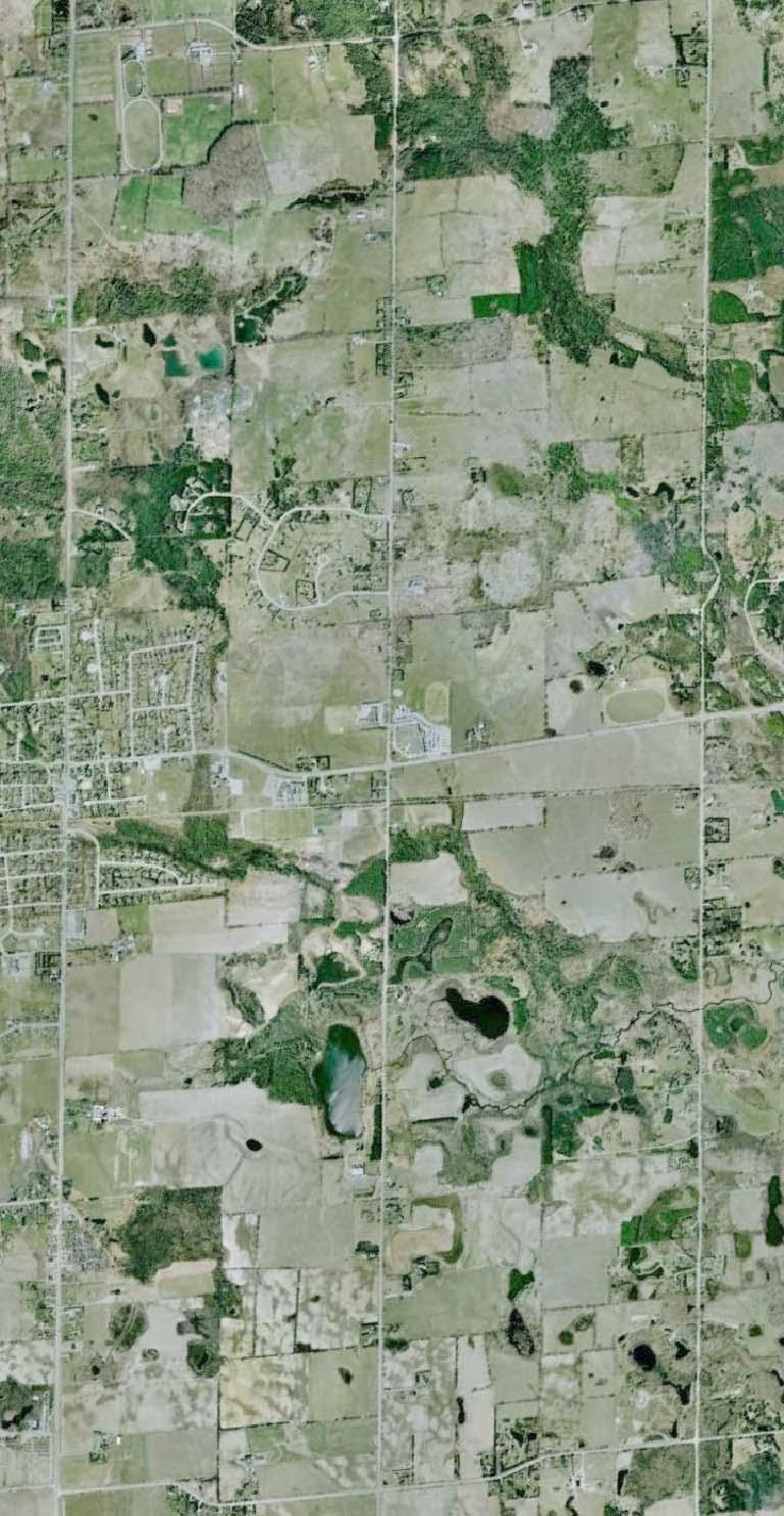
4 Caledon Villas Corporation Town of Caledon Caledon Villas Residential Subdivision Functional Servicing Report 1.0 Introduction Cole Engineering Group Ltd. (Cole Engineering) was retained by Caledon Villas Corporation (the Owner ) to prepare a Functional Servicing Report (FSR), for a proposed residential subdivision development in the Town of Caledon. The site is located north of Old Church Road and east of Innis Lake Road, as illustrated on Figure LOC-1 in Appendix A Background The site has an area of ha. The proposed development consists of 331 units, a 1.61 ha storm water management pond, a 3.34 ha Woodlot, and a 0.80 ha park. This report describes the proposed manner in which the Caledon Villas Residential Development will be serviced with watermain, sanitary and storm sewers. The existing topography and grading will also be addressed. 2.0 Reports This report is to be submitted and read in conjunction with: - A Soil Investigation for Proposed Residential Subdivision Northeast Corner of Old Church Road and Innis Lake Road, prepared by Soil Engineers Ltd on March Proposed Caledon East Subdivision Hydrogeologic Assessment, prepared by Geo Kamp Limited on June 27, Site Grading 3.1. Existing Topography The existing topography is shown on Figure STM-01 in Appendix A. The site generally slopes from north to south with the highest point located between proposed Lot 21 and 22 at the north property line. The most westerly part of the site slopes towards the existing school to the south with a gradient of 7.5% towards the existing swale along Innis Lake Road and is captured by an existing ditch inlet on the east side of Innis Lake Road adjacent to the existing school. The central and east part of the site slopes south towards Old Church Road at an average grade of 3.0% and drains towards the existing ditch along Old Church Road into two separate culverts. There are five existing buildings currently on the site and the lands are used for agricultural purposes. L Page 1
5 Caledon Villas Corporation Town of Caledon Caledon Villas Residential Subdivision Functional Servicing Report 3.2. Proposed Grades The internal roads will be designed to meet the Town of Caledon standards for minimum and maximum grades. The proposed road grades will range from approximately 0.75% to 5.00% with grades on majority of the streets between 0.75% and 3.00% and a slope of 3.00% or less at intersections. All roads will be designed to convey overland flow in accordance with the recommendations of the stormwater management plan in the report towards the stormwater management pond located at the south end of the site. The proposed lot grades along the west side of the site will match into the existing adjacent lots and the existing grades along Innis Lake Road. Street B along the north side of the existing school lands will require a 4:1 grading transition slope which will encroach into the school property to transition between the road grades and the existing grades along the school boundary. An agreement is being worked out between the developer and the school board to allow for this grading encroachment. The lots abutting the existing school lands will also match to existing and will be a combination of deck and walkout lots. The storm water management block at the southwest corner of the site will match with the existing school grades and the ditch line along Old Church Road with a 3:1 slope. Lots along Old Church Road will match into existing grades with a 3:1 slope. Proposed lots along the east side of the site will match into existing with a variety of lots types ranging from walkout lots to front draining lots. The proposed lots along the north side of the site will match to existing grades with a 4:1 slope south of the tree protection area for a vertical distance of 1.2m and in certain sections an additional 1.0m high retaining wall will be required at the toe of the 4:1 slope. These lots will be front draining lots towards the road. The grading of the residential lots will be designed as front, split, or rear walkout styles in order to minimize the cut/fill works. The need for retaining walls will be confirmed at the detail design stage. A preliminary design of the proposed road grades is illustrated on Figure GR-01 in Appendix A. 4.0 Erosion Sediment Control Prior to construction a mud mat will be installed at the construction entrance of the site. Silt fence will be installed along the perimeter of the downstream side of the site, to contain sediment within the site. Construction fence will be installed along the perimeter of the upstream side of the site to prevent unauthorized access, while allowing existing external flows into the site. Swales and rock check dams will be constructed within the site to convey flows to the temporary sediment pond. The temporary sediment pond will be constructed in the location of the permanent pond to collect sediment flows from the site and its external areas. 5.0 Water Supply 5.1. Existing Watermains A preliminary water servicing scheme for Caledon Villas Residential Subdivision is illustrated in Figure WM-01 in Appendix A. Two external watermains have been constructed to service the Caledon Villas lands. L Page 2
6 Caledon Villas Corporation Town of Caledon Caledon Villas Residential Subdivision Functional Servicing Report a) A 400 mm diameter watermain is located along Old Church Road; b) A 150 mm diameter watermain is located along Innis Lake Road The water supply system is currently being updated by the Region of Peel by twining the existing 300mm watermain on Old Church Road with a 400mm watermain. Prior to detail design hydrant flow tests will be performed to verify the system capacity for the additional demands related to this subdivision Internal Water Distribution The internal watermain network will connect to the existing 150 mm diameter watermain on Innis Lake Road, at the intersection of Street B and Innis Lake Road with a proposed 300 mm diameter watermain internal to the site by means of 300 mm x 150 mm reducer. A similar transition connection has been installed on Atchinson Drive on the east side of Innis Lake Road on the Chateaux of Caledon Subdivision. The proposed 300 mm diameter watermain will extend along Street B to Street A. The second water connection will be to the 400 mm diameter watermain on Old Church Road recently installed by the Region of Peel, at the intersection of Street A and Old Church Road, with a 300 mm diameter watermain. The 300 mm watermain on street A will connect to the proposed watermain on Street B forming the main trunk for the site. A 150 mm watermain network will be constructed on all local streets. Fire protection will be provided through hydrants spaced approximately 150 m interval for single detached, 70 m interval in townhouse areas as per Region of Peel standards. The layout of the proposed internal watermains is shown on Figure WM-01 in Appendix A. 6.0 Sanitary Drainage System 6.1. Existing Sanitary Drainage System The two existing sanitary sewers are located the intersection of Old Church Road and Innis Lake Road, and at the intersection of Innis Lake Road and Street B. The sanitary sewer at the intersection of Innis Lake Road and Street B is a 250 mm PVC sewer and connects to the sewer at the intersection of Old Church Road and Innis Lake Road. The sanitary sewer at the intersection of Old Church Road and Innis Lake Road is a 450 mm PVC sewer and connects to the Caledon Rail Trail sewer main Proposed Sanitary Connection The Caledon Villas lands will have 331 units with a total population of 1281 people. The sanitary sewer at the intersection of Innis Lake Road and Old Church Road will be extended 475 m to the east to the intersection of Old Church Road and Street A with a proposed 375mm sanitary sewer to service the Caledon Villas subdivision. The second sanitary connection at the intersection of Innis Lake Road and Street B will be a 250mm Sanitary Sewers. The internal sanitary flows will be collected by 250 mm diameter sanitary sewers to be constructed on the local roads to convey flows to the two outlet points of the Caledon Villas subdivision. L Page 3
7 Caledon Villas Corporation Town of Caledon Caledon Villas Residential Subdivision Functional Servicing Report 6.3. Proposed Sanitary Flows The sanitary sewers will be designed to current Region of Peel and Ministry of Environment (MOE) standards. The following criteria will apply. Residential Single Family (greater than 10m lots) 50 persons/ha Infiltration Rate m 3 /sec/m Peaking Factor Harmon Formula Minimum Pipe Size 250 mm Minimum Pipe Cover 2.7 m Minimum Velocity 0.75 m/s Maximum Velocity 3.0m/s The post development sanitary drainage plan is provided in Figure SAN-01 in Appendix A. 7.0 Storm Drainage System 7.1. Existing Storm Drainage System The existing topography of the site has a general slope towards the south and conveys stormwater by overland flow to the existing ditches along Innis Lake Road and Old Church Road. The storm flows in the ditches pass through existing culverts to the watercourse located on the south side of Old Church Road. The pre-development drainage area plan is provided in Figure STM-01 in Appendix A Existing Storm Flows The existing areas north of the proposed Caledon Villas subdivision drain towards two main catchments. A 3.73 ha area drains to the ditch along Innis Lake Road into an existing ditch inlet catchbasin adjacent to the school block. The flows captured by the existing ditch inlet catchbasin adjacent to the school block is conveyed by sewers through the school block to a 1400 mm diameter corrugated steel pipe outlet on the south side of Old Church Road. An area of ha (including the woodlot) flows south through the site towards the existing ditch along Old Church Road. A 1.10 ha area east of the Caledon Villas subdivision flows through the site into the ditch along Old Church Road. The flows in the ditch along Old Church Road pass under Old Church Road through an alternate 1200 mm culvert to the south side of Old Church Road. A 1200 mm diameter culvert south of the proposed Pond and a 1400 mm diameter culvert south of the School flow into separate existing swales leading to an existing watershed that outlet to the Centreville Creek Proposed Storm Drainage System The proposed minor storm drainage system will be designed to convey the 10-year storm event. Surface runoff along the proposed roads will be conveyed through roadside curb and gutters and captured by L Page 4
8 Caledon Villas Corporation Town of Caledon Caledon Villas Residential Subdivision Functional Servicing Report street catchbasins that will direct flows into the piped sewer system, as illustrated on STM-02 in Appendix A. The sewer system will outlet to a proposed 1.61 ha storm water management (SWM) pond located at the south west corner of the site, adjacent to the school block for quantity and quality control. The design of the major storm drainage system will be based on the Town of Caledon design standards and Ministry of Environment (MOE) guidelines. Rain events above the 10 year storm will be conveyed by overland flow within the right-of-way width along the proposed streets, and at designated 100 year capture points. The 100 year flows from the north external area of ha will be captured by rear lot catchbasins at structure 416, 426, and 435, respectively. The 100 year flows from the east external area will be captured by a rear lot catchbasins at structure 308. The major overland flow routes is along Street A. Majority of the overland flow from the local roads are conveyed to Street A and flow over the boulevard and into the north east corner of the pond as indicated on Figure STM-02 in Appendix A. Due to the existing grades along the north side of the school block, the 100 year flow will be captured into the storm sewers for the 1.11 ha area on Street B. The 100 year flows that are captured at Street B will be conveyed to the main storm sewer trunk on Street A. The main storm trunk sewer runs east along Street G and south along Street A and transitions from a 975mm diameter pipe to a 1800x900 box culvert Foundation Drain Collectors Foundation drain collectors (FDC) will be required due to insufficient cover of the storm sewer pipes in some areas as shown in Figure STM-03 in Appendix A. The FDC system will outlet at the existing 1200 mm diameter culvert along Old Church Road, at the same location as the SWM pond outlet. A 250 mm diameter pipe will run along the south limit of the SWM block to the intersection of Street A and Old Church Road. The 250 mm diameter FDC system will be installed north along Street A. 200 mm diameter connections will be installed at both the north and south intersections of Street C and Street D. The 200 mm diameter FDC system will service all the lots along Street D, and majority of the lots on Street C. The 250 mm diameter FDC along Street A will extend to Street B and run west until the end of Street B. This branch will service seven (7) lots along Street B. At the intersection of Street B and G, the FDC system will run north from the intersection and service an additional eight (8) lots on Street G Flood Plain Review The total drainage area, from the Caledon Villas subdivision and the contributing external areas, draining to the culverts along Old Church Road is ha. The floodplain is evaluated by SAAR Environmental Limited dated August, 2013, and was found not to be a significant source of habitat. In the existing condition the east culvert, along Old Church Road, drains into a low area in a farm without an overland flow outlet. The proposed condition will divert the existing flows into the stormwater management pond to the existing west culvert that outlets into a nearby creek, south of the site. The proposed condition will prevent surface ponding in the farm, and allow for on site quantity and quality controls. L Page 5
9 Caledon Villas Corporation Town of Caledon Caledon Villas Residential Subdivision Functional Servicing Report 8.0 Stormwater Management 8.1. Design Criteria The proposed development should meet the Ministry of Environment standards as set out in the MOE 2003 Stormwater Management Planning & Design (SWMPD) manual. - Post-development peak flows for all storm events up to the 100-year frequency design storm should be controlled to the unit flows resulting from the Humber River Watershed unit rate equation, as provided by the TRCA; - Stormwater should be treated to Enhanced (Level 1) protection as defined in the SWMPD Manual; - Erosion potential is to be mitigated through maximizing infiltration through the site. In addition, runoff from the 25 mm event will be detained over at least 48 hours; and, - Existing water balance conditions are to be maintained, as requested by the TRCA. Design storm information from the Town and the latest AES rainfall data from the TRCA are to be used for analysis Existing Hydrological Conditions Pre-development drainage areas for the site are shown in STM-01 in Appendix A. Site drainage is predominately from north to south, with most of the external existing area (56.68 ha) flowing through the Caledon Villas subdivision to the ditch along Old Church Road. The flows from a smaller external area (3.73 ha) from the north is collected along the ditch on Innis Lake Road, and is captured by a ditch inlet catchbasin on the east side of Innis Lake Road. The flow from the ditch inlet catchbasin is conveyed through the school block via storm sewer and outlets at a culvert on the south side of Old Church Road into an existing swale leading to the Centreville Creek. The flow targets for will be established by Humber River Watershed unit flow rate equations, as provided by the TRCA, were used in order to determine the target pre-development flows. The target pre-development flows are summarized in Table 1. Storm Event Table 1: Humber River Watershed Unit Rate Flows Uncontrolled External Flows including Wood Lot ha (m 3 /s) Unit Flow Rates Development Area ha to Pond (m 3 /s) Total Target Flow 2 Year Year Year Year Year Year L Page 6
10 Caledon Villas Corporation Town of Caledon Caledon Villas Residential Subdivision Functional Servicing Report 8.3. Proposed Drainage System External Drainage The proposed development condition will increase the percentage of the site in impervious cover to approximately 57%, this figure is conservative and will likely revised downward at with the detailed design of the subdivision. To mitigate these hydrologic changes, it is proposed to maximize storm drainage from the development to a SWM Pond, prior to the discharge to an existing 1400 mm culvert crossing to the south side of Old Church Road. The existing culvert discharges to an existing swale that flows into the Centreville Creek. The external drainage area A1 (55.68 ha) is an undeveloped area that will be captured at two ditch inlet catchbasins, structure 416 and 426, located at opposite sides of the park along the northern property line and a ditch inlet catchbasin, structure 435 located close to the west side of the site. The external drainage area A3 located east of the Caledon Villas subdivision will drain to a ditch inlet catchbasin, structure 308, located at the south east corner of the site. All flows captured into the storm sewer system drains into the SWM pond at the Street A pond inlet Site Drainage Impervious calculations were undertaken for the post-development drainage areas based on the maximum allowable building envelopes under the proposed zoning. The relevant drainage parameters of the post-development drainage areas contributing to the outflow are provided in Tables 2 and 3. The post-development NASHYD input parameters for the V02 model are provided in Appendix B and the STANDHYD input parameters are provided in Appendix C. The output from the V02 model for postdevelopment conditions is provided in Appendix D. Table 2 Post-development Input Parameters (NASHHYD Commands) Catchment Drainage Area (ha) CN TP (hr) A1POST A3POST Table 3 Post-development Input Parameters (STANHYD Commands) Catchment Drainage Area (ha) XIMP TIMP A2POST Peak Flow / Quantity Controls A stage-storage-discharge relationship was developed for the proposed SWM pond for which the detailed flow summary is provided in Appendix E. The stage-storage-discharge calculations are provided in Appendix F. The results from the V02 model and analysis are provided in Table 4 and 5 for the AES storm events over 6-hour and 12-hour durations. L Page 7
11 Caledon Villas Corporation Town of Caledon Caledon Villas Residential Subdivision Functional Servicing Report Table 4 Post-Development Quantity Control Analysis (6-hour AES) Target at Inflow to Peak Flow SWM Pond SWM at Pond Pond Outfall Pond Outfall Elevation (m 3 /s) (m 3 /s) (m 3 /s) (m) Event SWM Pond Storage (m 3 ) 2-Year ,012 5-Year , Year , Year , Year , Year ,140 Table 5 Post-Development Quantity Control Analysis (12-hour AES) Target at Inflow to Peak Flow SWM Pond SWM at Pond Pond Outfall Pond Outfall Elevation (m 3 /s) (m 3 /s) (m 3 /s) (m) Event SWM Pond Storage(m 3 ) 2-Year ,715 5-Year , Year , Year , Year , Year ,311 The proposed SWM pond provides 27,609 m 3 at an elevation of m. Table 4 and 5 illustrates the required stage storage to control the post-development peak flows to pre-development conditions is 24,311 m 3 at an elevation of m. Therefore, the proposed SWM control measures are capable of mitigating post-development flow increases Water Quality Control Stormwater treatment must be Enhanced (Level 1) Protection criteria as defined by the SWMPD Manual. All minor system drainage from the development site will be treated in the proposed wet pond facility. The required permanent pool storage to meet the quality control criteria is provided in Table 6. Detailed calculations are provided in Appendix G. Table 6 Water Quality Requirements Total Developed Area Required Permanent Minimum Extended % Impervious to SWM Pond (ha) Pool Volume (m 3 ) Detention Volume (m 3 ) % The proposed pond provides 5197 m 3 of permanent pool volume between the bottom of the pond at elevation m and the permanent pool elevation m, and therefore meets the water quality requirements. To avoid interaction with the water table, the pond permanent pool will be lined by an impermeable geosynthetic membrane as recommended by the soils consultant. L Page 8
12 Caledon Villas Corporation Town of Caledon Caledon Villas Residential Subdivision Functional Servicing Report A 90 mm orifice plate will be used to provide 3,553 m 3 of storage for the 25 mm 4 hr Chicago Storm at elevation with a peak release rate of m 3 /s and total extended detention time of hr to minimize erosion downstream of the pond outfall. The proposed SWM pond has a sediment forebay approximately 38 m in length and m in width. Forebay sizing calculations, provided in Appendix H, were undertaken to confirm the provided forebay dimensions summarized in Table 7. Table 7 Forebay Sizing Requirements Parameter Required Size (m) Provided Size (m) Minimum Forebay Length for Settling (V S = m/s) Minimum Dispersion Length Minimum Bottom Width The proposed sediment forebay meets all minimum requirements and is expected to perform well given its large size in relation to the required values Water Balance The Hydrogeologic Assessment by Geo Kamp Limited states that the predevelopment average annual site infiltration is approximately 62,395 m 3, form an annual recharge rate of 241 mm/year over the ha. Assuming a post development condition in which 55% of the site surface becomes impervious in the form of roofs, roads and driveways, would cause a net reduction in infiltration of 34,317 m 3. It is estimated that an infiltration basin with a bottom area of 284 m 2 would infiltrate 94 m 3 per day or 34,317 m 3 per year. This can be accomplished by the following measures or any combination thereof: 331 sockway pits (one per lot) would provide 331 m 2 bottom area of combined infiltration basin for site exceeding the 284 m 2 requirement. 284 m of infiltration trenches along rear yard swales 1 m deep by 1 m wide would provide 284 m 2 of combined infiltration basin required for water balance of the project. 9.0 Conclusions The proposed Caledon Villas residential development can readily be serviced with storm, sanitary, and watermain utilizing existing and proposed infrastructure. Water supply will be provided by connecting to the existing 150 mm watermain at the intersection of Innis Lake Road and Street B and the 400 mm watermain on the north shoulder of Old Church Road. The proposed watermain trunk will be 300 mm diameter and extend from Street A to Street B. The local 150 mm watermains will branch off of the 300 mm watermain to service the internal lots. The proposed sanitary sewer will convey flows to the existing Innis Lake Road sanitary sewers. The two separate connection points are located at the intersection of Innis Lake Road and Street B, and Innis Lake Road and Old Church Road. The sanitary sewer on Innis Lake Road has sufficient size and depth to service the Caledon Villas residential subdivision. L Page 9
13
14 APPENDIX A Figures
15
16
17
18
19
20
21
22 APPENDIX B NASHHYD Input Parameters
23 Sheet14 Post-Development NASHYD Input Parameters Caledon Villas Corporation File No. L Date: August, 2013 Parameter Unit Description A1POST A3POST Area ha Watershed Area TP hr Unit Hydrograph Time to Peak DT min Time Step Increment 10 DWF cms Dry Weather Flow (Base Flow) 0 CN - SCS Curve Number 78 IA mm Initial Abstraction 10 N - Number of Linear Reservior 1 Rain mm/hr Optional Rainfall Intensities 0-Without Rainfall Area Number Time of Concentration Calculation Area Cpost L Elevation Change Sw Tp (Airport) (ha) (m) (m) (m/m) (hr) A1POST A3POST Page 1
24 APPENDIX C STANDHYD Input Parameters
25 Sheet13 Post-Development STANDHYD Input Parameters Caledon Villas Corporation File No. L Date: August, 2013 SIDEWALK Area Number Total Area Length of Sidewalk Width of Indirect Impervious Sidewalk Area (ha) (m) (m) (ha) A3POST ROAD Area Number Total Area Length of Road Width of Road Direct Impervious Area (ha) (m) (m) (ha) A3POST LOTS Area Number Dwelling - Detached Total Area per Lot 500 m 2 Rooftop Area per Lot 252 m 2 Driveway Area 54 m 2 Total Area # of Detached Dwelling Lots # of Semi- Detached Dwelling Lots Total Lot Area Total Rooftop Area Driveway Area Area of Row Dwellings/ Commercial Impervious Area - Row Dwellings/ Commercial Total Indirect Impervious Area (ha) (ha) (ha) (ha) (ha) (ha) (ha) A3POST TOTAL IMPERVIOUS AREA Area Number Total Area Direct Impervious Area Indirect Impervious Area Total Impervious Area (ha) (ha) (ha) (ha) (%) (%) A1POST XIMP TIMP Page 1
26 APPENDIX D V02 Model - Post Development Conditions
27 =========================================================================================================== V V I SSSSS U U A L V V I SS U U A A L V V I SS U U AAAAA L V V I SS U U A A L VV I SSSSS UUUUU A A LLLLL OOO TTTTT TTTTT H H Y Y M M OOO TM O O T T H H Y Y MM MM O O O O T T H H Y M M O O Company OOO T T H H Y M M OOO Serial Developed and Distributed by Clarifica Inc. Copyright 1996, 2007 Clarifica Inc. All rights reserved. ***** D E T A I L E D O U T P U T ***** Input filename: C:\Program Files (x86)\visual Otthymo 2.4\VO2\voin.dat Output filename: C:\WinTemp\2bd20bf d4-b3ef-1c44c26c346e\Scenario.out Summary filename: C:\WinTemp\2bd20bf d4-b3ef-1c44c26c346e\Scenario.sum DATE: 04/04/2014 TIME: 06:00:11 USER: COMMENTS: **************************** ** SIMULATION NUMBER: 1 ** **************************** READ STORM Filename: C:\WinTemp\2bd 20bf d4-b3ef-1c44c26c346e\ 5966ba94-7d1c-4290-b9ed-ae4f2eceb5d7 Ptotal= mm Comments: 2yr/6hr TIME RAIN TIME RAIN ' TIME RAIN TIME RAIN hrs mm/hr hrs mm/hr ' hrs mm/hr hrs mm/hr NASHYD (0004) Area (ha)= 1.10 Curve Number (CN)= 78.0 U.H. Tp(hrs)= 0.39 NOTE: RAINFALL WAS TRANSFORMED TO 5.0 MIN. TIME STEP TRANSFORMED HYETOGRAPH ---- TIME RAIN TIME RAIN ' TIME RAIN TIME RAIN hrs mm/hr hrs mm/hr ' hrs mm/hr hrs mm/hr
28 Unit Hyd Qpeak (cms)= PEAK FLOW (cms)= (i) TIME TO PEAK (hrs)= RUNOFF VOLUME (mm)= TOTAL RAINFALL (mm)= RUNOFF COEFFICIENT = NASHYD (0001) Area (ha)= Curve Number (CN)= 78.0 U.H. Tp(hrs)= 0.74 Unit Hyd Qpeak (cms)= PEAK FLOW (cms)= (i) TIME TO PEAK (hrs)= RUNOFF VOLUME (mm)= TOTAL RAINFALL (mm)= RUNOFF COEFFICIENT = ADD HYD (0012) = 3 AREA QPEAK TPEAK R.V. (ha) (cms) (hrs) (mm) ID1= 1 (0001): ID2= 2 (0004): ================================================== ID = 3 (0012): NOTE: PEAK FLOWS DO NOT INCLUDE BASEFLOWS IF ANY STANDHYD (0003) Area (ha)= ID= 1 DT= 5.0 min Total Imp(%)= Dir. Conn.(%)= IMPERVIOUS PERVIOUS (i) Surface Area (ha)= Dep. Storage (mm)= Average Slope (%)= Length (m)= Mannings n = Max.Eff.Inten.(mm/hr)= over (min) Storage Coeff. (min)= 8.15 (ii) (ii) Unit Hyd. Tpeak (min)= Unit Hyd. peak (cms)= *TOTALS* PEAK FLOW (cms)= (iii) TIME TO PEAK (hrs)= RUNOFF VOLUME (mm)= TOTAL RAINFALL (mm)= RUNOFF COEFFICIENT = ***** WARNING:FOR AREAS WITH IMPERVIOUS RATIOS BELOW 20% YOU SHOULD CONSIDER SPLITTING THE AREA. (i) CN PROCEDURE SELECTED FOR PERVIOUS LOSSES: CN* = 78.0 Ia = Dep. Storage (Above) (ii) TIME STEP (DT) SHOULD BE SMALLER OR EQUAL THAN THE STORAGE COEFFICIENT. (iii) PEAK FLOW DOES NOT INCLUDE BASEFLOW IF ANY
29 ADD HYD (0027) = 3 AREA QPEAK TPEAK R.V. (ha) (cms) (hrs) (mm) ID1= 1 (0003): ID2= 2 (0012): ================================================== ID = 3 (0027): NOTE: PEAK FLOWS DO NOT INCLUDE BASEFLOWS IF ANY RESERVOIR (0021) IN= 2---> OUT= 1 DT= 5.0 min OUTFLOW STORAGE OUTFLOW STORAGE (cms) (ha.m.) (cms) (ha.m.) AREA QPEAK TPEAK R.V. (ha) (cms) (hrs) (mm) INFLOW : ID= 2 (0027) OUTFLOW: ID= 1 (0021) PEAK FLOW REDUCTION [Qout/Qin](%)= 1.56 TIME SHIFT OF PEAK FLOW (min)= MAXIMUM STORAGE USED (ha.m.)= NASHYD (0035) Area (ha)= Curve Number (CN)= 78.0 U.H. Tp(hrs)= 0.74 Unit Hyd Qpeak (cms)= PEAK FLOW (cms)= (i) TIME TO PEAK (hrs)= RUNOFF VOLUME (mm)= TOTAL RAINFALL (mm)= RUNOFF COEFFICIENT = **************************** ** SIMULATION NUMBER: 2 ** **************************** READ STORM Filename: C:\WinTemp\2bd 20bf d4-b3ef-1c44c26c346e\ d5b c-411c-b49d-1eb44c0da7bb Ptotal= mm Comments: 5yr/6hr TIME RAIN TIME RAIN ' TIME RAIN TIME RAIN hrs mm/hr hrs mm/hr ' hrs mm/hr hrs mm/hr NASHYD (0004) Area (ha)= 1.10 Curve Number (CN)= 78.0 U.H. Tp(hrs)= 0.39 NOTE: RAINFALL WAS TRANSFORMED TO 5.0 MIN. TIME STEP.
30 ---- TRANSFORMED HYETOGRAPH ---- TIME RAIN TIME RAIN ' TIME RAIN TIME RAIN hrs mm/hr hrs mm/hr ' hrs mm/hr hrs mm/hr Unit Hyd Qpeak (cms)= PEAK FLOW (cms)= (i) TIME TO PEAK (hrs)= RUNOFF VOLUME (mm)= TOTAL RAINFALL (mm)= RUNOFF COEFFICIENT = NASHYD (0001) Area (ha)= Curve Number (CN)= 78.0 U.H. Tp(hrs)= 0.74 Unit Hyd Qpeak (cms)= PEAK FLOW (cms)= (i) TIME TO PEAK (hrs)= RUNOFF VOLUME (mm)= TOTAL RAINFALL (mm)= RUNOFF COEFFICIENT = ADD HYD (0012) = 3 AREA QPEAK TPEAK R.V. (ha) (cms) (hrs) (mm) ID1= 1 (0001): ID2= 2 (0004): ================================================== ID = 3 (0012): NOTE: PEAK FLOWS DO NOT INCLUDE BASEFLOWS IF ANY STANDHYD (0003) Area (ha)= ID= 1 DT= 5.0 min Total Imp(%)= Dir. Conn.(%)= IMPERVIOUS PERVIOUS (i) Surface Area (ha)= Dep. Storage (mm)= Average Slope (%)= Length (m)= Mannings n = Max.Eff.Inten.(mm/hr)= over (min) Storage Coeff. (min)= 7.27 (ii) (ii) Unit Hyd. Tpeak (min)= Unit Hyd. peak (cms)= *TOTALS* PEAK FLOW (cms)= (iii) TIME TO PEAK (hrs)=
31 RUNOFF VOLUME (mm)= TOTAL RAINFALL (mm)= RUNOFF COEFFICIENT = ***** WARNING:FOR AREAS WITH IMPERVIOUS RATIOS BELOW 20% YOU SHOULD CONSIDER SPLITTING THE AREA. (i) CN PROCEDURE SELECTED FOR PERVIOUS LOSSES: CN* = 78.0 Ia = Dep. Storage (Above) (ii) TIME STEP (DT) SHOULD BE SMALLER OR EQUAL THAN THE STORAGE COEFFICIENT. (iii) PEAK FLOW DOES NOT INCLUDE BASEFLOW IF ANY ADD HYD (0027) = 3 AREA QPEAK TPEAK R.V. (ha) (cms) (hrs) (mm) ID1= 1 (0003): ID2= 2 (0012): ================================================== ID = 3 (0027): NOTE: PEAK FLOWS DO NOT INCLUDE BASEFLOWS IF ANY RESERVOIR (0021) IN= 2---> OUT= 1 DT= 5.0 min OUTFLOW STORAGE OUTFLOW STORAGE (cms) (ha.m.) (cms) (ha.m.) AREA QPEAK TPEAK R.V. (ha) (cms) (hrs) (mm) INFLOW : ID= 2 (0027) OUTFLOW: ID= 1 (0021) PEAK FLOW REDUCTION [Qout/Qin](%)= 1.14 TIME SHIFT OF PEAK FLOW (min)= MAXIMUM STORAGE USED (ha.m.)= NASHYD (0035) Area (ha)= Curve Number (CN)= 78.0 U.H. Tp(hrs)= 0.74 Unit Hyd Qpeak (cms)= PEAK FLOW (cms)= (i) TIME TO PEAK (hrs)= RUNOFF VOLUME (mm)= TOTAL RAINFALL (mm)= RUNOFF COEFFICIENT = **************************** ** SIMULATION NUMBER: 3 ** **************************** READ STORM Filename: C:\WinTemp\2bd 20bf d4-b3ef-1c44c26c346e\ 6d8ccf00-72bf-495f f14f6846a62 Ptotal= mm Comments: 10yr/6hr TIME RAIN TIME RAIN ' TIME RAIN TIME RAIN hrs mm/hr hrs mm/hr ' hrs mm/hr hrs mm/hr
32 NASHYD (0004) Area (ha)= 1.10 Curve Number (CN)= 78.0 U.H. Tp(hrs)= 0.39 NOTE: RAINFALL WAS TRANSFORMED TO 5.0 MIN. TIME STEP TRANSFORMED HYETOGRAPH ---- TIME RAIN TIME RAIN ' TIME RAIN TIME RAIN hrs mm/hr hrs mm/hr ' hrs mm/hr hrs mm/hr Unit Hyd Qpeak (cms)= PEAK FLOW (cms)= (i) TIME TO PEAK (hrs)= RUNOFF VOLUME (mm)= TOTAL RAINFALL (mm)= RUNOFF COEFFICIENT = NASHYD (0001) Area (ha)= Curve Number (CN)= 78.0 U.H. Tp(hrs)= 0.74 Unit Hyd Qpeak (cms)= PEAK FLOW (cms)= (i) TIME TO PEAK (hrs)= RUNOFF VOLUME (mm)= TOTAL RAINFALL (mm)= RUNOFF COEFFICIENT = ADD HYD (0012) = 3 AREA QPEAK TPEAK R.V. (ha) (cms) (hrs) (mm) ID1= 1 (0001): ID2= 2 (0004): ================================================== ID = 3 (0012): NOTE: PEAK FLOWS DO NOT INCLUDE BASEFLOWS IF ANY STANDHYD (0003) Area (ha)= ID= 1 DT= 5.0 min Total Imp(%)= Dir. Conn.(%)= 12.00
33 IMPERVIOUS PERVIOUS (i) Surface Area (ha)= Dep. Storage (mm)= Average Slope (%)= Length (m)= Mannings n = Max.Eff.Inten.(mm/hr)= over (min) Storage Coeff. (min)= 6.84 (ii) (ii) Unit Hyd. Tpeak (min)= Unit Hyd. peak (cms)= *TOTALS* PEAK FLOW (cms)= (iii) TIME TO PEAK (hrs)= RUNOFF VOLUME (mm)= TOTAL RAINFALL (mm)= RUNOFF COEFFICIENT = ***** WARNING:FOR AREAS WITH IMPERVIOUS RATIOS BELOW 20% YOU SHOULD CONSIDER SPLITTING THE AREA. (i) CN PROCEDURE SELECTED FOR PERVIOUS LOSSES: CN* = 78.0 Ia = Dep. Storage (Above) (ii) TIME STEP (DT) SHOULD BE SMALLER OR EQUAL THAN THE STORAGE COEFFICIENT. (iii) PEAK FLOW DOES NOT INCLUDE BASEFLOW IF ANY ADD HYD (0027) = 3 AREA QPEAK TPEAK R.V. (ha) (cms) (hrs) (mm) ID1= 1 (0003): ID2= 2 (0012): ================================================== ID = 3 (0027): NOTE: PEAK FLOWS DO NOT INCLUDE BASEFLOWS IF ANY RESERVOIR (0021) IN= 2---> OUT= 1 DT= 5.0 min OUTFLOW STORAGE OUTFLOW STORAGE (cms) (ha.m.) (cms) (ha.m.) AREA QPEAK TPEAK R.V. (ha) (cms) (hrs) (mm) INFLOW : ID= 2 (0027) OUTFLOW: ID= 1 (0021) PEAK FLOW REDUCTION [Qout/Qin](%)= 1.00 TIME SHIFT OF PEAK FLOW (min)= MAXIMUM STORAGE USED (ha.m.)= NASHYD (0035) Area (ha)= Curve Number (CN)= 78.0 U.H. Tp(hrs)= 0.74 Unit Hyd Qpeak (cms)= PEAK FLOW (cms)= (i) TIME TO PEAK (hrs)= RUNOFF VOLUME (mm)= TOTAL RAINFALL (mm)= RUNOFF COEFFICIENT =
34 **************************** ** SIMULATION NUMBER: 4 ** **************************** READ STORM Filename: C:\WinTemp\2bd 20bf d4-b3ef-1c44c26c346e\ 2220c626-bb78-48cb-98d1-0a4b1124f8f2 Ptotal= mm Comments: 25yr/6hr TIME RAIN TIME RAIN ' TIME RAIN TIME RAIN hrs mm/hr hrs mm/hr ' hrs mm/hr hrs mm/hr NASHYD (0004) Area (ha)= 1.10 Curve Number (CN)= 78.0 U.H. Tp(hrs)= 0.39 NOTE: RAINFALL WAS TRANSFORMED TO 5.0 MIN. TIME STEP TRANSFORMED HYETOGRAPH ---- TIME RAIN TIME RAIN ' TIME RAIN TIME RAIN hrs mm/hr hrs mm/hr ' hrs mm/hr hrs mm/hr Unit Hyd Qpeak (cms)= PEAK FLOW (cms)= (i) TIME TO PEAK (hrs)= RUNOFF VOLUME (mm)= TOTAL RAINFALL (mm)= RUNOFF COEFFICIENT = NASHYD (0001) Area (ha)= Curve Number (CN)= 78.0 U.H. Tp(hrs)= 0.74 Unit Hyd Qpeak (cms)= PEAK FLOW (cms)= (i) TIME TO PEAK (hrs)= RUNOFF VOLUME (mm)= TOTAL RAINFALL (mm)= RUNOFF COEFFICIENT =
35 ADD HYD (0012) = 3 AREA QPEAK TPEAK R.V. (ha) (cms) (hrs) (mm) ID1= 1 (0001): ID2= 2 (0004): ================================================== ID = 3 (0012): NOTE: PEAK FLOWS DO NOT INCLUDE BASEFLOWS IF ANY STANDHYD (0003) Area (ha)= ID= 1 DT= 5.0 min Total Imp(%)= Dir. Conn.(%)= IMPERVIOUS PERVIOUS (i) Surface Area (ha)= Dep. Storage (mm)= Average Slope (%)= Length (m)= Mannings n = Max.Eff.Inten.(mm/hr)= over (min) Storage Coeff. (min)= 6.41 (ii) (ii) Unit Hyd. Tpeak (min)= Unit Hyd. peak (cms)= *TOTALS* PEAK FLOW (cms)= (iii) TIME TO PEAK (hrs)= RUNOFF VOLUME (mm)= TOTAL RAINFALL (mm)= RUNOFF COEFFICIENT = ***** WARNING:FOR AREAS WITH IMPERVIOUS RATIOS BELOW 20% YOU SHOULD CONSIDER SPLITTING THE AREA. (i) CN PROCEDURE SELECTED FOR PERVIOUS LOSSES: CN* = 78.0 Ia = Dep. Storage (Above) (ii) TIME STEP (DT) SHOULD BE SMALLER OR EQUAL THAN THE STORAGE COEFFICIENT. (iii) PEAK FLOW DOES NOT INCLUDE BASEFLOW IF ANY ADD HYD (0027) = 3 AREA QPEAK TPEAK R.V. (ha) (cms) (hrs) (mm) ID1= 1 (0003): ID2= 2 (0012): ================================================== ID = 3 (0027): NOTE: PEAK FLOWS DO NOT INCLUDE BASEFLOWS IF ANY RESERVOIR (0021) IN= 2---> OUT= 1 DT= 5.0 min OUTFLOW STORAGE OUTFLOW STORAGE (cms) (ha.m.) (cms) (ha.m.) AREA QPEAK TPEAK R.V. (ha) (cms) (hrs) (mm) INFLOW : ID= 2 (0027) OUTFLOW: ID= 1 (0021) PEAK FLOW REDUCTION [Qout/Qin](%)= TIME SHIFT OF PEAK FLOW (min)= MAXIMUM STORAGE USED (ha.m.)=
36 NASHYD (0035) Area (ha)= Curve Number (CN)= 78.0 U.H. Tp(hrs)= 0.74 Unit Hyd Qpeak (cms)= PEAK FLOW (cms)= (i) TIME TO PEAK (hrs)= RUNOFF VOLUME (mm)= TOTAL RAINFALL (mm)= RUNOFF COEFFICIENT = **************************** ** SIMULATION NUMBER: 5 ** **************************** READ STORM Filename: C:\WinTemp\2bd 20bf d4-b3ef-1c44c26c346e\ 2b0544d7-ced ad-ece27981cbf8 Ptotal= mm Comments: 50yr/6hr TIME RAIN TIME RAIN ' TIME RAIN TIME RAIN hrs mm/hr hrs mm/hr ' hrs mm/hr hrs mm/hr NASHYD (0004) Area (ha)= 1.10 Curve Number (CN)= 78.0 U.H. Tp(hrs)= 0.39 NOTE: RAINFALL WAS TRANSFORMED TO 5.0 MIN. TIME STEP TRANSFORMED HYETOGRAPH ---- TIME RAIN TIME RAIN ' TIME RAIN TIME RAIN hrs mm/hr hrs mm/hr ' hrs mm/hr hrs mm/hr Unit Hyd Qpeak (cms)= PEAK FLOW (cms)= (i) TIME TO PEAK (hrs)= RUNOFF VOLUME (mm)= TOTAL RAINFALL (mm)= RUNOFF COEFFICIENT =
37 NASHYD (0001) Area (ha)= Curve Number (CN)= 78.0 U.H. Tp(hrs)= 0.74 Unit Hyd Qpeak (cms)= PEAK FLOW (cms)= (i) TIME TO PEAK (hrs)= RUNOFF VOLUME (mm)= TOTAL RAINFALL (mm)= RUNOFF COEFFICIENT = ADD HYD (0012) = 3 AREA QPEAK TPEAK R.V. (ha) (cms) (hrs) (mm) ID1= 1 (0001): ID2= 2 (0004): ================================================== ID = 3 (0012): NOTE: PEAK FLOWS DO NOT INCLUDE BASEFLOWS IF ANY STANDHYD (0003) Area (ha)= ID= 1 DT= 5.0 min Total Imp(%)= Dir. Conn.(%)= IMPERVIOUS PERVIOUS (i) Surface Area (ha)= Dep. Storage (mm)= Average Slope (%)= Length (m)= Mannings n = Max.Eff.Inten.(mm/hr)= over (min) Storage Coeff. (min)= 6.14 (ii) (ii) Unit Hyd. Tpeak (min)= Unit Hyd. peak (cms)= *TOTALS* PEAK FLOW (cms)= (iii) TIME TO PEAK (hrs)= RUNOFF VOLUME (mm)= TOTAL RAINFALL (mm)= RUNOFF COEFFICIENT = ***** WARNING:FOR AREAS WITH IMPERVIOUS RATIOS BELOW 20% YOU SHOULD CONSIDER SPLITTING THE AREA. (i) CN PROCEDURE SELECTED FOR PERVIOUS LOSSES: CN* = 78.0 Ia = Dep. Storage (Above) (ii) TIME STEP (DT) SHOULD BE SMALLER OR EQUAL THAN THE STORAGE COEFFICIENT. (iii) PEAK FLOW DOES NOT INCLUDE BASEFLOW IF ANY ADD HYD (0027) = 3 AREA QPEAK TPEAK R.V. (ha) (cms) (hrs) (mm) ID1= 1 (0003): ID2= 2 (0012): ================================================== ID = 3 (0027): NOTE: PEAK FLOWS DO NOT INCLUDE BASEFLOWS IF ANY RESERVOIR (0021) IN= 2---> OUT= 1 DT= 5.0 min OUTFLOW STORAGE OUTFLOW STORAGE (cms) (ha.m.) (cms) (ha.m.)
STREUVER FIDELCO CAPPELLI, LLC YONKERS DOWNTOWN DEVELOPMENT PHASE 1. DRAFT ENVIRONMENTAL IMPACT STATEMENT For: PALISADES POINT
 STREUVER FIDELCO CAPPELLI, LLC YONKERS DOWNTOWN DEVELOPMENT PHASE 1 DRAFT ENVIRONMENTAL IMPACT STATEMENT For: PALISADES POINT Prepared by: PAULUS, SOKOLOWSKI & SARTOR STORMWATER MANAGEMENT 1. Methodology
Stormwater Management Report
 1150 Morrison Drive, Suite 410 Ottawa, ON, K2H 8S9 T.613.828.7800 F.613.828.2600 Project No. 2151738A Stormwater Management Report Hydro Ottawa Hunt Club Drive, Gloucester, Ontario Prepared for November
Table 1 - Infiltration Rates
 Stantec Consulting Ltd. 100-300 Hagey Boulevard, Waterloo ON N2L 0A4 November 14, 2017 File: 161413228/10 Attention: Mr. Michael Witmer, BES, MPA, MCIP, RPP City of Guelph 1 Carden Street Guelph ON N1H
HOTEL KANATA 160 HEARST WAY KANATA, ONTARIO SERVICING REPORT. Prepared for: David Johnston Architect. Prepared By:
 HOTEL KANATA 160 HEARST WAY KANATA, ONTARIO SERVICING REPORT Prepared for: David Johnston Architect Prepared By: BaseTech Consulting Inc. 309 Roywood Crescent Newmarket, Ontario L3Y 1A6 BCI Project No.
D.M. Wills Associates Limited PARTNERS IN ENGINEERING. Stormwater Management Report. City of Peterborough
 Stormwater Management Report City of Peterborough P-20-12 Parkway Corridor Class Environmental Assessment Jackson Park Parkhill Road West to Chemong Road D.M. Wills Project No. 12-5061 D.M. Wills Associates
SERVICING BRIEF & STORMWATER MANAGEMENT REPORT Colonial Road Sarsfield (Ottawa), Ontario. Report No June 15, 2017
, Ontario. Report No June 15, 2017") SERVICING BRIEF & STORMWATER MANAGEMENT REPORT 2980 Colonial Road Sarsfield (Ottawa), Ontario Report No. 16033 June 15, 2017 D. B. G R A Y E N G I N E E R I N G I N C. Stormwater Management - Grading &
SERVICING BRIEF & STORMWATER MANAGEMENT REPORT 2980 Colonial Road Sarsfield (Ottawa), Ontario Report No. 16033 June 15, 2017 D. B. G R A Y E N G I N E E R I N G I N C. Stormwater Management - Grading &
Stormwater Guidelines and Case Studies. CAHILL ASSOCIATES Environmental Consultants West Chester, PA (610)
") Stormwater Guidelines and Case Studies CAHILL ASSOCIATES Environmental Consultants West Chester, PA (610) 696-4150 www.thcahill.com Goals and Challenges for Manual State Stormwater Policy More Widespread
Stormwater Guidelines and Case Studies CAHILL ASSOCIATES Environmental Consultants West Chester, PA (610) 696-4150 www.thcahill.com Goals and Challenges for Manual State Stormwater Policy More Widespread
FUNCTIONAL SERVICING REPORT AND SWM REPORT
 FUNCTIONAL SERVICING REPORT AND SWM REPORT 104 WHITE CRESCENT CITY OF BARRIE, COUNTY OF SIMCOE December 2018 18058 TABLE OF CONTENTS 1. INTRODUCTION... 4 2. SUPPORTING DOCUMENTS... 4 3. DESIGN POPULATION...
Project Description. Project Options. End Analysis On... Apr 26, :00:00. Rainfall Details
 Project Description File Name... 323 - Att Pond 3 East PIPES ONLY.SPF Project Options Flow Units... Elevation Type... Hydrology Method... EPA SWMM Infiltration Method... Link Routing Method... Enable Overflow
STORMWATER REPORT FRITO LAY SUBDIVISION NO. 3
 STORMWATER REPORT FRITO LAY SUBDIVISION NO. 3 May 2018 STORMWATER REPORT I. Subdivision Data a. The parcel is adjacent to the existing Frito Lay property in Topeka; and the subject plat application encompasses
D. B. G R A Y E N G I N E E R I N G I N C.
 STORMWATER MANAGEMENT REPORT 948 Hunt lub Road Ottawa, Ontario Report No. 12020-SWM August 27, 2012 Revised April 21, 2014 Revised December 9, 2014 Revised April 14, 2015 D. B. G R A Y E N G I N E E R
STORMWATER MANAGEMENT ASSESSMENT TECHNICAL MEMORANDUM DRAFT FINAL FOSTER DRIVE AREA SANITARY SERVICING AND STORMWATER MANAGEMENT CLASS EA
 The City of Committed to Total Service Excellence STORMWATER MANAGEMENT ASSESSMENT TECHNICAL MEMORANDUM DRAFT FINAL FOSTER DRIVE AREA SANITARY SERVICING AND STORMWATER MANAGEMENT CLASS EA April 2015 Revised
City of Thornton Attn: Tim Semones Development Engineeering 9500 Civic Center Dr. Thornton, CO 80229
 Development Engineering Land Surveying Construction Administration District Services October 20, 2017 City of Thornton Attn: Tim Semones Development Engineeering 9500 Civic Center Dr. Thornton, CO 80229
WELCOME Lake Wabukayne OPEN HOUSE
 WELCOME Lake Wabukayne Sediment Removal Project OPEN HOUSE We are here to: Update you, the community, on recent developments and activities at Lake Wabukayne Present the preferred alternative and receive
Drainage Analysis. Appendix F
 Drainage Analysis Appendix F Golden View Drive Elizabeth Street LMORE CREEK Ricky Road Rabbit Creek Road LITTLE RABBIT CREEK East 156th Avenue MOA Project #10-026 Golden View Drive Intersection
LOCATED IN INDIAN RIVER COUNTY PREPARED FOR S.J.R.W.M.D. AND F.W.C.D. DECEMBER, 2003 Updated 2007 Updated May 2014 PREPARED BY
 FELLSMERE WATER CONTROL DISTRICT EAST MASTER DRAINAGE PLAN AND STORMWATER HYDROLOGIC ANALYSIS OF THE GRAVITY DRAINAGE SYSTEM LOCATED BETWEEN THE EAST BOUNDARY, LATERAL U, THE MAIN CANAL, AND DITCH 24 LOCATED
Stormwater Management Report
 1150 Morrison Drive, Suite 410 Ottawa, ON, K2H 8S9 T.613.828.7800 F.613.828.2600 Project No. 2151738A Stormwater Management Report Hydro Ottawa Hunt Club Drive, Gloucester, Ontario Prepared for Rev.1;
Continuing Education Associated with Maintaining CPESC and CESSWI Certification
 Continuing Education Associated with Maintaining CPESC and CESSWI Certification Module 2: Stormwater Management Principles for Earth Disturbing Activities Sponsors: ODOTs Local Technical Assistance Program
EROSION CONTROL NARRATIVE
 EROSION CONTROL NARRATIVE Erosion and sediment control has been designed for the Willow Bend Phase I Subdivision according to UDFCD and the City of Thornton criteria, in order to minimize erosion and sediment
Section 4: Model Development and Application
 Section 4: Model Development and Application The hydrologic model for the Wissahickon Act 167 study was built using GIS layers of land use, hydrologic soil groups, terrain and orthophotography. Within
WATER MANAGEMENT REPORT FOR PAGE ESTATES
 WATER MANAGEMENT REPORT FOR PAGE ESTATES SLB Consulting of SW Florida, LLC PO Box 2826 Bonita Springs, FL. 34133 Phone: 239-948-9566 sandra@slbconsult.com C.O.A. # 25395 September 1, 2014 Sandra L. Bottcher
FHWA - HIGHWAY HYDROLOGY
 The unit peak discharge is computed with Equation 5.6 by interpolating c 0, c, and c Table 5.5 using a type II distribution. The peak discharge is also calculated as follows. from Variable SI Unit U Unit.5444
The effectiveness of the Natural Resource Conservation Service (NRCS) and Huff rainfall distribution methods for use in detention basin design
 and Huff rainfall distribution methods for use in detention basin design") Scholars' Mine Masters Theses Student Theses and Dissertations Spring 2010 The effectiveness of the Natural Resource Conservation Service (NRCS) and Huff rainfall distribution methods for use in detention
Scholars' Mine Masters Theses Student Theses and Dissertations Spring 2010 The effectiveness of the Natural Resource Conservation Service (NRCS) and Huff rainfall distribution methods for use in detention
INFLOW DESIGN FLOOD CONTROL SYSTEM PLAN 40 C.F.R. PART PLANT YATES ASH POND 2 (AP-2) GEORGIA POWER COMPANY
 GEORGIA POWER COMPANY") INFLOW DESIGN FLOOD CONTROL SYSTEM PLAN 40 C.F.R. PART 257.82 PLANT YATES ASH POND 2 (AP-2) GEORGIA POWER COMPANY EPA s Disposal of Coal Combustion Residuals from Electric Utilities Final Rule (40 C.F.R.
INFLOW DESIGN FLOOD CONTROL SYSTEM PLAN 40 C.F.R. PART 257.82 PLANT YATES ASH POND 2 (AP-2) GEORGIA POWER COMPANY EPA s Disposal of Coal Combustion Residuals from Electric Utilities Final Rule (40 C.F.R.
September 6, City of Thornton 9500 Civic Center Drive Thornton, CO (303) RE: Maverik Thornton, CO - Drainage Report
 RE: Maverik Thornton, CO - Drainage Report") September 6, 2016 City of Thornton 9500 Civic Center Drive Thornton, CO 80229 (303) 538-7295 RE: Maverik Thornton, CO - Drainage Report As per your request, we are submitting to you the drainage report
September 6, 2016 City of Thornton 9500 Civic Center Drive Thornton, CO 80229 (303) 538-7295 RE: Maverik Thornton, CO - Drainage Report As per your request, we are submitting to you the drainage report
STORMWATER MANAGEMENT REPORT
 STORMWATER MANAGEMENT REPORT THE FAIRWAYS AT EDGEWOOD LOTS 5 & 6, BLOCK 1201 TOWNSHIP OF RIVER VALE BERGEN COUNTY, NEW JERSEY PREPARED BY: DAPHNE A. GALVIN PROFESSIONAL ENGINEER LICENSE NO. 24GE03434900
ARTICLE 5 (PART 2) DETENTION VOLUME EXAMPLE PROBLEMS
 DETENTION VOLUME EXAMPLE PROBLEMS") ARTICLE 5 (PART 2) DETENTION VOLUME EXAMPLE PROBLEMS Example 5.7 Simple (Detention Nomograph) Example 5.8 Offsite and Unrestricted Areas (HEC-HMS) Example 5.9 Ponds in Series w/ Tailwater (HEC-HMS) Example
ARTICLE 5 (PART 2) DETENTION VOLUME EXAMPLE PROBLEMS Example 5.7 Simple (Detention Nomograph) Example 5.8 Offsite and Unrestricted Areas (HEC-HMS) Example 5.9 Ponds in Series w/ Tailwater (HEC-HMS) Example
UTILITY REPORT FOR THORNTON SELF STORAGE THORNTON, COLORADO
 UTILITY REPORT FOR THORNTON SELF STORAGE THORNTON, COLORADO Prepared by: Bowman Consulting 63 Park Point Dr. Suite 1 Golden, CO 841 (33)-81-29 June 29, 215 Revised August 14, 215 Revised September 3, 215
Sediment Control Practices. John Mathews Ohio Dept. of Natural Resources, Division of Soil and Water Resources
 Sediment Control Practices John Mathews Ohio Dept. of Natural Resources, Division of Soil and Water Resources Practices Treat the Largest Soil Particles Sand Sand Silt Clay Treated Untreated Settleable
Continuing Education Course #101 Drainage Design with WinTR-55
 1 of 5 Continuing Education Course #101 Drainage Design with WinTR-55 1. WinTR-55 uses the Kinematic Wave method for calculating storm runoff rates and volumes. 2. According to the Velocity Method, the
HISTORY OF CONSTRUCTION FOR EXISTING CCR SURFACE IMPOUNDMENT PLANT GASTON ASH POND 40 CFR (c)(1)(i) (xii)
(1)(i) (xii)") HISTORY OF CONSTRUCTION FOR EXISTING CCR SURFACE IMPOUNDMENT PLANT GASTON ASH POND 40 CFR 257.73(c)(1)(i) (xii) (i) Site Name and Ownership Information: Site Name: E.C. Gaston Steam Plant Site Location:
HISTORY OF CONSTRUCTION FOR EXISTING CCR SURFACE IMPOUNDMENT PLANT GASTON ASH POND 40 CFR 257.73(c)(1)(i) (xii) (i) Site Name and Ownership Information: Site Name: E.C. Gaston Steam Plant Site Location:
Rock & Aggregate Drop Inlet Protection
 Rock & Aggregate Drop Inlet Protection SEDIMENT CONTROL TECHNIQUE Type 1 System Sheet Flow Sandy Soils Type 2 System [1] Concentrated Flow Clayey Soils Type 3 System Supplementary Trap Dispersive Soils
Chapter 7 Mudflow Analysis
 Chapter 7 Mudflow Analysis 7.0 Introduction This chapter provides information on the potential and magnitude of mud floods and mudflows that may develop in Aspen due to rainfall events, snowmelt, or rain
Gully Erosion Part 1 GULLY EROSION AND ITS CAUSES. Introduction. The mechanics of gully erosion
 Gully Erosion Part 1 GULLY EROSION AND ITS CAUSES Gully erosion A complex of processes whereby the removal of soil is characterised by incised channels in the landscape. NSW Soil Conservation Service,
STORMWATER MANAGEMENT COMPUTATIONS. Mount Prospect
 STORMWATER MANAGEMENT COMPUTATIONS Mount Prospect MHG PROJECT No. 2011.173.11 November 6, 2014 Prepared for: Piney Meetinghouse Investments c/o Mr. Dennis Fling 14801 Clopper Road Boyds, MD 20841 (301)
BRANDON LAKES AVENUE PRE AND POST CONDITIONS DRAINAGE REPORT
 BRANDON LAKES AVENUE PRE AND POST CONDITIONS DRAINAGE REPORT Hillsborough County Public Works County Center, 22nd Floor 601 E. Kennedy Blvd. Tampa, FL 33602 BRANDON LAKES AVENUE DRAINAGE IMPROVEMENTS Capital
City of Columbia BMP Manual. Detailed Unified Sizing Criteria Example Wet Pond Design
 City of Columbia BMP Manual Detailed Unified Sizing Criteria Example Wet Pond Design April 17, 2013 Wet Pond Example: Unified Sizing Criteria Methodology Base Data Location: Rome, GA Site Drainage Area
Hydrology Study Report
 Hafeez Consulting www.hafeezconsulting.com Civil/ Structural Engineering, Design & Construction 1451 S. Hacienda St. Anaheim CA 92804 (714) 225-4565 Fax (714)917-2977 engineer@hafeezconsulting.com Hydrology
DRAINAGE REPORT FOR THORNTON SELF STORAGE THORNTON, COLORADO
 DRAINAGE REPORT FOR THORNTON SELF STORAGE THORNTON, COLORADO Prepared by: Bowman Consulting 603 Park Point Dr. Suite 100 Golden, CO 80401 (303)-801-2900 June 29, 2015 Revised August 14, 2015 CERTIFICATE
CITY OF CAPE CORAL STORMWATER MASTER PLAN PHASE II - PART 1 BASINS 4, 10, & 14 SUB-BASIN DRAINAGE IMPROVEMENTS HYDRAULIC ANALYSIS SUMMARY
 CITY OF CAPE CORAL STORMWATER MASTER PLAN PHASE II - PART 1 BASINS 4, 10, & 14 SUB-BASIN DRAINAGE IMPROVEMENTS HYDRAULIC ANALYSIS SUMMARY Cape Coral, FL Prepared for: The City of Cape Coral Public Works
Sediment Trap. A temporary runoff containment area, which promotes sedimentation prior to discharge of the runoff through a stabilized spillway.
 Sediment Trap SC-15 Source: Caltrans Construction Site Best Management Practices Manual, 2003. Description A temporary runoff containment area, which promotes sedimentation prior to discharge of the runoff
PONDNET.WK1 - Flow and Phosphorus Routing in Pond Networks
 PONDNET.WK1 - Flow and Phosphorus Routing in Pond Networks Version 2.1 - March 1989 William W. Walker, Jr. Ph.D., Environmental Engineer 1127 Lowell Road, Concord, Massachusetts 01742 508-369-8061 PONDNET.WK1
Chapter 7 Mudflow Analysis
 Chapter 7 Mudflow Analysis 7.0 Introduction This chapter provides information on the potential and magnitude of mud floods and mudflows that may develop in Aspen due to rainfall events, snowmelt, or rain
Advanced /Surface Hydrology Dr. Jagadish Torlapati Fall 2017 MODULE 2 - ROUTING METHODS
 Routing MODULE - ROUTING METHODS Routing is the process of find the distribution of flow rate and depth in space and time along a river or storm sewer. Routing is also called Flow routing or flood routing.
Stormwater Outlet Sediment Traps
 Stormwater Outlet Traps SEDIMENT CONTROL TECHNIQUES Photo 1 Excavated sediment trap just prior to scheduled clean-out (note energy dissipater at end of pipe) Photo 2 A supplementary straw bale barrier
Submitted to: St. Johns River Power Park New Berlin Road Jacksonville, FL 32226
 RUN-ON/RUN-OFF CONTROL SYSTEM PLAN RUN-ON AND RUN-OFF CONTROL SYSTEM PLAN St. Johns River Power Park Byproduct Storage Area B Phase I Development Submitted to: St. Johns River Power Park 11201 New Berlin
INTRODUCTION TO HYDROLOGIC MODELING USING HEC-HMS
 INTRODUCTION TO HYDROLOGIC MODELING USING HEC-HMS By Thomas T. Burke, Jr., PhD, PE Luke J. Sherry, PE, CFM Christopher B. Burke Engineering, Ltd. October 8, 2014 1 SEMINAR OUTLINE Overview of hydrologic
APPENDIX B WORKSHEETS & EXHIBITS
 APPENDIX B WORKSHEETS & EXHIBITS A worksheet provides the designer a representation of a measure that allows for input of specific design criteria. The plan designer will be required to assess field conditions
B805 TEMPORARY EROSION AND SEDIMENT CONTROL MEASURES - OPSS 805
 B805 MEASURES - OPSS 805 805.1 GENERAL Construction activities frequently remove protective cover and expose soil to accelerated rates of erosion. Sediments generated thereby can be conveyed via runoff
Chapter 5 CALIBRATION AND VERIFICATION
 Chapter 5 CALIBRATION AND VERIFICATION This chapter contains the calibration procedure and data used for the LSC existing conditions model. The goal of the calibration effort was to develop a hydraulic
APPENDIX E GREATER SPRINGFIELD RELIABILTIY PROJECT DRAINAGE ANALYSIS FOR THE NEWGATE/PHELPS ROAD AND THE HATCHETT HILL ROAD AREAS
 APPENDIX E GREATER SPRINGFIELD RELIABILTIY PROJECT DRAINAGE ANALYSIS FOR THE NEWGATE/PHELPS ROAD AND THE HATCHETT HILL ROAD AREAS New England East-West Solution (NEEWS) Greater Springfield Reliability
Stormwater Capacity Analysis for Westover Branch Watershed
 Stormwater Capacity Analysis for Westover Branch Watershed Pimmit Run Little Pimmit Run, Mainstem Stohman's Run Gulf Branch Pimmit Run Tributary Little Pimmit Run, W. Branch Little Pimmit Run, E. Branch
U-Shaped Sediment Traps
 U-Shaped Sediment Traps SEDIMENT CONTROL TECHNIQUE Type 1 System Sheet Flow Sandy Soils Type 2 System Concentrated Flow Clayey Soils [1] Type 3 System Supplementary Trap Dispersive Soils [1] Generally
Instream Sediment Control Systems
 Instream Sediment Control Systems INSTREAM PRACTICES Photo 1 Photo 2 Modular sediment The information contained within this series of fact sheets deals only with the design of temporary instream sediment
Template for Sediment and Erosion Control Plan General Instructions. Section Instructions
 Template for Sediment and Erosion Control Plan General Instructions Introduction: Soil erosion and sediment deposition from farmlands can contribute to degraded surface water quality. Sediment delivery
APPENDIX B DRAINAGE REPORT
 APPENDIX B DRAINAGE REPORT B-1 South Lamar Blvd. Transportation Corridor Study Drainage Report Prepared for: City of Austin and HDR, Inc. Prepared by: and Services, Inc. Final 07-09-2015 Michael C. Meriwether,
Rock Sizing for Multi-Pipe & Culvert Outlets
 Rock Sizing for Multi-Pipe & Culvert Outlets STORMWATER AND WATERWAY MANAGEMENT PRACTICES Photo 1 Rock pad outlet structure at end of a duel stormwater pipe outlet Photo 2 Rock pad outlet structure at
Chapter 10 - Sacramento Method Examples
 Chapter 10 Sacramento Method Examples Introduction Overview This chapter presents two example problems to demonstrate the use of the Sacramento method. These example problems use the SACPRE and HEC-1 computer
Sediment Trap. At multiple locations within the project site where sediment control is needed.
 Sediment Trap SE-3 Objectives EC Erosion Control SE Sediment Control TR Tracking Control WE Wind Erosion Control Non-Stormwater NS Management Control Waste Management and WM Materials Pollution Control
Guide to the use of the Erosion and Sediment Control Evaluation Tool
 Guide to the use of the Erosion and Sediment Control Evaluation Tool December 2017 If you require content in an alternate format please contact us at 905-895-1281 or by email at Accessibility@LSRCA.on.ca
DRAINAGE REPORT. Ministry of Transportation and Infrastructure. Highway 7 Four Laning Silverdale Avenue to Nelson Street 100% Detailed Design
 DRAINAGE REPORT Ministry of Transportation and Infrastructure Highway 7 Four Laning Silverdale Avenue to Nelson Street 100% Detailed Design December 14, 2017 Reviewed by: Amanda Rust, P. Eng. Senior Drainage
Appendix E Guidance for Shallow Flooding Analyses and Mapping
 Appendix E Guidance for Shallow Flooding Analyses and Mapping E.1 Introduction Different types of shallow flooding commonly occur throughout the United States. Types of flows that result in shallow flooding
12 SWAT USER S MANUAL, VERSION 98.1
 12 SWAT USER S MANUAL, VERSION 98.1 CANOPY STORAGE. Canopy storage is the water intercepted by vegetative surfaces (the canopy) where it is held and made available for evaporation. When using the curve
Jp2g Consultants Inc.
 Jp2g Consultants Inc. ENGINEERS PLANNERS PROJECT MANAGERS 1150 Morrison Drive, Suite 410 Ottawa, ON K2H 8S9 T 613-828-7800, F 613-828-2600, www.jp2g.com September 20, 2018 City of Ottawa Development Review
Woodford County Erosion Prevention Plan and Permit. Application #
 Woodford County Erosion Prevention Plan and Permit Application # Date Instructions: Applicant will complete Parts A and B, and attach a proposed site diagram. This diagram must be completed in accordance
Table of Contents Project Description... 1 Summary of Existing Conditions... 1 Summary of Proposed Conditions... 1 Stormwater Compliance... 2 Collecti
 Table of Contents Project Description... 1 Summary of Existing Conditions... 1 Summary of Proposed Conditions... 1 Stormwater Compliance... 2 Collection... 2 Treatment... 3 Storage... 3 Disposal... 4 Soils...
Suitable Applications Sediment traps should be considered for use:
 Categories EC Erosion Control SE Sediment Control TC Tracking Control WE Wind Erosion Control Non-Stormwater NS Management Control Waste Management and WM Materials Pollution Control Legend: Primary Objective
Stream Geomorphology. Leslie A. Morrissey UVM July 25, 2012
 Stream Geomorphology Leslie A. Morrissey UVM July 25, 2012 What Functions do Healthy Streams Provide? Flood mitigation Water supply Water quality Sediment storage and transport Habitat Recreation Transportation
HISTORY OF CONSTRUCTION FOR EXISTING CCR SURFACE IMPOUNDMENT PLANT GADSDEN ASH POND 40 CFR (c)(1)(i)-(xii)
(1)(i)-(xii)") HISTORY OF CONSTRUCTION FOR EXISTING CCR SURFACE IMPOUNDMENT PLANT GADSDEN ASH POND 40 CFR 257.73(c)(1)(i)-(xii) (i) Site Name and Ownership Information: Site Name: Site Location: Site Address: Gadsden
HISTORY OF CONSTRUCTION FOR EXISTING CCR SURFACE IMPOUNDMENT PLANT GADSDEN ASH POND 40 CFR 257.73(c)(1)(i)-(xii) (i) Site Name and Ownership Information: Site Name: Site Location: Site Address: Gadsden
WATERVIEW EAST PRELIMINARY DRAINAGE REPORT EL PASO COUNTY, COLORADO
 WATERVIEW EAST PRELIMINARY DRAINAGE REPORT EL PASO COUNTY, COLORADO PROJECT NO. 181710214 Prepared for: CPR ENTITLEMENTS 31 N. TEJON, SUITE 500 COLORADO SPRINGS, CO 80903 719.377.0244 Prepared by: STANTEC
Final Drainage Report
 Final Drainage Report Expo Rail Operations and Maintenance Facility Santa Monica, California Prepared for: Exposition Metro Line Construction Authority Prepared by: W2 Design, Inc. 50 S. De Lacey Avenue
Workshop: Build a Basic HEC-HMS Model from Scratch
 Workshop: Build a Basic HEC-HMS Model from Scratch This workshop is designed to help new users of HEC-HMS learn how to apply the software. Not all the capabilities in HEC-HMS are demonstrated in the workshop
1.0 INSPECTION ANNUAL INSPECTION, JUNE 29, 2011 CARMACKS COPPER PROJECT, CARMACKS, YUKON. Dear Mr. West-Sells,
 Doc. No. 162 Rev. 0 Mr. Paul West-Sells President & Chief Operating Officer Western Copper Corporation 2060-1111 West Georgia Street Vancouver, BC V6E 4M3 ANNUAL INSPECTION, JUNE 29, 2011 CARMACKS COPPER
The Effect of Stormwater Controls on Sediment Transport in Urban Streams
 Hydrology Days 2004 The Effect of Stormwater Controls on Sediment Transport in Urban Streams Christine A. Rohrer, P.E. 1 Master s Candidate, Department of Civil Engineering, Colorado State University,
APPENDIX B DESIGN CRITERIA FOR TEMPORARY WATER QUALITY BMPS USED DURING CONSTRUCTION
 APPENDIX B DESIGN CRITERIA FOR TEMPORARY WATER QUALITY BMPS USED DURING CONSTRUCTION This Appendix presents design criteria and example calculations for the following temporary water quality BMPs for use
Rucker Pond. Background
 Rucker Pond Background The Rucker Basin consists of two subbasins (East and West) that drain to a single area known as Rucker Pond. Both subbasins have the same hydraulic parameters, but have different
MS4: MAPPING CHALLENGES. Mike Towle Associate Planner, WestCOG
 MS4: MAPPING CHALLENGES Mike Towle Associate Planner, WestCOG mtowle@westcog.org Please contact or attribute author before using any images or data from this presentation Overview I. Theory and background
STORMWATER DESIGN CALCULATIONS
 STORMWATER DESIGN CALCULATIONS REF : C7011-2390 AT 19a-23 MEMORIAL AVENUE BLACKWALL FOR MR KERR Contents 1.0 Detention System Requirements 1.1 Storage-Area calcs. 1.2 Data Files for Pre & Post Developed
9. Flood Routing. chapter Two
 9. Flood Routing Flow routing is a mathematical procedure for predicting the changing magnitude, speed, and shape of a flood wave as a function of time at one or more points along a watercourse (waterway
Coarse Sediment Traps
 Coarse Sediment Traps SEDIMENT CONTROL TECHNIQUE Type 1 System Sheet Flow Sandy Soils Type 2 System [1] Concentrated Flow Clayey Soils [2] Type 3 System Supplementary Trap Dispersive Soils [1] Though primarily
ENGINEERING HYDROLOGY
 ENGINEERING HYDROLOGY Prof. Rajesh Bhagat Asst. Professor Civil Engineering Department Yeshwantrao Chavan College Of Engineering Nagpur B. E. (Civil Engg.) M. Tech. (Enviro. Engg.) GCOE, Amravati VNIT,
CASE STUDIES. Introduction
 Introduction The City of Winston-Salem faces the challenge of maintaining public infrastructure (e.g., water and sewer lines, storm drains, roads, culverts and bridges) while minimizing the potential impacts
Stormwater Drainage Design Report. Reeve & Associates, Inc. Maverik, Inc. 88th Avenue and Pecos Street. Thornton, CO
 88th Avenue and Pecos Street Stormwater Drainage Design Report Reeve & Associates, Inc. Solutions You Can Build On for Maverik, Inc. 88th Avenue and Pecos Street Thornton, CO submitted to Reeve & Associates,
Materials. Use materials meeting the following.
 208.01 Section 208. SOIL EROSION AND SEDIMENTATION CONTROL 208.01 Description. Install and maintain erosion and sedimentation controls to minimize soil erosion and to control sedimentation from affecting
Technical Memorandum. City of Salem, Stormwater Management Design Standards. Project No:
 Technical Memorandum 6500 SW Macadam Avenue, Suite 200 Portland, Oregon, 97239 Tel: 503-244-7005 Fax: 503-244-9095 Prepared for: Project Title: City of Salem, Oregon City of Salem, Stormwater Management
Monitoring Considerations and Costs
 Monitoring Considerations and Costs Stormwater BMP Selection, Design, and Monitoring Florida Stormwater Association September 9, 2016 Harvey H. Harper, Ph.D., P.E. Environmental Research & Design, Inc.
HYDROLOGY REPORT Tentative Tract No. 5978
 ATTACHMENT 5 October 2016 HYDROLOGY REPORT Tentative Tract No. 5978 City of Simi Valley County of Ventura Prepared For: Landsea Holdings Corporation 7525 Irvine Center Drive Suite 200 Irvine, CA 92618
Stage Discharge Tabulation for Only Orifice Flow
 Stage Discharge Tabulation for Only Orifice Flow DEPTH STAGE DISCHARGE (meters) (feet) (meters) (feet) (m 3 /s) (ft 3 /s) 0 0.20 0.40 0.60 0.80 1.00 1.20 1.40 1.60 1.80 2.00 0.7 1.3 2.0 2.6 3.3 3.9 4.6
Hydrology and Hydraulics Design Report. Background Summary
 To: National Park Services Montezuma Castle National Monument Richard Goepfrich, Facility Manager From: Multicultural Technical Engineers Date: Tuesday - February 13, 2018 Subject: 30% Hydrology and Hydraulics
Stormwater Inlet Sediment Traps
 Stormwater Inlet Sediment Traps SEDIMENT CONTROL TECHNIQUES Photo 1 Kerb inlet Photo 2 Field (drop) inlet Table 1 provides the recommended default classification of various sediment control systems suitable
Status Report on Polychlorinated Biphenyls in the Western Storm Drain University of California, Richmond Field Station Richmond, California
 Status Report on Polychlorinated Biphenyls in the Western Storm Drain University of California, Richmond Field Station Richmond, California Introduction Beginning in 1999, the University of California,
[1] Performance of the sediment trap depends on the type of outlet structure and the settling pond surface area.
![[1] Performance of the sediment trap depends on the type of outlet structure and the settling pond surface area.](/thumbs/76/74245181.jpg "[1] Performance of the sediment trap depends on the type of outlet structure and the settling pond surface area.") Sediment Trench SEDIMENT CONTROL TECHNIQUE Type 1 System Sheet Flow Sandy Soils Type 2 System [1] Concentrated Flow Clayey Soils Type 3 System [1] Supplementary Trap Dispersive Soils [1] Performance of
Sediment Trench SEDIMENT CONTROL TECHNIQUE Type 1 System Sheet Flow Sandy Soils Type 2 System [1] Concentrated Flow Clayey Soils Type 3 System [1] Supplementary Trap Dispersive Soils [1] Performance of
Wal-mart Store # Ft. Walton Beach, FL NE Corner of Eglin Parkway/S.R. 85 and South Street STORMWATER REPORT. February 2017
 Wal-mart Store #6746-00 Ft. Walton Beach, FL NE Corner of Eglin Parkway/S.R. 85 and South Street STORMWATER REPORT February 2017 CPH Project No. W13900 1031-C W. 23rd Street Panama City, FL 32405 Phone
Culvert and Pipe Phasing
 Culvert and Pipe Phasing Barney Blackburn, PE, CPESC, CPSWQ NCDOT Roadside Environmental Unit Soil & Water Engineering Section Supervisor NCDOT Culvert Phasing Process Hydraulics Unit: Culvert Survey Report
Pequabuck River Flooding Study and Flood Mitigation Plan The City of Bristol and Towns of Plainville and Plymouth, CT
 Pequabuck River Flooding Study and Flood Mitigation Plan The City of Bristol and Towns of Plainville and Plymouth, CT Raymond Rogozinski and Maged Aboelata The City of Bristol and Towns of Plainville and
Black Gore Creek 2013 Sediment Source Monitoring and TMDL Sediment Budget
 Black Gore Creek 2013 Sediment Source Monitoring and TMDL Sediment Budget Prepared for: Prepared By: - I. Introduction The Black Gore Creek Total Maximum Daily Load (TMDL) was developed in collaboration
3301 East 120 th Avenue Assited Living & Memory Care
 UTILITY REPORT FOR 3301 East 120 th Avenue Assited Living & Memory Care 1 st Submittal January 23, 2016 2 nd Submittal March 04, 2016 Prepared for: 3301 E. 120 th Ave, LLC. 8200 E. Maplewood Ave., Suite
Appendix D. Stormwater Pollution Prevention Plan
 Appendix D Stormwater Pollution Prevention Plan STORMWATER POLLUTION PREVENTION PLAN FOR FOSTER CHURCH INC. BRETHREN GOSPEL HALL FEBRUARY 2011 Prepared by Civil Tec CONSULTING ENGINEERS 67 Brookside Avenue
Template for Sediment and Erosion Control Plan General Instructions
 Template for Sediment and Erosion Control Plan General Instructions Introduction: Soil erosion and sediment deposition from farmlands can contribute to degraded surface water quality. Sediment delivery
3.11 Floodplains Existing Conditions
 Other stormwater control practices may be needed to mitigate water quality impacts. In addition to detention facilities, other practices such as vegetated basins/buffers, infiltration basins, and bioswales