FUNCTIONAL SERVICING REPORT AND SWM REPORT
|
|
|
- Erin Rose
- 5 years ago
- Views:
Transcription

1 FUNCTIONAL SERVICING REPORT AND SWM REPORT 104 WHITE CRESCENT CITY OF BARRIE, COUNTY OF SIMCOE December
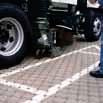
2 TABLE OF CONTENTS 1. INTRODUCTION SUPPORTING DOCUMENTS DESIGN POPULATION WATER SUPPLY AND DISTRIBUTION WATER SERVICING DESIGN CRITERIA FIREFIGHTING AND INTERNAL WATER DISTRIBUTION SYSTEM SANITARY SERVICING SANITARY DESIGN CRITERIA INTERNAL SANITARY SEWER SYSTEM STORMWATER MANAGEMENT ANALYSIS METHODOLOGY EXISTING CONDITIONS PROPOSED STORM DRAINAGE SYSTEM STORMWATER QUANTITY CONTROL STORMWATER QUALITY CONTROL PERMANENT QUALITY CONTROL DURING CONSTRUCTION ACTIVITIES WATER BALANCE PHOSPHORUS CALCULATIONS MAINTENANCE BRENTWOOD CHAMBER PERMEABLE PAVERS SECONDARY UTILITIES CONCLUSIONS Functional Servicing Report and SWM Report, Dec White Crescent, Barrie 18058
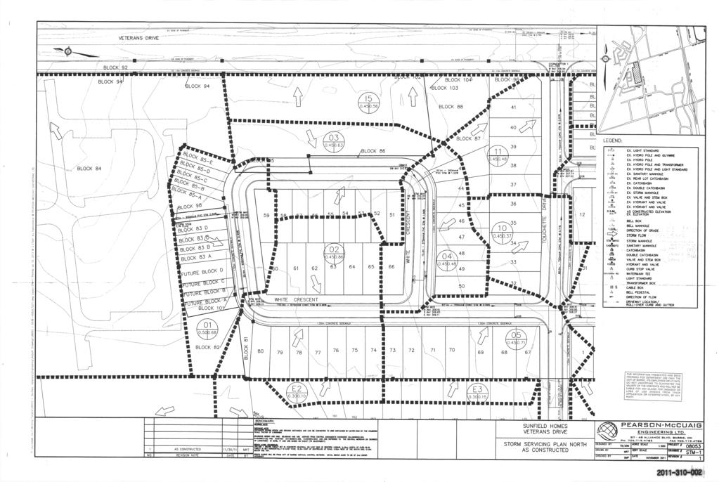
3 APPENDICES Appendix A Water Servicing Calculations Appendix B Sanitary Servicing Calculations Appendix C Stormwater Management Calculations Appendix D Water Balance Calculations Appendix E Phosphorus Calculations Appendix F Engineering Drawings LIST OF FIGURES & DRAWINGS Figure 1 Location Plan SS-1 Site Servicing Plan SG-1 Site Grading Plan STM-1 Post-Development Storm Drainage Plan STM-1 Storm Servicing Plan North As Constructed Pearson-McCuaig, November 2011 Functional Servicing Report and SWM Report, Dec White Crescent, Barrie 18058
4 FUNCTIONAL SERVICING REPORT AND SWM REPORT 104 WHITE CRESCENT - BARRIE 1. Introduction PEARSON Engineering Ltd. has been retained by Michler Holdings Ltd. (Client) to prepare a Functional Servicing Report (FSR) and Stormwater Management (SWM) Report in support of the proposed 8 Unit Townhouse Development located at 104 White Crescent in the City of Barrie (City), County of Simcoe (County). The subject property is approximately 0.21 ha in size and is currently a vacant lot. The existing site drains to the east sloping towards Veterans Drive at an average slope of 0.6%. The Townhouse Units will front onto Veterans Drive with the driveway entrance connecting onto White Crescent. The location of the site can be seen on Figure 1. This FSR and SWM Report assesses the existing municipal infrastructure in the vicinity of the Project, the onsite SWM facilities and internal services required to service the proposed Project. 2. Supporting Documents The following documents have been referenced in the preparation of this report: Ministry of the Environment, Design Guidelines for Sewage Works 2008 Ministry of the Environment, Design Guidelines for Drinking-Water Systems Ministry of the Environment, Stormwater Management Planning and Design Manual, March 2003 City of Barrie, Sanitary Sewage Collection System Policies and Design Guidelines September 2012 City of Barrie, Water Distribution Specification February 2005 City of Barrie, Storm Drainage and Stormwater Management Policies and Design Guidelines November Design Population The proposed development includes 8 townhouse residential units. Based on the average unit size, a design population of 2.34 persons per unit has been selected as per City of Barrie Standards. This results in a maximum projected design population of 19 persons. Refer to Appendix A for calculations. 4. Water Supply and Distribution 4.1. Water Servicing Design Criteria The site is to have a total population of 19 persons. Utilizing the MOE Guidelines for domestic water use of 225 L/capita/day, an Average Day Demand (ADD) of 0.05 L/sec is required. A Peak Rate factor of 4.13 is used in calculating a Peak Hour Demand (PHD) of 0.20 L/sec for the development. Calculations for the domestic water requirements for the site can be found in Appendix A. Functional Servicing Report and SWM Report, Dec White Crescent, Barrie 18058

5 PEARSON ENGINEERING LTD. PEARSONENG.COM PH
6 4.2. Firefighting and Internal Water Distribution System Each townhouse unit will be serviced separately with a 25 mm diameter domestic water service. The proposed services will connect into the proposed internal 100 mm diameter watermain which will connect into the existing 300 mm diameter municipal watermain on White Crescent. Locations of the water service connections are shown on the Site Servicing DWG SS-1. There is an existing fire hydrant on Veterans Drive in front of the project site. It is proposed that this hydrant be utilized for fire servicing of the project site. We suggest that the City review the existing City watermain distribution system with respect to the City's water treatment and supply capacities for both domestic and fire service for this development and confirm that pressure and capacity allocation is available. 5. Sanitary Servicing 5.1. Sanitary Design Criteria The site is to have a total population of 19 persons. Utilizing the City of Barrie Guidelines for domestic sewer use of 225 L/capita/day, an Average Daily Flow (ADF) of 0.05 L/s is calculated. Including extraneous flows and using a Peaking Factor of 4.0 for this project, a Peak Flow of 0.22 L/s is calculated for the project site. The proposed sanitary sewer will be designed to convey the sanitary design flows for the project to the existing 250 mm diameter sanitary sewer on White Crescent. Sanitary design flow calculations can be found in Appendix B Internal Sanitary Sewer System The sanitary sewers will be constructed in accordance with the City of Barrie s Engineering Standards and the MOE guidelines in order to service the Project. Each townhouse unit will have a service lateral of a minimum diameter of 100 mm and will be designed to meet minimum design grades and the required minimum and maximum velocities under flow conditions. The laterals will connect into an internal 200 mm diameter sanitary sewer and outlet onto the existing 250 mm diameter sanitary sewer on White Crescent. The existing 200 mm diameter sanitary sewer on White Crescent has a capacity of 59 L/s at a slope of 0.97%. The proposed peak flow is 0.4% of the existing capacity and therefore the existing 250 mm diameter sanitary sewer is sufficient to convey the sanitary design flows. Refer to the Site Servicing DWG SS-1 for the proposed sanitary servicing layout. We suggest that the City review the sanitary design flow from this Project with respect to the City s sanitary treatment capacities and confirm that capacity allocation is available for this development. Functional Servicing Report and SWM Report, Dec White Crescent, Barrie 18058
7 6. Stormwater Management A key component of the development is the need to address environmental and related SWM issues. These are examined in a framework aimed at meeting the City and MOECC requirements. SWM parameters have evolved from an understanding of the location and sensitivity of the site's natural systems. This FSR and SWM Report focuses on the necessary measures to satisfy the MOECC's SWM requirements. It is understood the objectives of the SWM plan are to: Protect life and property from flooding and erosion Maintain water quality for ecological integrity, recreational opportunities etc. Protect and maintain groundwater flow regime(s). Protect aquatic and fishery communities and habitats. Maintain and protect significant natural features Analysis Methodology The design of the SWM Facilities for this site has been conducted in accordance with: The Ministry of the Environment Stormwater Management Planning and Design Manual, March 2003 City of Barrie, Storm Drainage and Stormwater Management Policies and Design Guidelines 30 November 2009 In order to design the facilities to meet these requirements, it is essential to select the appropriate modeling methodology for the storm system design. Given the size of the site, the Modified Rational Method is appropriate for the design for the SWM system Existing Conditions The project site is approximately 0.21 hectares in size and is currently a vacant lot with a large gravel area. The majority of the site's stormwater flows from west to east overland at approximately 0.6%. Flows from the site either enter directly into the existing storm sewer system on Veterans Drive or flow through the adjacent lots on Touchette Drive prior to entering the storm sewer system. The storm sewer systems on White Crescent, Touchette Drive and Veterans Drive ultimately outlet into the downstream SWM pond. According to the report completed by Soil Engineers Ltd in January 2004, beneath a layer of topsoil, 15 to 35 cm thick, a stratum of silty sand till extends to the maximum investigated depths in 6 boreholes. Occasional deposits of fine sand and silty clay were found below the silty sand till deposit. According to their findings, this soil is characterized as having high frost susceptibility, low water erodibility, and is relatively permeable. Functional Servicing Report and SWM Report, Dec White Crescent, Barrie 18058
8 According to the Development Charge Background Study for the Whiskey Creek Stormwater Management Works, by Watson & Associates, April 29, 2011, the design of the downstream SWM Pond has allocated a runoff coefficient of 0.48 for the project site. However, according to the Sunfield Homes Veterans Drive, Storm Servicing Plan North As Constructed, by Pearson- McCuaig Engineering Ltd., November 2011, the surrounding storm sewers have been designed to allow the site to contribute flows towards White Crescent, Veterans Drive, and through the adjacent lots on Touchette Drive utilizing a runoff coefficient of As such, allowable flows for the 2 and 5 year storm event have been designed to the 0.45 runoff coefficient to ensure sufficient capacity within the storm sewer and the 10 to 100 year allowable flows have been designed to the 0.48 runoff coefficient. Allowable peak flows for the site can be seen in Table 1 below. Detailed calculations for the existing drainage conditions can be found in Appendix A. Table 1: Allowable Peak Flows 2 Year Storm 5 Year Storm 10 Year Storm 25 Year Storm 50 Year Storm 100 Year Storm Total Flow to White Crescent (m 3 /s) Total Flow to Veterans Drive (m 3 /s) Total Flow to Adjacent Lots (m 3 /s) Total Allowable Flow (m 3 /s) Proposed Storm Drainage System The proposed development includes construction of 8 Townhouse Units with a curbed asphalt parking area located west of the proposed buildings. The proposed drainage from the majority of the development will flow overland towards permeable pavers located within the parking stalls on the south side of the parking lot. Stormwater that is captured within the perforated pipe at the base of the permeable pavers as well as that which is captured within the catch basin located within the permeable pavers will direct stormwater runoff into the storm sewer system. An orifice tube will be located south of MH1, restricting flows into the underground storage chambers. Stormwater from the east side of the townhouse units will drain via overland flow uncontrolled towards Veterans Drive, and a small area of sidewalk and landscape area on the south side of the site will flow uncontrolled easterly towards existing residential units on Touchette Drive. In the event of a major storm, defined as storms larger than the 5-year event, the storm sewer will surcharge, forcing stormwater to the site's surface. All major storm flow will be contained within the curbed parking lot and conveyed to White Crescent through the driveway entrance. The proposed drainage patterns can be seen on the Post Development Storm Catchment Plan DWG STM-1 under Appendix F Stormwater Quantity Control The existing stormwater management features have been previously designed assuming the Project Site would have a runoff coefficient of The calculated post-development runoff coefficient of 0.72 is greater than the allowable runoff coefficient, and so considerations were taken to reduce post development peak flows to allowable values. Functional Servicing Report and SWM Report, Dec White Crescent, Barrie 18058
9 Quantity control for the site will be achieved through the use of an orifice tube, underground storage chambers and surface ponding. Calculations indicate that 36 m 3 of storage is required for the 100-year storm event. A 75 mm diameter orifice tube is located downstream of MH1 restricting storms up to the 5 year flow into 28 Brentwood ST-24 underground storage units located in the west parking area. Storms greater than the 5 year storm event will surcharge to the surface and storage will be provided in 30 m 3 in surface ponding. The driveway entrance is used as an emergency overflow weir directing flows towards White Crescent. Given that the minimum orifice size is 75 mm as per City of Barrie Standards, the flows towards White Crescent and the total flows from the site are slightly more than allowable. However, as per the Whiskey Creek 2002 DC Background Study, revised April 2011, the total area contributing to the downstream SWM Pond is ha. As the Project site comprises only 0.2% of this area, the additional flows from the site are negligible and will easily be accommodated within the downstream storm pond. The controlled post development peak flows are shown in Table 2. Detailed calculations can be seen in Appendix A. Table 2: Post Development Peak Flows 2 Year Storm 5 Year Storm 10 Year Storm 25 Year Storm 50 Year Storm 100 Year Storm Controlled Area (To White Cres.) (m 3 /s) Uncontrolled Flow to White Crescent (m 3 /s) Uncontrolled Flow to Veterans Drive (m 3 /s) Uncontrolled Flow to Adjacent Lots (m 3 /s) Total Site (m 3 /s) Comparing flows from Table 1 and Table 2, the post development flows are slightly above the allowable given the limitation of the 75 mm diameter orifice. However, the flows are considered negligible given the small quantity of flow that the site produces Stormwater Quality Control The Ministry of the Environment and Climate Change (MOECC) in March 2003 issued a Stormwater Management Planning and Design Manual. This manual has been adopted by a variety of agencies including the City of Barrie. The objective of our Stormwater Quality Control will be to ensure Enhanced Protection quality control as stated in the MOECC manual. To achieve enhanced protection, permanent and temporary control of erosion and sediment transport are proposed and are discussed in the following sections. The majority of the proposed drainage from the parking lot area will be conveyed to a system of permeable pavers complete with a perforated underdrain which will convey stormwater to the storm sewer system designed to convey the 5 year storm event. Functional Servicing Report and SWM Report, Dec White Crescent, Barrie 18058
10 Runoff from rooftop of the west side of the proposed townhouse units will flow towards underground infiltration units located within the grassed area on the west side of the site. An overflow spout will be provided on the downspouts to direct water overland in the event that the system surcharges. Low Impact Development features are an emerging technology and therefore the guidelines listed above are subject to change. As standard details and specifications are still being developed, all details and locations are to be reviewed and approved by the City Permanent Quality Control The developments active parking facilities pose a risk to stormwater quality through the collection of grit, salt, sand and oils on the paved surfaces. The existing downstream SWM Pond has been sized to provide quality/erosion control for the project site area for 70% long-term suspended solids removal assuming a runoff coefficient of 0.48 as per Table 3.2 in the MOECC Stormwater Management Planning and Design Manual, March The site has a runoff coefficient of 0.72, however the size of the site is small and thus only an additional 26.2 m 3 would be required to treat the site to Enhanced 80% long-term removal within the downstream SWM Pond. Given the size of the downstream SWM pond and the pre-treatment provided through permeable pavers and rooftop infiltration, this volume requirement is nominal and can easily be accommodated within the downstream SWM pond, therefore, no additional quality control measures are proposed During Construction Activities During construction, earth grading and excavation will create the potential for soil erosion and sedimentation. It is imperative that effective environmental and sedimentation controls are in place and maintained throughout the duration of construction activities to ensure stormwater runoff's quality. Therefore, the following recommendations shall be implemented and maintained during construction to achieve acceptable stormwater runoff quality: Installation of silt fence along the entire perimeter of the site to reduce sediment migration onto surrounding properties. Installation of a construction entrance mat to minimize transportation of sediment onto roadways. Restoration of exposed surfaces with vegetative and non-vegetative material as soon as construction schedules permit. The duration in which surfaces are disturbed/exposed shall not exceed 30 days. Reduce stormwater drainage velocities where possible. Minimize the amount of existing vegetation removed Water Balance Since the post-development state will increase the imperviousness of the site, considerations were taken in regards to groundwater recharge. According to the report completed by Soil Engineers Ltd in January 2004, the site consists silty sand till. This soil is characterized as being relatively permeable. Functional Servicing Report and SWM Report, Dec White Crescent, Barrie 18058
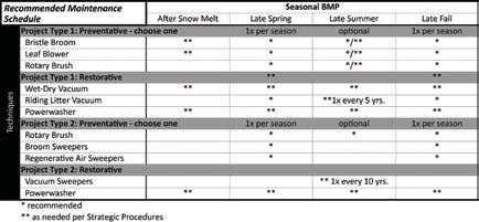
11 Calculations were completed utilizing pre-development to post development volume requirements as well as the City of Barrie minimum infiltration volume requirements of 5 mm over the total area of the site. The City of Barrie values govern the infiltration requirements and thus 11 m 3 of storage is required. Stormwater runoff from the west half of the rooftop of the building will be directed into 26 underground Brentwood ST-36 infiltration units located in the grassed area on the west side of the site to provide 11.7 m 3 of infiltration storage. An emergency overflow stormwater pipe will be installed at the base of the roof leaders to prevent the back up of storm flows towards the building in the event that the system surcharges. Detailed calculations can be found in Appendix D Phosphorus Calculations Local conservation authorities have determined the importance of reducing phosphorus levels in water courses in this area. The reduction was based on conservative values derived from the LSRCA. As such, best efforts are to be employed in order to reduce phosphorus levels to predevelopment levels or better. The existing site generates approximately 0.01 kg of phosphorus annually and the proposed Project will generate approximately 0.28 kg of phosphorus annually if uncontrolled. Best efforts will be used in order to reduce the phosphorus loading as much as is reasonably possible. To minimize the amount of phosphorus discharged from the site, a treatment train approach is to be utilized. Rooftop runoff from the west side of the proposed buildings will be directed to underground infiltration units and parking lot runoff will be conveyed to permeable paver units. Stormwater from the site will then flow through the storm sewer system and into the downstream wet pond. According to the LSRCA Phosphorus Loading Development Tool, the typical phosphorus reduction is 60% for infiltration, 45% for permeable pavers and 63% for a wet pond. The following chart details the anticipated phosphorous loadings for the pre and postdevelopment conditions. Table 3: Phosphorus Loadings Total P (kg) Pre-Development 0.01 Uncontrolled Post Development Controlled Post Development Detailed calculations can be found in Appendix E Maintenance Brentwood Chamber The Brentwood Chambers are proposed to provide 11 m 3 of underground infiltration volume and 7 m 3 of storage volume. The chambers should be inspected every 6 months and after each major rainfall event during the first year to ensure that the storm tanks are free of any debris. In subsequent years, the chambers should be inspected semi-annually, or more if deemed necessary for this specific site. Functional Servicing Report and SWM Report, Dec White Crescent, Barrie 18058

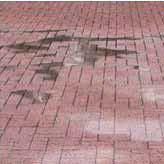
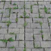
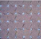
12 If the average depth of sediment exceeds 3 inches throughout the length of the chamber, a cleanout should be performed. Maintenance should be executed using a vacuum pump truck to evacuate sediment and debris from system. The system should be flushed with clean water, with care taken to avoid extreme direct water pressures and is to be performed in dry weather. Material removed from the unit will be disposed of in a similar manner to that of other stormwater management facilities. The owner should keep a Record of Maintenance Book to log inspection results and cleanout frequency. The maintenance manual from the manufacturer is included in Appendix D Permeable Pavers Permeable pavement requires regular inspection and maintenance to ensure that it functions properly. The limiting factor for permeable pavers is clogging within the aggregate layers, filler, or underdrain. The pavers themselves can be reused. Annual inspections of permeable pavement should be conducted in the spring to ensure continued infiltration performance. These inspections should check for spilling or deterioration and investigate whether water is draining between storms. The pavement reservoir should drain completely within 48 hours of the end of the storm event. 7. Secondary Utilities Given the location of the subject site, it is anticipated that secondary utilities (hydro, cable, phone and gas) will be available to service the site. This will be investigated further in the detailed design stage. 8. Conclusions The proposed development will require the connection of the watermain services and the sanitary services to White Crescent. Storm services for the development will be conveyed to White Crescent. The SWM design for this site takes into account the existing conditions and is contained within the site's boundaries. Permeable pavers and rooftop infiltration are proposed to provide phosphorus reduction and water balance. Quality control will be provided within the downstream SWM Pond. The analysis and conceptual design outlined in this report demonstrates that the servicing is feasible. All of which is respectfully submitted, Pearson Engineering Ltd. Meghan Whynot, P. Eng Design Engineer Mike Dejean, P.Eng. Manager of Engineering Services Functional Servicing Report and SWM Report, Dec White Crescent, Barrie 18058
13 APPENDIX A WATER SERVICING CALCULATIONS Functional Servicing Report and SWM Report, Dec A 104 White Crescent, Barrie 18058
14 104 White Crescent - Barrie, Ontario Water Flow Calculations Design Criteria Demand per capita (Q): Peak Rate Factor (Max. Hour) Max. Day Factor 225 L/cap/day 4.13 (Table 3-1: Peaking Factors, MOE Design Guidelines for Drinking-Water Systems) 2.75 (Table 3-1: Peaking Factors, MOE Design Guidelines for Drinking-Water Systems) Site Data Description Density Units Flow Rate Peaking Factors Apartments 2.34 people/unit 8 units 225 L/cap/d MAX DAY FACTOR* 2.75 Calculate Population Pop. Apartments = 2.34 x 8 Pop. Total = 19 people Calculate Average Day Demand (ADD) ADD = 225 x 19 ADD = 4212 L/day ADD = 0.05 L/s Calculate Max Day Flow MDF = 0.05 x 2.75 MDF = 0.13 L/s Calculate Peak Hour Demand PHD = 0.05 x 4.13 PHD = 0.20 L/s PEAK RATE FACTOR* 4.13 *From MOE Manual based on Population of 500-1,000
15 APPENDIX B SANITARY SERVICING CALCULATIONS Functional Servicing Report and SWM Report, Dec B 104 White Crescent, Barrie 18058
16 Design Criteria Flow per capita (Q): 225 L/cap/day Peak Flow Qp = P * Q * M / I * A Peaking Factor (Harmon Formula) M = 1 + ( 14 / ( 4 + ( P / 1000 ) ^ 0.5 ) ) Where: 2 <= "M" <= 4 Site Data Description Density Units Flow Rate Townhouse Units 2.34 people/unit 8 units 225 L/cap/d Calculate Population Pop. Apartments = 2.34 x 8 Pop. = 19 people Calculate Average Daily Flows ADF (L/s) = 225 x 19 ADF (L/s) = 4212 L/day ADF (L/s) = 0.05 L/s Calculate Peaking Factor M = * 0.12 M = 4.40 Use Max Peaking Factor White Crescent - Barrie, Ontario Sanitary Flow Calculations , Calculate Peak Flow Qp = 0.05 x 4.00 = 0.20 L/s Infiltration Allowance City of Barrie extraneous flow rate = 0.10 L/s/ha Area of Site = 0.21 ha Extraneous Flows = 0.02 L/s Qp (Inc. Infiltration Allowance) = 0.22 L/s
17 APPENDIX C STORMWATER MANAGEMENT CALCULATIONS Functional Servicing Report and SWM Report, Dec C 104 White Crescent, Barrie 18058
18 104 White Crescent, Barrie, Ontario Calculation of Runoff Coefficients Runoff Coefficient = Weighted Surface Cover = *Grass Asphalt Building Gravel Concrete Runoff Coefficient PRE Total Area Area Area Area Area Area DEVELOPMENT (m 2 ) (m 2 ) (m 2 ) (m 2 ) (m 2 ) (m 2 ) Pre Total POST Total Area Area Area Area Area Area DEVELOPMENT (m 2 ) (m 2 ) (m 2 ) (m 2 ) (m 2 ) (m 2 ) Post Total *Value taken from Soil Engineers Ltd. Soil Report, January SWM 12/20/2018
19 104 White Crescent, Barrie, Ontario Allowable Peak Flows City of Barrie Storm (yrs) Coeff A Coeff B Coeff C Modified Rational Method Q = C i CIA / Where: Q - Flow Rate (m 3 /s) Ci - Peaking Coefficient C - Rational Method Runoff Coefficient I - Storm Intensity (mm/hr) A - Area (ha.) Area Number 1- To White Cres. 2- To Veteran's Drive 3-To Adjacent Lots Area 0.03 ha 0.14 ha 0.05 ha Runoff Coefficient (2 and 5 Year) Runoff Coefficient (10 to 100 Year) Time of Concentration 10 min 10 min 10 min Return Rate 2 year 2 year 2 year Peaking Coefficient (C i ) Rainfall Intensity 83.1 mm/hr 83.1 mm/hr 83.1 mm/hr Pre-Development Peak Flow m 3 /s m 3 /s m 3 /s Return Rate 5 year 5 year 5 year Peaking Coefficient (C i ) Rainfall Intensity mm/hr mm/hr mm/hr Pre-Development Peak Flow m 3 /s m 3 /s m 3 /s Return Rate 10 year 10 year 10 year Peaking Coefficient (C i ) Rainfall Intensity mm/hr mm/hr mm/hr Pre-Development Peak Flow m 3 /s m 3 /s m 3 /s Return Rate 25 year 25 year 25 year Peaking Coefficient (C i ) Rainfall Intensity mm/hr mm/hr mm/hr Pre-Development Peak Flow m 3 /s m 3 /s m 3 /s Return Rate 50 year 50 year 50 year Peaking Coefficient (C i ) Rainfall Intensity mm/hr mm/hr mm/hr Pre-Development Peak Flow m 3 /s m 3 /s m 3 /s Return Rate 100 year 100 year 100 year Peaking Coefficient (C i ) Rainfall Intensity mm/hr mm/hr mm/hr Pre-Development Peak Flow m 3 /s m 3 /s m 3 /s SWM 12/20/2018
20 104 White Crescent, Barrie, Ontario Post-Development Peak Flows City of Barrie Modified Rational Method Storm (yrs) Coeff A Coeff B Coeff C Q = C i CIA / Where: Q - Flow Rate (m 3 /s) Ci - Peaking Coefficient C - Rational Method Runoff Coefficient I - Storm Intensity (mm/hr) A - Area (ha.) Uncontrolled to White Uncontrolled to Adjacent Area to Quantity Control Uncontrolled to Veterans Cres. Lots Area Number Area 0.13 ha ha 0.06 ha 0.01 ha Runoff Coefficient Time of Concentration 10 min 10 min 10 min 10 min Return Rate 2 year 2 year 2 year 2 year Peaking Coefficient (C i ) Rainfall Intensity Post-Development Peak Flow 0.02 m 3 /s m 3 /s m 3 /s m 3 /s Return Rate 5 year 5 year 5 year 5 year Peaking Coefficient (C i ) Rainfall Intensity Post-Development Peak Flow 0.03 m 3 /s m 3 /s m 3 /s m 3 /s Return Rate 10 year 10 year 10 year 10 year Peaking Coefficient (C i ) Rainfall Intensity Post-Development Peak Flow 0.04 m 3 /s m 3 /s m 3 /s m 3 /s Return Rate 25 year 25 year 25 year 25 year Peaking Coefficient (C i ) Rainfall Intensity Post-Development Peak Flow 0.04 m 3 /s m 3 /s m 3 /s m 3 /s Return Rate 50 year 50 year 50 year 50 year Peaking Coefficient (C i ) Rainfall Intensity Post-Development Peak Flow 0.05 m 3 /s m 3 /s m 3 /s m 3 /s Return Rate 100 year 100 year 100 year 100 year Peaking Coefficient (C i ) Rainfall Intensity Post-Development Peak Flow 0.05 m 3 /s m 3 /s m 3 /s m 3 /s SWM 12/20/2018
21 104 White Crescent, Barrie, Ontario Quantity Control Volume Calculations Modified Rational Method Parameters SWM Pond Design Input DATE: 20-Dec-18 FILE: CONTRACT/PROJECT: 104 White Crescent COMPLETED BY: MKRW Pre Development Area (ha) Post Development Area (ha) Time of Concentration (min) Time Increments (min) Pre Development Runoff Coefficient Post Development Runoff Coefficient Storm (yrs) Chicago Storm Coefficient Chicago Storm Coefficient Chicago Storm Coefficient Allowable Outflow * A B C (m3/s) ** *Runoff Coefficient for 2 and 5 year storm *Runoff Coefficient for 10 to 100 year storm Note: Refer to page Calculation of Runoff Coefficients for detailed calculations of Modified Rational Method parameters Allowable Runoff Rate Year 5 Year 10 Year 25 Year 50 Year 100 Year C C i I Results A Storm Storage Time Post Development Runoff Coefficient Q Event m 3 min Note: Q= CC iia Rainfall Station Barrie Note: Storage volume calculated as per Hydrology Handbook, Second Edition, American Society of Civil Engineers, Year 5 Year 10 Year 25 Year 50 Year 100 Year Time Intensity Inflow Outflow Storage Difference Intensity Inflow Outflow Storage Difference Intensity Inflow Outflow Storage Difference Intensity Inflow Outflow Storage Difference Intensity Inflow Outflow Storage Difference Intensity Inflow Outflow Storage Difference (min) mm/hr m 3 /s m 3 /s m 3 mm/hr m 3 /s m 3 /s m 3 mm/hr m 3 /s m 3 /s m 3 mm/hr m 3 /s m 3 /s m 3 mm/hr m 3 /s m 3 /s m 3 mm/hr m 3 /s m 3 /s m Maximum Storage Volume SWM 12/20/2018
22 Calculation of Runoff Coefficients Stage-Storage-Discharge Table Orifice 1 Orifice 1 Weir Weir Elevation Area Volume Cum. Vol. Head Flow Head Flow Total Flow (m) (m 2 ) (m 3 ) (m 3 ) (m) (m 3 /s) (m) (m 3 /s) (m 3 /s) Diameter Invert Elevation Orifice Constant Orifice Centroid Orifice Flow Formula Orifice 1 75 mm π(D/2000) 2 x(2x9.81xh) 0.5 Width Major Storm Control Weir 5.60 m Invert of Weir m Weir Flow Formula 1.7WH SWM 12/20/2018
23 104 White Crescent, Barrie, Ontario Quality Control Calculations Given that the downstream SWM Pond is designed to provide 70% long-term S.S. removal for the site at a runoff coefficient of 0.48 Storage Volume accounted for in pond = 21.9 m 3 from Table 3.2 Water Quality Storage Requirements Volume Requred for Enhanced long-term S.S. removal in wet pond = 48.1 m 3 from Table 3.2 Water Quality Storage Requirements Deficit storage in wet pond = 26.2 m 3 Therefore 26.9m 3 of storage is required within the downstream SWM pond to provide Enhanced long term S.S. removal SWM 12/20/2018
24 104 White Crescent, Barrie, Ontario Permeable Pavers Sizing Calculations Infiltration volumes from MOE Stormwater Management Planning and Design Manual to size Bioretention Filter Table 3.2 Water Quality Storage Requirements are as follows: Design Area Total = 0.21 ha Total Imperviousness = 71% Storage Volume = 35 m 3 /ha (Enhanced 80% long-term S.S. removal) Area 1 Storage Volume Required = 0.21 x 35.4 = 7.4 m 3 Find Storage Volume provided in Permeable Pavers: Area of Pavers (A) = 17.0 m 2 Depth of Trench (d) = 1.10 m Storage Volume (V) = 0.4(A x d) = 7.5 m 3 Use Equation 4.12 to find Area of Permeable Pavers: Depth of Controlling Filter Medium (d) = 1.10 m Coefficient of Permeability of the = 45.0 mm/hr Controlling Filter Media (k) Operating Head of Water On the Filter (h) = 0.18 m Design Drawdown Time (t) = 36 hr Surface Area Of Filter (A) = 1000Vd k(h+d)t = 4.0 m 2 Required Provided Area 1 Surface Area = 4.0 m m SWM 12/20/2018


25
26


27


28
29
30 When we take care of the earth, it will ultimately take care of us UNILOCK 2011 Hengestone Holdings, Inc. Printed July, 2011.

 Void Space 96.")
31 Sub-Surface Stormwater Storage System Product: ST-24 StormTank Stormwater Storage System is a high-void, high strength, affordable alternative to crushed stone, concrete structures, or pipe chambers. Use of StormTank reclaims valuable surface space for better surface usage such as recreational areas, parking lots or buildings. StormTank module design provides the maximum storage volume while minimizing the installation footprint to reduce construction costs. The open module design, with no partitions or walls between modules, allows for easy inspection and cleaning. Technical Data Nominal Specifications Size 36 x18 x24 (914x457x610 mm) Void Space 96.0% Module Storage 8.66 cf (0.25 m 3 ) Installed Storage cf (0.32 m 3 ) Weight lbs. (12 kg) Notes: Installed storage assumes 6 of stone below, 12 stone above and 40% porosity for the stone plus the module volume. Shipping Information Description Packaged Quantity Packaged Weight lbs. (kg) Top/Bottom Platens 84 / skid 568 (258) 126 / skid 853 (387) Side Panels (3ft length) 90 / skid 367 (166) Columns 336 / skid 616 (279) Manufacturer: Mailing Address: P.O. Box 605, Reading, PA Shipping Address 610 Morgantown Road, Reading, PA Phone: Fax: stormwater@brentwoodindustries.com Website: Brentwood Industries StormTank is a registered trademark of Brentwood Industries Disclaimer: Brentwood Industries (Brentwood) assumes no liability for the accuracy or completeness of this information or for the ultimate use by the purchaser. Brentwood Industries disclaims any and all other warranties, expressed or implied with respect to any service or deliverable other than those expressly provided in this (section, paragraph, quotation, proposal, etc.) including without limitation any implied warranty of merchantability or fitness for a particular purpose This document should not be construed as engineering advice.
32 APPENDIX D WATER BALANCE CALCULATIONS Functional Servicing Report and SWM Report, Dec D 104 White Crescent, Barrie 18058
33 104 White Crescent, Barrie, Ontario Pre Development Water Balance Site Catchment Designation Grassed Gravel Total Area Pervious Area Impervious Area Infiltration Factors Topography Infiltration Factor (From MOE Table 3.1 for Rolling Land) Soil Infiltration Factor (From MOE Table 3.1 for Medium combinations of clay and loam) Land Cover Infiltration Factor MOE Infiltration Factor Actual Infiltration Factor Run-Off Coeffiecient Runoff from Impervious Surfaces Inputs (per Unit Area) Precipitation (Precipitation values from Lake Simcoe Climate Data Values, Lovers Creek Subwatershed) Run-On Other Inputs Total Inputs Outputs (per Unit Area) Precipitation Surplus Net Surplus Evapotranspiration (Evapotranspiration values for pervious area from Lake Simcoe Climate Data Values, Lovers Creek Subwatershed for impervious areas is the difference between the total precipitation and the net surplus) Infiltration Rooftop Infiltration Total Infiltration Runoff Pervious Areas Runoff Impervious Areas Total Runoff Total Outputs Difference (Inputs - Outputs) Inputs (Volumes) Precipitation Run-On Other Inputs Total Inputs Outputs (Volumes) Precipitation Surplus Net Surplus Evapotranspiration Infiltration Rooftop Infiltration Total Infiltration Runoff Pervious Areas Runoff Impervious Areas Total Runoff Total Outputs Difference (Inputs - Outputs) Note: Highlighted cells are input cells SWM 12/20/2018
34 104 White Crescent, Barrie, Ontario Post Development Water Balance (No Infiltration) Site Catchment Designation Grassed Paved Building Total Area Pervious Area Impervious Area Infiltration Factors Topography Infiltration Factor (From MOE Table 3.1 for Rolling Land) Soil Infiltration Factor (From MOE Table 3.1 for Medium combinations of clay and loam) Land Cover Infiltration Factor MOE Infiltration Factor Actual Infiltration Factor Run-Off Coeffiecient Runoff from Impervious Surfaces Inputs (per Unit Area) Precipitation (Precipitation values from Lake Simcoe Climate Data Values, Lovers Creek Subwatershed) Run-On Other Inputs Total Inputs Outputs (per Unit Area) Precipitation Surplus Net Surplus Evapotranspiration (Evapotranspiration values for pervious area from Lake Simcoe Climate Data Values, Lovers Creek Subwatershed for impervious areas is the difference between the total precipitation and the net surplus) Infiltration Rooftop Infiltration Total Infiltration Runoff Pervious Areas Runoff Impervious Areas Total Runoff Total Outputs Difference (Inputs - Outputs) Inputs (Volumes) Precipitation Run-On Other Inputs Total Inputs Outputs (Volumes) Precipitation Surplus Net Surplus Evapotranspiration Infiltration Rooftop Infiltration Total Infiltration Runoff Pervious Areas Runoff Impervious Areas Total Runoff Total Outputs Difference (Inputs - Outputs) Note: Highlighted cells are input cells SWM 12/20/2018
35 104 White Crescent, Barrie, Ontario Post Development Water Balance (With Infiltration) Site Catchment Designation Building (with Grassed Paved Infiltration) Total Area Pervious Area Impervious Area Infiltration Factors Topography Infiltration Factor (From MOE Table 3.1 for Rolling Land) Soil Infiltration Factor (From MOE Table 3.1 for Medium combinations of clay and loam) Land Cover Infiltration Factor MOE Infiltration Factor Actual Infiltration Factor Run-Off Coeffiecient Runoff from Impervious Surfaces Inputs (per Unit Area) Precipitation (Precipitation values from Lake Simcoe Climate Data Values, Lovers Creek Subwatershed) Run-On Other Inputs Total Inputs Outputs (per Unit Area) Precipitation Surplus Net Surplus Evapotranspiration Infiltration Rooftop Infiltration Total Infiltration (Evapotranspiration values for pervious area from Lake Simcoe Climate Data Values, Lovers Creek Subwatershed for impervious areas is the difference between the total precipitation and the net surplus) Depth of rainfall over the rooftop required to be infiltrated to achieve water balance. Runoff Pervious Areas Runoff Impervious Areas Total Runoff Total Outputs Difference (Inputs - Outputs) Inputs (Volumes) Precipitation Run-On Other Inputs Total Inputs Outputs (Volumes) Precipitation Surplus Net Surplus Evapotranspiration Infiltration Rooftop Infiltration Total Infiltration Runoff Pervious Areas Runoff Impervious Areas Total Runoff Total Outputs Difference (Inputs - Outputs) Note: Highlighted cells are input cells SWM 12/20/2018
36 104 White Crescent, Barrie, Ontario Water Balance Calculations Annual Rainfall Depth Req'd Req'd Rainfall Depth = 23.5 mm (From Post-Development Water Balance (With Infiltration)) Find Percent of Annual Rainfall that Req'd Rainfall Depth represents Annual Rainfall for Study Area = % Annual Rainfall = = mm (Precipitation values from Lake Simcoe Climate Data Values, Lovers Creek Subwatershed) 23.5 mm 914 mm 3% From MOE Figure C-2, 3% of annual rainfall occurs for storm events of 15 mm or less. Find storage volume required for rainfall events of 15 mm to Rooftop Infiltration Gallery Roof Top Area = 280 m 2 Rainfall Depth = 15 mm Storage Volume Req'd = A x D = 280 x 15 = 4 m 3 Minimum Infiltration Volume as per City of Barrie Storm Drainage and Stormwater Management Policies and Design Guidelines Section is as follows: Storage Volume Req'd = = = Site Area x 5 mm 2106 x m 3 Therefore,City of Barrie guidelines governs over water balance/infiltration requirements. Roof Top Infiltration Infiltrate the 50 mm Storm Event Area of Rooftop to be infiltrated = 226 m 2 (East Half of Roof) Amount to be Infiltrated = 50 mm = Volume = Area x Depth = 226 x 50 = 11.3 m 3 Volume in Brentwood ST-36 Storage Tanks = 0.45 m 3 # of Storage Tanks Required = 25.1 = 26 Therefore water balance for the site is achieved. Volume Provided = 11.7 m SWM 12/20/2018

 Void Space 97.")
37 Sub-Surface Stormwater Storage System Product: ST-36 StormTank Stormwater Storage System is a high-void, high strength, affordable alternative to crushed stone, concrete structures, or pipe chambers. Use of StormTank reclaims valuable surface space for better surface usage such as recreational areas, parking lots or buildings. StormTank module design provides the maximum storage volume while minimizing the installation footprint to reduce construction costs. The open module design, with no partitions or walls between modules, allows for easy inspection and cleaning. Technical Data Nominal Specifications Size 36 x18 x36 (914x457x914 mm) Void Space 97.0% Module Storage cf (0.37 m 3 ) Installed Storage cf (0.45 m 3 ) Weight lbs. (15 kg) Notes: Installed storage assumes 6 of stone below, 12 stone above and 40% porosity for the stone plus the module volume. Shipping Information Description Packaged Quantity Packaged Weight lbs. (kg) Top/Bottom Platens 84 / skid 568 (258) 126 / skid 853 (387) Side Panels (3ft length) 90 / skid 367 (166) Columns 336 / skid 902 (409) Manufacturer: Mailing Address: P.O. Box 605, Reading, PA Shipping Address 610 Morgantown Road, Reading, PA Phone: Fax: stormwater@brentwoodindustries.com Website: Brentwood Industries StormTank is a registered trademark of Brentwood Industries Disclaimer: Brentwood Industries (Brentwood) assumes no liability for the accuracy or completeness of this information or for the ultimate use by the purchaser. Brentwood Industries disclaims any and all other warranties, expressed or implied with respect to any service or deliverable other than those expressly provided in this (section, paragraph, quotation, proposal, etc.) including without limitation any implied warranty of merchantability or fitness for a particular purpose This document should not be construed as engineering advice.

38 Maintenance Guidelines General: The StormTank Stormwater Storage Module is a component in a stormwater collection system, providing storage for the detention or infiltration of runoff. No two systems are the same; with varying shapes, sizes and configurations. Some include pre-treatment to remove sediment and/or contaminants prior to entering the storage area and some do not. Systems without pre-treatment require greater attention to system functionality and may require additional maintenance. In order to sustain system functionality Brentwood offers the following general maintenance guidelines. Precautions: 1. Prior to & During Construction - Siltation prevention of the stormwater system. a. Conform to all local, state and federal regulations for sediment and erosion control during construction. b. Install site erosion and sediment BMP s (Best Management Practices) required to prevent siltation of the stormwater system. c. Inspect and maintain erosion and sediment BMP s during construction. 2. Post Construction - Prior to commissioning the StormTank system. a. Remove and properly dispose of construction erosion and sediment BMP s per all local, state and federal regulations. Care should be taken during removal of the BMP s as not to allow collected sediment or debris into the stormwater system. b. Flush the StormTank system to remove any sediment or construction debris immediately after the BMP s removal. Follow the maintenance procedure outlined. Inspections: Follow all local, state, and federal regulations regarding stormwater BMP inspection requirements. Brentwood Industries makes the following recommendations: 1. Frequency a. During the first service year a visual inspection should be completed during and after each major rainfall event, in addition to semi-annually, to establish a pattern of sediment and debris buildup. i. Each stormwater system is unique and multiple criteria can affect maintenance frequency such as: Revision: 7/26/ Morgantown Road, Reading, PA P: F: Stormwater@brentwoodindustries.com 1 of 2
39 a) System Design: pre-treatment/no-pretreatment, inlet protection, stand alone device. b) Surface Area Collecting From: hardscape, gravel, soil. c) Adjacent Area: soil runoff, gravel, trash. d) Seasonal Changes: fall-leaves, winter-salt/cinders. b. Second year plus; establish an annual inspection frequency based on the information collected during the first year. At a minimum an inspection should be perform semi-annually. c. Seasonal change; regional areas affected by seasonal change (spring, summer, fall, winter) may require additional inspections at the change of seasons in addition to semi-annually. 2. Inspect: a. Inspection ports. b. Inflow and outflow points including the inlet/manhole and pipes. c. Discharge area. 3. Identify and Report maintenance required: a. Sediment and debris accumulation. b. System backing up. c. Flow rate change. Maintenance Procedures: 1. Conform to all local, state and federal regulations. 2. Determine if maintenance is required. If a pre-treatment device is installed, follow manufacturer recommendations. 3. Using a vacuum pump truck evacuate debris from the inflow and outflow points. 4. Flush the system with clean water forcing debris from the system. Take care to avoid extreme direct water pressure when flushing the system. 5. Repeat steps 3 and 4 until no debris is evident. These maintenance guidelines were written by Brentwood Industries, Inc. with the express purpose of providing helpful hints. These guidelines are no to be construed as the only Brentwood approved methods for StormTank system maintenance or the final authority in system maintenance. Check with the stormwater system owner/project engineer for their contract/specification requirements and or recommendations. Contact your local StormTank distributor or Brentwood Industries for additional technical support if required. Revision: 7/26/ Morgantown Road, Reading, PA P: F: Stormwater@brentwoodindustries.com 2 of 2
40 APPENDIX E PHOSPHORUS CALCULATIONS Functional Servicing Report and SWM Report, Dec E 104 White Crescent, Barrie 18058
41 104 White Crescent, Barrie, Ontario Phosphorus Budget Tool Residential Commercial Low Intensity Forest Phosphorus Export (kg/ha/year) Pre-Development Condition Residential Commercial Low Intensity Forest Area (ha): Total P (kg): Total Pre-Development P (kg): 0.01 Post-Development Condition (Uncontrolled) Total Area Residential Commercial Low Intensity Forest Area (ha): Total P (kg): Total Post-Development P (kg): 0.28 Post Development Condition (Controlled) Area Draining to Rooftop Infiltration Area (ha): Total P (kg): Rooftop Infiltration Treatment Rooftop Infiltration Proficiency (%): 60 P Removed (kg): 0.02 P Remaining (kg): 0.01 Area Draining to Permeable Pavers Area (ha): Total P (kg): Permeable Pavers Treatment Permeable Pavers Proficiency (%): 45 P Removed (kg): 0.08 P Remaining (kg): 0.10 Area Draining to Wet Pond Only Area (ha): Total P (kg): Wet Pond Treatment Total P to be Treated (Total Leaving Site) (kg): 0.18 Wet Pond Proficiency (%): 63 P Removed (kg): 0.11 P Remaining (kg): 0.07 Total Post-Development P (kg) : = SWM 12/20/2018
42 APPENDIX F ENGINEERING DRAWINGS Functional Servicing Report and SWM Report, Dec F 104 White Crescent, Barrie 18058
43 PEARSON ENGINEERING LTD. PEARSONENG.COM PH
44 PEARSON ENGINEERING LTD. PEARSONENG.COM PH
45 PEARSON ENGINEERING LTD. PEARSONENG.COM PH
46
HOTEL KANATA 160 HEARST WAY KANATA, ONTARIO SERVICING REPORT. Prepared for: David Johnston Architect. Prepared By:
 HOTEL KANATA 160 HEARST WAY KANATA, ONTARIO SERVICING REPORT Prepared for: David Johnston Architect Prepared By: BaseTech Consulting Inc. 309 Roywood Crescent Newmarket, Ontario L3Y 1A6 BCI Project No.
Table 1 - Infiltration Rates
 Stantec Consulting Ltd. 100-300 Hagey Boulevard, Waterloo ON N2L 0A4 November 14, 2017 File: 161413228/10 Attention: Mr. Michael Witmer, BES, MPA, MCIP, RPP City of Guelph 1 Carden Street Guelph ON N1H
SERVICING BRIEF & STORMWATER MANAGEMENT REPORT Colonial Road Sarsfield (Ottawa), Ontario. Report No June 15, 2017
, Ontario. Report No June 15, 2017") SERVICING BRIEF & STORMWATER MANAGEMENT REPORT 2980 Colonial Road Sarsfield (Ottawa), Ontario Report No. 16033 June 15, 2017 D. B. G R A Y E N G I N E E R I N G I N C. Stormwater Management - Grading &
SERVICING BRIEF & STORMWATER MANAGEMENT REPORT 2980 Colonial Road Sarsfield (Ottawa), Ontario Report No. 16033 June 15, 2017 D. B. G R A Y E N G I N E E R I N G I N C. Stormwater Management - Grading &
Stormwater Guidelines and Case Studies. CAHILL ASSOCIATES Environmental Consultants West Chester, PA (610)
") Stormwater Guidelines and Case Studies CAHILL ASSOCIATES Environmental Consultants West Chester, PA (610) 696-4150 www.thcahill.com Goals and Challenges for Manual State Stormwater Policy More Widespread
Stormwater Guidelines and Case Studies CAHILL ASSOCIATES Environmental Consultants West Chester, PA (610) 696-4150 www.thcahill.com Goals and Challenges for Manual State Stormwater Policy More Widespread
STREUVER FIDELCO CAPPELLI, LLC YONKERS DOWNTOWN DEVELOPMENT PHASE 1. DRAFT ENVIRONMENTAL IMPACT STATEMENT For: PALISADES POINT
 STREUVER FIDELCO CAPPELLI, LLC YONKERS DOWNTOWN DEVELOPMENT PHASE 1 DRAFT ENVIRONMENTAL IMPACT STATEMENT For: PALISADES POINT Prepared by: PAULUS, SOKOLOWSKI & SARTOR STORMWATER MANAGEMENT 1. Methodology
D. B. G R A Y E N G I N E E R I N G I N C.
 STORMWATER MANAGEMENT REPORT 948 Hunt lub Road Ottawa, Ontario Report No. 12020-SWM August 27, 2012 Revised April 21, 2014 Revised December 9, 2014 Revised April 14, 2015 D. B. G R A Y E N G I N E E R
WELCOME Lake Wabukayne OPEN HOUSE
 WELCOME Lake Wabukayne Sediment Removal Project OPEN HOUSE We are here to: Update you, the community, on recent developments and activities at Lake Wabukayne Present the preferred alternative and receive
Sediment Capture in Pervious Concrete Pavement tsystems: Effects on Hydrological Performance and Suspended Solids
 Concrete Sustainability Conference April 14 th 2010, Tempe, AZ Sediment Capture in Pervious Concrete Pavement tsystems: Effects on Hydrological l Performance and Suspended Solids Discharge Luis A. Mata,
WATER MANAGEMENT REPORT FOR PAGE ESTATES
 WATER MANAGEMENT REPORT FOR PAGE ESTATES SLB Consulting of SW Florida, LLC PO Box 2826 Bonita Springs, FL. 34133 Phone: 239-948-9566 sandra@slbconsult.com C.O.A. # 25395 September 1, 2014 Sandra L. Bottcher
Continuing Education Associated with Maintaining CPESC and CESSWI Certification
 Continuing Education Associated with Maintaining CPESC and CESSWI Certification Module 2: Stormwater Management Principles for Earth Disturbing Activities Sponsors: ODOTs Local Technical Assistance Program
Specifications Whitcomb Elementary School Demolition January 15, 2016
 SECTION 31 2500 - EROSION CONTROL PART 1 - GENERAL 1.1 RELATED DOCUMENTS: A. The provisions of the Contract Documents apply to the work of this Section. B. The Virginia Erosion and Sediment Control Handbook,
Materials. Use materials meeting the following.
 208.01 Section 208. SOIL EROSION AND SEDIMENTATION CONTROL 208.01 Description. Install and maintain erosion and sedimentation controls to minimize soil erosion and to control sedimentation from affecting
INFLOW DESIGN FLOOD CONTROL SYSTEM PLAN 40 C.F.R. PART PLANT YATES ASH POND 2 (AP-2) GEORGIA POWER COMPANY
 GEORGIA POWER COMPANY") INFLOW DESIGN FLOOD CONTROL SYSTEM PLAN 40 C.F.R. PART 257.82 PLANT YATES ASH POND 2 (AP-2) GEORGIA POWER COMPANY EPA s Disposal of Coal Combustion Residuals from Electric Utilities Final Rule (40 C.F.R.
INFLOW DESIGN FLOOD CONTROL SYSTEM PLAN 40 C.F.R. PART 257.82 PLANT YATES ASH POND 2 (AP-2) GEORGIA POWER COMPANY EPA s Disposal of Coal Combustion Residuals from Electric Utilities Final Rule (40 C.F.R.
STORMWATER REPORT FRITO LAY SUBDIVISION NO. 3
 STORMWATER REPORT FRITO LAY SUBDIVISION NO. 3 May 2018 STORMWATER REPORT I. Subdivision Data a. The parcel is adjacent to the existing Frito Lay property in Topeka; and the subject plat application encompasses
Caledon Villas Corporation
 Caledon Villas Corporation Functional Servicing Report Caledon Villas Residential Subdivision Town of Caledon Project No. L11-557 April 2014 Caledon Villas Corporation Town of Caledon Caledon Villas Residential
STORMWATER MANAGEMENT ASSESSMENT TECHNICAL MEMORANDUM DRAFT FINAL FOSTER DRIVE AREA SANITARY SERVICING AND STORMWATER MANAGEMENT CLASS EA
 The City of Committed to Total Service Excellence STORMWATER MANAGEMENT ASSESSMENT TECHNICAL MEMORANDUM DRAFT FINAL FOSTER DRIVE AREA SANITARY SERVICING AND STORMWATER MANAGEMENT CLASS EA April 2015 Revised
FOR PROJECTS INITIATED AFTER NOVEMBER 1, 2008 ITEM 716 EMBANKMENT EARTH OUTLET SEDIMENT TRAP
 AFTER NOVEMBER 1, 2008 ITEM 716 EMBANKMENT EARTH OUTLET SEDIMENT TRAP 716.1 Description. This work shall consist of furnishing, installing, maintaining, and removing temporary erosion protection and sediment
ARTICLE 5 (PART 2) DETENTION VOLUME EXAMPLE PROBLEMS
 DETENTION VOLUME EXAMPLE PROBLEMS") ARTICLE 5 (PART 2) DETENTION VOLUME EXAMPLE PROBLEMS Example 5.7 Simple (Detention Nomograph) Example 5.8 Offsite and Unrestricted Areas (HEC-HMS) Example 5.9 Ponds in Series w/ Tailwater (HEC-HMS) Example
ARTICLE 5 (PART 2) DETENTION VOLUME EXAMPLE PROBLEMS Example 5.7 Simple (Detention Nomograph) Example 5.8 Offsite and Unrestricted Areas (HEC-HMS) Example 5.9 Ponds in Series w/ Tailwater (HEC-HMS) Example
Orica Australia Pty Ltd Ammonium Nitrate Facility Upgrade
 Orica Australia Pty Ltd Ammonium Nitrate Facility Upgrade January 2010 Revision 0 Contents 1. Introduction 1 1.1 Purpose 1 1.2 Objectives 1 1.3 Relevant Environmental Legislation, Guidelines and Policies
Coarse Sediment Traps
 Coarse Sediment Traps SEDIMENT CONTROL TECHNIQUE Type 1 System Sheet Flow Sandy Soils Type 2 System [1] Concentrated Flow Clayey Soils [2] Type 3 System Supplementary Trap Dispersive Soils [1] Though primarily
STORMWATER MANAGEMENT COMPUTATIONS. Mount Prospect
 STORMWATER MANAGEMENT COMPUTATIONS Mount Prospect MHG PROJECT No. 2011.173.11 November 6, 2014 Prepared for: Piney Meetinghouse Investments c/o Mr. Dennis Fling 14801 Clopper Road Boyds, MD 20841 (301)
Sediment Trap. At multiple locations within the project site where sediment control is needed.
 Sediment Trap SE-3 Objectives EC Erosion Control SE Sediment Control TR Tracking Control WE Wind Erosion Control Non-Stormwater NS Management Control Waste Management and WM Materials Pollution Control
Guide to the use of the Erosion and Sediment Control Evaluation Tool
 Guide to the use of the Erosion and Sediment Control Evaluation Tool December 2017 If you require content in an alternate format please contact us at 905-895-1281 or by email at Accessibility@LSRCA.on.ca
Construction Exits Rock pads
 Construction Exits Rock pads SEDIMENT CONTROL TECHNIQUE Type 1 System Sheet Flow Sandy Soils Type 2 System Concentrated Flow [1] Clayey Soils Type 3 System Supplementary Trap Dispersive Soils [1] Minor
U-Shaped Sediment Traps
 U-Shaped Sediment Traps SEDIMENT CONTROL TECHNIQUE Type 1 System Sheet Flow Sandy Soils Type 2 System Concentrated Flow Clayey Soils [1] Type 3 System Supplementary Trap Dispersive Soils [1] Generally
Rock & Aggregate Drop Inlet Protection
 Rock & Aggregate Drop Inlet Protection SEDIMENT CONTROL TECHNIQUE Type 1 System Sheet Flow Sandy Soils Type 2 System [1] Concentrated Flow Clayey Soils Type 3 System Supplementary Trap Dispersive Soils
Construction Exits Vibration grids
 Construction Exits Vibration grids SEDIMENT CONTROL TECHNIQUE Type 1 System Sheet Flow Sandy Soils Type 2 System Concentrated Flow Clayey Soils [1] Type 3 System Supplementary Trap Dispersive Soils [1]
Standards for Soil Erosion and Sediment Control in New Jersey May 2012
 STANDARD FOR SEDIMENT BASIN Definition A barrier, dam, excavated pit, or dugout constructed across a waterway or at other suitable locations to intercept and retain sediment. Basins created by construction
Woodford County Erosion Prevention Plan and Permit. Application #
 Woodford County Erosion Prevention Plan and Permit Application # Date Instructions: Applicant will complete Parts A and B, and attach a proposed site diagram. This diagram must be completed in accordance
STORMWATER MANAGEMENT REPORT
 STORMWATER MANAGEMENT REPORT THE FAIRWAYS AT EDGEWOOD LOTS 5 & 6, BLOCK 1201 TOWNSHIP OF RIVER VALE BERGEN COUNTY, NEW JERSEY PREPARED BY: DAPHNE A. GALVIN PROFESSIONAL ENGINEER LICENSE NO. 24GE03434900
Storm Sewer Design [2]
![Storm Sewer Design [2]](/thumbs/82/86956590.jpg "Storm Sewer Design [2]") Class 5 [1] Storm Sewer Design 9. Check Q < Qf and Vmax > vf > Vmin. Vmin is normally specified to avoid sedimentation. This will normally be 1.0 m/s at pipe full condition. (BS EN 752 suggests that for
Class 5 [1] Storm Sewer Design 9. Check Q < Qf and Vmax > vf > Vmin. Vmin is normally specified to avoid sedimentation. This will normally be 1.0 m/s at pipe full condition. (BS EN 752 suggests that for
[1] Performance of the sediment trap depends on the type of outlet structure and the settling pond surface area.
![[1] Performance of the sediment trap depends on the type of outlet structure and the settling pond surface area.](/thumbs/76/74245181.jpg "[1] Performance of the sediment trap depends on the type of outlet structure and the settling pond surface area.") Sediment Trench SEDIMENT CONTROL TECHNIQUE Type 1 System Sheet Flow Sandy Soils Type 2 System [1] Concentrated Flow Clayey Soils Type 3 System [1] Supplementary Trap Dispersive Soils [1] Performance of
Sediment Trench SEDIMENT CONTROL TECHNIQUE Type 1 System Sheet Flow Sandy Soils Type 2 System [1] Concentrated Flow Clayey Soils Type 3 System [1] Supplementary Trap Dispersive Soils [1] Performance of
Section 4: Model Development and Application
 Section 4: Model Development and Application The hydrologic model for the Wissahickon Act 167 study was built using GIS layers of land use, hydrologic soil groups, terrain and orthophotography. Within
Suitable Applications Sediment traps should be considered for use:
 Categories EC Erosion Control SE Sediment Control TC Tracking Control WE Wind Erosion Control Non-Stormwater NS Management Control Waste Management and WM Materials Pollution Control Legend: Primary Objective
Etobicoke Exfiltration System: Monitoring and Evaluation. Tim Van Seters Ryerson University July 24, 2015
 Etobicoke Exfiltration System: Monitoring and Evaluation Tim Van Seters Ryerson University July 24, 2015 Presentation Outline Summary of 1994 1995 Candaras Associates study Summary of 1996-1998 SWAMP Study
D.M. Wills Associates Limited PARTNERS IN ENGINEERING. Stormwater Management Report. City of Peterborough
 Stormwater Management Report City of Peterborough P-20-12 Parkway Corridor Class Environmental Assessment Jackson Park Parkhill Road West to Chemong Road D.M. Wills Project No. 12-5061 D.M. Wills Associates
Project Description. Project Options. End Analysis On... Apr 26, :00:00. Rainfall Details
 Project Description File Name... 323 - Att Pond 3 East PIPES ONLY.SPF Project Options Flow Units... Elevation Type... Hydrology Method... EPA SWMM Infiltration Method... Link Routing Method... Enable Overflow
Stone Outlet Sediment Trap
 3.12 Sediment Control Description: A stone outlet sediment trap is a small detention area formed by placing a stone embankment with an integral stone filter outlet across a drainage swale for the purpose
B805 TEMPORARY EROSION AND SEDIMENT CONTROL MEASURES - OPSS 805
 B805 MEASURES - OPSS 805 805.1 GENERAL Construction activities frequently remove protective cover and expose soil to accelerated rates of erosion. Sediments generated thereby can be conveyed via runoff
Instream Sediment Control Systems
 Instream Sediment Control Systems INSTREAM PRACTICES Photo 1 Photo 2 Modular sediment The information contained within this series of fact sheets deals only with the design of temporary instream sediment
THE MINISTRY OF ENERGY AND ENERGY INDUSTRIES MINERALS DIVISION MINE DESIGN TEMPLATE OPERATOR NAME: OPERATOR ADDRESS: PHONE NUMBER: FACSIMILE:
 THE MINISTRY OF ENERGY AND ENERGY INDUSTRIES MINERALS DIVISION MINE DESIGN TEMPLATE 1.0 GENERAL INFORMATION OPERATOR NAME: OPERATOR ADDRESS: PHONE NUMBER: FACSIMILE: NAME OF CONTACT: CELLULAR PHONE: EMAIL
City of Thornton Attn: Tim Semones Development Engineeering 9500 Civic Center Dr. Thornton, CO 80229
 Development Engineering Land Surveying Construction Administration District Services October 20, 2017 City of Thornton Attn: Tim Semones Development Engineeering 9500 Civic Center Dr. Thornton, CO 80229
How & Where does infiltration work? Summary of Geologic History Constraints/benefits for different geologic units
 June 26, 2007: Low Impact Development 1 Associated Earth Sciences, Inc. Associated Earth Sciences, Inc. Presented by: Matthew A. Miller, PE April 24, 2012 How & Where does infiltration work? Summary of
LOCATED IN INDIAN RIVER COUNTY PREPARED FOR S.J.R.W.M.D. AND F.W.C.D. DECEMBER, 2003 Updated 2007 Updated May 2014 PREPARED BY
 FELLSMERE WATER CONTROL DISTRICT EAST MASTER DRAINAGE PLAN AND STORMWATER HYDROLOGIC ANALYSIS OF THE GRAVITY DRAINAGE SYSTEM LOCATED BETWEEN THE EAST BOUNDARY, LATERAL U, THE MAIN CANAL, AND DITCH 24 LOCATED
September 6, City of Thornton 9500 Civic Center Drive Thornton, CO (303) RE: Maverik Thornton, CO - Drainage Report
 RE: Maverik Thornton, CO - Drainage Report") September 6, 2016 City of Thornton 9500 Civic Center Drive Thornton, CO 80229 (303) 538-7295 RE: Maverik Thornton, CO - Drainage Report As per your request, we are submitting to you the drainage report
September 6, 2016 City of Thornton 9500 Civic Center Drive Thornton, CO 80229 (303) 538-7295 RE: Maverik Thornton, CO - Drainage Report As per your request, we are submitting to you the drainage report
Jp2g Consultants Inc.
 Jp2g Consultants Inc. ENGINEERS PLANNERS PROJECT MANAGERS 1150 Morrison Drive, Suite 410 Ottawa, ON K2H 8S9 T 613-828-7800, F 613-828-2600, www.jp2g.com September 20, 2018 City of Ottawa Development Review
Sediment Trap. A temporary runoff containment area, which promotes sedimentation prior to discharge of the runoff through a stabilized spillway.
 Sediment Trap SC-15 Source: Caltrans Construction Site Best Management Practices Manual, 2003. Description A temporary runoff containment area, which promotes sedimentation prior to discharge of the runoff
BRANDON LAKES AVENUE PRE AND POST CONDITIONS DRAINAGE REPORT
 BRANDON LAKES AVENUE PRE AND POST CONDITIONS DRAINAGE REPORT Hillsborough County Public Works County Center, 22nd Floor 601 E. Kennedy Blvd. Tampa, FL 33602 BRANDON LAKES AVENUE DRAINAGE IMPROVEMENTS Capital
PRELIMINARY ENGINEERING REPORT FOR SANITARY SEWER COLLECTION SYSTEM OSKALOOSA, IOWA 2017
 PRELIMINARY ENGINEERING REPORT FOR SANITARY SEWER COLLECTION SYSTEM OSKALOOSA, IOWA 2017 PRELIMINARY ENGINEERING REPORT FOR SANITARY SEWER COLLECTION SYSTEM OSKALOOSA, IOWA 2017 I hereby certify that this
EROSION CONTROL NARRATIVE
 EROSION CONTROL NARRATIVE Erosion and sediment control has been designed for the Willow Bend Phase I Subdivision according to UDFCD and the City of Thornton criteria, in order to minimize erosion and sediment
UTILITY REPORT FOR THORNTON SELF STORAGE THORNTON, COLORADO
 UTILITY REPORT FOR THORNTON SELF STORAGE THORNTON, COLORADO Prepared by: Bowman Consulting 63 Park Point Dr. Suite 1 Golden, CO 841 (33)-81-29 June 29, 215 Revised August 14, 215 Revised September 3, 215
APPENDIX G APPENDIX G SEDIMENT CONTAINMENT SYSTEM DESIGN RATIONALE
 APPENDIX G SEDIMENT CONTAINMENT SYSTEM DESIGN RATIONALE March 18, 2003 This page left blank intentionally. March 18, 2003 G-2 FIGURES Page # Figure G.1 Estimated Runoff from Precipitation Over Different
3301 East 120 th Avenue Assited Living & Memory Care
 UTILITY REPORT FOR 3301 East 120 th Avenue Assited Living & Memory Care 1 st Submittal January 23, 2016 2 nd Submittal March 04, 2016 Prepared for: 3301 E. 120 th Ave, LLC. 8200 E. Maplewood Ave., Suite
Final Drainage Report
 Final Drainage Report Expo Rail Operations and Maintenance Facility Santa Monica, California Prepared for: Exposition Metro Line Construction Authority Prepared by: W2 Design, Inc. 50 S. De Lacey Avenue
What Is Water Erosion? Aren t they the same thing? What Is Sediment? What Is Sedimentation? How can Sediment Yields be Minimized?
 Jerald S. Fifield, Ph.D. CISEC HydroDynamics Incorporated Parker, CO 303-841-0377 Aren t they the same thing? What Is Sediment? Soil particles deposited or suspended in water or air The process of depositing
Hydrogeological Assessment for Part of Lots 2 and 3, Concession 5, Township of Thurlow, County of Hastings 1.0 INTRODUCTION. 1.
 February 10,2017 25506400 Ontario Ltd. Foxboro, ON Attention: Brad Newbatt Re: Hydrogeological Assessment for Part of Lots 2 and 3, Concession 5, Township of Thurlow, County of Hastings 1.0 INTRODUCTION
APPENDIX B DESIGN CRITERIA FOR TEMPORARY WATER QUALITY BMPS USED DURING CONSTRUCTION
 APPENDIX B DESIGN CRITERIA FOR TEMPORARY WATER QUALITY BMPS USED DURING CONSTRUCTION This Appendix presents design criteria and example calculations for the following temporary water quality BMPs for use
Gully Erosion Part 1 GULLY EROSION AND ITS CAUSES. Introduction. The mechanics of gully erosion
 Gully Erosion Part 1 GULLY EROSION AND ITS CAUSES Gully erosion A complex of processes whereby the removal of soil is characterised by incised channels in the landscape. NSW Soil Conservation Service,
Hydrology and Hydraulics Design Report. Background Summary
 To: National Park Services Montezuma Castle National Monument Richard Goepfrich, Facility Manager From: Multicultural Technical Engineers Date: Tuesday - February 13, 2018 Subject: 30% Hydrology and Hydraulics
Stormwater Outlet Sediment Traps
 Stormwater Outlet Traps SEDIMENT CONTROL TECHNIQUES Photo 1 Excavated sediment trap just prior to scheduled clean-out (note energy dissipater at end of pipe) Photo 2 A supplementary straw bale barrier
HISTORY OF CONSTRUCTION FOR EXISTING CCR SURFACE IMPOUNDMENT PLANT GASTON ASH POND 40 CFR (c)(1)(i) (xii)
(1)(i) (xii)") HISTORY OF CONSTRUCTION FOR EXISTING CCR SURFACE IMPOUNDMENT PLANT GASTON ASH POND 40 CFR 257.73(c)(1)(i) (xii) (i) Site Name and Ownership Information: Site Name: E.C. Gaston Steam Plant Site Location:
HISTORY OF CONSTRUCTION FOR EXISTING CCR SURFACE IMPOUNDMENT PLANT GASTON ASH POND 40 CFR 257.73(c)(1)(i) (xii) (i) Site Name and Ownership Information: Site Name: E.C. Gaston Steam Plant Site Location:
Sediment Control Practices. John Mathews Ohio Dept. of Natural Resources, Division of Soil and Water Resources
 Sediment Control Practices John Mathews Ohio Dept. of Natural Resources, Division of Soil and Water Resources Practices Treat the Largest Soil Particles Sand Sand Silt Clay Treated Untreated Settleable
Chapter 7 Mudflow Analysis
 Chapter 7 Mudflow Analysis 7.0 Introduction This chapter provides information on the potential and magnitude of mud floods and mudflows that may develop in Aspen due to rainfall events, snowmelt, or rain
City of Columbia BMP Manual. Detailed Unified Sizing Criteria Example Wet Pond Design
 City of Columbia BMP Manual Detailed Unified Sizing Criteria Example Wet Pond Design April 17, 2013 Wet Pond Example: Unified Sizing Criteria Methodology Base Data Location: Rome, GA Site Drainage Area
WQ Outlet Design Single Orifice Orifice diameter = 24. Perforated riser/orifice Plate Outlet area per perforation row = 4
 These calculations should be used when designing the outlet structures for extended wet and dry detention basins (Sections 4. 7 and 4.8). The water quality outlet size and the trash rack design will vary
Template for Sediment and Erosion Control Plan General Instructions. Section Instructions
 Template for Sediment and Erosion Control Plan General Instructions Introduction: Soil erosion and sediment deposition from farmlands can contribute to degraded surface water quality. Sediment delivery
CHAPTER GEOLOGICALLY HAZARDOUS AREAS Applicability Regulations.
 CHAPTER 19.07 GEOLOGICALLY HAZARDOUS AREAS 19.07.010 Applicability. Geologically hazardous areas may pose a threat to the health and safety of citizens when incompatible development is sited in areas of
Appendix O. Sediment Transport Modelling Technical Memorandum
 Appendix O Sediment Transport Modelling Technical Memorandum w w w. b a i r d. c o m Baird o c e a n s engineering l a k e s design r i v e r s science w a t e r s h e d s construction Final Report Don
APPENDIX B WORKSHEETS & EXHIBITS
 APPENDIX B WORKSHEETS & EXHIBITS A worksheet provides the designer a representation of a measure that allows for input of specific design criteria. The plan designer will be required to assess field conditions
City of Madison Flooding Event AUGUST 20 TH, 2018-PRESENT
 City of Madison Flooding Event AUGUST 20 TH, 2018-PRESENT Presentation Overview Review of Flash Flooding and Flooding from High Lake Levels (August 20 th -Present) Lake Level Information Damages FEMA How
CITY OF CAPE CORAL STORMWATER MASTER PLAN PHASE II - PART 1 BASINS 4, 10, & 14 SUB-BASIN DRAINAGE IMPROVEMENTS HYDRAULIC ANALYSIS SUMMARY
 CITY OF CAPE CORAL STORMWATER MASTER PLAN PHASE II - PART 1 BASINS 4, 10, & 14 SUB-BASIN DRAINAGE IMPROVEMENTS HYDRAULIC ANALYSIS SUMMARY Cape Coral, FL Prepared for: The City of Cape Coral Public Works
Stormwater Inlet Sediment Traps
 Stormwater Inlet Sediment Traps SEDIMENT CONTROL TECHNIQUES Photo 1 Kerb inlet Photo 2 Field (drop) inlet Table 1 provides the recommended default classification of various sediment control systems suitable
Chapter 7 Mudflow Analysis
 Chapter 7 Mudflow Analysis 7.0 Introduction This chapter provides information on the potential and magnitude of mud floods and mudflows that may develop in Aspen due to rainfall events, snowmelt, or rain
Independent Environmental Audit Erosion and Sediment Control
 Independent Environmental Audit Erosion and Sediment Control Commencement of YOUNG TO BETHUNGRA LOOPING PIPELINE JUNE 2016 suite 1, 39 fitzmaurice st (po box 5464) wagga wagga nsw 2650 australia t (02)
Hydrology Study Report
 Hafeez Consulting www.hafeezconsulting.com Civil/ Structural Engineering, Design & Construction 1451 S. Hacienda St. Anaheim CA 92804 (714) 225-4565 Fax (714)917-2977 engineer@hafeezconsulting.com Hydrology
Appendix E Guidance for Shallow Flooding Analyses and Mapping
 Appendix E Guidance for Shallow Flooding Analyses and Mapping E.1 Introduction Different types of shallow flooding commonly occur throughout the United States. Types of flows that result in shallow flooding
SILT FENCE EFFECTIVENESS
 SILT FENCE EFFECTIVENESS Michelle G. Holloway, Department of Earth Sciences, University of South Alabama, Mobile, AL 36688. E-mail: MLG@jaguar1.usouthal.edu. Sediment is the number one pollutant in Dog
Large-Scale Sediment Retention Device Testing (ASTM D 7351) SedCatch Sediment Basket Inlet Filter Exposed to 6% Sediment Load
 SedCatch Sediment Basket Inlet Filter Exposed to 6% Sediment Load") Large-Scale Sediment Retention Device Testing (ASTM D 7351) of SedCatch Sediment Basket Inlet Filter Exposed to 6% Sediment Load February 2010 Submitted to: SedCatch Environmental Products 8380 Point O
Large-Scale Sediment Retention Device Testing (ASTM D 7351) of SedCatch Sediment Basket Inlet Filter Exposed to 6% Sediment Load February 2010 Submitted to: SedCatch Environmental Products 8380 Point O
Which map shows the stream drainage pattern that most likely formed on the surface of this volcano? A) B)
 B)") 1. When snow cover on the land melts, the water will most likely become surface runoff if the land surface is A) frozen B) porous C) grass covered D) unconsolidated gravel Base your answers to questions
1. When snow cover on the land melts, the water will most likely become surface runoff if the land surface is A) frozen B) porous C) grass covered D) unconsolidated gravel Base your answers to questions
TPDES: Soil, Erosion and Sedimentation Methods
 SAWS TPDES: Soil, Erosion and Sedimentation Methods Philip Handley Supervisor-Resource Protection & Compliance August 25, 2014 TPDES: Soil, Erosion and Sedimentation Methods Soil Common term: Dirt Common
1.0 INSPECTION ANNUAL INSPECTION, JUNE 29, 2011 CARMACKS COPPER PROJECT, CARMACKS, YUKON. Dear Mr. West-Sells,
 Doc. No. 162 Rev. 0 Mr. Paul West-Sells President & Chief Operating Officer Western Copper Corporation 2060-1111 West Georgia Street Vancouver, BC V6E 4M3 ANNUAL INSPECTION, JUNE 29, 2011 CARMACKS COPPER
CONSTRUCTION EXIT SEDIMENT BARRIER
 241428_itizen ield Guide_v3 2/22/06 11:09 M Page 1 (1,1) ONSTRUTION EXIT stone pad located where traffic leaves a construction site to eliminate the transport of soil to public streets. SEDIMENT BRRIER
WASTEWATER FLOW COMPONENTS
 Chapter 3 WASTEWATER FLOW COMPONENTS 3.1 INTRODUCTION A sanitary sewer collection system receives two flow components: dry weather flow (DWF) and wet weather flow (WWF). The Base Wastewater Flow (BWF)
REDWOOD VALLEY SUBAREA
 Independent Science Review Panel Conceptual Model of Watershed Hydrology, Surface Water and Groundwater Interactions and Stream Ecology for the Russian River Watershed Appendices A-1 APPENDIX A A-2 REDWOOD
PW 001 SNOW REMOVAL AND SANDING FOR ROADWAYS AND SIDEWALKS October 6, 2014 (#223-14) Original October 19, 2015; October 15, 2018 Public Works
 Original October 19, 2015; October 15, 2018 Public Works") Policy Statement: The Village of Kitscoty will provide snow and ice control on municipal streets and sidewalks according to determined priorities. Purpose: To provide direction and information to employees
Policy Statement: The Village of Kitscoty will provide snow and ice control on municipal streets and sidewalks according to determined priorities. Purpose: To provide direction and information to employees
COUNCIL POLICY MANUAL
 COUNCIL POLICY MANUAL SECTION: PUBLIC WORKS SUBJECT: SNOW & ICE CONTROL POLICY 2012/2013 GOAL: Pages: 1 of 10 Approval Date: Dec. 3, 2012 Res. # 1001/2012 To annually identify the winter maintenance costs
PONDNET.WK1 - Flow and Phosphorus Routing in Pond Networks
 PONDNET.WK1 - Flow and Phosphorus Routing in Pond Networks Version 2.1 - March 1989 William W. Walker, Jr. Ph.D., Environmental Engineer 1127 Lowell Road, Concord, Massachusetts 01742 508-369-8061 PONDNET.WK1
Eastlake Assited Living & Memory Care
 UTILITY REPORT FOR Eastlake Assited Living & Memory Care 1 st Submittal January 23, 2016 2 nd Submittal March 04, 2016 June 7, 2016 Final Submittal August 08, 2016 Prepared for: 3301 E. 120 th Ave, LLC.
Large-Scale Sediment Retention Device Testing (ASTM D 7351) SedCatch Sediment Basket Inlet Filter Exposed to 1.5% Sediment Load
 SedCatch Sediment Basket Inlet Filter Exposed to 1.5% Sediment Load") Large-Scale Sediment Retention Device Testing (ASTM D 7351) of SedCatch Sediment Basket Inlet Filter Exposed to 1.5% Sediment Load February 2010 Submitted to: SedCatch Environmental Products 8380 Point
Large-Scale Sediment Retention Device Testing (ASTM D 7351) of SedCatch Sediment Basket Inlet Filter Exposed to 1.5% Sediment Load February 2010 Submitted to: SedCatch Environmental Products 8380 Point
Appendix K.2: Sediment Management Excerpt from South Orange County Hydromodification Management Plan
 Appendix K.2: Sediment Management Excerpt from South Orange County Hydromodification Management Plan 4 Sediment Supply Management Requirements Permit Order R9-2013-0001 as amended by Order No. R9-2015-0001Section
STRUCTURAL STABILITY ASSESSMENT
 STRUCTURAL STABILITY ASSESSMENT CFR 257.73(d) Bottom Ash Pond Complex Cardinal Plant Brilliant, Ohio October, 2016 Prepared for: Cardinal Operating Company Cardinal Plant Brilliant, Ohio Prepared by: Geotechnical
Monitoring Considerations and Costs
 Monitoring Considerations and Costs Stormwater BMP Selection, Design, and Monitoring Florida Stormwater Association September 9, 2016 Harvey H. Harper, Ph.D., P.E. Environmental Research & Design, Inc.
Type 1 System Sheet Flow Sandy Soils Type 2 System Concentrated Flow Clayey Soils Type 3 System [1] Supplementary Trap Dispersive Soils
![Type 1 System Sheet Flow Sandy Soils Type 2 System Concentrated Flow Clayey Soils Type 3 System [1] Supplementary Trap Dispersive Soils](/thumbs/77/76519623.jpg "Type 1 System Sheet Flow Sandy Soils Type 2 System Concentrated Flow Clayey Soils Type 3 System [1] Supplementary Trap Dispersive Soils") Sediment Weirs SEDIMENT CONTROL TECHNIQUE Type 1 System Sheet Flow Sandy Soils Type 2 System Concentrated Flow Clayey Soils Type 3 System [1] Supplementary Trap Dispersive Soils [1] Type 3 classification
Sediment Weirs SEDIMENT CONTROL TECHNIQUE Type 1 System Sheet Flow Sandy Soils Type 2 System Concentrated Flow Clayey Soils Type 3 System [1] Supplementary Trap Dispersive Soils [1] Type 3 classification
Table of Contents Project Description... 1 Summary of Existing Conditions... 1 Summary of Proposed Conditions... 1 Stormwater Compliance... 2 Collecti
 Table of Contents Project Description... 1 Summary of Existing Conditions... 1 Summary of Proposed Conditions... 1 Stormwater Compliance... 2 Collection... 2 Treatment... 3 Storage... 3 Disposal... 4 Soils...
Culvert and Pipe Phasing
 Culvert and Pipe Phasing Barney Blackburn, PE, CPESC, CPSWQ NCDOT Roadside Environmental Unit Soil & Water Engineering Section Supervisor NCDOT Culvert Phasing Process Hydraulics Unit: Culvert Survey Report
3.11 Floodplains Existing Conditions
 Other stormwater control practices may be needed to mitigate water quality impacts. In addition to detention facilities, other practices such as vegetated basins/buffers, infiltration basins, and bioswales
Rock Sizing for Batter Chutes
 Rock Sizing for Batter Chutes STORMWATER MANAGEMENT PRACTICES Photo 1 Rock-lined batter chute Photo 2 Rock-lined batter chute 1. Introduction In the stormwater industry a chute is a steep drainage channel,
CITY OF BEAVER DAM SNOW & ICE REMOVAL POLICY
 CITY OF BEAVER DAM SNOW & ICE REMOVAL POLICY Revised January, 2016 Approved by Operations Committee: February 1, 2016 This snow and ice removal policy guides Public Works personnel with deicing, plowing,
MIDDLESEX COUNTY Department of Planning and Community Development P.O. Box 427, Saluda, VA Phone: Fax:
 MIDDLESEX COUNTY Department of Planning and Community Development P.O. Box 427, Saluda, VA 23149 Phone: 804-758-3382 Fax: 804-758-0061 LAND DISTURBANCE PERMIT SUBMISSION REQUIREMENTS In order to expedite
Stormwater Drainage Design Report. Reeve & Associates, Inc. Maverik, Inc. 88th Avenue and Pecos Street. Thornton, CO
 88th Avenue and Pecos Street Stormwater Drainage Design Report Reeve & Associates, Inc. Solutions You Can Build On for Maverik, Inc. 88th Avenue and Pecos Street Thornton, CO submitted to Reeve & Associates,