APPENDIX E GREATER SPRINGFIELD RELIABILTIY PROJECT DRAINAGE ANALYSIS FOR THE NEWGATE/PHELPS ROAD AND THE HATCHETT HILL ROAD AREAS
|
|
|
- Ariel Young
- 5 years ago
- Views:
Transcription
1 APPENDIX E GREATER SPRINGFIELD RELIABILTIY PROJECT DRAINAGE ANALYSIS FOR THE NEWGATE/PHELPS ROAD AND THE HATCHETT HILL ROAD AREAS
2 New England East-West Solution (NEEWS) Greater Springfield Reliability Project Drainage Analysis for the Newgate/Phelps Road and the Hatchett Hill Road Areas prepared for Northeast Utilities July, 2010 Rev. 0 prepared by Burns & McDonnell Engineering Company, Inc. Wallingford, Connecticut COPYRIGHT 2010 BURNS & McDONNELL ENGINEERING COMPANY, INC GSRP 345-kV Line D&M Plan Appendix E: Page 1 of 36
3 GSRP 345-kV Line D&M Plan Appendix E: Page 2 of 36
4 Drainage Analysis-Newgate/Phelps & Hatchett Hill Road Areas Rev. 0 Table of Contents TABLE OF CONTENTS Page No. 1.0 PROJECT DESCRIPTION INTRODUCTION Newgate/Phelps Road Area Hatchett Hill Road Area RUNOFF CHARACTERISTICS & FLOW CALCULATIONS Two-, Ten-, and Fifty-Year Storm Event Calculations EROSION & SEDIMENT CONTROL MEASURES Vegetation Removal Newgate/Phelps Road Area Erosion & Sediment Control Hatchett Hill Road Area Erosion & Sediment Control LIST OF TABLES Table No. Page No. Table 3-1 Two-Year Storm Event Table 3-2 Ten-Year Storm Event Table 3-3 Fifty-Year Storm Event Table 3-4 Two-Year Storm Event Table 3-5 Ten-Year Storm Event Table 3-6 Fifty-Year Storm Event Northeast Utilities TOC-1 Burns & McDonnell GSRP 345-kV Line D&M Plan Appendix E: Page 3 of 36
5 Drainage Analysis-Newgate/Phelps & Hatchett Hill Road Areas Rev. 0 Table of Contents APPENDICES APPENDIX A SITE DRAWINGS APPENDIX B TYPICAL EROSION CONTROL DETAILS Northeast Utilities TOC-2 Burns & McDonnell GSRP 345-kV Line D&M Plan Appendix E: Page 4 of 36
6 Drainage Analysis-Newgate/Phelps & Hatchett Hill Road Areas Rev. 0 Project Description 1.0 PROJECT DESCRIPTION The Greater Springfield Reliability Project (GSRP or the Project) consists of improvements to the electric transmission systems of The Connecticut Light and Power Company (CL&P) in Connecticut and Western Massachusetts Electric Company (WMECO) in Massachusetts. These improvements are needed to provide safe, reliable, and economic transmission service throughout the north-central Connecticut and the Greater Springfield geographic area. Additionally these improvements will ensure that the Greater Springfield portion of the transmission system will comply with mandatory federal and regional reliability standards. At the same time, the GSRP improvements are part of a comprehensive long-term regional plan for improving electric transmission in southern New England, through extensive coordinated improvements in Connecticut, Massachusetts, and Rhode Island. This comprehensive plan is known as the New England East West Solution (NEEWS). To meet these demands, CL&P and WMECO (both owned and operated by Northeast Utilities (NU)), has proposed the GSRP. In general terms the Project will consist of the following: the construction of a new 345-kilovolt (kv) transmission line between CL&P s North Bloomfield Substation in Bloomfield, Connecticut and WMECO s Ludlow Substation in Ludlow, Massachusetts, improvements to existing 115-kV transmission lines, the expansion and construction of switching stations and substations, and removal of the existing transmission structures within the right-of-way (ROW) from North Bloomfield Substation to Granby Junction. In Connecticut, the Project will traverse the municipalities of Bloomfield, East Granby and Suffield along an existing transmission ROW that currently contains overhead 115-kV transmission line(s), and in some segments a distribution line. Northeast Utilities 1-1 Burns & McDonnell GSRP 345-kV Line D&M Plan Appendix E: Page 5 of 36
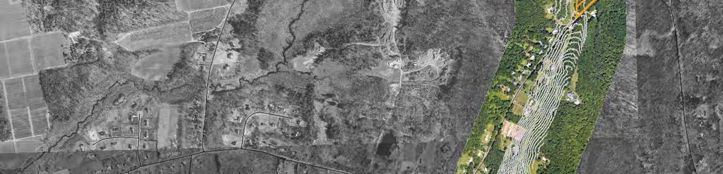
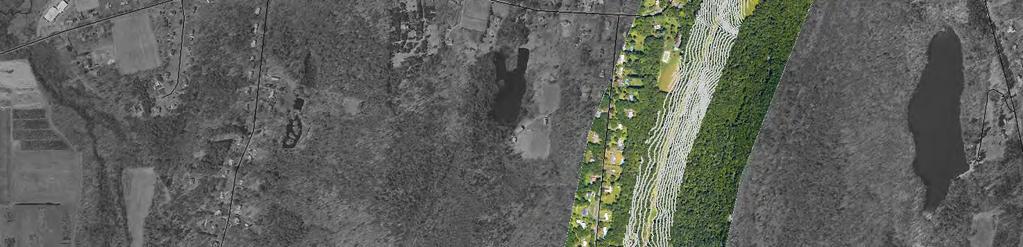
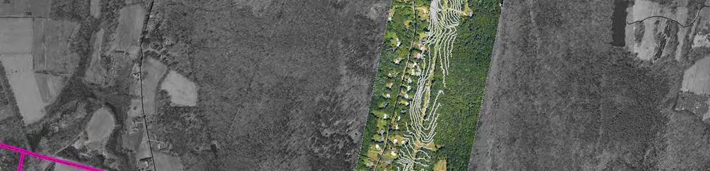
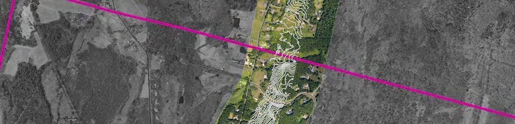
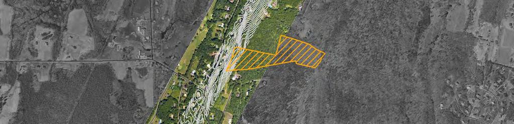
7 Drainage Analysis-Newgate/Phelps & Hatchett Hill Road Areas Rev. 0 Introduction 2.0 INTRODUCTION Based on comments received from residents and town officials through various forums, CL&P initiated this review. Due to a variety of factors some residents along the GSRP ROW have existing drainage/surface water runoff problems on their properties, and are concerned that construction, including the additional tree clearing, will alter/increase the amount and frequency of runoff they currently have. Most of the comments received are from residents along Phelps Road and Newgate Road in East Granby and Suffield. However, one resident on Adams Road in East Granby commented as well. As a result these are the two areas examined and discussed in this report. As designed, the control measures recommended in this report will provide adequate control of surface water flow (sheet and concentrated) across these two areas during construction, and until the areas have been stabilized. Therefore there will be no long-term increase in surface water runoff resulting from the construction in these areas. They will not provide control of ground water within or outside of these areas, nor will they permanently reduce the amount of runoff that ultimately leaves these areas. During the Development and Management (D&M) Plan process, which is mandated by the Connecticut Siting Council (CSC), the location of additional control measures that are needed to protect wetlands and watercourses, prevent sedimentation and erosion issues, and to maintain the stability of all improved surfaces (access roads and crane pads) will be determined. The final D&M Plan, to be submitted to the CSC and each town, will also include all controls identified in this report. All control measures will be inspected regularly and will be repaired, reinforced, and upgraded as needed throughout the Project s duration. Northeast Utilities Transmission Business Unit s Best Management Practices: Construction and Maintenance Environmental Requirements Connecticut (provided under separate cover or as an appendix to the D&M Plan for Construction of the Greater Springfield Reliability Project) will be adhered to when inspecting and maintaining all erosion control measures. 2.1 NEWGATE/PHELPS ROAD AREA The Newgate/Phelps Road area is located within East Granby and Suffield and is generally bounded by Phelps Road on the north, Newgate Road on the west, the western slope of West Suffield Mountain on the east, and the intersection of Copper Hill Road and Newgate Road on the south. Except for residential development to the west of the ROW, and scattered residential development to the east, the area consists of wooded land with varying slopes that are in excess of 30 percent in some areas. This area is shown on Figure 1. Northeast Utilities 2-1 Burns & McDonnell GSRP 345-kV Line D&M Plan Appendix E: Page 6 of 36
8 Apple Ln Copper Hill Rd Old Farms Ln \\Espsrv\data\DATA2\Projects\NUS\SNETR_Projects\45063_Springfield_345kV\Environmental\GIS\ARC\ArcMXD\Network\GreaterSpringfield\Analysis\Sediment_Survey\GSRP_Overview_Phelps_Road.mxd Date: 11/11/09 COPYRIGHT 2007 BURNS & McDONNELL ENGINEERING COMPANY, INC. Phelps Rd Copper Hill Rd Copper Hill Rd Legend Proposed Structures Wetlands Existing Structures NU Owned Property Proposed 345kV Route Centerline Vernal Pool Existing Centerline Contours (5 ft) Parcel Boundary Town Boundary Existing ROW Expanded ROW Source: AECOM, Coler & Colantonio, ESRI and Burns & McDonnell Engineering. Image Source: Optimal Geomatics and CT DOT Griffin Rd Country Club Ln NORTH Woodledge Dr Newgate Rd Wyncairn Newgate/ Phelps Road Locus Map Figure 1 Mountain Rd Ridge Blvd 1, ,500 Feet GSRP 345-kV Line D&M Plan Appendix E: Page 7 of 36
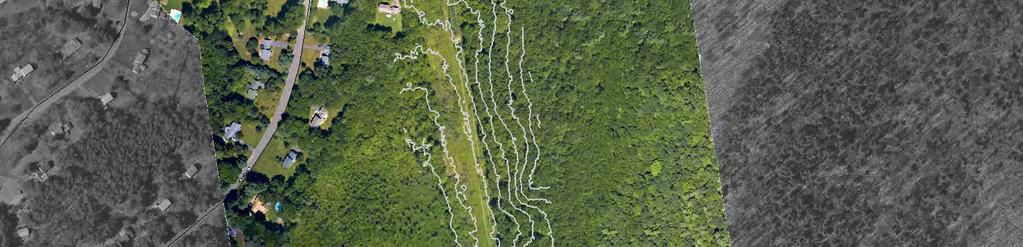
9 Drainage Analysis-Newgate/Phelps & Hatchett Hill Road Areas Rev. 0 Introduction Public Comments Comments from several home owners along Phelps Road and Newgate Road were received. Most comments reflected that some residents in this area have installed engineered drainage systems to control the water that flows down the hill, through the ROW, before reaching their properties at the base of the slope. These systems are currently effective, but the residents are concerned the construction may result in runoff changes that their engineered systems are not designed to handle. Another resident expressed concern about an existing drainage issue between his home and his neighbor s home. During rain events water flows from the ROW behind their homes to Newgate Road where it freezes during the winter, creating a hazardous situation. According to the resident, the Town is aware of this situation. 2.2 HATCHETT HILL ROAD AREA This area is approximately bounded by Holcomb Road on the north, the western slope of Hatchett Hill on the east, Hatchett Hill Road on the south, and the approximate toe of the slope for Hatchett Hill on the west. Adams Road, a cul-de-sac, ends at the west edge of the ROW. Marsh Pond and its associated wetland system are located to the south of Adams Road. This system receives surface and ground water from the south, from residential development to the west and north, and from Hatchett Hill to the east. The west slope of Hatchett Hill is heavily wooded with steep slopes of 10 percent or greater. This area is shown on Figure Public Comments A resident that lives at the end of Adams Road expressed concern that Marsh Pond and its associated forested wetland system south of his property frequently overflows. If the Project causes more water to drain into the pond during construction, it will exacerbate the problem. The resident states his yard, as well as his street, can be a sheet of ice during the winter. He suggested that the Project consider tying into the Town s existing storm drainage system in the street to capture the runoff leaving the ROW, thereby decreasing the amount of additional water that ultimately reaches his property. Northeast Utilities 2-2 Burns & McDonnell GSRP 345-kV Line D&M Plan Appendix E: Page 8 of 36


10 Holcomb St Lexington Dr Adams Dr \\Espsrv\data\DATA2\Projects\NUS\SNETR_Projects\45063_Springfield_345kV\Environmental\GIS\ARC\ArcMXD\Network\GreaterSpringfield\Analysis\Sediment_Survey\GSRP_Overview_Sediment_Maps.mxd Date: 11/11/09 COPYRIGHT 2007 BURNS & McDONNELL ENGINEERING COMPANY, INC. Concord Dr Hatchett Hill Rd Legend Proposed Structures Wetlands Existing Structures NU Owned Property Proposed 345kV Route Centerline Vernal Pool Existing Centerline Contours (5 ft) Parcel Boundary Town Boundary Existing ROW Expanded ROW Source: AECOM, Coler & Colantonio, ESRI and Burns & McDonnell Engineering. Image Source: Optimal Geomatics and CT DOT NORTH Hatchett Hill Ln Hatchett Hill Locus Map Figure Feet GSRP 345-kV Line D&M Plan Appendix E: Page 9 of 36
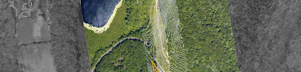
11 Drainage Analysis-Newgate/Phelps & Hatchett Hill Road Areas Rev. 0 Runoff Characteristics & Flow Calculations 3.0 RUNOFF CHARACTERISTICS & FLOW CALCULATIONS To assess current drainage conditions and any adverse impacts the construction may cause, runoff flows for the two, ten, and fifty-year storm events were calculated. The calculations were done per the 2004 Connecticut Stormwater Quality Manual, Chapter 7, the 2003 Connecticut Department of Transportation Drainage Manual, and the 2002 Connecticut Guidelines for Soil Erosion and Sediment Control, and are based on the Rational Method. The Rational Method is a standard equation used, for small drainage areas of up to approximately 200 acres, to calculate and estimate the peak rate of runoff at any location in a watershed. The factors used to calculate this are the size of the drainage area, the runoff coefficient, which is dependent on what type of land use is present (e.g. asphalt parking lot versus green space), and the mean rainfall intensity for the design storm event. The runoff coefficient is an estimate of how much of the rain that hits the ground will run off. It will obviously vary with topography, land use, type and amount of vegetation cover, and moisture content of the soil. For example, a runoff coefficient for asphalt pavement is 0.98, which means 98 percent of the water runs off, whereas green space has a runoff coefficient of 0.30, meaning 30 percent runs off and the remainder soaks in. Runoff coefficients were based on Table 6-3 from the 2003 Connecticut Department of Transportation Drainage Manual. This table includes runoff coefficients for pervious areas based on slope rather than on land use. By looking at aerial photographs and visiting the site it can be seen that the majority of the drainage areas are pervious; therefore, it was determined to be more logical for this particular project to base the coefficient on slope. With this understanding, the pre- and post-project runoff coefficients are expected to be the same because the Project does not have an impact on the overall drainage area slope. The runoff characteristics have been grouped into two flow types, concentrated and sheet flow. Areas of concentrated flows were determined from the USGS maps where an obvious channel or concentration of flow exists. Areas of flow not considered concentrated flow areas were assumed to be sheet flow, which is flow that is not intercepted by the erosion control measures at a specific point. Areas of sheet flow are typically on a hillside prior to the runoff reaching a ditch, swale, or creek. For each area, subbasins were delineated using USGS quad maps (see Figures 3 and 4). Times of concentration were calculated for sheet, shallow concentrated, and open channel flow as required. The time of concentration is equal to the amount of time it takes for runoff to flow from the furthest point in a given watershed to the point of concern. A maximum of 100 linear feet was assumed for the flow length in the sheet flow calculations because the flow path is not always perpendicular to the contour lines. Northeast Utilities 3-1 Burns & McDonnell GSRP 345-kV Line D&M Plan Appendix E: Page 10 of 36

12 LL 1152 LL 1148 LL 1098 LL 1083 Subbasin 10 DA= 78.3ac Subbasin 8 DA= 22.3ac Subbasin 3 DA= 31.2ac Subbasin 1 DA= 50.7ac Subbasin 7 DA= 120.6ac Subbasin 4 DA= 20.3ac Subbasin 2 DA= 128.4ac Hampden M ou n tain ld She Subbasin 12 DA= 36.6ac Subbasin 9 DA= 44.7ac Subbasin 5 DA= 17.0ac Legend Subbasin 168 Hartford Subbasin 11 DA= 35.6ac Subbasin 14 DA= 19.1ac Subbasin 6 DA= 313.1ac Greater Springfield Reliability Project Subbasin Map #2 November 11, 2009 on Hartford Bradley Intl Springfield Center COPYRIGHT 2008 BURNS & McDONNELL ENGINEERING COMPANY, INC. \\kcm-fs-006\data\data2\projects\nus\snetr_projects\45063_springfield_345kv\environmental\gis\arc\arcmxd\network\greaterspringfield\analysis\gsrp_9600_subbasin_9_11_09_map2.mxd Subbasin 13 DA= 21.4ac Source: USGS 1:24,000 Topographic Map, Hartford County, CT (2000); ESRI and Burns & McDonnell Engineering Feet Figure 3 GSRP 345-kV Line D&M Plan Appendix E: Page 11 of 36
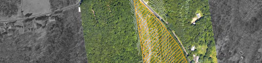
13 Sub-basin 3 DA= 13.7ac Sub-basin 2 DA= 67.4ac Sub-basin 1 DA= 64.9ac Hampden M ou n tain Hartford 20 Legend Subbasin ld She Greater Springfield Reliability Project Subbasin Map #1 November 11, 2009 on Hartford Bradley Intl Springfield Center COPYRIGHT 2008 BURNS & McDONNELL ENGINEERING COMPANY, INC. \\kcm-fs-006\data\data2\projects\nus\snetr_projects\45063_springfield_345kv\environmental\gis\arc\arcmxd\network\greaterspringfield\analysis\gsrp_9600_subbasin_9_11_09_map1.mxd LL 1034 Source: USGS 1:24,000 Topographic Map, Hartford County, CT (2000); ESRI and Burns & McDonnell Engineering. GSRP 345-kV Line D&M Plan Appendix E: Page 12 of Feet Figure 4
14 Drainage Analysis-Newgate/Phelps & Hatchett Hill Road Areas Rev. 0 Runoff Characteristics & Flow Calculations 3.1 TWO-, TEN-, AND FIFTY-YEAR STORM EVENT CALCULATIONS If construction activities occurred for less than a one-year period in each particular subbasin, the Best Management Practices (BMPs) would be considered temporary based on the 2002 Connecticut Guidelines for Soil Erosion and Sediment Control Manual. If the BMPs are assumed to be temporary, the two-year storm is generally used to design the necessary erosion controls, and are then assumed to need maintenance after larger storm events. However, although the BMPs will only be temporary, they will be in place for slightly longer than one year. Therefore, calculations for the ten- and fifty-year storm events were also provided. The associated flows (Total Q) in each sub-basin were calculated based on the time of concentration calculations and average rainfall intensities. The rainfall intensity is the average rainfall rate for a specific duration and a selected frequency. The duration is assumed to be equal to the time of concentration. The flows and associated runoff velocities for both areas are summarized in the subsequent tables Newgate/Phelps Road Area The Newgate/Phelps Road Area has 14 sub-basins (see Figure 3, Subbasin Map #2). The following tables provide a summary of the calculations for a two-, ten-, and fifty-year storm event. Table 3-1 Two-Year Storm Event Subbasin Drainage Area (acres) 2-Year Rainfall Intensity (in./hr.) Pre & Post Construction Runoff Coefficient 2-Year Total Q Subbasin (cu. ft./sec.) 2-Year Single Point Q (cu. ft./sec.) Linear Feet 2-Year Total Q Per Foot (cu. ft./sec.) 2-Year Single Point Velocity (ft./sec.) Northeast Utilities 3-2 Burns & McDonnell GSRP 345-kV Line D&M Plan Appendix E: Page 13 of 36
15 Drainage Analysis-Newgate/Phelps & Hatchett Hill Road Areas Rev. 0 Runoff Characteristics & Flow Calculations Table 3-2 Ten-Year Storm Event Subbasin Drainage Area (acres) 10-Year Rainfall Intensity (in./hr.) Pre & Post Construction Runoff Coefficient 10-Year Total Q Subbasin (cu. ft./sec.) 10-Year Single Point Q (cu. ft./sec.) Linear Feet 10-Year Total Q Per Foot (cu. ft./sec.) 10-Year Single Point Velocity (ft./sec.) Table 3-3 Fifty-Year Storm Event Subbasin Drainage Area (acres) 50-Year Rainfall Intensity (in./hr) Pre & Post Construction Runoff Coefficient 50-Year Total Q Subbasin (cu. ft./sec.) 50-Year Single Point) Q (cu. ft./sec.) Linear Feet 50-Year Total Q Per Foot (cu. ft./sec.) 50-Year Single Point Velocity (ft./sec.) Northeast Utilities 3-3 Burns & McDonnell GSRP 345-kV Line D&M Plan Appendix E: Page 14 of 36
16 Drainage Analysis-Newgate/Phelps & Hatchett Hill Road Areas Rev. 0 Runoff Characteristics & Flow Calculations As shown in the previous tables, the calculated Single Point Velocities are generally less than 3.5 feet per second for the two- and ten-year storm events in this area. This velocity is less than the erosive velocity of the existing soil types, which is 5 feet per second. Therefore, the 2- and 10- year storm events should pose no erosive threat. The stone check dam control structures shown on the Site Drawings in Appendix A are designed to withstand the expected concentrated flow for two- and ten-year storm events in this area. The fifty-year storm velocities, however, are 4 to 5 feet per second. Fifty-year storms have more potential to exhibit an erosive behavior, and therefore would likely require the heights and widths of the stone check dam controls shown on the Site Drawings to be increased to handle the peak flows without failure or adverse tail water effects. For the areas where sheet flow occurs (all areas not defined as concentrated flow path), it is recommended that silt fence be installed on the downhill side of the disturbed area. The Total Q Per Foot for the two- and ten-year storm events are the same in this area. For a fifty-year storm event the total Q does increase slightly, but would have no effect on the location or type of silt fence used to control erosion in these areas. Therefore, as designed, the silt fence control structures shown on the Site Drawings will withstand the expected sheet flow for the two-, ten- and fifty-year storm events in this area Hatchett Hill Road Area The Hatchett Hill Road Area has three subbasins (see Figure 4, Subbasin Map #1). The following tables provide a summary of the calculations for the two-, ten-, and fifty-year storm event. Table 3-4 Two-Year Storm Event Subbasin Drainage Area (acres) 2-Year Rainfall Intensity (in./hr.) Pre & Post Construction Runoff Coefficient 2-Year Total Q Subbasin (cu. ft/sec.) Linear Feet 2-Year Total Q Per Foot (cu. ft./sec.) Northeast Utilities 3-4 Burns & McDonnell GSRP 345-kV Line D&M Plan Appendix E: Page 15 of 36
17 Drainage Analysis-Newgate/Phelps & Hatchett Hill Road Areas Rev. 0 Runoff Characteristics & Flow Calculations Table 3-5 Ten-Year Storm Event Sub-basin Drainage Area (acres) 10-Year Rainfall Intensity (in./hr.) Pre & Post Construction Runoff Coefficient 10-Year Total Q Sub-basin (cu. ft/sec.) Linear Feet 10-Year Total Q Per Foot (cu. ft/sec.) Table 3-6 Fifty-Year Storm Event Sub-basin Drainage Area (acres) 50-Year Rainfall Intensity (in./hr.) Pre & Post Construction Runoff Coefficient 50-Year Total Q Sub-basin (cu. ft./sec.) Linear Feet 50-Year Total Q Per Foot (cu. ft./sec.) There were no single point sources identified in any of the subbasins in this area. For the areas where sheet flow occurs down the slope of an embankment (all areas not defined as concentrated flow path), it is recommended that silt fence be installed on the downhill side of the disturbed area. The Total Q per foot for the two- and ten-year storm events are the same in this area. For a fifty-year storm event the total Q does increase slightly, but it would not affect the location or type of silt fence used to control erosion in these areas. Therefore, as designed, the silt fence control structures shown on the Site Drawings will withstand the expected sheet flow for two-, ten- and fifty-year storm events in this area. Northeast Utilities 3-5 Burns & McDonnell GSRP 345-kV Line D&M Plan Appendix E: Page 16 of 36
ATTACHMENT D SNOW REMOVAL AND DE-ICING PROCEDURES
 Interstate Reliability Project 345-kV Transmission Lines Development & Management Plan Volume 2 ATTACHMENT D SNOW REMOVAL AND DE-ICING PROCEDURES INTERSTATE RELIABILITY PROJECT The Interstate Reliability
STREUVER FIDELCO CAPPELLI, LLC YONKERS DOWNTOWN DEVELOPMENT PHASE 1. DRAFT ENVIRONMENTAL IMPACT STATEMENT For: PALISADES POINT
 STREUVER FIDELCO CAPPELLI, LLC YONKERS DOWNTOWN DEVELOPMENT PHASE 1 DRAFT ENVIRONMENTAL IMPACT STATEMENT For: PALISADES POINT Prepared by: PAULUS, SOKOLOWSKI & SARTOR STORMWATER MANAGEMENT 1. Methodology
Woodford County Erosion Prevention Plan and Permit. Application #
 Woodford County Erosion Prevention Plan and Permit Application # Date Instructions: Applicant will complete Parts A and B, and attach a proposed site diagram. This diagram must be completed in accordance
INFLOW DESIGN FLOOD CONTROL SYSTEM PLAN 40 C.F.R. PART PLANT YATES ASH POND 2 (AP-2) GEORGIA POWER COMPANY
 GEORGIA POWER COMPANY") INFLOW DESIGN FLOOD CONTROL SYSTEM PLAN 40 C.F.R. PART 257.82 PLANT YATES ASH POND 2 (AP-2) GEORGIA POWER COMPANY EPA s Disposal of Coal Combustion Residuals from Electric Utilities Final Rule (40 C.F.R.
INFLOW DESIGN FLOOD CONTROL SYSTEM PLAN 40 C.F.R. PART 257.82 PLANT YATES ASH POND 2 (AP-2) GEORGIA POWER COMPANY EPA s Disposal of Coal Combustion Residuals from Electric Utilities Final Rule (40 C.F.R.
Hydrology Study Report
 Hafeez Consulting www.hafeezconsulting.com Civil/ Structural Engineering, Design & Construction 1451 S. Hacienda St. Anaheim CA 92804 (714) 225-4565 Fax (714)917-2977 engineer@hafeezconsulting.com Hydrology
Sediment Trap. A temporary runoff containment area, which promotes sedimentation prior to discharge of the runoff through a stabilized spillway.
 Sediment Trap SC-15 Source: Caltrans Construction Site Best Management Practices Manual, 2003. Description A temporary runoff containment area, which promotes sedimentation prior to discharge of the runoff
Local Flood Hazards. Click here for Real-time River Information
 Local Flood Hazards Floods of the White River and Killbuck Creek are caused by runoff from general, and/or intense rainfall. Other areas of flooding concern are from the Boland Ditch and Pittsford Ditch.
Drainage Analysis. Appendix F
 Drainage Analysis Appendix F Golden View Drive Elizabeth Street LMORE CREEK Ricky Road Rabbit Creek Road LITTLE RABBIT CREEK East 156th Avenue MOA Project #10-026 Golden View Drive Intersection
Map Reading 101: Using and Reading Maps and Plans
 Map Reading 101: Using and Reading Maps and Plans A Key Skill for Land Use Commissioners Paula Stahl, LLA, ASLA, AICP Land Use Educator Green Valley Institute Land Use Academy 1 How most of us react to
Materials. Use materials meeting the following.
 208.01 Section 208. SOIL EROSION AND SEDIMENTATION CONTROL 208.01 Description. Install and maintain erosion and sedimentation controls to minimize soil erosion and to control sedimentation from affecting
Module 5: Channel and Slope Protection Example Assignments
 Module 5: Channel and Slope Protection Example Assignments A) Example Project Assignment on Slope and Swale Design North America Green Software Example (Erosion Control Materials Design Software) The following
Template for Sediment and Erosion Control Plan General Instructions. Section Instructions
 Template for Sediment and Erosion Control Plan General Instructions Introduction: Soil erosion and sediment deposition from farmlands can contribute to degraded surface water quality. Sediment delivery
FOR PROJECTS INITIATED AFTER NOVEMBER 1, 2008 ITEM 716 EMBANKMENT EARTH OUTLET SEDIMENT TRAP
 AFTER NOVEMBER 1, 2008 ITEM 716 EMBANKMENT EARTH OUTLET SEDIMENT TRAP 716.1 Description. This work shall consist of furnishing, installing, maintaining, and removing temporary erosion protection and sediment
Suitable Applications Sediment traps should be considered for use:
 Categories EC Erosion Control SE Sediment Control TC Tracking Control WE Wind Erosion Control Non-Stormwater NS Management Control Waste Management and WM Materials Pollution Control Legend: Primary Objective
Appendix E Guidance for Shallow Flooding Analyses and Mapping
 Appendix E Guidance for Shallow Flooding Analyses and Mapping E.1 Introduction Different types of shallow flooding commonly occur throughout the United States. Types of flows that result in shallow flooding
Sediment Control Log (SCL)
") Description A sediment control log is a linear roll made of natural materials such as straw, coconut fiber, or other fibrous material trenched into the ground and held with a wooden stake. Sediment control
Description A sediment control log is a linear roll made of natural materials such as straw, coconut fiber, or other fibrous material trenched into the ground and held with a wooden stake. Sediment control
LOCATED IN INDIAN RIVER COUNTY PREPARED FOR S.J.R.W.M.D. AND F.W.C.D. DECEMBER, 2003 Updated 2007 Updated May 2014 PREPARED BY
 FELLSMERE WATER CONTROL DISTRICT EAST MASTER DRAINAGE PLAN AND STORMWATER HYDROLOGIC ANALYSIS OF THE GRAVITY DRAINAGE SYSTEM LOCATED BETWEEN THE EAST BOUNDARY, LATERAL U, THE MAIN CANAL, AND DITCH 24 LOCATED
Continuing Education Associated with Maintaining CPESC and CESSWI Certification
 Continuing Education Associated with Maintaining CPESC and CESSWI Certification Module 2: Stormwater Management Principles for Earth Disturbing Activities Sponsors: ODOTs Local Technical Assistance Program
Sediment Trap. At multiple locations within the project site where sediment control is needed.
 Sediment Trap SE-3 Objectives EC Erosion Control SE Sediment Control TR Tracking Control WE Wind Erosion Control Non-Stormwater NS Management Control Waste Management and WM Materials Pollution Control
Stormwater Guidelines and Case Studies. CAHILL ASSOCIATES Environmental Consultants West Chester, PA (610)
") Stormwater Guidelines and Case Studies CAHILL ASSOCIATES Environmental Consultants West Chester, PA (610) 696-4150 www.thcahill.com Goals and Challenges for Manual State Stormwater Policy More Widespread
Stormwater Guidelines and Case Studies CAHILL ASSOCIATES Environmental Consultants West Chester, PA (610) 696-4150 www.thcahill.com Goals and Challenges for Manual State Stormwater Policy More Widespread
CITY OF CAPE CORAL STORMWATER MASTER PLAN PHASE II - PART 1 BASINS 4, 10, & 14 SUB-BASIN DRAINAGE IMPROVEMENTS HYDRAULIC ANALYSIS SUMMARY
 CITY OF CAPE CORAL STORMWATER MASTER PLAN PHASE II - PART 1 BASINS 4, 10, & 14 SUB-BASIN DRAINAGE IMPROVEMENTS HYDRAULIC ANALYSIS SUMMARY Cape Coral, FL Prepared for: The City of Cape Coral Public Works
STORMWATER MANAGEMENT COMPUTATIONS. Mount Prospect
 STORMWATER MANAGEMENT COMPUTATIONS Mount Prospect MHG PROJECT No. 2011.173.11 November 6, 2014 Prepared for: Piney Meetinghouse Investments c/o Mr. Dennis Fling 14801 Clopper Road Boyds, MD 20841 (301)
HISTORY OF CONSTRUCTION FOR EXISTING CCR SURFACE IMPOUNDMENT PLANT GASTON ASH POND 40 CFR (c)(1)(i) (xii)
(1)(i) (xii)") HISTORY OF CONSTRUCTION FOR EXISTING CCR SURFACE IMPOUNDMENT PLANT GASTON ASH POND 40 CFR 257.73(c)(1)(i) (xii) (i) Site Name and Ownership Information: Site Name: E.C. Gaston Steam Plant Site Location:
HISTORY OF CONSTRUCTION FOR EXISTING CCR SURFACE IMPOUNDMENT PLANT GASTON ASH POND 40 CFR 257.73(c)(1)(i) (xii) (i) Site Name and Ownership Information: Site Name: E.C. Gaston Steam Plant Site Location:
Black Gore Creek 2013 Sediment Source Monitoring and TMDL Sediment Budget
 Black Gore Creek 2013 Sediment Source Monitoring and TMDL Sediment Budget Prepared for: Prepared By: - I. Introduction The Black Gore Creek Total Maximum Daily Load (TMDL) was developed in collaboration
Objectives: After completing this assignment, you should be able to:
 Data Analysis Assignment #1 Evaluating the effects of watershed land use on storm runoff Assignment due: 21 February 2013, 5 pm Objectives: After completing this assignment, you should be able to: 1) Calculate
Section 4: Model Development and Application
 Section 4: Model Development and Application The hydrologic model for the Wissahickon Act 167 study was built using GIS layers of land use, hydrologic soil groups, terrain and orthophotography. Within
Standards for Soil Erosion and Sediment Control in New Jersey May 2012
 STANDARD FOR SEDIMENT BASIN Definition A barrier, dam, excavated pit, or dugout constructed across a waterway or at other suitable locations to intercept and retain sediment. Basins created by construction
Chapter 10 - Sacramento Method Examples
 Chapter 10 Sacramento Method Examples Introduction Overview This chapter presents two example problems to demonstrate the use of the Sacramento method. These example problems use the SACPRE and HEC-1 computer
This site will utilize an infiltration berm to manage the two-year/24-hour volume increase.
 Gates TETRA TECH, INC. By: RH Date: 1/30/2017 Subject: Gates Road Checked By: JB Date: 2/1/2017 PCSM Design and Evaluation PURPOSE: The purpose of these calculations is to design a Post-Construction Stormwater
Template for Sediment and Erosion Control Plan General Instructions
 Template for Sediment and Erosion Control Plan General Instructions Introduction: Soil erosion and sediment deposition from farmlands can contribute to degraded surface water quality. Sediment delivery
MIDDLESEX COUNTY Department of Planning and Community Development P.O. Box 427, Saluda, VA Phone: Fax:
 MIDDLESEX COUNTY Department of Planning and Community Development P.O. Box 427, Saluda, VA 23149 Phone: 804-758-3382 Fax: 804-758-0061 LAND DISTURBANCE PERMIT SUBMISSION REQUIREMENTS In order to expedite
2267 N o r t h 1500 W C l i n t o n U T 84015
 P l a n n i n g C o m m i s s i o n M e m b e r s C h a i r J a c o b B r i g g s V i c e C h a i r G a r y T y l e r T o n y T h o m p s o n J o l e n e C r e s s a l l A n d y H a l e D e r e c k B a
This site will utilize an infiltration berm to manage the two-year/24-hour volume increase.
 Gates TETRA TECH, INC. By: RH Date: 11/11/2016 Subject: Gates Road Checked By: JB Date: 11/13/2016 PCSM Design and Evaluation PURPOSE: The purpose of these calculations is to design a Post-Construction
1.0 INSPECTION ANNUAL INSPECTION, JUNE 29, 2011 CARMACKS COPPER PROJECT, CARMACKS, YUKON. Dear Mr. West-Sells,
 Doc. No. 162 Rev. 0 Mr. Paul West-Sells President & Chief Operating Officer Western Copper Corporation 2060-1111 West Georgia Street Vancouver, BC V6E 4M3 ANNUAL INSPECTION, JUNE 29, 2011 CARMACKS COPPER
Emergency Action Plan (EAP) Tata Pond Dam
 Tata Pond Dam") For Official Use Only Not for Public Distribution 02/03/16 Emergency Action Plan (EAP) Tata Pond Dam State of Connecticut Dam ID: 0000 Town or City, County, Connecticut Name of Dam Owner Dam Hazard Classification
For Official Use Only Not for Public Distribution 02/03/16 Emergency Action Plan (EAP) Tata Pond Dam State of Connecticut Dam ID: 0000 Town or City, County, Connecticut Name of Dam Owner Dam Hazard Classification
Specifications Whitcomb Elementary School Demolition January 15, 2016
 SECTION 31 2500 - EROSION CONTROL PART 1 - GENERAL 1.1 RELATED DOCUMENTS: A. The provisions of the Contract Documents apply to the work of this Section. B. The Virginia Erosion and Sediment Control Handbook,
B805 TEMPORARY EROSION AND SEDIMENT CONTROL MEASURES - OPSS 805
 B805 MEASURES - OPSS 805 805.1 GENERAL Construction activities frequently remove protective cover and expose soil to accelerated rates of erosion. Sediments generated thereby can be conveyed via runoff
COMMUNITY EMERGENCY RESPONSE TEAM FLOODS INTRODUCTION
 INTRODUCTION Floods are one of the most common hazards in the United States. A flood occurs any time a body of water rises to cover what is usually dry land. Flood effects can be local, impacting a neighborhood
Chapter 5 CALIBRATION AND VERIFICATION
 Chapter 5 CALIBRATION AND VERIFICATION This chapter contains the calibration procedure and data used for the LSC existing conditions model. The goal of the calibration effort was to develop a hydraulic
ARTICLE 5 (PART 2) DETENTION VOLUME EXAMPLE PROBLEMS
 DETENTION VOLUME EXAMPLE PROBLEMS") ARTICLE 5 (PART 2) DETENTION VOLUME EXAMPLE PROBLEMS Example 5.7 Simple (Detention Nomograph) Example 5.8 Offsite and Unrestricted Areas (HEC-HMS) Example 5.9 Ponds in Series w/ Tailwater (HEC-HMS) Example
ARTICLE 5 (PART 2) DETENTION VOLUME EXAMPLE PROBLEMS Example 5.7 Simple (Detention Nomograph) Example 5.8 Offsite and Unrestricted Areas (HEC-HMS) Example 5.9 Ponds in Series w/ Tailwater (HEC-HMS) Example
**Temporary Erosion Control**
 Construction operations And methods **Temporary Erosion Control** The test will more than likely just have a basic word problem dealing with Erosion control, if it has anything on the test. So just review,
PENNSYLVANIA DEPARTMENT OF TRANSPORTATION ENGINEERING DISTRICT 3-0
 PENNSYLVANIA DEPARTMENT OF TRANSPORTATION ENGINEERING DISTRICT 3-0 LYCOMING COUNTY S.R.15, SECTION C41 FINAL HYDROLOGIC AND HYDRAULIC REPORT STEAM VALLEY RUN STREAM RELOCATION DATE: June, 2006 REVISED:
APPENDIX E. GEOMORPHOLOGICAL MONTORING REPORT Prepared by Steve Vrooman, Keystone Restoration Ecology September 2013
 APPENDIX E GEOMORPHOLOGICAL MONTORING REPORT Prepared by Steve Vrooman, Keystone Restoration Ecology September 2 Introduction Keystone Restoration Ecology (KRE) conducted geomorphological monitoring in
TPDES: Soil, Erosion and Sedimentation Methods
 SAWS TPDES: Soil, Erosion and Sedimentation Methods Philip Handley Supervisor-Resource Protection & Compliance August 25, 2014 TPDES: Soil, Erosion and Sedimentation Methods Soil Common term: Dirt Common
APPENDIX B DESIGN CRITERIA FOR TEMPORARY WATER QUALITY BMPS USED DURING CONSTRUCTION
 APPENDIX B DESIGN CRITERIA FOR TEMPORARY WATER QUALITY BMPS USED DURING CONSTRUCTION This Appendix presents design criteria and example calculations for the following temporary water quality BMPs for use
Chapter 7 Mudflow Analysis
 Chapter 7 Mudflow Analysis 7.0 Introduction This chapter provides information on the potential and magnitude of mud floods and mudflows that may develop in Aspen due to rainfall events, snowmelt, or rain
CONSTRUCTION EXIT SEDIMENT BARRIER
 241428_itizen ield Guide_v3 2/22/06 11:09 M Page 1 (1,1) ONSTRUTION EXIT stone pad located where traffic leaves a construction site to eliminate the transport of soil to public streets. SEDIMENT BRRIER
CCR Rule Annual Inspection Report (cont.) 2
 2") The inspection findings consisted of maintenance items and items that were not observed to be signs or potential signs of significant structural weakness. No deficiencies or disrupting conditions that
The inspection findings consisted of maintenance items and items that were not observed to be signs or potential signs of significant structural weakness. No deficiencies or disrupting conditions that
Sediment Control Practices. John Mathews Ohio Dept. of Natural Resources, Division of Soil and Water Resources
 Sediment Control Practices John Mathews Ohio Dept. of Natural Resources, Division of Soil and Water Resources Practices Treat the Largest Soil Particles Sand Sand Silt Clay Treated Untreated Settleable
This site will utilize an infiltration berm to manage the two-year/24-hour volume increase.
 High Street TETRA TECH, INC. By: RH Date: 1/30/2017 Subject: High Street Checked By: JB Date: 2/1/2017 PCSM Design and Evaluation PURPOSE: The purpose of these calculations is to design a Post-Construction
Chapter 7 Mudflow Analysis
 Chapter 7 Mudflow Analysis 7.0 Introduction This chapter provides information on the potential and magnitude of mud floods and mudflows that may develop in Aspen due to rainfall events, snowmelt, or rain
STORMWATER REPORT FRITO LAY SUBDIVISION NO. 3
 STORMWATER REPORT FRITO LAY SUBDIVISION NO. 3 May 2018 STORMWATER REPORT I. Subdivision Data a. The parcel is adjacent to the existing Frito Lay property in Topeka; and the subject plat application encompasses
Selected Site BMPs: Why s the Water Muddy? John C. Hayes, Ph.D., P. E. Biosystems Engineering Clemson University
 Selected Site BMPs: Why s the Water Muddy? John C. Hayes, Ph.D., P. E. Biosystems Engineering Clemson University The BMP worked fine until last week when it rained! Turbidity Best Management Practices
North Carolina Simplified Inundation Maps For Emergency Action Plans December 2010; revised September 2014; revised April 2015
 North Carolina Simplified Inundation Maps For Emergency Action Plans December 2010; revised September 2014; revised April 2015 INTRODUCTION Emergency Action Plans (EAPs) are critical to reducing the risks
Erosion and Sediment Control Measures 2.7 Silt Fences
 Erosion and Sediment Control Measures Silt fences are designed to intercept sheet flow sediment laden stormwater run-off and filter out both the larger and smaller particles of sediment. Silt fences and
Orica Australia Pty Ltd Ammonium Nitrate Facility Upgrade
 Orica Australia Pty Ltd Ammonium Nitrate Facility Upgrade January 2010 Revision 0 Contents 1. Introduction 1 1.1 Purpose 1 1.2 Objectives 1 1.3 Relevant Environmental Legislation, Guidelines and Policies
TREASURE COAST REGIONAL PLANNING COUNCIL M E M O R A N D U M. To: Council Members AGENDA ITEM 4B10
 TREASURE COAST REGIONAL PLANNING COUNCIL M E M O R A N D U M To: Council Members AGENDA ITEM 4B10 From: Date: Subject: Staff December 14, 2018 Council Meeting Local Government Comprehensive Plan Review
BRANDON LAKES AVENUE PRE AND POST CONDITIONS DRAINAGE REPORT
 BRANDON LAKES AVENUE PRE AND POST CONDITIONS DRAINAGE REPORT Hillsborough County Public Works County Center, 22nd Floor 601 E. Kennedy Blvd. Tampa, FL 33602 BRANDON LAKES AVENUE DRAINAGE IMPROVEMENTS Capital
Huron Creek Watershed 2005 Land Use Map
 Huron Creek Watershed 2005 Land Use Map Created By: Linda Kersten, 12/20/06 Created For: MTU Introduction to GIS Class (FW 5550) The Huron Creek Watershed Advisory Committee Michigan Technological University,
STORMWATER MANAGEMENT REPORT
 STORMWATER MANAGEMENT REPORT THE FAIRWAYS AT EDGEWOOD LOTS 5 & 6, BLOCK 1201 TOWNSHIP OF RIVER VALE BERGEN COUNTY, NEW JERSEY PREPARED BY: DAPHNE A. GALVIN PROFESSIONAL ENGINEER LICENSE NO. 24GE03434900
APPENDIX B WORKSHEETS & EXHIBITS
 APPENDIX B WORKSHEETS & EXHIBITS A worksheet provides the designer a representation of a measure that allows for input of specific design criteria. The plan designer will be required to assess field conditions
Waterbury Dam Disturbance Mike Fitzgerald Devin Rowland
 Waterbury Dam Disturbance Mike Fitzgerald Devin Rowland Abstract The Waterbury Dam was completed in October 1938 as a method of flood control in the Winooski Valley. The construction began in April1935
August 10, 2007 File:
 August 10, 2007 File: 15-85-72 Alberta Infrastructure and Transportation Room 301, Provincial Building 9621-96 Avenue Peace River, AB T8S 1T4 Attention: Mr. Ed Szmata PEACE REGION (PEACE HIGH LEVEL AREA)
APPENDIX A: EROSION & SEDIMENT CONTROL FORMS
 APPENDIX A: EROSION & SEDIMENT CONTROL FORMS Croy Engineering # 1580.08 EROSION & SEDIMENT CONTROL FORMS Appendix-1 This page intentionally left blank. Croy Engineering # 1580.08 EROSION & SEDIMENT CONTROL
Stone Outlet Sediment Trap
 3.12 Sediment Control Description: A stone outlet sediment trap is a small detention area formed by placing a stone embankment with an integral stone filter outlet across a drainage swale for the purpose
CHAPTER GEOLOGICALLY HAZARDOUS AREAS Applicability Regulations.
 CHAPTER 19.07 GEOLOGICALLY HAZARDOUS AREAS 19.07.010 Applicability. Geologically hazardous areas may pose a threat to the health and safety of citizens when incompatible development is sited in areas of
SAN JACINTO RIVER / BAUTISTA CREEK LEVEE SYSTEM RIVERSIDE COUNTY, CALIFORNIA NLD ID #
 SAN JACINTO RIVER / BAUTISTA CREEK LEVEE SYSTEM RIVERSIDE COUNTY, CALIFORNIA NLD ID # 3805010019 PERIODIC INSPECTION REPORT NO 1 GENERALIZED EXECUTIVE SUMMARY FEBRUARY 2013 FINAL RATING: MINIMALLY ACCEPTABLE
Watershed Analysis Using Remote Sensing and GPS
 25 th Annual Louisiana Remote Sensing and GIS Workshop Baton Rouge, 2009 Watershed Analysis Using Remote Sensing and GPS Warren L. Kron, Jr. Quang Tran Baton Rouge City-Parish Planning Commission José
Technical Memorandum. City of Salem, Stormwater Management Design Standards. Project No:
 Technical Memorandum 6500 SW Macadam Avenue, Suite 200 Portland, Oregon, 97239 Tel: 503-244-7005 Fax: 503-244-9095 Prepared for: Project Title: City of Salem, Oregon City of Salem, Stormwater Management
Flash flood disaster in Bayangol district, Ulaanbaatar
 Flash flood disaster in Bayangol district, Ulaanbaatar Advanced Training Workshop on Reservoir Sedimentation Management 10-16 October 2007. IRTCES, Beijing China Janchivdorj.L, Institute of Geoecology,MAS
Rock & Aggregate Drop Inlet Protection
 Rock & Aggregate Drop Inlet Protection SEDIMENT CONTROL TECHNIQUE Type 1 System Sheet Flow Sandy Soils Type 2 System [1] Concentrated Flow Clayey Soils Type 3 System Supplementary Trap Dispersive Soils
Highland Lake Bathymetric Survey
 Highland Lake Bathymetric Survey Final Report, Prepared For: The Town of Highland Lake 612 Lakeshore Drive Oneonta, AL 35121 Prepared By: Tetra Tech 2110 Powers Ferry Road SE Suite 202 Atlanta, GA 30339
TABLE OF CONTENTS LIST OF TABLES. Page
 TABLE OF CONTENTS Page 11.0 EFFECTS OF THE ENVIRONMENT ON THE PROJECT... 11-1 11.1 Weather Conditions... 11-1 11.2 Flooding... 11-2 11.3 Forest Fires... 11-2 11.4 Permafrost and Subsidence Risk... 11-3
Big Rivers Electric Corporation Disposal of Coal Combustion Residuals (CCR) from Electric Utilities Final Rule CCR Impoundment Liner Assessment Report
 from Electric Utilities Final Rule CCR Impoundment Liner Assessment Report") Big Rivers Electric Corporation Disposal of Coal Combustion Residuals (CCR) from Electric Utilities Final Rule CCR Impoundment Liner Assessment Report CCR Surface Impoundment Information Name: Operator:
Big Rivers Electric Corporation Disposal of Coal Combustion Residuals (CCR) from Electric Utilities Final Rule CCR Impoundment Liner Assessment Report CCR Surface Impoundment Information Name: Operator:
Guide to the use of the Erosion and Sediment Control Evaluation Tool
 Guide to the use of the Erosion and Sediment Control Evaluation Tool December 2017 If you require content in an alternate format please contact us at 905-895-1281 or by email at Accessibility@LSRCA.on.ca
Quick Response Report #126 Hurricane Floyd Flood Mapping Integrating Landsat 7 TM Satellite Imagery and DEM Data
 Quick Response Report #126 Hurricane Floyd Flood Mapping Integrating Landsat 7 TM Satellite Imagery and DEM Data Jeffrey D. Colby Yong Wang Karen Mulcahy Department of Geography East Carolina University
Eagle Creek Post Fire Erosion Hazard Analysis Using the WEPP Model. John Rogers & Lauren McKinney
 Eagle Creek Post Fire Erosion Hazard Analysis Using the WEPP Model John Rogers & Lauren McKinney Columbia River Gorge at Risk: Using LiDAR and GIS-based predictive modeling for regional-scale erosion susceptibility
SAN FRANCISCO DISTRICT INFORMATION REQUESTED FOR VERIFICATION OF CORPS JURISDICTION
 DEPARTMENT OF THE ARMY SAN FRANCISCO DISTRICT, U.S. ARMY CORPS OF ENGINEERS 1455 MARKET STREET SAN FRANCISCO, CALIFORNIA 94103-1398 SAN FRANCISCO DISTRICT INFORMATION REQUESTED FOR VERIFICATION OF CORPS
Stormwater Capacity Analysis for Westover Branch Watershed
 Stormwater Capacity Analysis for Westover Branch Watershed Pimmit Run Little Pimmit Run, Mainstem Stohman's Run Gulf Branch Pimmit Run Tributary Little Pimmit Run, W. Branch Little Pimmit Run, E. Branch
SITE SUMMARY REPORT Candor Dump NONCD Montgomery County
 SITE SUMMARY REPORT Candor Dump NONCD 0000433 Montgomery County Senate Bill 1492 State of North Carolina State Contract N06009S Schnabel Project No. 06210002.23 February 23, 2010 Prepared for: North Carolina
Instream Sediment Control Systems
 Instream Sediment Control Systems INSTREAM PRACTICES Photo 1 Photo 2 Modular sediment The information contained within this series of fact sheets deals only with the design of temporary instream sediment
Using Map and Compass Together
 Using Map and Compass Together In situations where you foresee a potential evacuation on foot, where there are no roads, and no indication as to the direction of travel (i.e., road signs), it is recommended
Agenda. INDOT Office of Environmental Services. Describe Results of FHWA QAR. Landscape and Waterway Permitting Unit. Interviews Site Inspections
 Nathan Saxe Administrator, Ecology and Waterway Permitting Section Back to Basics: Erosion and Sediment Control FHWA INDOT Quality Assurance Review (QAR) Results 1 Agenda INDOT Office of Environmental
SILT FENCE EFFECTIVENESS
 SILT FENCE EFFECTIVENESS Michelle G. Holloway, Department of Earth Sciences, University of South Alabama, Mobile, AL 36688. E-mail: MLG@jaguar1.usouthal.edu. Sediment is the number one pollutant in Dog
Chapter 6 Mapping and Online Tools
 Chapter 6 Mapping and Online Tools The stream site you monitor is just part of a much larger system. When analyzing stream health, it is important to take a holistic view by considering the entire watershed.
APPENDIX F PRE-COURSE WORK
 APPENDIX F PRE-COURSE WORK F-1 Pre-Course Work F-2 Pre-Course Work Intermediate Wildland Fire Behavior, S-290 Pre-Course Work The pre-course work is designed to ensure that students come to class with
The last three sections of the main body of this report consist of:
 Threatened and Endangered Species Geological Hazards Floodplains Cultural Resources Hazardous Materials A Cost Analysis section that provides comparative conceptual-level costs follows the Environmental
Which map shows the stream drainage pattern that most likely formed on the surface of this volcano? A) B)
 B)") 1. When snow cover on the land melts, the water will most likely become surface runoff if the land surface is A) frozen B) porous C) grass covered D) unconsolidated gravel Base your answers to questions
1. When snow cover on the land melts, the water will most likely become surface runoff if the land surface is A) frozen B) porous C) grass covered D) unconsolidated gravel Base your answers to questions
HISTORY OF CONSTRUCTION FOR EXISTING CCR SURFACE IMPOUNDMENT PLANT GADSDEN ASH POND 40 CFR (c)(1)(i)-(xii)
(1)(i)-(xii)") HISTORY OF CONSTRUCTION FOR EXISTING CCR SURFACE IMPOUNDMENT PLANT GADSDEN ASH POND 40 CFR 257.73(c)(1)(i)-(xii) (i) Site Name and Ownership Information: Site Name: Site Location: Site Address: Gadsden
HISTORY OF CONSTRUCTION FOR EXISTING CCR SURFACE IMPOUNDMENT PLANT GADSDEN ASH POND 40 CFR 257.73(c)(1)(i)-(xii) (i) Site Name and Ownership Information: Site Name: Site Location: Site Address: Gadsden
Title: ArcMap: Calculating Soil Areas for Storm Water Pollution Prevention Plans Authors: Brandy Woodcock, Benjamin Byars
 Title: ArcMap: Calculating Soil Areas for Storm Water Pollution Prevention Plans Authors: Brandy Woodcock, Benjamin Byars Introduction Abstract: The use of ArcMap to calculate soil areas for storm water
Converse Consultants Geotechnical Engineering, Environmental & Groundwater Science, Inspection & Testing Services
 Converse Consultants Geotechnical Engineering, Environmental & Groundwater Science, Inspection & Testing Services July 27, 2017 Ms. Rebecca Mitchell Mt. San Antonio College Facilities Planning & Management
University of the Virgin Islands Conceptual Stormwater Management Plan Coral Bay Watershed Final Letter Report (May 2005)
") Final Letter Report (May 2005) Background The Coral Bay watershed, shown in Figure 1, is located in the southeastern portion of the island of St. John, U.S. Virgin Islands (USVI) and consists of approximately
Final Letter Report (May 2005) Background The Coral Bay watershed, shown in Figure 1, is located in the southeastern portion of the island of St. John, U.S. Virgin Islands (USVI) and consists of approximately
SECTION G SEDIMENT BUDGET
 SECTION G SEDIMENT BUDGET INTRODUCTION A sediment budget has been constructed for the for the time period 1952-2000. The purpose of the sediment budget is to determine the relative importance of different
The effectiveness of the Natural Resource Conservation Service (NRCS) and Huff rainfall distribution methods for use in detention basin design
 and Huff rainfall distribution methods for use in detention basin design") Scholars' Mine Masters Theses Student Theses and Dissertations Spring 2010 The effectiveness of the Natural Resource Conservation Service (NRCS) and Huff rainfall distribution methods for use in detention
Scholars' Mine Masters Theses Student Theses and Dissertations Spring 2010 The effectiveness of the Natural Resource Conservation Service (NRCS) and Huff rainfall distribution methods for use in detention
NORTH DAKOTA DEPARTMENT OF TRANSPORTATION SPECIAL PROVISION TEMPORARY EROSION AND SEDIMENT BEST MANAGEMENT PRACTICES
 Page 1 of 5 NORTH DAKOTA DEPARTMENT OF TRANSPORTATION SPECIAL PROVISION TEMPORARY EROSION AND SEDIMENT BEST MANAGEMENT PRACTICES 1. GENERAL Install, maintain and remove appropriate Temporary Best Management
Preliminary Hydraulic Report
 Tarrant County, Texas Preliminary Hydraulic Report Prepared for: Texas Department of Transportation Fort Worth District Prepared by: AECOM Corporation Scott C. Williams, P.E. No. 101334, Date 2009 This
SERVICING BRIEF & STORMWATER MANAGEMENT REPORT Colonial Road Sarsfield (Ottawa), Ontario. Report No June 15, 2017
, Ontario. Report No June 15, 2017") SERVICING BRIEF & STORMWATER MANAGEMENT REPORT 2980 Colonial Road Sarsfield (Ottawa), Ontario Report No. 16033 June 15, 2017 D. B. G R A Y E N G I N E E R I N G I N C. Stormwater Management - Grading &
SERVICING BRIEF & STORMWATER MANAGEMENT REPORT 2980 Colonial Road Sarsfield (Ottawa), Ontario Report No. 16033 June 15, 2017 D. B. G R A Y E N G I N E E R I N G I N C. Stormwater Management - Grading &
A. My name is Watsun Randolph and my business address is 45 Horner Street Warrenton
 DIRECT TESTIMONY OF WATSUN RANDOLPH ON BEHALF OF PIEDMONT ENVIRONMENTAL COUNCIL BEFORE THE STATE CORPORATION COMMISSION OF VIRGINIA CASE NOS. PUE-00-000 AND PUE-00-000 0 Q. PLEASE STATE YOUR NAME AND BUSINESS
CAUSES FOR CHANGE IN STREAM-CHANNEL MORPHOLOGY
 CAUSES FOR CHANGE IN STREAM-CHANNEL MORPHOLOGY Chad A. Whaley, Department of Earth Sciences, University of South Alabama, MobileAL, 36688. E-MAIL: caw408@jaguar1.usouthal.edu The ultimate goal of this
Wessinger Road, Hilton Area Chapin, South Carolina
 779' For Sale 191' 182' 171'! A! B 858' 4.84 ± Acres 788' 4.25 ± Acres 60' 241' 321' Wessinger Road, Hilton Area Chapin, South Carolina 357' 115' 51' 294'! C! D 6.51 ± Acres 902' 8.35 ± Acres 246' 60'