FINAL DRAINAGE REPORT Villages at Riverdale Carriage Homes Thornton, CO
|
|
|
- Amberlynn Farmer
- 5 years ago
- Views:
Transcription
1 FINAL DRAINAGE REPORT Villages at Riverdale Carriage Homes Thornton, CO October 14, 2016 Revised: March 30, 2017 JN: Prepared for: PCS Group, Inc th Street #3 B-180 Denver, CO P: Prepared by: Jansen Strawn Consulting Engineers 45 W. 2nd Avenue Denver, CO P: F: Thomas C. Jansen, PE No Principal solutions. partnerships. success. t f West 2nd Avenue, Denver, Colorado
2 Villages at Riverdale 03/30/2017 Page 2 CERTIFICATION I hereby affirm that this report and plan for the Phase III drainage design of Villages at Riverdale Carriage Homes was prepared by me, or under my direct supervision, for the owners thereof, in accordance with the provisions of the City of Thornton Stormwater Management Manual and the Urban Drainage and Flood Control District Criteria Manual, and approved variances and exceptions thereto. I understand that the City of Thornton does not and will not assume liability for drainage facilities designed by others. Thomas C. Jansen, PE State of Colorado Registration No For and on behalf of Jansen Strawn Consulting Engineers, Inc. Date PCS Group, Inc. hereby certifies that the drainage facilities for Creekside shall be constructed according to the design presented in this report. I understand that the City of Thornton does not and will not assume liability for the drainage facilities designed and/or certified by my engineer and that the City of Thornton reviews drainage plans pursuant to Colorado Revised Statutes Title 30, Article 28; but cannot, on behalf of Creekside, guarantee that final drainage design review will absolve the HW Sodbusters, LLC and/or their successors and/or assigns of future liability for improper design. I further understand that approval of the Final Plat, Final Development Plan, and/or Subdivision Development Plan does not imply approval of my engineer s drainage design. Printed Name for and on behalf of PCS Group, Inc. Authorized Signature t f West 2 nd Avenue, Denver, Colorado
3 Villages at Riverdale 03/30/2017 Page 3 T A B L E O F C O N T E N T S I. GENERAL LOCATION AND DESCRIPTION... 4 II. DRAINAGE BASINS AND SUB-BASINS... 5 III. DRAINAGE DESIGN CRITERIA... 8 IV. STORMWATER MANAGEMENT FACILITY DESIGN V. CONCLUSION VI. REFERENCES APPENDIX A FEMA Flood Insurance Rate Map NRCS Soil Information Related Drainage Reports A P P E N D I C E S APPENDIX B % Impervious Calculations C Value Calculations SF2 & SF3 Rational Method Calculations Pond Calculations Riprap Street Capacity Calculations Speed Cushion Sections Inlet Calculations Storm Sewer Design Culvert Design APPENDIX C Developed Drainage Maps t f West 2 nd Avenue, Denver, Colorado
4 Villages at Riverdale 03/30/2017 Page 4 I. GENERAL LOCATION AND DESCRIPTION The purpose of this report is to define and analyze developed runoff quantities and conveyance through the Villages at Riverdale Carriage Homes development. Runoff will generally drain toward the Full Spectrum EURV and 100-year detention pond prior to discharging from the site to the north. Development constraints are presented in the Brantner Gulch Northern Tributary Watersheds Major Drainageway Planning Study Preliminary Design Report (April 1998), the Lower Brantner Gulch Major Drainageway Planning Update Preliminary Design Report (January 2005) and the Brantner Gulch and tributaries Flood Hazard Area Delineation (January 1983). Local restrictions due to existing and future drainage improvements surrounding the site are also implemented in the design. A. Site Location The Villages at Riverdale Carriage Homes is located in the southwest quarter of Section 28, Township 1 South, Range 67 West of the Sixth Principal Meridian, County of Adams, Colorado. The site lies to the north of East 128 th Avenue and to the east of Tamarac Street. The site is bounded to the east and west by existing residential developments. Horizon tributary also borders the site to the north. Adjacent developments to the site include the already developed portions of Villages at Riverdale Carriage Homes Filing No. 1 to the north and west, while Gleneagle Estates Subdivision lies directly to the east. The site is currently zoned with portions of single family attached (SFA), but will be changed to PD. See Appendix A for a vicinity map, and a Final Drainage Map in Appendix C. B. Description of Property The Villages at Riverdale Carriage Homes Subdivision has been platted with the City of Thornton. Ultimately, the Villages at Riverdale Carriage Homes Subdivision shall be controlled by the Villages at Riverdale Carriage Homes Zoning Amendment 2/Conceptual Site Plan, which is under review by the City of Thornton. The entire Villages at Riverdale Carriage Homes Subdivision is approximately 9.91 acres, which includes open space and 60 residential lots. The existing site is undeveloped land covered by short native grasses. Horizon Tributary runs to the north of the property, and the proposed development remains outside of the 100-year floodplain. The site generally slopes from west to east at roughly 2%, with a small ridge running through the center from west to east. t f West 2 nd Avenue, Denver, Colorado
5 Villages at Riverdale 03/30/2017 Page 5 II. DRAINAGE BASINS AND SUB-BASINS A. Major Drainage Basins The overall development lies within the Brantner Gulch Major Drainage Basin, and lies immediately to the south of Horizon tributary which converges with Brantner Gulch to the east of the site. Historically the site drained to the northeast directly into Horizon Tributary. In the developed condition all flows will be conveyed to the proposed detention pond to the north of the site, immediately adjacent to Horizon Tributary. Please refer to the Vicinity Map and Developed Drainage Map for exact site locations. B. Minor Drainage Basins The entire Villages at Riverdale Carriage Homes Subdivision lies within the Brantner Gulch major drainage basin. As previously mentioned, Horizon Tributary runs directly to the north of the proposed site prior to converging with Brantner Gulch to the east of the site. There are two distinct existing drainage basins on the site, which both ultimately lead to Brantner Gulch. Basin A which is shown on the Existing Drainage Map, represents the southern portion of the propose site. Flows from this basin drain to the southeast into East 128 th Avenue. While Basin B represents the northern portion of the site which drains directly into Horizon Tributary. In the developed condition, all flows from the developed site will be conveyed to the proposed Pond A to the greatest extent possible. Basin A Basin A represents the majority of the developed single-family residential property. All flows from within these basins will be captured within the existing or proposed storm sewer, and all flows from Basin A, excluding Basin A4, will be conveyed to proposed Pond A. Basin A1 (2.11 acres) Basin A1 represents the residential property to the south of 128th Place, running from the intersection with Tamarac Street to the cul-de-sac. Flows from within this basin will flow through the proposed lots to the street section, from which point they will travel east, along the curb and gutter, to DP1 and converge with basin A2 as the flow enters a sump inlet at DP1, capturing 100% of the surface flows for the minor storm events, and conveyed to the proposed pond through storm sewer. All emergency overflow of this inlet will be directed to another sump inlet at DP5. DP5 has been designed to take all the flow from Basin A3 for the minor storm event and emergency overflow of DP1. Basin A3 will act as a tributary for the emergency overflow to of DP1 to Pond A, but this overflow will not impact the adjacent lots. t f West 2 nd Avenue, Denver, Colorado
6 Villages at Riverdale 03/30/2017 Page 6 C5 = 0.49 C100 = year = 3.7 cfs 100 year = 10.9 cfs Basin A2 (1.50 acres) Basin A2 accounts for the residential property on the north side of 128th Place, also running from Tamarac Street to the cul-de-sac. Flows from within this basin travel through the adjacent lots to the street section. Flows will then drain to the east to DP1 along the curb and gutter, and converge with flows from Basin A1 as it enters the sump inlet at DP1. All emergency overflow is conveyed within Basin A3 to another sump inlet at DP5, taking on both the emergency overflow and flows from Basin A3. Basin A3 will act as a tributary for the emergency overflow to of DP1 to Pond A, but this overflow will not impact the adjacent lots. C5 = 0.55 C100 = year = 3.1 cfs 100 year = 8.4 cfs Basin A3 (0.33 acres) Basin A3 accounts for the residential property to the east and west of the private access road to the north of the cul-de-sac. Flows from within this basin will flow to the private access road and turn north to the proposed 5-foot Type R Sump inlet at DP5. The alley is designed for the emergency overflow of Design Point 1. Flows from within this basin are tributaries to proposed Pond A. C5 = 0.55 C100 = year = 0.7 cfs 100 year = 2.0 cfs Basin A4 (0.38 acres) Basin A4 represents the southern portion of Tamarac Street to the southwest of the proposed site. Flows from within this basin will continue to enter into the existing 10 Type R sump inlet at DP6. Upon entering into this existing stormsewer, the runoff will flow to Horizon Tributary to the northwest of the site. C5 = 0.76 C100 = year = 1.4 cfs 100 year = 3.1 cfs Basin A5 (1.49 acres) Basin A5 represents the northern portion of the residential area to the east of Tamarac Street, west of Tamarac Way and north of Basin A2. Flows from within this basin will ultimately be conveyed to the proposed 5 sump inlet at DP3. Upon entering into the stormsewer, the flows will be conveyed to the proposed pond, Pond A. t f West 2 nd Avenue, Denver, Colorado
7 Villages at Riverdale 03/30/2017 Page 7 C5 = 0.54 C100 = year = 3.0 cfs 100 year = 8.3 cfs Basin A6 (0.99 acres) Basin A6 represents the northern and eastern portion of Tamarac Way, as well as the adjacent residential property to the north of Basin A2. Flows from within this basin shall all be tributary to the proposed 5 type R sump inlet at DP4. Upon entering into the inlet, flows will be conveyed to the proposed pond, Pond A. C5 = 0.53 C100 = year = 2.0 cfs 100 year = 5.4 cfs Basin A7 (0.82 acres) Basin A7 represents the proposed Pond A and all flows tributary to this pond by way of overland flows or storm sewer conveyance. C5 = 0.14 C100 = year = 0.5 cfs 100 year = 4.1 cfs Basin B Basin B represents all flows from within the proposed site that will not be conveyed to the proposed pond, Pond A. However, these flows are primarily landscaping and park areas and will receive water quality by way of flowing through landscaped areas to Horizons Tributary, or to East 128 th Avenue as they did historically. Basin B1 (1.90 acres) Basin B1 represents the landscaped portions of the proposed site that will flow directly into Horizon Tributary. This basin lies along the northern and eastern property lines and is proposed to be made up mostly of landscaped and park areas. Flows from this basin to Horizon Tributary will follow historic drainage patterns and will allow the runoff to be treated for water quality from the proposed landscaping. C5 = 0.15 C100 = year = 0.9 cfs 100 year = 6.3 cfs Basin B2 (0.49 acres) Basin B2 represents a small portion of the back of three residential lots on the southeastern portion of the site and an area which is to remain unchanged due to an existing easement in this area. Flows from this basin will travel overland to the street section and flow east away from the site, as it did in the historic condition. Flows from within this basin will be tributary to Brantner Gulch. t f West 2 nd Avenue, Denver, Colorado
8 Villages at Riverdale 03/30/2017 Page 8 C5 = 0.07 C100 = year = 0.2 cfs 100 year = 2.3 cfs Basin B3 (0.52 acres) Basin B3 represents the back of the lots on the southern property line of the site. Flows from this basin will travel overland to the street section and flow east away from the site, as it did in the historic condition. Flows from within this basin will be tributary to Brantner Gulch. C5 = 0.07 C100 = year = 0.2 cfs 100 year = 2.5 cfs III. DRAINAGE DESIGN CRITERIA A. Regulations The regulations, guidelines, and drainage design criteria used for this report are those contained within the City of Thornton Standards and Specifications for the Design and Construction of Public and Private Improvements and the Urban Drainage Criteria Manual. B. Drainage Studies, Outfall Systems Plans, Site Constraints This site is within the Brantner Gulch major drainage basin and is affected by three drainage studies known as the Lower Brantner Gulch Major Drainageway Planning Update Preliminary Design Report (January 2005), the Brantner Gulch Northern Tributary Watersheds Major Drainageway Planning Study Preliminary Design Report (April 1998), and the Brantner Gulch and Tributaries Flood Hazard Area Delineation (January 1983). All of these studies have been referred to and utilized in the overall drainage design of the Villages of Riverdale Subdivision. Local studies, standards and restrictions regarding drainage criteria, as well as existing and future drainage improvements surrounding the site have also been evaluated in the preparation of this report. C. Hydrological Criteria The minor and major storm frequencies for design are the 5-year and 100-year storm events, respectively. The one hour point rainfall for the 5-year event is 1.38 inches and 2.69 inches for the 100-year events. The peak discharge for sizing the onsite storm sewer and for the street capacity calculations was calculated using the following Rational Method formula: Q=CIA t f West 2 nd Avenue, Denver, Colorado
9 Villages at Riverdale 03/30/2017 Page 9 Where: Q = peak discharge (cfs) C = runoff coefficient from Table RO-5 of the UDSCM I = rainfall intensity (inches/hour) A = drainage area (acres) See Appendix B for Rational Method Flow Calculations. These flows were routed through the site using the UDFCD SF-3 form to determine the total flow at respective design points. Additionally, the 2016 UD_Inlet spreadsheet was utilized to determine inlet capacities at all inlet locations. See Appendix B for routing and inlet spreadsheets. Stormwater quality and detention for the pond onsite will be provided using UDFCD methods for full spectrum detention in accordance with City of Thornton criteria. This includes providing storage for the Excess Urban Runoff Volume (EURV) and releasing that volume over a period of 72 hours. Storage for the 100-year detention volume will also be provided within onsite ponds. The 100-year Predevelopment Unit Peak Flow Rate is 1.39 cfs/acre per the UD-Detention, Version 3.05 (July 2016). Please refer to the EURV and 100-year detention volume calculations in Appendix B of this report. D. Hydraulic Criteria Allowable street capacities for the proposed improvements are in accordance with City of Thornton Standards. In the major storm event, runoff in the streets is allowed to overtop the crown and is not allowed to flow deeper than 12 inches or to flow onto adjacent lots. In the minor storm event runoff will not extend beyond the right of way or flow at a depth greater than 6 inches. Street capacity calculations for the proposed development are provided in Appendix B. Inlets have been designed throughout the site to capture runoff from the streets before maximum allowable street capacities are exceeded and at sump locations. Inlet calculations have been prepared for the site using the Urban Drainage and Flood Control District UD-Inlet spreadsheet. Inlet capture calculations are provided in Appendix B. Proposed storm sewers have been designed in accordance with the City of Thornton Standards. During the minor storm events, flows within the storm sewer remain within the pipe, that is, the storm sewer system does not become pressurized. City of Thornton criteria allows the 100-year storm to be controlled in the overall drainage system, which includes in most cases the street and the proposed storm sewer. Hydraflow Storm Sewers Extension for AutoCAD Civil 3D software was utilized to perform hydraulic computations on the proposed storm sewer, including the calculation of hydraulic grade lines. t f West 2 nd Avenue, Denver, Colorado
10 Villages at Riverdale 03/30/2017 Page 10 Hydraflow output for the proposed storm sewer, including profiles with hydraulic grade lines, is included in Appendix B. Riprap for all pipe outlet locations has been sized and designed in accordance with UDFCD criteria. E. Variances There are no known variances requested at this time. IV. STORMWATER MANAGEMENT FACILITY DESIGN A. General Concept The Villages at Riverdale Carriage Homes Subdivision drainage facility design will include the creation of an Excess Urban Runoff Volume (EURV) and 100-year detention pond. The permanent EURV and 100-year detention pond will be referred to as Pond A. Pond A will act as the EURV and 100-year detention pond for the runoff within Basin A. B. Full Spectrum Detention Onsite stormwater quality and detention for the proposed developments will be provided using the City of Thornton and Urban Drainage and Flood Control District (UDFCD) methods and calculations. Full spectrum detention includes provided a 72-hour release for the Excess Urban Runoff Volume (EURV) and providing detention and release controls to limit the 100-year discharge for the site. Required EURV and 100-year detention volumes and release rates have been determined for this site using the UD_Detention spreadsheet from UDFCD. The proposed pond utilizes an orifice plate which has been sized in accordance with UDFCD criteria for hole spacing and hole size requirements for EURV. Within the permanent ponds, the orifice plate is affixed to the front of the outlets structure, behind a well screen trash rack. The 100-year release for the pond then enters the top of the outlet structure, which is covered with a CDOT close mesh grate, and passes through a restrictor plate that has been designed to restrict the outflow from the pond. Pond A has been designed with an all-weather maintenance access road with a maximum longitudinal slope of 7% that consists of Class 6 road base material with filter fabric up to the 100-year WSEL. The maintenance access is provided off of the adjacent trail and will provide access to the front of the outlet structure in the bottom of the ponds. The maintenance access road has been designed with a width of 10 feet. The pond will also include a concrete trickle channel, which will convey flows from the stormsewer outfalls to the proposed outlet structure. The trickle channel will have a longitudinal slope of 0.75%, with a pond bottom slope of 4.00% draining towards the t f West 2 nd Avenue, Denver, Colorado
11 Villages at Riverdale 03/30/2017 Page 11 proposed trickle channel. The trickle channel will be sized to convey 0.1% of the 100-year flow from the stormsewer outfall into the pond. The maintenance of the proposed detention pond will be the responsibility of the homeowners association. A drainage easements has been dedicated by plat for the proposed ponds. Pond A will be constructed on the northern portion of the site and will be constructed directly south of Horizon Tributary. The release rate for Pond A will be restricted to 90% of the pre-development Q100 per Equation 12-1 and Tables 12-6 through 12-8 in Section in Chapter 12, Volume 2 of the UDFCD USDCM for the pre-development runoff rate. The Predevelopment Peak Flow for a 100-year storm or Q100 for this site is 10 cfs. Therefore, the release rate has been restricted to a maximum of 9 cfs. The overall pond volume has been based on the imperviousness percentage of the tributary area to Pond A, as well as the total acreage and soil type of Basin A. Pond A has been designed with a EURV of 0.33 an acre-feet and a total 100-year storage volume of 0.73 acre-feet. The EURV water surface elevation is , which has a depth of 3.23 feet at the proposed outlet structure. The 100-year volume of the pond has a water surface elevation of , which has a depth of 4.77 feet at the proposed outlet structure. The release rate of the 100-year storm events is controlled through a proposed 18-inch RCP with a inch orifice plate. The designed 100-year release rate from Pond A is 9.2 cfs. The outlet structure has been designed to pass the required 100-year release rate through the CDOT close mesh grate on the top of the box with a clogging factor of 50%. The emergency overflow weir for Pond A has been designed with a crest length of 41.0 feet and is stabilized with type M riprap. The crest elevation of the emergency overflow weir has been set at an elevation of , which is 0.23 feet above the 100-year WSEL. The undetained flow rate into the pond is expected to be 25.9 cfs. In accordance with City of Thornton Criteria, the overflow weir has been designed to pass two times the 100- year peak flow (51.8 cfs) with one foot of freeboard cfs can be passed through the weir section at a depth of 0.56 feet and the top embankment is set 1.44 feet above the crest in order to provide slightly more than one foot of freeboard. Design spreadsheets for Pond A have been provided within Appendix B. C. Stormwater Conveyance Facilities Proposed and existing stormwater conveyance facilities utilized within the overall drainage design for the Villages at Riverdale Carriage Homes Subdivision are detailed below. Horizon Tributary Horizon tributary runs to the north of the proposed Villages at Riverdale Carriage Homes Development. The proposed Detention Pond A will outfall into Horizons Tributary at an t f West 2 nd Avenue, Denver, Colorado
12 Villages at Riverdale 03/30/2017 Page 12 elevation of 2 feet above the thalweg. The release rate for the pond will be restricted to 90% of the pre-development Q100 per Equation 12-1 and Tables 12-6 through 12-8 in Section in Chapter 12, Volume 2 of the UDFCD USDCM for the pre-development runoff rate. The Predevelopment Peak Flow for a 100-year storm or Q100 for this site is 10 cfs. Therefore, the release rate has been restricted to a maximum of 9 cfs. Riprap All riprap within the Creekside Subdivision project has been sized in accordance with UDFCD criteria and has been provided within Appendix B of this report. All riprap will be Type M soil riprap, unless otherwise stated. The proposed pond outfall into Horizon Tributary will be a grouted boulder rundown in accordance with UDFCD criteria on sizing and grouting. The design of the rundown has been provided within Appendix B of this report. Otherwise, riprap will be provided at all stormsewer and culvert outfalls, as well as all pond spillways and swales entering into ponds. V. CONCLUSION This drainage report has been prepared in conformity with the City of Thornton Standards and Specifications for the Design and Construction of Public and Private Improvements, and Urban Storm Drainage Criteria Manuals. The proposed drainage facilities shall safely and effectively convey significant storm events to adequate outfall locations. t f West 2 nd Avenue, Denver, Colorado
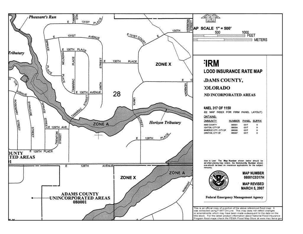
13 Villages at Riverdale 03/30/2017 Page 13 VI. REFERENCES 1. Urban Storm Drainage Criteria Manual, volumes 1, 2, and 3, Urban Drainage and Flood Control District, January Natural Resources Conservation Center Web Soil Survey, United States Department of Agriculture, site visited December Federal Emergency Management Agency Flood Insurance Rate Map, Community-Panel Numbers 08001C0317H, Map Revised March 5, Standards and Specifications for Design and Construction of Public and Private Improvements-October 2012, City of Thornton, CO. 5. Lower Brantner Gulch Major Drainageway Planning Update Preliminary Design Report, Love and Associates, January Brantner Gulch Northern Tributary Watersheds Hydrology Update, ICON Engineering, Inc., June Brantner Gulch and Tributaries Flood Hazard Area Delineation, Sellards and Grigg, Inc., January t f West 2 nd Avenue, Denver, Colorado
14 APPENDIX A Vicinity Map FEMA Flood Insurance Rate Map NRCS Soil Information Related Drainage Reports t f West 2 nd Avenue, Denver, Colorado
15
16

17 104 53' 49'' W Soil Map Adams County Area, Parts of Adams and Denver Counties, Colorado (Villages at Riverdale) ' 35'' W ' 49'' N 39 55' 49'' N 39 55' 42'' N ' 42'' N ' 49'' W N Map Scale: 1:1,580 if printed on A landscape (11" x 8.5") sheet. Meters Feet Map projection: Web Mercator Corner coordinates: WGS84 Edge tics: UTM Zone 13N WGS ' 35'' W Natural Resources Conservation Service Web Soil Survey National Cooperative Soil Survey 9/15/2016 Page 1 of 3
18 Soil Map Adams County Area, Parts of Adams and Denver Counties, Colorado (Villages at Riverdale) MAP LEGEND MAP INFORMATION Area of Interest (AOI) Area of Interest (AOI) Soils Soil Map Unit Polygons Soil Map Unit Lines Soil Map Unit Points Special Point Features Blowout Borrow Pit Clay Spot Closed Depression Gravel Pit Gravelly Spot Landfill Lava Flow Marsh or swamp Mine or Quarry Miscellaneous Water Perennial Water Rock Outcrop Saline Spot Sandy Spot Severely Eroded Spot Sinkhole Slide or Slip Sodic Spot Spoil Area Stony Spot Very Stony Spot Wet Spot Other Special Line Features Water Features Streams and Canals Transportation Rails Interstate Highways US Routes Major Roads Local Roads Background Aerial Photography The soil surveys that comprise your AOI were mapped at 1:20,000. Warning: Soil Map may not be valid at this scale. Enlargement of maps beyond the scale of mapping can cause misunderstanding of the detail of mapping and accuracy of soil line placement. The maps do not show the small areas of contrasting soils that could have been shown at a more detailed scale. Please rely on the bar scale on each map sheet for map measurements. Source of Map: Natural Resources Conservation Service Web Soil Survey URL: Coordinate System: Web Mercator (EPSG:3857) Maps from the Web Soil Survey are based on the Web Mercator projection, which preserves direction and shape but distorts distance and area. A projection that preserves area, such as the Albers equal-area conic projection, should be used if more accurate calculations of distance or area are required. This product is generated from the USDA-NRCS certified data as of the version date(s) listed below. Soil Survey Area: Adams County Area, Parts of Adams and Denver Counties, Colorado Survey Area Data: Version 12, Sep 22, 2015 Soil map units are labeled (as space allows) for map scales 1:50,000 or larger. Date(s) aerial images were photographed: 18, 2014 Aug 30, 2014 Sep The orthophoto or other base map on which the soil lines were compiled and digitized probably differs from the background imagery displayed on these maps. As a result, some minor shifting of map unit boundaries may be evident. Natural Resources Conservation Service Web Soil Survey National Cooperative Soil Survey 9/15/2016 Page 2 of 3

19 Soil Map Adams County Area, Parts of Adams and Denver Counties, Colorado Villages at Riverdale Map Unit Legend Natural Resources Conservation Service Web Soil Survey National Cooperative Soil Survey 9/15/2016 Page 3 of 3
20 APPENDIX B C Value Calculations SF2 & SF3 Rational Method Calculations Pond Calculations Riprap Street Capacity Calculations Inlet Calculations Storm Sewer Design t f West 2 nd Avenue, Denver, Colorado
21 PROJECT: Villages at Riverdale JOB NO.: CALC. BY: LMO DATE: 1/17/2017 Impervious Percentages - from Urban Drainage Table 6-3 Residential 45% Paved 100% Parks 10% Walks 90% Landscaping 2% Historic 2% SOIL TYPE: C or D (use equation from Table 6-4) PROPOSED COMPOSITE IMPERVIOUSNESS Areas (ac) Weighted Impervious and C Values Basin Area (ac) Residential Paved Parks Walks Landscaping Historic Imp. C 2 C 5 C 10 C 100 A % A % A % A % A % A % A % B % B % B % Pond % *Pond area does not include A4, B1, B2 or B3 JANSEN STRAWN COMPOSITE C VALUES - PROP 1/26/ SF2 SF3.xlsx
22 Calculated By: LMO STANDARD FORM SF-2 Project: Villages at Riverdale Date: 1/17/2017 TIME OF CONCENTRATION SUMMARY Job No.: Checked By: SUB-BASIN DATA INITIAL/OVERLAND TIME (t i ) TRAVEL TIME DESIG: i C 5 AREA LENGTH SLOPE t i LENGTH SLOPE VEL. t t COMP. TOT. LENGTH S o tc (Equation 6-5) Ac Ft % Min Ft Cv % FPS Min t c Ft % Min Min (1) (2) (3) (4) (5) (6) (7) (8) (9) (10) (11) (12) (13) (14) (15) (16) A A A A A A A (t t ) t c CHECK (URBANIZED BASINS) FINAL t c REMARKS B B B Equation Type of Land Surface Conveyance Facor, K Equation 6-4 Short Pasture and Lawns Nearly Bare Ground Grassed Waterway Paved Areas and Shallow Paved Swales Equation JANSEN STRAWN TOC 1/26/ SF2 SF3.xlsx
23 Calculated By: LMO STANDARD FORM SF-3 Project: Villages at Riverdale Date: 1/17/2017 STORM DRAINAGE SYSTEM DESIGN Job No.: Checked By: (RATIONAL METHOD PROCEDURE) Design Storm: 5-YR 5-yr, 1-hour rainfall= 1.38 BASIN DESIGN POINT AREA DESIGN AREA (AC) DIRECT RUNOFF TOTAL RUNOFF STREET RUNOFF COEFF t c (MIN) C * A (AC) I (IN/HR) Q (CFS) t c (MIN) S (C * A) (CA) I (IN/HR) Q (CFS) SLOPE (%) (2) (3) (4) (5) (6) (7) (8) (9) (10) (11) (12) (13) (14) (15) (16) (17) (18) (19) (20) (21) (22) A Flow from Basin A1 to DP1 A Flow from Basin A2 to DP1 STREET FLOW DESIGN FLOW (CFS) PIPE SLOPE (%) PIPE DIAM. (IN.) LENGTH (FT) % of flow captured by 10' sump DP1 VELOCITY (FPS) t t (MIN) REMARKS A Flow from Basin A3 to proposed 5' inlet at DP % of flow captured by 5' Type R sump DP5 A Flow from Basin A4 to existing 10' inlet at DP Flow captured by existing 10' inlet at DP6 A Flow from Basin A5 to DP % of flow captured by 5' Type R sump DP3 A Flow from Basin A6 to DP % of flow captured by 5' Type R sump DP4 A7 7/ Flow from Basin A7 directly to the proposed pond B Flow offsite directly to Horizon Tributary B Flow offsite to the south into E. 128th B Flow offsite to the south into E. 128th JANSEN STRAWN 5-YEAR 1/26/ SF2 SF3.xlsx
24 Calculated By: LMO STANDARD FORM SF-3 Project: Villages at Riverdale Date: 1/17/2017 STORM DRAINAGE SYSTEM DESIGN Job No.: Checked By: (RATIONAL METHOD PROCEDURE) Design Storm: 100-YR 100-yr, 1-hour rainfall= 2.69 BASIN DESIGN POINT AREA DESIGN AREA (AC) DIRECT RUNOFF TOTAL RUNOFF STREET RUNOFF COEFF t c (MIN) C * A (AC) I (IN/HR) Q (CFS) t c (MIN) S (C * A) (CA) I (IN/HR) Q (CFS) SLOPE (%) (2) (3) (4) (5) (6) (7) (8) (9) (10) (11) (12) (13) (14) (15) (16) (17) (18) (19) (20) (21) (22) A Flow from Basin A1 to DP1 A Flow from Basin A2 to DP1 STREET FLOW DESIGN FLOW (CFS) SLOPE (%) PIPE DIAM. (IN.) Total DP Total flow captured by 10' sump DP % Overflow to DP5 A Flow from Basin A3 to proposed 5' inlet at DP5 PIPE LENGTH (FT) VELOCITY (FPS) DP1 overflow and Basin A3 captured by 5' Type R DP5 t t (MIN) REMARKS A Flow from Basin A4 to existing 10' inlet at DP Flow captured by existing 10' inlet at DP6 A Flow from Basin A5 to DP % of flow captured by 5' Type R sump DP3 A Flow from Basin A6 to DP % of flow captured by 5' Type R sump DP4 A7 7/ Flow from Basin A7 directly to the proposed pond B Flow offsite directly to Horizon Tributary B Flow offsite to the south into E. 128th B Flow offsite to the south into E. 128th Total flow to Pond A (Tc from Hydraflow) JANSEN STRAWN 100-YEAR 1/26/ SF2 SF3.xlsx
25 BASIN LABEL DESIGN POINT RUNOFF SUMMARY LOCAL (CFS) ACCUMULATIVE (CFS) AREA Q5 Q 100 Q5 Q 100 A A A A A A A7 7/ B B
26 DETENTION BASIN STAGE-STORAGE TABLE BUILDER Project: Villages at Riverdale Basin ID: Example Zone Configuration (Retention Pond) Depth Increment = 0.1 ft Stage - Storage Description Required Volume Calculation Micropool Selected BMP Type = EDB , Watershed Area = 7.23 acres , , Watershed Length = 900 ft , , Watershed Slope = ft/ft , , Watershed Imperviousness = 49.00% percent , , Percentage Hydrologic Soil Group A = 0.0% percent , , Percentage Hydrologic Soil Group B = 0.0% percent , , Percentage Hydrologic Soil Groups C/D = 100.0% percent , , Desired WQCV Drain Time = 40.0 hours Location for 1-hr Rainfall Depths = Thornton - Thornton City Office Water Quality Capture Volume (WQCV) = acre-feet Optional User Input Excess Urban Runoff Volume (EURV) = acre-feet 1-hr Precipitation 2-yr Runoff Volume (P1 = 0.95 in.) = acre-feet inches 5-yr Runoff Volume (P1 = 1.35 in.) = acre-feet inches 10-yr Runoff Volume (P1 = 1.61 in.) = acre-feet inches 25-yr Runoff Volume (P1 = 2.03 in.) = acre-feet inches 50-yr Runoff Volume (P1 = 2.32 in.) = acre-feet inches 100-yr Runoff Volume (P1 = 2.66 in.) = acre-feet inches 500-yr Runoff Volume (P1 = 3.33 in.) = acre-feet inches Approximate 2-yr Detention Volume = acre-feet Approximate 5-yr Detention Volume = acre-feet Approximate 10-yr Detention Volume = acre-feet Approximate 25-yr Detention Volume = acre-feet Approximate 50-yr Detention Volume = acre-feet Approximate 100-yr Detention Volume = acre-feet Stage-Storage Calculation Zone 1 Volume (WQCV) = acre-feet Zone 2 Volume (EURV - Zone 1) = acre-feet Zone 3 Volume (100-year - Zones 1 & 2) = acre-feet Total Detention Basin Volume = acre-feet Initial Surcharge Volume (ISV) = user ft^3 Initial Surcharge Depth (ISD) = user ft Total Available Detention Depth (H total ) = user ft Depth of Trickle Channel (H TC ) = user ft Slope of Trickle Channel (S TC ) = user ft/ft Slopes of Main Basin Sides (S main ) = user H:V Basin Length-to-Width Ratio (R L/W ) = user Initial Surcharge Area (A ISV ) = user ft^2 Surcharge Volume Length (L ISV ) = user ft Surcharge Volume Width (W ISV ) = user ft Depth of Basin Floor (H FLOOR ) = user ft Length of Basin Floor (L FLOOR ) = user ft Width of Basin Floor (W FLOOR ) = user ft Area of Basin Floor (A FLOOR ) = user ft^2 Volume of Basin Floor (V FLOOR ) = user ft^3 Depth of Main Basin (H MAIN ) = user ft Length of Main Basin (L MAIN ) = user ft Width of Main Basin (W MAIN ) = user ft Area of Main Basin (A MAIN ) = user ft^2 Volume of Main Basin (V MAIN ) = user ft^3 Calculated Total Basin Volume (V total ) = user acre-feet Stage (ft) Optional Override Stage (ft) Length (ft) Width (ft) Area (ft^2) Optional Override Area (ft^2) Area (acre) Volume (ft^3) Volume (ac-ft) Pond A UD Detention, Basin 1/26/2017, 1:48 PM
27 Area (acres) Volume (ac-ft) Length, Width (ft.) Area (sq.ft.) DETENTION BASIN STAGE-STORAGE TABLE BUILDER 20 1 User Defined Stage-Area Boolean for Message 1 Equal Stage-Area Inputs Watershed L:W 1 CountA Calc_S_TC 0.55 H_FLOOR 300 L_FLOOR_OTHER ISV 0.00 ISV 0.00 Floor 0.00 Floor 2.09 Zone 1 (WQCV) 2.09 Zone 1 (WQCV) 3.23 Zone 2 (EURV) 3.23 Zone 2 (EURV) 4.77 Zone 3 (100-year 4.77 Zone 3 (100-year) Stage (ft) Length (ft) Width (ft) Area (sq.ft.) Stage (ft.) Area (acres) Volume (ac-ft) Pond A UD Detention, Basin 1/26/2017, 1:48 PM
28 Detention Basin Outlet Structure Design Project: Villages at Riverdale Basin ID: Stage (ft) Zone Volume (ac-ft) Outlet Type Zone 1 (WQCV) Orifice Plate Zone 2 (EURV) Orifice Plate Zone 3 (100-year) Weir&Pipe (Circular) Example Zone Configuration (Retention Pond) Total User Input: Orifice at Underdrain Outlet (typically used to drain WQCV in a Filtration BMP) Calculated Parameters for Underdrain Underdrain Orifice Invert Depth = N/A ft (distance below the filtration media surface) Underdrain Orifice Area = N/A ft 2 Underdrain Orifice Diameter = N/A inches Underdrain Orifice Centroid = N/A feet User Input: Orifice Plate with one or more orifices or Elliptical Slot Weir (typically used to drain WQCV and/or EURV in a sedimentation BMP) Calculated Parameters for Plate Invert of Lowest Orifice = 0.00 ft (relative to basin bottom at Stage = 0 ft) WQ Orifice Area per Row = 4.861E-03 ft 2 Depth at top of Zone using Orifice Plate = 3.23 ft (relative to basin bottom at Stage = 0 ft) Elliptical Half-Width = N/A feet Orifice Plate: Orifice Vertical Spacing = inches Elliptical Slot Centroid = N/A feet Orifice Plate: Orifice Area per Row = 0.70 sq. inches (diameter = 15/16 inch) Elliptical Slot Area = N/A ft 2 User Input: Stage and Total Area of Each Orifice Row (numbered from lowest to highest) Row 1 (required) Row 2 (optional) Row 3 (optional) Row 4 (optional) Row 5 (optional) Row 6 (optional) Row 7 (optional) Row 8 (optional) Stage of Orifice Centroid (ft) Orifice Area (sq. inches) Stage of Orifice Centroid (ft) Orifice Area (sq. inches) Row 9 (optional) Row 10 (optional) Row 11 (optional) Row 12 (optional) Row 13 (optional) Row 14 (optional) Row 15 (optional) Row 16 (optional) User Input: Vertical Orifice (Circular or Rectangular) Calculated Parameters for Vertical Orifice Not Selected Not Selected Not Selected Not Selected Invert of Vertical Orifice = N/A N/A ft (relative to basin bottom at Stage = 0 ft) Vertical Orifice Area = N/A N/A ft 2 Depth at top of Zone using Vertical Orifice = N/A N/A ft (relative to basin bottom at Stage = 0 ft) Vertical Orifice Centroid = N/A N/A feet Vertical Orifice Diameter = N/A N/A inches User Input: Overflow Weir (Dropbox) and Grate (Flat or Sloped) Calculated Parameters for Overflow Weir Zone 3 Weir Not Selected Zone 3 Weir Not Selected Overflow Weir Front Edge Height, Ho = 3.23 N/A ft (relative to basin bottom at Stage = 0 ft) Height of Grate Upper Edge, H t = 4.77 N/A feet Overflow Weir Front Edge Length = 4.00 N/A feet Over Flow Weir Slope Length = 6.34 N/A feet Overflow Weir Slope = 4.00 N/A H:V (enter zero for flat grate) Grate Open Area / 100-yr Orifice Area = N/A should be > 4 Horiz. Length of Weir Sides = 6.15 N/A feet Overflow Grate Open Area w/o Debris = N/A ft 2 Overflow Grate Open Area % = 70% N/A %, grate open area/total area Overflow Grate Open Area w/ Debris = 8.87 N/A ft 2 Debris Clogging % = 50% N/A % User Input: Outlet Pipe w/ Flow Restriction Plate (Circular Orifice, Restrictor Plate, or Rectangular Orifice) Calculated Parameters for Outlet Pipe w/ Flow Restriction Plate Zone 3 Circular Not Selected Zone 3 Circular Not Selected Depth to Invert of Outlet Pipe = 2.71 N/A ft (distance below basin bottom at Stage = 0 ft) Outlet Orifice Area = 0.72 N/A ft 2 Circular Orifice Diameter = N/A inches Outlet Orifice Centroid = 0.48 N/A feet Half-Central Angle of Restrictor Plate on Pipe = N/A N/A radians User Input: Emergency Spillway (Rectangular or Trapezoidal) Calculated Parameters for Spillway Spillway Invert Stage= 5.50 ft (relative to basin bottom at Stage = 0 ft) Spillway Design Flow Depth= 0.34 feet Spillway Crest Length = feet Stage at Top of Freeboard = 6.84 feet Spillway End Slopes = 4.00 H:V Basin Area at Top of Freeboard = 0.39 acres Freeboard above Max Water Surface = 1.00 feet Routed Hydrograph Results Design Storm Return Period = WQCV EURV 2 Year 5 Year 10 Year 25 Year 50 Year 100 Year 500 Year One-Hour Rainfall Depth (in) = Calculated Runoff Volume (acre-ft) = OPTIONAL Override Runoff Volume (acre-ft) = Inflow Hydrograph Volume (acre-ft) = Predevelopment Unit Peak Flow, q (cfs/acre) = Predevelopment Peak Q (cfs) = Peak Inflow Q (cfs) = Peak Outflow Q (cfs) = Ratio Peak Outflow to Predevelopment Q = N/A N/A N/A Structure Controlling Flow = Plate Plate Plate Overflow Grate 1 Overflow Grate 1 Overflow Grate 1 Outlet Plate 1 Outlet Plate 1 Spillway Max Velocity through Grate 1 (fps) = N/A N/A N/A Max Velocity through Grate 2 (fps) = N/A N/A N/A N/A N/A N/A N/A N/A N/A Time to Drain 97% of Inflow Volume (hours) = Time to Drain 99% of Inflow Volume (hours) = Maximum Ponding Depth (ft) = Area at Maximum Ponding Depth (acres) = Maximum Volume Stored (acre-ft) =
![AREA [ft^2], VOLUME [ft^3] OUTFLOW [cfs] PONDING DEPTH [ft] FLOW [cfs] Detention Basin Outlet Structure Design 40 35 30 25 20 15 10 5 COUNTA for Basin Tab = 1 Ao Dia WQ Plate Type Vert Orifice 1 Vert](/docs-images/82/86170965/images/29-1.jpg "Orifice 2 500YR IN Count_Underdrain = 0 0.11 eter = 3/8 inch) 2 1 1 500YR OUT 100YR IN 100YR OUT 50YR IN Count_WQPlate = 1 0.14 eter = 7/16 inch) Count_VertOrifice1 = 0 0.")
29 AREA [ft^2], VOLUME [ft^3] OUTFLOW [cfs] PONDING DEPTH [ft] FLOW [cfs] Detention Basin Outlet Structure Design COUNTA for Basin Tab = 1 Ao Dia WQ Plate Type Vert Orifice 1 Vert Orifice 2 500YR IN Count_Underdrain = eter = 3/8 inch) YR OUT 100YR IN 100YR OUT 50YR IN Count_WQPlate = eter = 7/16 inch) Count_VertOrifice1 = eter = 1/2 inch) Outlet Plate 1 Outlet Plate 2 Drain Time Message Boolean Count_VertOrifice2 = eter = 9/16 inch) 2 1 5yr, <72hr 0 50YR OUT 25YR IN 25YR OUT 10YR IN Count_Weir1 = eter = 5/8 inch) >5yr, <120hr 0 Count_Weir2 = er = 11/16 inch) Max Depth Row Count_OutletPipe1 = eter = 3/4 inch) WQCV 202 Watershed Constraint Check 10YR OUT 5YR IN Count_OutletPipe2 = er = 13/16 inch) 2 Year 283 Slope COUNTA_2 (Standard FSD Setup)= eter = 7/8 inch) EURV 316 Shape YR OUT MaxPondDepth_Error? FALSE 0.67 er = 15/16 inch) 5 Year 351 2YR IN Hidden Parameters & Calculations 0.76 meter = 1 inch) 10 Year 374 Spillway Depth 2YR OUT EURV IN 0.86 = 1-1/16 inches) 25 Year WQ Plate Flow at 100yr depth = = 1-1/8 inches) 50 Year 428 EURV OUT WQCV IN WQCV OUT CLOG #1= 35% 1.08 = 1-3/16 inches) 100 Year Z1_Boolean C dw #1 = = 1-1/4 inches) 500 Year Z2_Boolean C do #1 = = 1-5/16 inches) Zone3_Pulldown Message 1 Z3_Boolean Overflow Weir #1 Angle = = 1-3/8 inches) 1 Opening Message CLOG #2= #VALUE! 1.59 = 1-7/16 inches) Draintime Running C dw #2 = #VALUE! 1.73 = 1-1/2 inches) Outlet Boolean Outlet Rank Total (1 to 4) C do #2 = #VALUE! 1.88 = 1-9/16 inches) Vertical Orifice Overflow Weir #2 Angle = #VALUE! 2.03 = 1-5/8 inches) Vertical Orifice Boolean 0 Underdrain Q at 100yr depth = /16 inches) Overflow Weir Max Depth 10 VertOrifice1 Q at 100yr depth = = 1-3/4 inches) TIME [hr] Overflow Weir yr Depth VertOrifice2 Q at 100yr depth = /16 inches) Outlet Pipe Freeboard EURV_draintime_user = 2.72 = 1-7/8 inches) Outlet Pipe Spillway 500YR Count_User_Hydrographs /16 inches) 0 Spillway Length 100YR CountA_3 (EURV & 100yr) = eter = 2 inches) Button Visibility Boolean FALSE Time Interval 50YR CountA_4 (100yr Only) = gular openings) 1 Button_Trigger 25YR 10YR 5YR 2YR EURV WQCV 0 Underdrain 1 WQCV Plate 0 EURV-WQCV Plate 0 EURV-WQCV VertOrifice 1 Outlet 90% Qpeak 0 Outlet Undetained DRAIN TIME [hr] 90,000 80,000 70,000 60,000 User Area [ft^2] Interpolated Area [ft^2] Summary Area [ft^2] Volume [ft^3] Summary Volume [ft^3] Outflow [cfs] Summary Outflow [cfs] , , ,000 20, , PONDING DEPTH [ft] S-A-V-D Chart Axis Override X-axis Left Y-Axis Right Y-Axis minimum bound maximum bound
30 Detention Basin Outlet Structure Design Outflow Hydrograph Workbook Filename: Storm Inflow Hydrographs The user can override the calculated inflow hydrographs from this workbook with inflow hydrographs developed in a separate program. SOURCE WORKBOOK WORKBOOK WORKBOOK WORKBOOK WORKBOOK WORKBOOK WORKBOOK WORKBOOK WORKBOOK Time Interval TIME WQCV [cfs] EURV [cfs] 2 Year [cfs] 5 Year [cfs] 10 Year [cfs] 25 Year [cfs] 50 Year [cfs] 100 Year [cfs] 500 Year [cfs] 5.64 min 0:00: :05: Hydrograph 0:11: Constant 0:16: :22: :28: :33: :39: :45: :50: :56: :02: :07: :13: :18: :24: :30: :35: :41: :47: :52: :58: :04: :09: :15: :21: :26: :32: :37: :43: :49: :54: :00: :06: :11: :17: :23: :28: :34: :39: :45: :51: :56: :02: :08: :13: :19: :25: :30: :36: :42: :47: :53: :58: :04: :10: :15: :21: :27: :32: :38: :44: :49: :55: :00: :06: :12: :17: :23: :29: :34: :40: :46:
31 Detention Basin Outlet Structure Design Summary Stage-Area-Volume-Discharge Relationships The user can create a summary S-A-V-D by entering the desired stage increments and the remainder of the table will populate automatically. The user should graphically compare the summary S-A-V-D table to the full S-A-V-D table in the chart to confirm it captures all key transition points. Stage - Storage Description Stage Area Area Volume Volume Total Outflow [ft] [ft^2] [acres] [ft^3] [ac-ft] [cfs] For best results, include the stages of all grade slope changes (e.g. ISV and Floor) from the S-A-V table on Sheet 'Basin'. Also include the inverts of all outlets (e.g. vertical orifice, overflow grate, and spillway, where applicable).
32 PROJECT : Villages at Riverdale DATE : 3/29/2017 PROJECT NO. : BY : MDS Pond A-Overflow Weirs POND WEIR 2xQ 100 = cfs Try Weir Release: Q 100 = Weir Equation => Q=CLH 3/ cfs C = 3.00 L = ft Flow Depth = 0.56 ft USE: Say 41' Spillway Width JANSEN STRAWN CONSULTING ENGINEERS 45 West 2nd Ave. - Denver, CO p: f:
33 Determination of Culvert Headwater and Outlet Protection Project: Villages at Riverdale Basin ID: From the South - Pond Outfall Soil Choose Type: One: Sandy Non-Sandy Supercritical Flow! Using Da to calculate protection type Design Information (Input): Design Discharge Q = cfs Circular Culvert: Barrel Diameter in Inches D = 24 inches Inlet Edge Type (Choose from pull-down list) Box Culvert: OR Barrel Height (Rise) in Feet Height (Rise) = ft Barrel Width (Span) in Feet Width (Span) = ft Inlet Edge Type (Choose from pull-down list) Number of Barrels No = 1 Inlet Elevation Elev IN = ft Outlet Elevation OR Slope Elev OUT = ft Culvert Length L = ft Manning's Roughness n = Bend Loss Coefficient k b = 0 Exit Loss Coefficient k x = 1 Tailwater Surface Elevation Elev Y t = ft Max Allowable Channel Velocity V = 7 ft/s Required Protection (Output): Tailwater Surface Height Y t = 0.80 ft Flow Area at Max Channel Velocity A t = 2.85 ft 2 Culvert Cross Sectional Area Available A = 3.14 ft 2 Entrance Loss Coefficient k e = 0.50 Friction Loss Coefficient k f = 0.47 Sum of All Losses Coefficients k s = 1.97 ft Culvert Normal Depth Y n = 0.73 ft Culvert Critical Depth Y c = 1.61 ft Tailwater Depth for Design d = 1.80 ft Adjusted Diameter OR Adjusted Rise D a = 1.37 ft Expansion Factor 1/(2*tan(Θ)) = 6.20 Flow/Diameter 2.5 OR Flow/(Span * Rise 1.5 ) Q/D^2.5 = 3.53 ft 0.5 /s Froude Number Fr = 4.58 Supercritical! Tailwater/Adjusted Diameter OR Tailwater/Adjusted Rise Yt/D = 0.59 Inlet Control Headwater HW I = 2.90 ft Outlet Control Headwater HW O = Design Headwater Elevation HW = 5, ft Headwater/Diameter OR Headwater/Rise Ratio HW/D = 1.45 Minimum Theoretical Riprap Size d 50 = 7 in Nominal Riprap Size d 50 = 9 in UDFCD Riprap Type Type = L Length of Protection L p = 10 ft Width of Protection T = 4 ft
34 Determination of Culvert Headwater and Outlet Protection Project: Villages at Riverdale Basin ID: From the West - Pond Outfall Soil Choose Type: One: Sandy Non-Sandy Supercritical Flow! Using Da to calculate protection type Design Information (Input): Design Discharge Q = cfs Circular Culvert: Barrel Diameter in Inches D = 18 inches Inlet Edge Type (Choose from pull-down list) Box Culvert: OR Barrel Height (Rise) in Feet Height (Rise) = ft Barrel Width (Span) in Feet Width (Span) = ft Inlet Edge Type (Choose from pull-down list) Number of Barrels No = 1 Inlet Elevation Elev IN = ft Outlet Elevation OR Slope Elev OUT = ft Culvert Length L = ft Manning's Roughness n = Bend Loss Coefficient k b = 0 Exit Loss Coefficient k x = 1 Tailwater Surface Elevation Elev Y t = ft Max Allowable Channel Velocity V = 5 ft/s Required Protection (Output): Tailwater Surface Height Y t = 0.60 ft Flow Area at Max Channel Velocity A t = 2.60 ft 2 Culvert Cross Sectional Area Available A = 1.77 ft 2 Entrance Loss Coefficient k e = 0.50 Friction Loss Coefficient k f = 3.53 Sum of All Losses Coefficients k s = 5.03 ft Culvert Normal Depth Y n = 0.82 ft Culvert Critical Depth Y c = 1.35 ft Tailwater Depth for Design d = 1.43 ft Adjusted Diameter OR Adjusted Rise D a = 1.16 ft Expansion Factor 1/(2*tan(Θ)) = 4.04 Flow/Diameter 2.5 OR Flow/(Span * Rise 1.5 ) Q/D^2.5 = 4.72 ft 0.5 /s Froude Number Fr = 2.87 Supercritical! Tailwater/Adjusted Diameter OR Tailwater/Adjusted Rise Yt/D = 0.52 Inlet Control Headwater HW I = 3.15 ft Outlet Control Headwater HW O = Design Headwater Elevation HW = 5, ft Headwater/Diameter OR Headwater/Rise Ratio HW/D = 2.10 HW/D > 1.5! Minimum Theoretical Riprap Size d 50 = 6 in Nominal Riprap Size d 50 = 9 in UDFCD Riprap Type Type = L Length of Protection L p = 12 ft Width of Protection T = 5 ft
35 Hydraulic Structures Chapter 9 Figure Low tailwater riprap basin 9-74 Urban Drainage and Flood Control District November 2016 Urban Storm Drainage Criteria Manual Volume 2
36 Overflow Spillway Riprap Calculations Where: = median rock size in inches qt = equivalent unit discharge in ft^3/sec/ft = (( h.. (3.95(10 The unit discharge was divided by the width of the spillway, 42. = = 0.62 Sch = chute bed slope in ft/ft =! (0.62 (0.25/. (3.95(10 #. D50 = 2.81 inches Per Volume 1, Section of the USDCM, you must increase the D50 rock size by 30% when specifying standard UDFCD rip-rap gradations and then use a factor of safety of 1.5 after applying the 30% increase. = $(2.81 &'.(1.30(1.5 = 5.50 &'h) Type M Riprap was used for the overflow spillway.
37 Version 4.04 Released November 2016 Inlet Management Worksheet Protected INLET NAME Drainage Point 5 Drainage Point 3 Drainage Point 4 Drainage Point 1 ed Site Type (Urban or Rural) URBAN URBAN URBAN URBAN Inlet Application (Street or Area) STREET STREET STREET STREET Hydraulic Condition In Sump In Sump In Sump In Sump Inlet Type CDOT Type R Curb Opening CDOT Type R Curb Opening CDOT Type R Curb Opening CDOT Type R Curb Opening USER-DEFINED INPUT User-Defined Design Flows Minor Q Known (cfs) Major Q Known (cfs) Bypass (Carry-Over) Flow from Upstream Receive Bypass Flow from: Minor Bypass Flow Received, Q b (cfs) Major Bypass Flow Received, Q b (cfs) User-Defined No Bypass Flow Received No Bypass Flow Received No Bypass Flow Received Watershed Characteristics Subcatchment Area (acres) Percent Impervious NRCS Soil Type Watershed Profile Overland Slope (ft/ft) Overland Length (ft) Channel Slope (ft/ft) Channel Length (ft) Minor Storm Rainfall Input Design Storm Return Period, T r (years) One-Hour Precipitation, P 1 (inches) Major Storm Rainfall Input Design Storm Return Period, T r (years) One-Hour Precipitation, P 1 (inches) CALCULATED OUTPUT Minor Total Design Peak Flow, Q (cfs) Major Total Design Peak Flow, Q (cfs) Minor Flow Bypassed Downstream, Q b (cfs) Major Flow Bypassed Downstream, Q b (cfs) N/A N/A N/A N/A N/A N/A N/A N/A
38 Project: Inlet ID: Version 4.04 Released November 2016 ALLOWABLE CAPACITY FOR ONE-HALF OF STREET (Minor & Major Storm) (Based on Regulated Criteria for Maximum Allowable Flow Depth and Spread) Villages at Riverdale Drainage Point 1 Gutter Geometry (Enter data in the blue cells) Maximum Allowable Width for Spread Behind Curb T BACK = 8.0 ft Side Slope Behind Curb (leave blank for no conveyance credit behind curb) S BACK = ft/ft Manning's Roughness Behind Curb (typically between and 0.020) n BACK = Height of Curb at Gutter Flow Line H CURB = 6.00 inches Distance from Curb Face to Street Crown T CROWN = 17.0 ft Gutter Width W = 2.00 ft Street Transverse Slope S X = ft/ft Gutter Cross Slope (typically 2 inches over 24 inches or ft/ft) S W = ft/ft Street Longitudinal Slope - Enter 0 for sump condition S O = ft/ft Manning's Roughness for Street Section (typically between and 0.020) n STREET = Minor Storm Major Storm Max. Allowable Spread for Minor & Major Storm T MAX = ft Max. Allowable Depth at Gutter Flowline for Minor & Major Storm d MAX = inches Allow Flow Depth at Street Crown (leave blank for no) check = yes MINOR STORM Allowable Capacity is based on Depth Criterion Minor Storm Major Storm MAJOR STORM Allowable Capacity is based on Depth Criterion Q allow = SUMP SUMP cfs Inlets.xlsm, Drainage Point 1 1/17/2017, 1:29 PM
39 INLET IN A SUMP OR SAG LOCATION Version 4.04 Released November 2016 H-Curb W W P H-Vert Lo (C) Wo Lo (G) Design Information (Input) MINOR MAJOR CDOT Type R Curb Opening Type of Inlet Type = CDOT Type R Curb Opening Local Depression (additional to continuous gutter depression 'a' from 'Q-Allow') a local = inches Number of Unit Inlets (Grate or Curb Opening) No = 1 1 Water Depth at Flowline (outside of local depression) Ponding Depth = inches Grate Information MINOR MAJOR Override Depths Length of a Unit Grate L o (G) = N/A N/A feet Width of a Unit Grate W o = N/A N/A feet Area Opening Ratio for a Grate (typical values ) A ratio = N/A N/A Clogging Factor for a Single Grate (typical value ) C f (G) = N/A N/A Grate Weir Coefficient (typical value ) C w (G) = N/A N/A Grate Orifice Coefficient (typical value ) C o (G) = N/A N/A Curb Opening Information MINOR MAJOR Length of a Unit Curb Opening L o (C) = feet Height of Vertical Curb Opening in Inches H vert = inches Height of Curb Orifice Throat in Inches H throat = inches Angle of Throat (see USDCM Figure ST-5) Theta = degrees Side Width for Depression Pan (typically the gutter width of 2 feet) W p = feet Clogging Factor for a Single Curb Opening (typical value 0.10) C f (C) = Curb Opening Weir Coefficient (typical value ) C w (C) = Curb Opening Orifice Coefficient (typical value ) C o (C) = Low Head Performance Reduction (Calculated) MINOR MAJOR Depth for Grate Midwidth d Grate = N/A N/A ft Depth for Curb Opening Weir Equation d Curb = ft Combination Inlet Performance Reduction Factor for Long Inlets RF Combination = Curb Opening Performance Reduction Factor for Long Inlets RF Curb = Grated Inlet Performance Reduction Factor for Long Inlets RF Grate = N/A N/A MINOR MAJOR Total Inlet Interception Capacity (assumes clogged condition) Q a = cfs WARNING: Inlet Capacity less than Q Peak for Major Storm Q PEAK REQUIRED = cfs Inlets.xlsm, Drainage Point 1 1/17/2017, 1:29 PM
40 Project: Inlet ID: Version 4.04 Released November 2016 ALLOWABLE CAPACITY FOR ONE-HALF OF STREET (Minor & Major Storm) (Based on Regulated Criteria for Maximum Allowable Flow Depth and Spread) Villages at Riverdale Drainage Point 3 Gutter Geometry (Enter data in the blue cells) Maximum Allowable Width for Spread Behind Curb T BACK = 8.0 ft Side Slope Behind Curb (leave blank for no conveyance credit behind curb) S BACK = ft/ft Manning's Roughness Behind Curb (typically between and 0.020) n BACK = Height of Curb at Gutter Flow Line H CURB = 6.00 inches Distance from Curb Face to Street Crown T CROWN = 17.0 ft Gutter Width W = 2.00 ft Street Transverse Slope S X = ft/ft Gutter Cross Slope (typically 2 inches over 24 inches or ft/ft) S W = ft/ft Street Longitudinal Slope - Enter 0 for sump condition S O = ft/ft Manning's Roughness for Street Section (typically between and 0.020) n STREET = Minor Storm Major Storm Max. Allowable Spread for Minor & Major Storm T MAX = ft Max. Allowable Depth at Gutter Flowline for Minor & Major Storm d MAX = inches Allow Flow Depth at Street Crown (leave blank for no) check = yes MINOR STORM Allowable Capacity is based on Depth Criterion Minor Storm Major Storm MAJOR STORM Allowable Capacity is based on Depth Criterion Q allow = SUMP SUMP cfs Inlets.xlsm, Drainage Point 3 1/17/2017, 1:29 PM
41 INLET IN A SUMP OR SAG LOCATION Version 4.04 Released November 2016 H-Curb W W P H-Vert Lo (C) Wo Lo (G) Design Information (Input) MINOR MAJOR CDOT Type R Curb Opening Type of Inlet Type = CDOT Type R Curb Opening Local Depression (additional to continuous gutter depression 'a' from 'Q-Allow') a local = inches Number of Unit Inlets (Grate or Curb Opening) No = 1 1 Water Depth at Flowline (outside of local depression) Ponding Depth = inches Grate Information MINOR MAJOR Override Depths Length of a Unit Grate L o (G) = N/A N/A feet Width of a Unit Grate W o = N/A N/A feet Area Opening Ratio for a Grate (typical values ) A ratio = N/A N/A Clogging Factor for a Single Grate (typical value ) C f (G) = N/A N/A Grate Weir Coefficient (typical value ) C w (G) = N/A N/A Grate Orifice Coefficient (typical value ) C o (G) = N/A N/A Curb Opening Information MINOR MAJOR Length of a Unit Curb Opening L o (C) = feet Height of Vertical Curb Opening in Inches H vert = inches Height of Curb Orifice Throat in Inches H throat = inches Angle of Throat (see USDCM Figure ST-5) Theta = degrees Side Width for Depression Pan (typically the gutter width of 2 feet) W p = feet Clogging Factor for a Single Curb Opening (typical value 0.10) C f (C) = Curb Opening Weir Coefficient (typical value ) C w (C) = Curb Opening Orifice Coefficient (typical value ) C o (C) = Low Head Performance Reduction (Calculated) MINOR MAJOR Depth for Grate Midwidth d Grate = N/A N/A ft Depth for Curb Opening Weir Equation d Curb = ft Combination Inlet Performance Reduction Factor for Long Inlets RF Combination = Curb Opening Performance Reduction Factor for Long Inlets RF Curb = Grated Inlet Performance Reduction Factor for Long Inlets RF Grate = N/A N/A MINOR MAJOR Total Inlet Interception Capacity (assumes clogged condition) Q a = cfs Inlet Capacity IS GOOD for Minor and Major Storms(>Q PEAK) Q PEAK REQUIRED = cfs Inlets.xlsm, Drainage Point 3 1/17/2017, 1:29 PM
42 Project: Inlet ID: Version 4.04 Released November 2016 ALLOWABLE CAPACITY FOR ONE-HALF OF STREET (Minor & Major Storm) (Based on Regulated Criteria for Maximum Allowable Flow Depth and Spread) Villages at Riverdale Drainage Point 4 Gutter Geometry (Enter data in the blue cells) Maximum Allowable Width for Spread Behind Curb T BACK = 8.0 ft Side Slope Behind Curb (leave blank for no conveyance credit behind curb) S BACK = ft/ft Manning's Roughness Behind Curb (typically between and 0.020) n BACK = Height of Curb at Gutter Flow Line H CURB = 6.00 inches Distance from Curb Face to Street Crown T CROWN = 17.0 ft Gutter Width W = 2.00 ft Street Transverse Slope S X = ft/ft Gutter Cross Slope (typically 2 inches over 24 inches or ft/ft) S W = ft/ft Street Longitudinal Slope - Enter 0 for sump condition S O = ft/ft Manning's Roughness for Street Section (typically between and 0.020) n STREET = Minor Storm Major Storm Max. Allowable Spread for Minor & Major Storm T MAX = ft Max. Allowable Depth at Gutter Flowline for Minor & Major Storm d MAX = inches Allow Flow Depth at Street Crown (leave blank for no) check = yes MINOR STORM Allowable Capacity is based on Depth Criterion Minor Storm Major Storm MAJOR STORM Allowable Capacity is based on Depth Criterion Q allow = SUMP SUMP cfs Inlets.xlsm, Drainage Point 4 1/17/2017, 1:29 PM
43 INLET IN A SUMP OR SAG LOCATION Version 4.04 Released November 2016 H-Curb W W P H-Vert Lo (C) Wo Lo (G) Design Information (Input) MINOR MAJOR CDOT Type R Curb Opening Type of Inlet Type = CDOT Type R Curb Opening Local Depression (additional to continuous gutter depression 'a' from 'Q-Allow') a local = inches Number of Unit Inlets (Grate or Curb Opening) No = 1 1 Water Depth at Flowline (outside of local depression) Ponding Depth = inches Grate Information MINOR MAJOR Override Depths Length of a Unit Grate L o (G) = N/A N/A feet Width of a Unit Grate W o = N/A N/A feet Area Opening Ratio for a Grate (typical values ) A ratio = N/A N/A Clogging Factor for a Single Grate (typical value ) C f (G) = N/A N/A Grate Weir Coefficient (typical value ) C w (G) = N/A N/A Grate Orifice Coefficient (typical value ) C o (G) = N/A N/A Curb Opening Information MINOR MAJOR Length of a Unit Curb Opening L o (C) = feet Height of Vertical Curb Opening in Inches H vert = inches Height of Curb Orifice Throat in Inches H throat = inches Angle of Throat (see USDCM Figure ST-5) Theta = degrees Side Width for Depression Pan (typically the gutter width of 2 feet) W p = feet Clogging Factor for a Single Curb Opening (typical value 0.10) C f (C) = Curb Opening Weir Coefficient (typical value ) C w (C) = Curb Opening Orifice Coefficient (typical value ) C o (C) = Low Head Performance Reduction (Calculated) MINOR MAJOR Depth for Grate Midwidth d Grate = N/A N/A ft Depth for Curb Opening Weir Equation d Curb = ft Combination Inlet Performance Reduction Factor for Long Inlets RF Combination = Curb Opening Performance Reduction Factor for Long Inlets RF Curb = Grated Inlet Performance Reduction Factor for Long Inlets RF Grate = N/A N/A MINOR MAJOR Total Inlet Interception Capacity (assumes clogged condition) Q a = cfs Inlet Capacity IS GOOD for Minor and Major Storms(>Q PEAK) Q PEAK REQUIRED = cfs Inlets.xlsm, Drainage Point 4 1/17/2017, 1:29 PM
 (Based on Regulated Criteria for Maximum Allowable Flow Depth and Spread) Villages at Riverdale Drainage")
44 Project: Inlet ID: Version 4.04 Released November 2016 ALLOWABLE CAPACITY FOR ONE-HALF OF STREET (Minor & Major Storm) (Based on Regulated Criteria for Maximum Allowable Flow Depth and Spread) Villages at Riverdale Drainage Point 5 Gutter Geometry (Enter data in the blue cells) Maximum Allowable Width for Spread Behind Curb T BACK = 8.0 ft Side Slope Behind Curb (leave blank for no conveyance credit behind curb) S BACK = ft/ft Manning's Roughness Behind Curb (typically between and 0.020) n BACK = Height of Curb at Gutter Flow Line H CURB = 6.00 inches Distance from Curb Face to Street Crown T CROWN = 14.3 ft Gutter Width W = 2.00 ft Street Transverse Slope S X = ft/ft Gutter Cross Slope (typically 2 inches over 24 inches or ft/ft) S W = ft/ft Street Longitudinal Slope - Enter 0 for sump condition S O = ft/ft Manning's Roughness for Street Section (typically between and 0.020) n STREET = Minor Storm Major Storm Max. Allowable Spread for Minor & Major Storm T MAX = ft Max. Allowable Depth at Gutter Flowline for Minor & Major Storm d MAX = inches Allow Flow Depth at Street Crown (leave blank for no) check = yes MINOR STORM Allowable Capacity is based on Depth Criterion Minor Storm Major Storm MAJOR STORM Allowable Capacity is based on Depth Criterion Q allow = SUMP SUMP cfs Inlets.xlsm, Drainage Point 5 1/17/2017, 1:29 PM
EROSION CONTROL NARRATIVE
 EROSION CONTROL NARRATIVE Erosion and sediment control has been designed for the Willow Bend Phase I Subdivision according to UDFCD and the City of Thornton criteria, in order to minimize erosion and sediment
September 6, City of Thornton 9500 Civic Center Drive Thornton, CO (303) RE: Maverik Thornton, CO - Drainage Report
 RE: Maverik Thornton, CO - Drainage Report") September 6, 2016 City of Thornton 9500 Civic Center Drive Thornton, CO 80229 (303) 538-7295 RE: Maverik Thornton, CO - Drainage Report As per your request, we are submitting to you the drainage report
September 6, 2016 City of Thornton 9500 Civic Center Drive Thornton, CO 80229 (303) 538-7295 RE: Maverik Thornton, CO - Drainage Report As per your request, we are submitting to you the drainage report
EROSION CONTROL NARRATIVE
 EROSION CONTROL NARRATIVE Erosion and sediment control has been designed for the Willow Bend Phase I Subdivision according to UDFCD and the City of Thornton criteria, in order to minimize erosion and sediment
Stormwater Drainage Design Report. Reeve & Associates, Inc. Maverik, Inc. 88th Avenue and Pecos Street. Thornton, CO
 88th Avenue and Pecos Street Stormwater Drainage Design Report Reeve & Associates, Inc. Solutions You Can Build On for Maverik, Inc. 88th Avenue and Pecos Street Thornton, CO submitted to Reeve & Associates,
Soil Map Boulder County Area, Colorado (Planet Blue Grass) Web Soil Survey National Cooperative Soil Survey
 Web Soil Survey National Cooperative Soil Survey") 475910 476000 476090 476180 476270 476360 105 16' 21'' W 476450 476540 476630 476720 476810 4453350 4453440 4453260 4453350 4453170 4453260 4453080 4453170 4453080 475820 475910 4452990 476000 476090 476180
475910 476000 476090 476180 476270 476360 105 16' 21'' W 476450 476540 476630 476720 476810 4453350 4453440 4453260 4453350 4453170 4453260 4453080 4453170 4453080 475820 475910 4452990 476000 476090 476180
Custom Soil Resource Report for Victoria County, Texas
 United States Department of Agriculture Natural Resources Conservation Service A product of the National Cooperative Soil Survey, a joint effort of the United States Department of Agriculture and other
T his map is for illus trative purpos es only and does not repres ent a s urvey. I t is provided 'as is ' without warranty or any repres entation of
 http://montgomerytx.mygisonline.com/print/?extent=2988061.71355584,14087737.6935746,299... 3/2/2017 10:41 AM 20 Montgomery CAD, TX Date Printed: 3 /2 /2017 T his map is for illus trative purpos es only
Villages at Riverdale Thornton, CO
 FINAL UTILITY REPORT Villages at Riverdale Thornton, CO October 14, 216 Revised: March 29, 217 JN: 1539 Prepared for: PCS Group, Inc. 11 16 th Street #3 B-18 Denver, CO 8265 P: 33.531.495 Prepared by:
PARADIGM ODP FORT COLLINS, CO 80525
 DRAINAGE REPORT PARADIGM ODP FORT COLLINS, CO 80525 Prepared For: Paradigm Properties, LLC 2186 Knoll Drive Ventura, CA 93003 Prepared By Coffey Engineering & Surveying 4045 St. Cloud Drive, Suite 180
City of Thornton Attn: Tim Semones Development Engineeering 9500 Civic Center Dr. Thornton, CO 80229
 Development Engineering Land Surveying Construction Administration District Services October 20, 2017 City of Thornton Attn: Tim Semones Development Engineeering 9500 Civic Center Dr. Thornton, CO 80229
Custom Soil Resource Report. Soil Map. Map projection: Web Mercator Corner coordinates: WGS84 Edge tics: UTM Zone 14N WGS84. Feet.
 Custom Soil Resource Report Soil Map 3188500 3188700 3188900 3189100 3189300 3189500 3189700 96 43' 30'' W 3188500 3188700 3188900 3189100 3189300 3189500 3189700 96 42' 11'' W 28 48' 59'' N 28 48' 59''
BUNCOMBE COUNTY NORTH CAROLINA
 PROJECT SITE ² 0 0. 75 1. 5 LOCATION MAP MARCH 2018 2. 25 3 Mil es AID: PROJECT # 2018-01122 18.05301 Sheet 1 of 7 Sources: Esri, HERE, DeLorme, USGS, Intermap, INCREMENT P, NRCan, Esri Japan, METI, Esri
CALIFORNIA AGRICULTURAL PR OPERTIES, IN C. GALE RANCH
 CALIFORNIA AGRICULTURAL PR OPERTIES, IN C. GALE RANCH LOCATION: The Ranch is located 6 Yi miles west of the City of Davis on the northwest corner of County Roads 29A and 92E in Yolo County. SIZE: 368.64
DRAINAGE REPORT FOR THORNTON SELF STORAGE THORNTON, COLORADO
 DRAINAGE REPORT FOR THORNTON SELF STORAGE THORNTON, COLORADO Prepared by: Bowman Consulting 603 Park Point Dr. Suite 100 Golden, CO 80401 (303)-801-2900 June 29, 2015 Revised August 14, 2015 CERTIFICATE
CRUM RANCH AREA MAP YOLO COUNTY, California, AC +/-
 CRUM RANCH AREA MAP YOLO COUNTY, California, 235.59 AC +/- Map data 2016 Google Imagery 2016, CAPCOG, DigitalGlobe, Texas Orthoimagery Program, U.S. Geological Survey, USDA Farm Service Agency Boundary
Custom Soil Resource Report Soil Map
 78 10' 44'' W Custom Soil Resource Report Soil Map 78 9' 40'' W 40 37' 18'' N 738700 738800 738900 739000 739100 739200 739300 739400 739500 739600 739700 739800 739900 740000 740100 40 37' 18'' N 4499700
RANCHO de DOS PALMAS DAVIS, California, AC +/-
 RANCHO de DOS PALMAS DAVIS, California, 507.28 AC +/- Boundary Transmission Line Pond / Tank Well SCOTT STONE P: (530) 662-4094 sastone57@gmail.com 37874 County Road 28, Woodland, Ca. 95695 The information
Custom Soil Resource Report for Forrest County, Mississippi
 United States Department of Agriculture Natural Resources Conservation Service A product of the National Cooperative Soil Survey, a joint effort of the United States Department of Agriculture and other
BROADSTONE VANTAGE POINT APARTMENTS NE corner of S. Parker Road, and E. Cottonwood Drive Parker, Colorado
 BROADSTONE VANTAGE POINT APARTMENTS NE corner of S. Parker Road, and E. Cottonwood Drive Parker, Colorado PRELIMINARY DRAINAGE REPORT Strategic Land Solutions, Inc. JN: 16-002-15 Report Date/History: July
FOR SALE. Features Rives Road Petersburg, Virginia Chris Jenkins
 FOR SALE 3513 Rives Road Petersburg, Virginia 23805 Chris Jenkins T 804-228-4928 E cjenkins@ commonwealthcommercial.com Bill Barnett T 804-433-1821 E bbarnett@ commonwealthcommercial.com Features 142±
Custom Soil Resource Report Soil Map
 121 3' 56'' W Custom Soil Resource Report Soil Map 121 2' 49'' W 45 16' 39'' N 5013800 5014000 5014200 5014400 5014600 5014800 5015000 5015200 5015400 5015600 651800 652000 652200 652400 652600 652800
Exhibit RMP-4. Foote Creek Geology and Topography
 Exhibit RMP-4 Foote Creek Geology and Topography Memorandum To: From: CC: Travis Brown, PacifiCorp Daria Drago, P.E., PMP Dr. Deb Luchsinger Date: January 9, 2019 Re: Foote Creek Rim 1 - Geologic Conditions
FINAL UTILITY REPORT Creekside Thornton, CO
 FINAL UTILITY REPORT Creekside Thornton, CO March 4, 216 Revised: June 27, 216 JN: 1539 Prepared for: HW Sodbusters, LLC 2733 E. Parleys Way, Suite 3 Salt Lake City, UT 8419 P: 81.485.777 Prepared by:
STORMWATER REPORT FRITO LAY SUBDIVISION NO. 3
 STORMWATER REPORT FRITO LAY SUBDIVISION NO. 3 May 2018 STORMWATER REPORT I. Subdivision Data a. The parcel is adjacent to the existing Frito Lay property in Topeka; and the subject plat application encompasses
ARTICLE 5 (PART 2) DETENTION VOLUME EXAMPLE PROBLEMS
 DETENTION VOLUME EXAMPLE PROBLEMS") ARTICLE 5 (PART 2) DETENTION VOLUME EXAMPLE PROBLEMS Example 5.7 Simple (Detention Nomograph) Example 5.8 Offsite and Unrestricted Areas (HEC-HMS) Example 5.9 Ponds in Series w/ Tailwater (HEC-HMS) Example
ARTICLE 5 (PART 2) DETENTION VOLUME EXAMPLE PROBLEMS Example 5.7 Simple (Detention Nomograph) Example 5.8 Offsite and Unrestricted Areas (HEC-HMS) Example 5.9 Ponds in Series w/ Tailwater (HEC-HMS) Example
Using the Web Soil Survey Resilience and Resistance Score Sheet Soils Report
 Using the Resilience and Resistance Score Sheet Soils Report 1. Go to http://websoilsurvey.nrcs.usda.gov/app/ and click on the Start WSS button. 2. Create an Area of Interest (AOI) using any of the available
UTILITY REPORT FOR THORNTON SELF STORAGE THORNTON, COLORADO
 UTILITY REPORT FOR THORNTON SELF STORAGE THORNTON, COLORADO Prepared by: Bowman Consulting 63 Park Point Dr. Suite 1 Golden, CO 841 (33)-81-29 June 29, 215 Revised August 14, 215 Revised September 3, 215
TRACT 7: ±252 Acres Irrigated Farmland Grassland
 TRACT 7: ±252 Acres Irrigated Farmland Grassland 1880 FM 2013, Friona, Texas 79035 ±252 acres of irrigated farmland and grassland. This farmland is currently being leased and farmed. The lease agreement
INFLOW DESIGN FLOOD CONTROL SYSTEM PLAN 40 C.F.R. PART PLANT YATES ASH POND 2 (AP-2) GEORGIA POWER COMPANY
 GEORGIA POWER COMPANY") INFLOW DESIGN FLOOD CONTROL SYSTEM PLAN 40 C.F.R. PART 257.82 PLANT YATES ASH POND 2 (AP-2) GEORGIA POWER COMPANY EPA s Disposal of Coal Combustion Residuals from Electric Utilities Final Rule (40 C.F.R.
INFLOW DESIGN FLOOD CONTROL SYSTEM PLAN 40 C.F.R. PART 257.82 PLANT YATES ASH POND 2 (AP-2) GEORGIA POWER COMPANY EPA s Disposal of Coal Combustion Residuals from Electric Utilities Final Rule (40 C.F.R.
Custom Soil Resource Report for Clackamas County Area, Oregon
 United States Department of Agriculture Natural Resources Conservation Service A product of the National Cooperative Soil Survey, a joint effort of the United States Department of Agriculture and other
Custom Soil Resource Report for Clackamas County Area, Oregon
 United States Department of Agriculture Natural Resources Conservation Service A product of the National Cooperative Soil Survey, a joint effort of the United States Department of Agriculture and other
Web Soil Survey National Cooperative Soil Survey
 121 52' 18'' W Irrigated Capability Class Sutter County, California () 121 51' 49'' W 597600 597700 597800 597900 598000 598100 598200 39 6' 27'' N 39 6' 27'' N 39 5' 57'' N 4328400 4328500 4328600 4328700
Soil Map Polk County, Florida
 Soil Map Polk County, Florida 28 9' 21'' 28 8' 23'' 3113000 3113200 3113400 3113600 3113800 3114000 3114200 3114400 3114600 81 51' 19'' 81 51' 19'' 416000 416000 ± 416200 416200 68 416400 68 416400 7 13
Custom Soil Resource Report for Multnomah County Area, Oregon
 United States Department of Agriculture Natural Resources Conservation Service A product of the National Cooperative Soil Survey, a joint effort of the United States Department of Agriculture and other
STREUVER FIDELCO CAPPELLI, LLC YONKERS DOWNTOWN DEVELOPMENT PHASE 1. DRAFT ENVIRONMENTAL IMPACT STATEMENT For: PALISADES POINT
 STREUVER FIDELCO CAPPELLI, LLC YONKERS DOWNTOWN DEVELOPMENT PHASE 1 DRAFT ENVIRONMENTAL IMPACT STATEMENT For: PALISADES POINT Prepared by: PAULUS, SOKOLOWSKI & SARTOR STORMWATER MANAGEMENT 1. Methodology
Hydric Rating by Map Unit Harrison County, Mississippi. Web Soil Survey National Cooperative Soil Survey
 89 9' 7'' W 89 8' 38'' W 30 34' 13'' N 30 33' 57'' N 3383480 3383560 3383640 3383720 3383800 3383880 3383960 293640 293720 293800 293880 293960 294040 294120 294200 294280 294360 3383480 3383560 3383640
CALIFORNIA AGRICULTURAL PR OPERTIES, IN C. BOWLSBEY 320 LIBERTY ISLAND ROAD BUYER: RASSMUSSEN TRUST
 CALIFORNIA AGRICULTURAL PR OPERTIES, IN C. BOWLSBEY 320 LIBERTY ISLAND ROAD SELLER: BOWLSBEY TRUST BUYER: RASSMUSSEN TRUST LOCATION: The Bowlsbey 320 is located ten (10) miles southeast of the City of
Custom Soil Resource Report for Valley County, Montana
 United States Department of Agriculture Natural Resources Conservation Service A product of the National Cooperative Soil Survey, a joint effort of the United States Department of Agriculture and other
Stormwater Guidelines and Case Studies. CAHILL ASSOCIATES Environmental Consultants West Chester, PA (610)
") Stormwater Guidelines and Case Studies CAHILL ASSOCIATES Environmental Consultants West Chester, PA (610) 696-4150 www.thcahill.com Goals and Challenges for Manual State Stormwater Policy More Widespread
Stormwater Guidelines and Case Studies CAHILL ASSOCIATES Environmental Consultants West Chester, PA (610) 696-4150 www.thcahill.com Goals and Challenges for Manual State Stormwater Policy More Widespread
Hydric Rating by Map Unit Harrison County, Mississippi
 89 6' 12'' W 89 5' 54'' W 30 28' 47'' N 30 28' 26'' N 3373210 3373290 3373370 3373450 3373530 3373610 3373690 3373770 3373850 298080 298160 298240 298320 298400 298480 298560 30 28' 47'' N Soil Map may
Hartmann Ranch. potential vineyard ground acres +/
 Hartmann Ranch potential vineyard ground 95.403 acres +/ Location: Description: Water: Improvements: Crop history This ranch is located on Jefferson Blvd just South of North Courtland Road a few miles
Section 4: Model Development and Application
 Section 4: Model Development and Application The hydrologic model for the Wissahickon Act 167 study was built using GIS layers of land use, hydrologic soil groups, terrain and orthophotography. Within
Appendix 2b. NRCS Soil Survey
 Appendix 2b NRCS Soil Survey 118 19' 25'' W Nonirrigated Capability Class Antelope Valley Area, California (Del Sur Solar Site) 118 17' 28'' W 378900 379200 379500 379800 380100 380400 380700 381000 381300
Web Soil Survey National Cooperative Soil Survey
 122 14' 27'' W () 122 13' 37'' W 40 8' 40'' N 564700 564800 564900 565000 565100 565200 565300 565400 565500 565600 565700 565800 40 8' 40'' N 4443400 4443500 4443600 4443700 4443800 4443900 4444000 4443400
Aqua Dome Express Car Wash
 Aqua Dome Express Car Wash Stormwater Design Calculations Prepared by: 6997 Professional Parkway East, Suite B Lakewood Ranch, Florida 34240 (941) 444-6644 www.morrisengineering.net Prepared for: Florida
3301 East 120 th Avenue Assited Living & Memory Care
 UTILITY REPORT FOR 3301 East 120 th Avenue Assited Living & Memory Care 1 st Submittal January 23, 2016 2 nd Submittal March 04, 2016 Prepared for: 3301 E. 120 th Ave, LLC. 8200 E. Maplewood Ave., Suite
Continuing Education Course #101 Drainage Design with WinTR-55
 1 of 5 Continuing Education Course #101 Drainage Design with WinTR-55 1. WinTR-55 uses the Kinematic Wave method for calculating storm runoff rates and volumes. 2. According to the Velocity Method, the
Table of Contents Project Description... 1 Summary of Existing Conditions... 1 Summary of Proposed Conditions... 1 Stormwater Compliance... 2 Collecti
 Table of Contents Project Description... 1 Summary of Existing Conditions... 1 Summary of Proposed Conditions... 1 Stormwater Compliance... 2 Collection... 2 Treatment... 3 Storage... 3 Disposal... 4 Soils...
Hydric Rating by Map Unit Ocean County, New Jersey (Larsen & N New Prospect Jackson Twp., NJ)
") 74 16' 14'' W Hydric Rating by Map Unit Ocean County, New Jersey ( ) 74 15' 50'' W 40 9' 17'' N 40 8' 53'' N 4444460 4444550 4444640 4444730 4444820 4444910 4445000 4445090 4445180 562120 562210 562300
74 16' 14'' W Hydric Rating by Map Unit Ocean County, New Jersey ( ) 74 15' 50'' W 40 9' 17'' N 40 8' 53'' N 4444460 4444550 4444640 4444730 4444820 4444910 4445000 4445090 4445180 562120 562210 562300
Wright County, MN. Overview. Legend
 Wright County, MN Overview 461 ft Legend Roads CSAHCL CTYCL MUNICL PRIVATECL TWPCL Highways Interstate State Hwy US Hwy City/Township Limits c t Subdivisions Parcels Water 2' Contours 842; 844; 846; 848;
LOCATED IN INDIAN RIVER COUNTY PREPARED FOR S.J.R.W.M.D. AND F.W.C.D. DECEMBER, 2003 Updated 2007 Updated May 2014 PREPARED BY
 FELLSMERE WATER CONTROL DISTRICT EAST MASTER DRAINAGE PLAN AND STORMWATER HYDROLOGIC ANALYSIS OF THE GRAVITY DRAINAGE SYSTEM LOCATED BETWEEN THE EAST BOUNDARY, LATERAL U, THE MAIN CANAL, AND DITCH 24 LOCATED
Cripps Ranch 76+/- Acres Orchard Development Opportunity Dixon, CA. Presented By:
 Cripps Ranch 76+/- Acres Orchard Development Opportunity Dixon, CA Presented By: Cripps Ranch 76+/- Acres Orchard Development Opportunity Dixon, CA Location: This property is located at 5663 Dally Road
Web Soil Survey National Cooperative Soil Survey
 252500 252600 252700 252800 252900 253000 253100 83 47' 15'' W 83 47' 49'' W Nonirrigated Capability Class Jackson and Owsley Counties, Kentucky (Peggy Wilson Booneville Property - ) 253200 253300 37 25'
BRANDON LAKES AVENUE PRE AND POST CONDITIONS DRAINAGE REPORT
 BRANDON LAKES AVENUE PRE AND POST CONDITIONS DRAINAGE REPORT Hillsborough County Public Works County Center, 22nd Floor 601 E. Kennedy Blvd. Tampa, FL 33602 BRANDON LAKES AVENUE DRAINAGE IMPROVEMENTS Capital
Eastlake Assited Living & Memory Care
 UTILITY REPORT FOR Eastlake Assited Living & Memory Care 1 st Submittal January 23, 2016 2 nd Submittal March 04, 2016 June 7, 2016 Final Submittal August 08, 2016 Prepared for: 3301 E. 120 th Ave, LLC.
Submitted to: St. Johns River Power Park New Berlin Road Jacksonville, FL 32226
 RUN-ON/RUN-OFF CONTROL SYSTEM PLAN RUN-ON AND RUN-OFF CONTROL SYSTEM PLAN St. Johns River Power Park Byproduct Storage Area B Phase I Development Submitted to: St. Johns River Power Park 11201 New Berlin
WATER MANAGEMENT REPORT FOR PAGE ESTATES
 WATER MANAGEMENT REPORT FOR PAGE ESTATES SLB Consulting of SW Florida, LLC PO Box 2826 Bonita Springs, FL. 34133 Phone: 239-948-9566 sandra@slbconsult.com C.O.A. # 25395 September 1, 2014 Sandra L. Bottcher
******************* Project Description ******************* File Name... NAAF Stormwater Improvement Project 11_21_2014.SPF
 Autodesk Storm and Sanitary Analysis 2014 - Version 8.1.62 (Build 1) ----------------- *** Project Description *** File Name... NAAF Stormwater Improvement Project 11_21_2014.SPF Analysis Options Flow
Re: Leeward Renewable Energy Development Expansion Project Weld County Sketch Plan Drainage Report
 December 19, 2018 Weld County Department of Public Works 111 H Street Greeley, Colorado 80632 Re: Leeward Renewable Energy Development Expansion Project Weld County Sketch Plan Drainage Report To Whom
² 2015 Program Year. Farm Tract McLeod County, Minnesota 1:4, NHEL NHEL
 United States Department of Agriculture McLeod County, Minnesota Farm 5125 #* 2 3.65 NHEL Tract 2762 1 33.19 NHEL ² 2015 Program Year Map Created November 06, 2014 Common Land Unit Cropland Non-cropland
STORMWATER MANAGEMENT COMPUTATIONS. Mount Prospect
 STORMWATER MANAGEMENT COMPUTATIONS Mount Prospect MHG PROJECT No. 2011.173.11 November 6, 2014 Prepared for: Piney Meetinghouse Investments c/o Mr. Dennis Fling 14801 Clopper Road Boyds, MD 20841 (301)
INTRODUCTION TO HYDROLOGIC MODELING USING HEC-HMS
 INTRODUCTION TO HYDROLOGIC MODELING USING HEC-HMS By Thomas T. Burke, Jr., PhD, PE Luke J. Sherry, PE, CFM Christopher B. Burke Engineering, Ltd. October 8, 2014 1 SEMINAR OUTLINE Overview of hydrologic
Coal Combustion Residuals Unit Inflow Design Flood Control System Plan
 Coal Combustion Residuals Unit Inflow Design Flood Control System Plan Virginia Electric and Power Company Chesterfield Power Station Upper (East) Pond Chesterfield County, Virginia GAI Project Number:
Stage Discharge Tabulation for Only Orifice Flow
 Stage Discharge Tabulation for Only Orifice Flow DEPTH STAGE DISCHARGE (meters) (feet) (meters) (feet) (m 3 /s) (ft 3 /s) 0 0.20 0.40 0.60 0.80 1.00 1.20 1.40 1.60 1.80 2.00 0.7 1.3 2.0 2.6 3.3 3.9 4.6
Hydrology Study Report
 Hafeez Consulting www.hafeezconsulting.com Civil/ Structural Engineering, Design & Construction 1451 S. Hacienda St. Anaheim CA 92804 (714) 225-4565 Fax (714)917-2977 engineer@hafeezconsulting.com Hydrology
Standards for Soil Erosion and Sediment Control in New Jersey May 2012
 STANDARD FOR SEDIMENT BASIN Definition A barrier, dam, excavated pit, or dugout constructed across a waterway or at other suitable locations to intercept and retain sediment. Basins created by construction
Appendix E Guidance for Shallow Flooding Analyses and Mapping
 Appendix E Guidance for Shallow Flooding Analyses and Mapping E.1 Introduction Different types of shallow flooding commonly occur throughout the United States. Types of flows that result in shallow flooding
WATERVIEW EAST PRELIMINARY DRAINAGE REPORT EL PASO COUNTY, COLORADO
 WATERVIEW EAST PRELIMINARY DRAINAGE REPORT EL PASO COUNTY, COLORADO PROJECT NO. 181710214 Prepared for: CPR ENTITLEMENTS 31 N. TEJON, SUITE 500 COLORADO SPRINGS, CO 80903 719.377.0244 Prepared by: STANTEC
Producing Chandler Walnut Orchard
 AG-LAND Investment Brokers 275 Sale Lane Red Bluff, CA 96080 530-529-4400 Fax 530-527-5042 Producing Chandler Walnut Orchard West Sacramento Avenue - Chico, CA AG-LAND INVESTMENT BROKERS 275 Sale Lane
Custom Soil Resource Report for Bell County, Texas
 United States Department of Agriculture Natural Resources Conservation Service A product of the National Cooperative Soil Survey, a joint effort of the United States Department of Agriculture and other
Web Soil Survey National Cooperative Soil Survey
 95 30' 19'' W Soil Taxonomy Classification Franklin County, Kansas 95 29' 28'' W 38 33' 8'' N 281700 281800 281900 282000 282100 282200 282300 282400 282500 282600 282700 282800 282900 38 33' 8'' N 4269300
Custom Soil Resource Report for St. Lucie County, Florida
 United States Department of Agriculture Natural Resources Conservation Service A product of the National Cooperative Soil Survey, a joint effort of the United States Department of Agriculture and other
Soil Taxonomy Classification Osage County, Kansas. Web Soil Survey National Cooperative Soil Survey
 95 45' 5'' W Soil Taxonomy Classification Osage County, Kansas 95 44' 3'' W 260300 260400 260500 260600 260700 260800 260900 261000 261100 261200 261300 261400 261500 261600 261700 38 33' 4'' N 38 32'
D. B. G R A Y E N G I N E E R I N G I N C.
 STORMWATER MANAGEMENT REPORT 948 Hunt lub Road Ottawa, Ontario Report No. 12020-SWM August 27, 2012 Revised April 21, 2014 Revised December 9, 2014 Revised April 14, 2015 D. B. G R A Y E N G I N E E R
Chapter 10 - Sacramento Method Examples
 Chapter 10 Sacramento Method Examples Introduction Overview This chapter presents two example problems to demonstrate the use of the Sacramento method. These example problems use the SACPRE and HEC-1 computer
Web Soil Survey National Cooperative Soil Survey
 95 27' 24'' W Soil Taxonomy Classification Franklin County, Kansas 95 26' 23'' W 285800 285900 286000 286100 286200 286300 286400 286500 286600 286700 286800 286900 287000 287100 287200 38 29' 34'' N 38
Carrick Road $798,000
 1955-2020 Carrick Road 165.76± acres Fayette/Scott Counties $798,000 Offered Exclusively By: Zach Davis Principal Broker +1.859.576.8195 www.kirkfarms.com zach@kirkfarms.com Measuring an appx. 165+/- acres,
Web Soil Survey National Cooperative Soil Survey
 95 40' 40'' W 95 40' 0'' W 38 44' 27'' N 4290200 4290300 4290400 4290500 4290600 4290700 4290800 4290900 4291000 4291100 4291200 4291300 4291400 267300 267400 267500 267600 267700 267800 267900 268000
O\.OLSSON \ ASSOC I ATES
 O\.OLSSON \ ASSOC I ATES NRCS Soils Report Larry D. Knox Juniper Hills Private Landing Strip ) OAProject No. 012-1776 760 Horizon Drive, Suite 1021 Grand Junction, CO 815061 TEL 970.263.7800 I FAX 970.263.7456
Custom Soil Resource Report for Polk County, Oregon
 United States Department of Agriculture Natural Resources Conservation Service A product of the National Cooperative Soil Survey, a joint effort of the United States Department of Agriculture and other
City of Columbia BMP Manual. Detailed Unified Sizing Criteria Example Wet Pond Design
 City of Columbia BMP Manual Detailed Unified Sizing Criteria Example Wet Pond Design April 17, 2013 Wet Pond Example: Unified Sizing Criteria Methodology Base Data Location: Rome, GA Site Drainage Area
Hydric Rating by Map Unit Harrison County, Mississippi 30 27' 27'' 30 26' 57''
 Hydric Rating by Map Unit Harrison County, Mississippi 30 27' 27'' 30 26' 57'' 3370400 3370500 3370600 3370700 3370800 3370900 3371000 3371100 3371200 89 2' 40'' 89 2' 41'' 303700 303700 303800 303800
The Effect of Stormwater Controls on Sediment Transport in Urban Streams
 Hydrology Days 2004 The Effect of Stormwater Controls on Sediment Transport in Urban Streams Christine A. Rohrer, P.E. 1 Master s Candidate, Department of Civil Engineering, Colorado State University,
WQ Outlet Design Single Orifice Orifice diameter = 24. Perforated riser/orifice Plate Outlet area per perforation row = 4
 These calculations should be used when designing the outlet structures for extended wet and dry detention basins (Sections 4. 7 and 4.8). The water quality outlet size and the trash rack design will vary
Soil Taxonomy Classification Jackson County, Florida (Chipola River) Web Soil Survey National Cooperative Soil Survey
 Web Soil Survey National Cooperative Soil Survey") 85 10' 20'' W Soil Taxonomy Classification Jackson County, Florida () 85 9' 8'' W 30 37' 42'' N 30 37' 42'' N 30 37' 2'' N 30 37' 2'' N 85 10' 20'' W N Map Scale: 1:8,740 if printed on A landscape (11"
85 10' 20'' W Soil Taxonomy Classification Jackson County, Florida () 85 9' 8'' W 30 37' 42'' N 30 37' 42'' N 30 37' 2'' N 30 37' 2'' N 85 10' 20'' W N Map Scale: 1:8,740 if printed on A landscape (11"
STORMWATER MANAGEMENT REPORT
 STORMWATER MANAGEMENT REPORT THE FAIRWAYS AT EDGEWOOD LOTS 5 & 6, BLOCK 1201 TOWNSHIP OF RIVER VALE BERGEN COUNTY, NEW JERSEY PREPARED BY: DAPHNE A. GALVIN PROFESSIONAL ENGINEER LICENSE NO. 24GE03434900
APPENDIX B DRAINAGE REPORT
 APPENDIX B DRAINAGE REPORT B-1 South Lamar Blvd. Transportation Corridor Study Drainage Report Prepared for: City of Austin and HDR, Inc. Prepared by: and Services, Inc. Final 07-09-2015 Michael C. Meriwether,
Drainage Analysis. Appendix F
 Drainage Analysis Appendix F Golden View Drive Elizabeth Street LMORE CREEK Ricky Road Rabbit Creek Road LITTLE RABBIT CREEK East 156th Avenue MOA Project #10-026 Golden View Drive Intersection
Aperio Property Consultants, llc E. Grand Ave. Aurora, CO Phone (303) Contact: Aaron Thompson
 Contact: Aaron Thompson") Preliminary Development Plan PD Land Suitability Analysis YOUR STORAGE CENTER AT CASTLE ROCK Castle Rock, Colorado PREPARED FOR: YOUR STORAGE CENTER CASTLE ROCK, LLC 2407 Morningview Trail. Castle Rock,
Preliminary Development Plan PD Land Suitability Analysis YOUR STORAGE CENTER AT CASTLE ROCK Castle Rock, Colorado PREPARED FOR: YOUR STORAGE CENTER CASTLE ROCK, LLC 2407 Morningview Trail. Castle Rock,
Preliminary Hydraulic Report
 Tarrant County, Texas Preliminary Hydraulic Report Prepared for: Texas Department of Transportation Fort Worth District Prepared by: AECOM Corporation Scott C. Williams, P.E. No. 101334, Date 2009 This
Custom Soil Resource Report for Missoula County Area, Montana
 United States Department of Agriculture Natural Resources Conservation Service A product of the National Cooperative Soil Survey, a joint effort of the United States Department of Agriculture and other
APPROVED JURISDICTIONAL DETERMINATION FORM U.S. Army Corps of Engineers
 APPROVED JURISDICTIONAL DETERMINATION FORM U.S. Army Corps of Engineers This form should be completed by following the instructions provided in Section IV of the JD Form Instructional Guidebook. SECTION
Stormwater Capacity Analysis for Westover Branch Watershed
 Stormwater Capacity Analysis for Westover Branch Watershed Pimmit Run Little Pimmit Run, Mainstem Stohman's Run Gulf Branch Pimmit Run Tributary Little Pimmit Run, W. Branch Little Pimmit Run, E. Branch
HYDROLOGY REPORT Tentative Tract No. 5978
 ATTACHMENT 5 October 2016 HYDROLOGY REPORT Tentative Tract No. 5978 City of Simi Valley County of Ventura Prepared For: Landsea Holdings Corporation 7525 Irvine Center Drive Suite 200 Irvine, CA 92618
Chapter 7 Mudflow Analysis
 Chapter 7 Mudflow Analysis 7.0 Introduction This chapter provides information on the potential and magnitude of mud floods and mudflows that may develop in Aspen due to rainfall events, snowmelt, or rain
CITY OF CAPE CORAL STORMWATER MASTER PLAN PHASE II - PART 1 BASINS 4, 10, & 14 SUB-BASIN DRAINAGE IMPROVEMENTS HYDRAULIC ANALYSIS SUMMARY
 CITY OF CAPE CORAL STORMWATER MASTER PLAN PHASE II - PART 1 BASINS 4, 10, & 14 SUB-BASIN DRAINAGE IMPROVEMENTS HYDRAULIC ANALYSIS SUMMARY Cape Coral, FL Prepared for: The City of Cape Coral Public Works
Custom Soil Resource Report for Kern County, California, Northwestern Part
 United States Department of Agriculture Natural Resources Conservation Service A product of the National Cooperative Soil Survey, a joint effort of the United States Department of Agriculture and other
REPORT FOR: ISLAND LAKE ESTATES 4275 Placida Road Englewood, FL 34224
 REPORT FOR: ISLAND LAKE ESTATES 4275 Placida Road Englewood, FL 34224 OWNER/APPLICANT: Edgewater Opportunity Fund II Contact: Ronald S Greenland 300 East Bay Heights Road Englewood, FL 34223 SUBMITTED
The proposed development consists of five on-site sub-basins and two off-site basins. See drainage sheet DRN for additional information.
 September 28, 2016 Revised December 2, 2016 City of Thornton Development Engineering Division 9500 Civic Center Drive Thornton, CO 80229 Drainage Letter for the Proposed Site Development located at Washington
Project Description. Project Options. End Analysis On... Apr 26, :00:00. Rainfall Details
 Project Description File Name... 323 - Att Pond 3 East PIPES ONLY.SPF Project Options Flow Units... Elevation Type... Hydrology Method... EPA SWMM Infiltration Method... Link Routing Method... Enable Overflow