REPORT FOR: ISLAND LAKE ESTATES 4275 Placida Road Englewood, FL 34224
|
|
|
- Phillip Armstrong
- 6 years ago
- Views:
Transcription
 6750 Fruitville Road Sarasota, FL 34240 JOB NUMBER: 3891 DATE: January 29, 2015 PREPARED BY: PROFESSIONAL ENGINEERS,")
1 REPORT FOR: ISLAND LAKE ESTATES 4275 Placida Road Englewood, FL OWNER/APPLICANT: Edgewater Opportunity Fund II Contact: Ronald S Greenland 300 East Bay Heights Road Englewood, FL SUBMITTED TO: Southwest Florida Water Management District (via e-permitting) 6750 Fruitville Road Sarasota, FL JOB NUMBER: 3891 DATE: January 29, 2015 PREPARED BY: PROFESSIONAL ENGINEERS, PLANNERS, & LAND SURVEYORS SW COUNTY RD. 769, SUITE B, LAKE SUZY, FL PHONE :(941) FAX: (941)
2 Ronald M. Hay Jr., P.E. Florida Professional Engineer No Date: 01/29/15 REPORT FOR: ISLAND LAKE ESTATES 4275 Placida Road Englewood, FL OWNER/APPLICANT: Edgewater Opportunity Fund II Contact: Ronald S Greenland 300 East Bay Heights Road Englewood, FL SUBMITTED TO: Southwest Florida Water Management District (via e-permitting) 6750 Fruitville Road Sarasota, FL JOB NUMBER: 3891 DATE: January 29, 2015
3 TABLE OF CONTENTS SECTION 1 SECTION 2 SECTION 3 SECTION 4 SECTION 5 SECTION 6 GENERAL SITE INFORMATION WATER QUALITY WATER QUANTITY FLOODPLAIN ANALYSIS POST DEVELOPMENT ICPR ROUTINGS Post-Development Nodal Diagram Node Maximum Conditions Summary Input Report Curve Number Spreadsheets EXHIBITS Soils FIRM Panels Quad Sheets
4 SECTION 1 GENERAL SITE INFORMATION
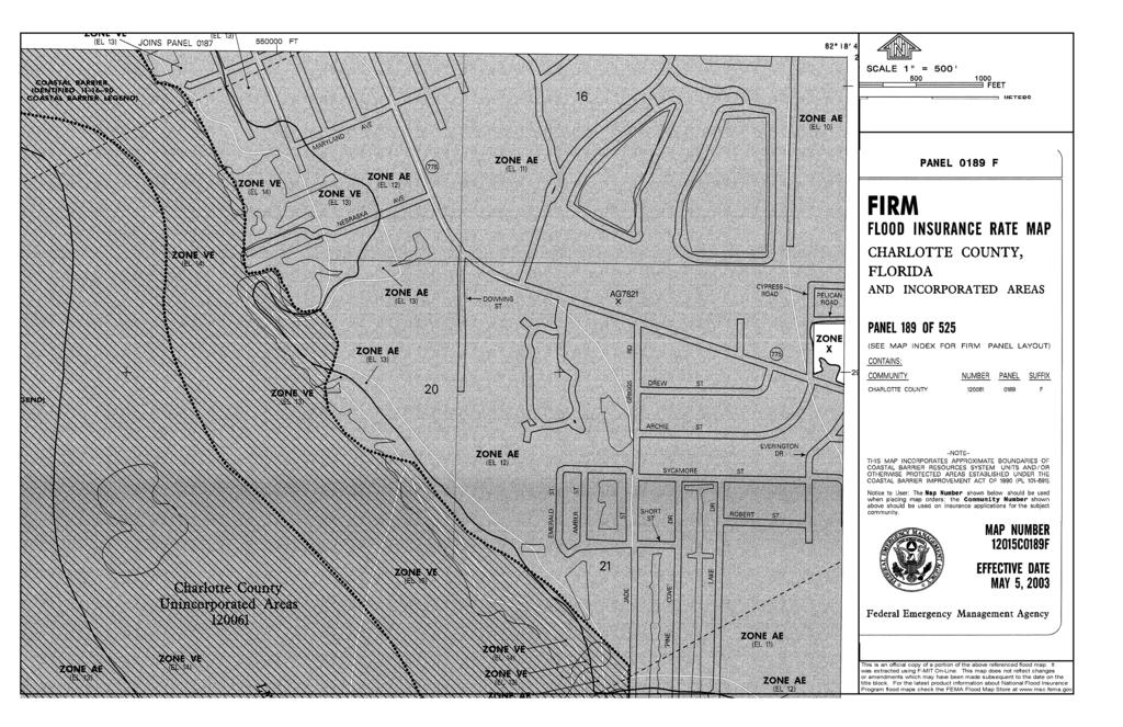
5 GENERAL SITE INFORMATION 1.1 PROJECT LOCATION The Island Lake Estates is a proposed residential community located in Section 16, Township 41 South, and Range 20 East in Charlotte County, Florida. The Tax Parcel Identification for this project is The total area owned for this project amounts to 170 acres, more or less, with approximately 155 acres designated as drainage basin area for the purposes of stormwater calculations. 1.2 PRE-DEVELOPMENT DRAINAGE This project site has been previously permitted in the past. On June 23, 1992 MSSW was issued to Steak & Stone and has since expired. Ajax Paving Industries also obtained WUP 9283, that permit has since been cancelled/inactive. Under MSSW , stormwater pond construction was started. Some of those ponds were permitted with 100yr retention in mind. It also appears that there may have been mining operations on the site prior to construction of MSSW starting. Currently with a portion of the site being excavated and filled under MSSW , the majority of the site flows to the north and northwest with a final destination being Oyster Creek. 1.3 POST-DEVELOPMENT DRAINAGE The proposed project will use a system of drainage collection and conveyance to transport the onsite flows to the proposed stormwater ponds. These onsite stormwater ponds will all be designed to contain the 100yr storm. 1.4 SOILS Based on a review of the National Resources Conservation Service (NRCS) soil survey, the existing site contains 14.9 acres of Myakka Fine Sand, 4 acres of Felda Fine Sand, 46.2 acres of Immokalee Sand, 60.3 acres of Punta Fine Sand, 1.9 acres of Anclote Sand and 4.8 acres of Smyrna Fine Sand, HSG Type B/D. For additional information regarding soil types, please refer to the attached site soils exhibit. 1.5 WATER TABLE The estimated water table for each of the stormwater basins has been based on wetland indicators determined by Earthbalance Environmental firm. Please see plan set for any additional information related to estimated water tables. 1.6 RECEIVING WATERBODY This project proposes to retain all storm events up to and including the 100yr storm. Once the project has reached the 100yr storm event it will be routed to the slough that runs along the eastern boundary of the property. Once in the slough, the water will be received in Oyster Creek (WBID 2067) and Buck Creek (WBID 2068) with final destination of Lemon Bay (WBID 2072). REVISED: 1/29/ _SWM_RPT.DOCX Island Lakes Estates JOB: 3891
6 1.7 EXISTING LAND USE AND COVER Currently the site is undeveloped other than a few of the stormwater ponds that were constructed under MSSW The current land cover is a mixture of upland forest, wetlands, and water. The majority of the site however is covered with upland forest. 1.8 PROPOSED LAND USE AND COVER The proposed project is to develop approximately 170 ac into a residential development. This development will include 294 single family residences along with 106 multi-family units. The project will be served by acres of roads throughout the development. Along with the roads, approximately 42 acres will be dedicated to pervious surfaces. The project will also include 8 lakes equaling approximately 51 acres for 100yr retention acres of wetlands encroach on to the property in the north. REVISED: 1/29/ _SWM_RPT.DOCX Island Lakes Estates JOB: 3891
7 SECTION 2 WATER QUALITY
8 WATER QUALITY 2.1 TREATMENT METHODOLOGY The Southwest Florida Water Management District (SWFWMD) requires that wet detention systems treat one inch of runoff from the entire contributing area to the system (stormwater basin area), in accordance with B.O.R. 5.2 (a)(1). Dry detention systems, both on-line and offline, require that projects greater than 100 acres in size shall treat the runoff from the first one inch of runoff, and as an option for projects less than 100 acres, the first half inch of runoff over the stormwater basin area per B.O.R. 5.2.(c) and (d). The wet detention system's treatment volume shall be discharged in no less than 120 hours (5 days) with no more than one-half the total volume being discharged within the first 60 hours (2.5 days). Due to the detention time required for wet detention systems, only that volume which drains below the overflow elevation within 36 hours may be counted as part of the volume required for water quantity storage under Chapter 4. The total treatment volume shall again be available within 72 hours, however, only that volume which can again be available within 36 hours may be counted as part of the volume required for water quantity storage under Chapter 4. Any project which discharges directly to an Outstanding Florida Water (OFW) shall provide a treatment volume equivalent to an additional 50% of the above criteria. 2.2 IMPAIRED WATERBODY CLASSIFICATION This project is located within the Lemon Bay basin, with corresponding waterbody identification (WBID) Based on a review of the published data from the Florida Department of Environmental Protection (FDEP Run Number 49), this project is classified as an impaired water body for mercury and dissolved oxygen. 2.3 WATERBODY CLASS Based on a review of published data from the Florida Department of Environmental Protection (FDEP), the ultimate discharge location for this project, Charlotte Harbor, is classified as a class 3M water body. It should be noted that this project does not discharge directly to a waterbody classified as a conditionally restricted or Outstanding Florida Water (OFW). 2.4 PROPOSED STORMWATER SYSTEM The proposed stormwater management system will consist of a series of lakes and structures to provide water quality and quantity for the proposed site. These lakes and structures will make up three different basins of varying control elevations. While the site consists of three different basins, of varying control elevations, they all fall within a tidal flood zone with an elevation of 11 NGVD 88. In order to effectively provide the necessary treatment needed for the site and the surrounding waterbodies, 100yr retention will be utilized. REVISED: 1/29/ _SWM_RPT.DOCX Island Lakes Estates JOB: 3891
9 SECTION 3 WATER QUANTITY
10 WATER QUANTITY 3.1 DESIGN CRITERIA The site proposes to attenuate the 100yr storm event. All the necessary storage for will be held within the lake system proposed on site. REVISED: 1/29/ _SWM_RPT.DOCX Island Lakes Estates JOB: 3891
11 SECTION 4 FLOODPLAIN ANALYSIS
12 FLOODPLAIN ANALYSIS 4.1 FLOODPLAIN LOCATION Based on a review of the Federal Emergency Management Agency (FEMA) published floodplain data, this project is located within the boundary of FEMA Panel No C0187F and 12015C0189F dated May 5, This project is located within flood zone AE. AE areas located within zone AE are within the floodplain, with an established flood elevation of TRAVERSING WORKS There are no traversing works proposed. 4.3 FLOODPLAIN IMPACTS The entire site proposes to attenuate the 100yr storm event, therefore eliminating any possible impact to the 100yr floodplain. REVISED: 1/29/ _SWM_RPT.DOCX Island Lakes Estates JOB: 3891
13 SECTION 5 POST DEVELOPMENT ICPR ROUTINGS
14 Network Diagram Nodes A Stage/Area V Stage/Volume T Time/Stage M Manhole A:Basin 3C U:Basin 3C Basins O Overland Flow U SCS Unit CN S SBUH CN Y SCS Unit GA Z SBUH GA Links P Pipe W Weir C Channel D Drop Structure B Bridge R Rating Curve H Breach E Percolation F Filter X Exfil Trench A:Basin 1D U:Basin 1D P:RCP_3 P:RCP A:Basin 3B U:Basin 3B P:RCP_2 A:Basin 3A U:Basin 3A A:Basin 2 A:Basin 1C U:Basin 2 U:Basin 1C P:RCP_4 A:Basin 1B U:Basin 1B P:RCP_5 A:Basin 1A U:Basin 1A Interconnected Channel and Pond Routing Model (ICPR) 2002 Streamline Technologies, Inc.
15 Node Min/Max Max Time Max Warning Max Delta Max Surf Max Time Max Max Time Max Name Group Simulation Stage Stage Stage Stage Area Inflow Inflow Outflow Outflow hrs ft ft ft ft2 hrs cfs hrs cfs Basin 1A BASE 100yr-24hr Basin 1B BASE 100yr-24hr Basin 1C BASE 100yr-24hr Basin 1D BASE 100yr-24hr Basin 2 BASE 100yr-24hr Basin 3A BASE 100yr-24hr Basin 3B BASE 100yr-24hr Basin 3C BASE 100yr-24hr Basin 1A BASE 25yr-24hr Basin 1B BASE 25yr-24hr Basin 1C BASE 25yr-24hr Basin 1D BASE 25yr-24hr Basin 2 BASE 25yr-24hr Basin 3A BASE 25yr-24hr Basin 3B BASE 25yr-24hr Basin 3C BASE 25yr-24hr Basin 1A BASE 5yr-24hr Basin 1B BASE 5yr-24hr Basin 1C BASE 5yr-24hr Basin 1D BASE 5yr-24hr Basin 2 BASE 5yr-24hr Basin 3A BASE 5yr-24hr Basin 3B BASE 5yr-24hr Basin 3C BASE 5yr-24hr Interconnected Channel and Pond Routing Model (ICPR) 2002 Streamline Technologies, Inc. Page 1 of 1
16 Node Min/Max Max Time Max Warning Max Delta Max Surf Max Time Max Max Time Max Name Group Simulation Stage Stage Stage Stage Area Inflow Inflow Outflow Outflow hrs ft ft ft ft2 hrs cfs hrs cfs Basin 1A BASE 100yr-24hr Basin 1B BASE 100yr-24hr Basin 1C BASE 100yr-24hr Basin 1D BASE 100yr-24hr Basin 2 BASE 100yr-24hr Basin 3A BASE 100yr-24hr Basin 3B BASE 100yr-24hr Basin 3C BASE 100yr-24hr Basin 1A BASE 25yr-24hr Basin 1B BASE 25yr-24hr Basin 1C BASE 25yr-24hr Basin 1D BASE 25yr-24hr Basin 2 BASE 25yr-24hr Basin 3A BASE 25yr-24hr Basin 3B BASE 25yr-24hr Basin 3C BASE 25yr-24hr Basin 1A BASE 5yr-24hr Basin 1B BASE 5yr-24hr Basin 1C BASE 5yr-24hr Basin 1D BASE 5yr-24hr Basin 2 BASE 5yr-24hr Basin 3A BASE 5yr-24hr Basin 3B BASE 5yr-24hr Basin 3C BASE 5yr-24hr Interconnected Channel and Pond Routing Model (ICPR) 2002 Streamline Technologies, Inc. Page 1 of 1
17 Input ========================================================================================== ==== Basins ============================================================================== ========================================================================================== Name: Basin 1A Node: Basin 1A Status: Onsite Group: BASE Type: SCS Unit Hydrograph CN Unit Hydrograph: Uh256 Peaking Factor: Rainfall File: Storm Duration(hrs): 0.00 Rainfall Amount(in): Time of Conc(min): Area(ac): Time Shift(hrs): 0.00 Curve Number: Max Allowable Q(cfs): DCIA(%): 0.00 Name: Basin 1B Node: Basin 1B Status: Onsite Group: BASE Type: SCS Unit Hydrograph CN Unit Hydrograph: Uh256 Peaking Factor: Rainfall File: Storm Duration(hrs): 0.00 Rainfall Amount(in): Time of Conc(min): Area(ac): Time Shift(hrs): 0.00 Curve Number: Max Allowable Q(cfs): DCIA(%): 0.00 Name: Basin 1C Node: Basin 1C Status: Onsite Group: BASE Type: SCS Unit Hydrograph CN Unit Hydrograph: Uh256 Peaking Factor: Rainfall File: Storm Duration(hrs): 0.00 Rainfall Amount(in): Time of Conc(min): Area(ac): Time Shift(hrs): 0.00 Curve Number: Max Allowable Q(cfs): DCIA(%): 0.00 Name: Basin 1D Node: Basin 1D Status: Onsite Group: BASE Type: SCS Unit Hydrograph CN Unit Hydrograph: Uh256 Peaking Factor: Rainfall File: Storm Duration(hrs): 0.00 Rainfall Amount(in): Time of Conc(min): Area(ac): Time Shift(hrs): 0.00 Curve Number: Max Allowable Q(cfs): DCIA(%): 0.00 Name: Basin 2 Node: Basin 2 Status: Onsite Group: BASE Type: SCS Unit Hydrograph CN Unit Hydrograph: Uh256 Peaking Factor: Rainfall File: Storm Duration(hrs): 0.00 Rainfall Amount(in): Time of Conc(min): Area(ac): Time Shift(hrs): 0.00 Curve Number: Max Allowable Q(cfs): DCIA(%): 0.00 Name: Basin 3A Node: Basin 3A Status: Onsite Group: BASE Type: SCS Unit Hydrograph CN Unit Hydrograph: Uh256 Peaking Factor: Rainfall File: Storm Duration(hrs): 0.00 Rainfall Amount(in): Time of Conc(min): Area(ac): Time Shift(hrs): 0.00 Curve Number: Max Allowable Q(cfs): DCIA(%): 0.00 Name: Basin 3B Node: Basin 3B Status: Onsite Group: BASE Type: SCS Unit Hydrograph CN Unit Hydrograph: Uh256 Peaking Factor: Rainfall File: Storm Duration(hrs): 0.00 Rainfall Amount(in): Time of Conc(min): Interconnected Channel and Pond Routing Model (ICPR) 2002 Streamline Technologies, Inc. Page 1 of 6
18 Input Area(ac): Time Shift(hrs): 0.00 Curve Number: Max Allowable Q(cfs): DCIA(%): 0.00 Name: Basin 3C Node: Basin 3C Status: Onsite Group: BASE Type: SCS Unit Hydrograph CN Unit Hydrograph: Uh256 Peaking Factor: Rainfall File: Storm Duration(hrs): 0.00 Rainfall Amount(in): Time of Conc(min): Area(ac): Time Shift(hrs): 0.00 Curve Number: Max Allowable Q(cfs): DCIA(%): 0.00 ========================================================================================== ==== Nodes =============================================================================== ========================================================================================== Name: Basin 1A Base Flow(cfs): Init Stage(ft): Group: BASE Warn Stage(ft): Type: Stage/Area Stage(ft) Area(ac) Name: Basin 1B Base Flow(cfs): Init Stage(ft): Group: BASE Warn Stage(ft): Type: Stage/Area Stage(ft) Area(ac) Name: Basin 1C Base Flow(cfs): Init Stage(ft): Group: BASE Warn Stage(ft): Type: Stage/Area Stage(ft) Area(ac) Name: Basin 1D Base Flow(cfs): Init Stage(ft): Group: BASE Warn Stage(ft): Type: Stage/Area Stage(ft) Area(ac) Interconnected Channel and Pond Routing Model (ICPR) 2002 Streamline Technologies, Inc. Page 2 of 6
19 Input Name: Basin 2 Base Flow(cfs): Init Stage(ft): Group: BASE Warn Stage(ft): Type: Stage/Area Stage(ft) Area(ac) Name: Basin 3A Base Flow(cfs): Init Stage(ft): Group: BASE Warn Stage(ft): Type: Stage/Area Stage(ft) Area(ac) Name: Basin 3B Base Flow(cfs): Init Stage(ft): Group: BASE Warn Stage(ft): Type: Stage/Area Stage(ft) Area(ac) Name: Basin 3C Base Flow(cfs): Init Stage(ft): Group: BASE Warn Stage(ft): Type: Stage/Area Stage(ft) Area(ac) ========================================================================================== ==== Pipes =============================================================================== ========================================================================================== Name: From Node: Length(ft): 0.00 Group: BASE To Node: Count: 1 Friction Equation: Average Conveyance UPSTREAM DOWNSTREAM Solution Algorithm: Automatic Geometry: Circular Circular Flow: Both Span(in): Entrance Loss Coef: 0.00 Rise(in): Exit Loss Coef: 0.00 Invert(ft): Bend Loss Coef: 0.00 Manning's N: Outlet Ctrl Spec: Use dc or tw Top Clip(in): Inlet Ctrl Spec: Use dn Bot Clip(in): Stabilizer Option: None Upstream FHWA Inlet Edge Description: Circular CMP: Projecting Interconnected Channel and Pond Routing Model (ICPR) 2002 Streamline Technologies, Inc. Page 3 of 6
20 Input Downstream FHWA Inlet Edge Description: Circular CMP: Projecting Name: RCP From Node: Basin 3B Length(ft): Group: BASE To Node: Basin 3C Count: 1 Friction Equation: Automatic UPSTREAM DOWNSTREAM Solution Algorithm: Most Restrictive Geometry: Circular Circular Flow: Both Span(in): Entrance Loss Coef: 0.00 Rise(in): Exit Loss Coef: 1.00 Invert(ft): Bend Loss Coef: 0.00 Manning's N: Outlet Ctrl Spec: Use dc or tw Top Clip(in): Inlet Ctrl Spec: Use dc Bot Clip(in): Stabilizer Option: None Upstream FHWA Inlet Edge Description: Circular Concrete: Square edge w/ headwall Downstream FHWA Inlet Edge Description: Circular Concrete: Square edge w/ headwall Name: RCP_2 From Node: Basin 3A Length(ft): Group: BASE To Node: Basin 3B Count: 1 Friction Equation: Automatic UPSTREAM DOWNSTREAM Solution Algorithm: Most Restrictive Geometry: Circular Circular Flow: Both Span(in): Entrance Loss Coef: 0.00 Rise(in): Exit Loss Coef: 1.00 Invert(ft): Bend Loss Coef: 0.00 Manning's N: Outlet Ctrl Spec: Use dc or tw Top Clip(in): Inlet Ctrl Spec: Use dc Bot Clip(in): Stabilizer Option: None Upstream FHWA Inlet Edge Description: Circular Concrete: Square edge w/ headwall Downstream FHWA Inlet Edge Description: Circular Concrete: Square edge w/ headwall Name: RCP_3 From Node: Basin 1D Length(ft): Group: BASE To Node: Basin 1C Count: 1 Friction Equation: Automatic UPSTREAM DOWNSTREAM Solution Algorithm: Most Restrictive Geometry: Circular Circular Flow: Both Span(in): Entrance Loss Coef: 0.00 Rise(in): Exit Loss Coef: 1.00 Invert(ft): Bend Loss Coef: 0.00 Manning's N: Outlet Ctrl Spec: Use dc or tw Top Clip(in): Inlet Ctrl Spec: Use dc Bot Clip(in): Stabilizer Option: None Upstream FHWA Inlet Edge Description: Circular Concrete: Square edge w/ headwall Downstream FHWA Inlet Edge Description: Circular Concrete: Square edge w/ headwall Name: RCP_4 From Node: Basin 1B Length(ft): Group: BASE To Node: Basin 1C Count: 1 Friction Equation: Automatic UPSTREAM DOWNSTREAM Solution Algorithm: Most Restrictive Geometry: Circular Circular Flow: Both Span(in): Entrance Loss Coef: 0.00 Rise(in): Exit Loss Coef: 1.00 Invert(ft): Bend Loss Coef: 0.00 Manning's N: Outlet Ctrl Spec: Use dc or tw Top Clip(in): Inlet Ctrl Spec: Use dc Bot Clip(in): Stabilizer Option: None Interconnected Channel and Pond Routing Model (ICPR) 2002 Streamline Technologies, Inc. Page 4 of 6
21 Input Upstream FHWA Inlet Edge Description: Circular Concrete: Square edge w/ headwall Downstream FHWA Inlet Edge Description: Circular Concrete: Square edge w/ headwall Name: RCP_5 From Node: Basin 1A Length(ft): Group: BASE To Node: Basin 1B Count: 1 Friction Equation: Automatic UPSTREAM DOWNSTREAM Solution Algorithm: Most Restrictive Geometry: Circular Circular Flow: Both Span(in): Entrance Loss Coef: 0.00 Rise(in): Exit Loss Coef: 1.00 Invert(ft): Bend Loss Coef: 0.00 Manning's N: Outlet Ctrl Spec: Use dc or tw Top Clip(in): Inlet Ctrl Spec: Use dc Bot Clip(in): Stabilizer Option: None Upstream FHWA Inlet Edge Description: Circular Concrete: Square edge w/ headwall Downstream FHWA Inlet Edge Description: Circular Concrete: Square edge w/ headwall ========================================================================================== ==== Hydrology Simulations =============================================================== ========================================================================================== Name: 100yr-24hr Filename: S:\Jobs\38xx\3891\Engineering\Calculations\SWM\ICPR\100yr-24hr.R32 Override Defaults: Yes Storm Duration(hrs): Rainfall File: Flmod Rainfall Amount(in): Time(hrs) Print Inc(min) Name: 25yr-24hr Filename: S:\Jobs\38xx\3891\Engineering\Calculations\SWM\ICPR\25yr-24hr.R32 Override Defaults: Yes Storm Duration(hrs): Rainfall File: Flmod Rainfall Amount(in): 8.00 Time(hrs) Print Inc(min) Name: 5yr-24hr Filename: S:\Jobs\38xx\3891\Engineering\Calculations\SWM\ICPR\5yr-24hr.R32 Override Defaults: Yes Storm Duration(hrs): Rainfall File: Flmod Rainfall Amount(in): 5.70 Time(hrs) Print Inc(min) ========================================================================================== ==== Routing Simulations ================================================================= ========================================================================================== Name: 100yr-24hr Hydrology Sim: 100yr-24hr Filename: S:\Jobs\38xx\3891\Engineering\Calculations\SWM\ICPR\100yr-24hr.I32 Execute: Yes Restart: No Patch: No Alternative: No Max Delta Z(ft): 1.00 Delta Z Factor: Time Step Optimizer: Start Time(hrs): End Time(hrs): Min Calc Time(sec): Max Calc Time(sec): Boundary Stages: Boundary Flows: Interconnected Channel and Pond Routing Model (ICPR) 2002 Streamline Technologies, Inc. Page 5 of 6
22 Input Time(hrs) Print Inc(min) Group Run BASE Yes Name: 25yr-24hr Hydrology Sim: 25yr-24hr Filename: S:\Jobs\38xx\3891\Engineering\Calculations\SWM\ICPR\25yr-24hr.I32 Execute: Yes Restart: No Patch: No Alternative: No Max Delta Z(ft): 1.00 Delta Z Factor: Time Step Optimizer: Start Time(hrs): End Time(hrs): Min Calc Time(sec): Max Calc Time(sec): Boundary Stages: Boundary Flows: Time(hrs) Print Inc(min) Group Run BASE Yes Name: 5yr-24hr Hydrology Sim: 5yr-24hr Filename: S:\Jobs\38xx\3891\Engineering\Calculations\SWM\ICPR\5yr-24hr.I32 Execute: Yes Restart: No Patch: No Alternative: No Max Delta Z(ft): 1.00 Delta Z Factor: Time Step Optimizer: Start Time(hrs): End Time(hrs): Min Calc Time(sec): Max Calc Time(sec): Boundary Stages: Boundary Flows: Time(hrs) Print Inc(min) Group Run BASE Yes Interconnected Channel and Pond Routing Model (ICPR) 2002 Streamline Technologies, Inc. Page 6 of 6
23 Input ========================================================================================== ==== Basins ============================================================================== ========================================================================================== Name: Basin 1A Node: Basin 1A Status: Onsite Group: BASE Type: SCS Unit Hydrograph CN Unit Hydrograph: Uh256 Peaking Factor: Rainfall File: Storm Duration(hrs): 0.00 Rainfall Amount(in): Time of Conc(min): Area(ac): Time Shift(hrs): 0.00 Curve Number: Max Allowable Q(cfs): DCIA(%): 0.00 Name: Basin 1B Node: Basin 1B Status: Onsite Group: BASE Type: SCS Unit Hydrograph CN Unit Hydrograph: Uh256 Peaking Factor: Rainfall File: Storm Duration(hrs): 0.00 Rainfall Amount(in): Time of Conc(min): Area(ac): Time Shift(hrs): 0.00 Curve Number: Max Allowable Q(cfs): DCIA(%): 0.00 Name: Basin 1C Node: Basin 1C Status: Onsite Group: BASE Type: SCS Unit Hydrograph CN Unit Hydrograph: Uh256 Peaking Factor: Rainfall File: Storm Duration(hrs): 0.00 Rainfall Amount(in): Time of Conc(min): Area(ac): Time Shift(hrs): 0.00 Curve Number: Max Allowable Q(cfs): DCIA(%): 0.00 Name: Basin 1D Node: Basin 1D Status: Onsite Group: BASE Type: SCS Unit Hydrograph CN Unit Hydrograph: Uh256 Peaking Factor: Rainfall File: Storm Duration(hrs): 0.00 Rainfall Amount(in): Time of Conc(min): Area(ac): Time Shift(hrs): 0.00 Curve Number: Max Allowable Q(cfs): DCIA(%): 0.00 Name: Basin 2 Node: Basin 2 Status: Onsite Group: BASE Type: SCS Unit Hydrograph CN Unit Hydrograph: Uh256 Peaking Factor: Rainfall File: Storm Duration(hrs): 0.00 Rainfall Amount(in): Time of Conc(min): Area(ac): Time Shift(hrs): 0.00 Curve Number: Max Allowable Q(cfs): DCIA(%): 0.00 Name: Basin 3A Node: Basin 3A Status: Onsite Group: BASE Type: SCS Unit Hydrograph CN Unit Hydrograph: Uh256 Peaking Factor: Rainfall File: Storm Duration(hrs): 0.00 Rainfall Amount(in): Time of Conc(min): Area(ac): Time Shift(hrs): 0.00 Curve Number: Max Allowable Q(cfs): DCIA(%): 0.00 Name: Basin 3B Node: Basin 3B Status: Onsite Group: BASE Type: SCS Unit Hydrograph CN Unit Hydrograph: Uh256 Peaking Factor: Rainfall File: Storm Duration(hrs): 0.00 Rainfall Amount(in): Time of Conc(min): Interconnected Channel and Pond Routing Model (ICPR) 2002 Streamline Technologies, Inc. Page 1 of 6
24 Input Area(ac): Time Shift(hrs): 0.00 Curve Number: Max Allowable Q(cfs): DCIA(%): 0.00 Name: Basin 3C Node: Basin 3C Status: Onsite Group: BASE Type: SCS Unit Hydrograph CN Unit Hydrograph: Uh256 Peaking Factor: Rainfall File: Storm Duration(hrs): 0.00 Rainfall Amount(in): Time of Conc(min): Area(ac): Time Shift(hrs): 0.00 Curve Number: Max Allowable Q(cfs): DCIA(%): 0.00 ========================================================================================== ==== Nodes =============================================================================== ========================================================================================== Name: Basin 1A Base Flow(cfs): Init Stage(ft): Group: BASE Warn Stage(ft): Type: Stage/Area Stage(ft) Area(ac) Name: Basin 1B Base Flow(cfs): Init Stage(ft): Group: BASE Warn Stage(ft): Type: Stage/Area Stage(ft) Area(ac) Name: Basin 1C Base Flow(cfs): Init Stage(ft): Group: BASE Warn Stage(ft): Type: Stage/Area Stage(ft) Area(ac) Name: Basin 1D Base Flow(cfs): Init Stage(ft): Group: BASE Warn Stage(ft): Type: Stage/Area Stage(ft) Area(ac) Interconnected Channel and Pond Routing Model (ICPR) 2002 Streamline Technologies, Inc. Page 2 of 6
25 Input Name: Basin 2 Base Flow(cfs): Init Stage(ft): Group: BASE Warn Stage(ft): Type: Stage/Area Stage(ft) Area(ac) Name: Basin 3A Base Flow(cfs): Init Stage(ft): Group: BASE Warn Stage(ft): Type: Stage/Area Stage(ft) Area(ac) Name: Basin 3B Base Flow(cfs): Init Stage(ft): Group: BASE Warn Stage(ft): Type: Stage/Area Stage(ft) Area(ac) Name: Basin 3C Base Flow(cfs): Init Stage(ft): Group: BASE Warn Stage(ft): Type: Stage/Area Stage(ft) Area(ac) ========================================================================================== ==== Pipes =============================================================================== ========================================================================================== Name: From Node: Length(ft): 0.00 Group: BASE To Node: Count: 1 Friction Equation: Average Conveyance UPSTREAM DOWNSTREAM Solution Algorithm: Automatic Geometry: Circular Circular Flow: Both Span(in): Entrance Loss Coef: 0.00 Rise(in): Exit Loss Coef: 0.00 Invert(ft): Bend Loss Coef: 0.00 Manning's N: Outlet Ctrl Spec: Use dc or tw Top Clip(in): Inlet Ctrl Spec: Use dn Bot Clip(in): Stabilizer Option: None Upstream FHWA Inlet Edge Description: Circular CMP: Projecting Interconnected Channel and Pond Routing Model (ICPR) 2002 Streamline Technologies, Inc. Page 3 of 6
26 Input Downstream FHWA Inlet Edge Description: Circular CMP: Projecting Name: RCP From Node: Basin 3B Length(ft): Group: BASE To Node: Basin 3C Count: 1 Friction Equation: Automatic UPSTREAM DOWNSTREAM Solution Algorithm: Most Restrictive Geometry: Circular Circular Flow: Both Span(in): Entrance Loss Coef: 0.00 Rise(in): Exit Loss Coef: 1.00 Invert(ft): Bend Loss Coef: 0.00 Manning's N: Outlet Ctrl Spec: Use dc or tw Top Clip(in): Inlet Ctrl Spec: Use dc Bot Clip(in): Stabilizer Option: None Upstream FHWA Inlet Edge Description: Circular Concrete: Square edge w/ headwall Downstream FHWA Inlet Edge Description: Circular Concrete: Square edge w/ headwall Name: RCP_2 From Node: Basin 3A Length(ft): Group: BASE To Node: Basin 3B Count: 1 Friction Equation: Automatic UPSTREAM DOWNSTREAM Solution Algorithm: Most Restrictive Geometry: Circular Circular Flow: Both Span(in): Entrance Loss Coef: 0.00 Rise(in): Exit Loss Coef: 1.00 Invert(ft): Bend Loss Coef: 0.00 Manning's N: Outlet Ctrl Spec: Use dc or tw Top Clip(in): Inlet Ctrl Spec: Use dc Bot Clip(in): Stabilizer Option: None Upstream FHWA Inlet Edge Description: Circular Concrete: Square edge w/ headwall Downstream FHWA Inlet Edge Description: Circular Concrete: Square edge w/ headwall Name: RCP_3 From Node: Basin 1D Length(ft): Group: BASE To Node: Basin 1C Count: 1 Friction Equation: Automatic UPSTREAM DOWNSTREAM Solution Algorithm: Most Restrictive Geometry: Circular Circular Flow: Both Span(in): Entrance Loss Coef: 0.00 Rise(in): Exit Loss Coef: 1.00 Invert(ft): Bend Loss Coef: 0.00 Manning's N: Outlet Ctrl Spec: Use dc or tw Top Clip(in): Inlet Ctrl Spec: Use dc Bot Clip(in): Stabilizer Option: None Upstream FHWA Inlet Edge Description: Circular Concrete: Square edge w/ headwall Downstream FHWA Inlet Edge Description: Circular Concrete: Square edge w/ headwall Name: RCP_4 From Node: Basin 1B Length(ft): Group: BASE To Node: Basin 1C Count: 1 Friction Equation: Automatic UPSTREAM DOWNSTREAM Solution Algorithm: Most Restrictive Geometry: Circular Circular Flow: Both Span(in): Entrance Loss Coef: 0.00 Rise(in): Exit Loss Coef: 1.00 Invert(ft): Bend Loss Coef: 0.00 Manning's N: Outlet Ctrl Spec: Use dc or tw Top Clip(in): Inlet Ctrl Spec: Use dc Bot Clip(in): Stabilizer Option: None Interconnected Channel and Pond Routing Model (ICPR) 2002 Streamline Technologies, Inc. Page 4 of 6
27 Input Upstream FHWA Inlet Edge Description: Circular Concrete: Square edge w/ headwall Downstream FHWA Inlet Edge Description: Circular Concrete: Square edge w/ headwall Name: RCP_5 From Node: Basin 1A Length(ft): Group: BASE To Node: Basin 1B Count: 1 Friction Equation: Automatic UPSTREAM DOWNSTREAM Solution Algorithm: Most Restrictive Geometry: Circular Circular Flow: Both Span(in): Entrance Loss Coef: 0.00 Rise(in): Exit Loss Coef: 1.00 Invert(ft): Bend Loss Coef: 0.00 Manning's N: Outlet Ctrl Spec: Use dc or tw Top Clip(in): Inlet Ctrl Spec: Use dc Bot Clip(in): Stabilizer Option: None Upstream FHWA Inlet Edge Description: Circular Concrete: Square edge w/ headwall Downstream FHWA Inlet Edge Description: Circular Concrete: Square edge w/ headwall ========================================================================================== ==== Hydrology Simulations =============================================================== ========================================================================================== Name: 100yr-24hr Filename: S:\Jobs\38xx\3891\Engineering\Calculations\SWM\ICPR\100yr-24hr.R32 Override Defaults: Yes Storm Duration(hrs): Rainfall File: Flmod Rainfall Amount(in): Time(hrs) Print Inc(min) Name: 25yr-24hr Filename: S:\Jobs\38xx\3891\Engineering\Calculations\SWM\ICPR\25yr-24hr.R32 Override Defaults: Yes Storm Duration(hrs): Rainfall File: Flmod Rainfall Amount(in): 8.00 Time(hrs) Print Inc(min) Name: 5yr-24hr Filename: S:\Jobs\38xx\3891\Engineering\Calculations\SWM\ICPR\5yr-24hr.R32 Override Defaults: Yes Storm Duration(hrs): Rainfall File: Flmod Rainfall Amount(in): 5.70 Time(hrs) Print Inc(min) ========================================================================================== ==== Routing Simulations ================================================================= ========================================================================================== Name: 100yr-24hr Hydrology Sim: 100yr-24hr Filename: S:\Jobs\38xx\3891\Engineering\Calculations\SWM\ICPR\100yr-24hr.I32 Execute: Yes Restart: No Patch: No Alternative: No Max Delta Z(ft): 1.00 Delta Z Factor: Time Step Optimizer: Start Time(hrs): End Time(hrs): Min Calc Time(sec): Max Calc Time(sec): Boundary Stages: Boundary Flows: Interconnected Channel and Pond Routing Model (ICPR) 2002 Streamline Technologies, Inc. Page 5 of 6
28 Input Time(hrs) Print Inc(min) Group Run BASE Yes Name: 25yr-24hr Hydrology Sim: 25yr-24hr Filename: S:\Jobs\38xx\3891\Engineering\Calculations\SWM\ICPR\25yr-24hr.I32 Execute: Yes Restart: No Patch: No Alternative: No Max Delta Z(ft): 1.00 Delta Z Factor: Time Step Optimizer: Start Time(hrs): End Time(hrs): Min Calc Time(sec): Max Calc Time(sec): Boundary Stages: Boundary Flows: Time(hrs) Print Inc(min) Group Run BASE Yes Name: 5yr-24hr Hydrology Sim: 5yr-24hr Filename: S:\Jobs\38xx\3891\Engineering\Calculations\SWM\ICPR\5yr-24hr.I32 Execute: Yes Restart: No Patch: No Alternative: No Max Delta Z(ft): 1.00 Delta Z Factor: Time Step Optimizer: Start Time(hrs): End Time(hrs): Min Calc Time(sec): Max Calc Time(sec): Boundary Stages: Boundary Flows: Time(hrs) Print Inc(min) Group Run BASE Yes Interconnected Channel and Pond Routing Model (ICPR) 2002 Streamline Technologies, Inc. Page 6 of 6
29 Blue Numbers Red Numbers = Input data = Answers Curve Number Calculation Basin Area = 4.65 ac. Total Imperious Area = 1.21 ac. Impervious CN = 98 Pond/Wetland Area = 0.54 ac. Pond/Wetland CN = 100 Pervious Area (1) = 1.68 ac. Pervious CN (1) = 80 Pervious Area (2) = 1.22 ac. Pervious CN (2) = 80 Weighted Curve Number = 87.0
30 Blue Numbers Red Numbers = Input data = Answers Curve Number Calculation Basin Area = 6.96 ac. Total Imperious Area = 1.30 ac. Impervious CN = 98 Pond/Wetland Area = 2.64 ac. Pond/Wetland CN = 100 Pervious Area (1) = 1.77 ac. Pervious CN (1) = 80 Pervious Area (2) = 1.25 ac. Pervious CN (2) = 80 Weighted Curve Number = 91.0
31 Blue Numbers Red Numbers = Input data = Answers Curve Number Calculation Basin Area = ac. Total Imperious Area = 2.93 ac. Impervious CN = 98 Pond/Wetland Area = 3.12 ac. Pond/Wetland CN = 100 Pervious Area (1) = 3.77 ac. Pervious CN (1) = 80 Pervious Area (2) = 3.04 ac. Pervious CN (2) = 80 Weighted Curve Number = 89.0
32 Blue Numbers Red Numbers = Input data = Answers Curve Number Calculation Basin Area = ac. Total Imperious Area = 6.16 ac. Impervious CN = 98 Pond/Wetland Area = 9.92 ac. Pond/Wetland CN = 100 Pervious Area (1) = 8.37 ac. Pervious CN (1) = 80 Pervious Area (2) = 3.25 ac. Pervious CN (2) = 80 Weighted Curve Number = 91.2
33 Blue Numbers Red Numbers = Input data = Answers Curve Number Calculation Basin Area = ac. Total Imperious Area = 2.90 ac. Impervious CN = 98 Pond/Wetland Area = 1.68 ac. Pond/Wetland CN = 100 Pervious Area (1) = 3.44 ac. Pervious CN (1) = 80 Pervious Area (2) = 3.36 ac. Pervious CN (2) = 80 Weighted Curve Number = 87.5
34 Blue Numbers Red Numbers = Input data = Answers Curve Number Calculation Basin Area = ac. Total Imperious Area = 6.08 ac. Impervious CN = 98 Pond/Wetland Area = ac. Pond/Wetland CN = 100 Pervious Area (1) = 7.45 ac. Pervious CN (1) = 80 Pervious Area (2) = ac. Pervious CN (2) = 80 Weighted Curve Number = 89.6
35 Blue Numbers Red Numbers = Input data = Answers Curve Number Calculation Basin Area = ac. Total Imperious Area = 4.18 ac. Impervious CN = 98 Pond/Wetland Area = 7.49 ac. Pond/Wetland CN = 100 Pervious Area (1) = 5.01 ac. Pervious CN (1) = 80 Pervious Area (2) = 3.55 ac. Pervious CN (2) = 80 Weighted Curve Number = 91.1
36 Blue Numbers Red Numbers = Input data = Answers Curve Number Calculation Basin Area = ac. Total Imperious Area = 8.08 ac. Impervious CN = 98 Pond/Wetland Area = ac. Pond/Wetland CN = 100 Pervious Area (1) = ac. Pervious CN (1) = 80 Pervious Area (2) = 4.12 ac. Pervious CN (2) = 0 Weighted Curve Number = 82.3

37 SECTION 6 EXHIBITS REVISED: 1/29/ _SWM_RPT.DOCX Island Lakes Estates JOB: 3891

38 82 19' 19'' W Soil Map Charlotte County, Florida (ISLAND LAKE ESTATES) 82 18' 44'' W ' 51'' N ' 51'' N 26 53' 59'' N ' 59'' N 82 19' 19'' W N Map Scale: 1:4,470 if printed on B portrait (11" x 17") sheet. Meters Feet Map projection: Web Mercator Corner coordinates: WGS84 Edge tics: UTM Zone 17N WGS ' 44'' W Natural Resources Conservation Service Web Soil Survey National Cooperative Soil Survey 10/13/2014 Page 1 of 3
39 Soil Map Charlotte County, Florida (ISLAND LAKE ESTATES) MAP LEGEND MAP INFORMATION Area of Interest (AOI) Area of Interest (AOI) Soils Soil Map Unit Polygons Soil Map Unit Lines Soil Map Unit Points Special Point Features Blowout Borrow Pit Clay Spot Closed Depression Gravel Pit Gravelly Spot Landfill Lava Flow Marsh or swamp Mine or Quarry Miscellaneous Water Perennial Water Rock Outcrop Saline Spot Sandy Spot Severely Eroded Spot Sinkhole Slide or Slip Sodic Spot Spoil Area Stony Spot Very Stony Spot Wet Spot Other Special Line Features Water Features Streams and Canals Transportation Rails Interstate Highways US Routes Major Roads Local Roads Background Aerial Photography The soil surveys that comprise your AOI were mapped at 1:20,000. Warning: Soil Map may not be valid at this scale. Enlargement of maps beyond the scale of mapping can cause misunderstanding of the detail of mapping and accuracy of soil line placement. The maps do not show the small areas of contrasting soils that could have been shown at a more detailed scale. Please rely on the bar scale on each map sheet for map measurements. Source of Map: Natural Resources Conservation Service Web Soil Survey URL: Coordinate System: Web Mercator (EPSG:3857) Maps from the Web Soil Survey are based on the Web Mercator projection, which preserves direction and shape but distorts distance and area. A projection that preserves area, such as the Albers equal-area conic projection, should be used if more accurate calculations of distance or area are required. This product is generated from the USDA-NRCS certified data as of the version date(s) listed below. Soil Survey Area: Charlotte County, Florida Survey Area Data: Version 11, Sep 9, 2014 Soil map units are labeled (as space allows) for map scales 1:50,000 or larger. Date(s) aerial images were photographed: 18, 2011 Feb 10, 2010 Mar The orthophoto or other base map on which the soil lines were compiled and digitized probably differs from the background imagery displayed on these maps. As a result, some minor shifting of map unit boundaries may be evident. Natural Resources Conservation Service Web Soil Survey National Cooperative Soil Survey 10/13/2014 Page 2 of 3
40 Soil Map Charlotte County, Florida ISLAND LAKE ESTATES Map Unit Legend Charlotte County, Florida (FL015) Map Unit Symbol Map Unit Name Acres in AOI Percent of AOI 11 Myakka fine sand, 0 to 2 percent slopes 12 Felda fine sand, 0 to 2 percent slopes 28 Immokalee sand, 0 to 2 percent slopes % % % 29 Punta fine sand % 40 Anclote sand, depressional % 43 Smyrna fine sand, 0 to 2 percent slopes % 99 Water % Totals for Area of Interest % Natural Resources Conservation Service Web Soil Survey National Cooperative Soil Survey 10/13/2014 Page 3 of 3
41
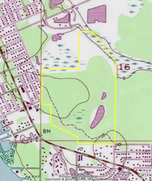
42 3891_USGS
Interconnected Channel and Pond Routing Model (ICPR) 2002 Streamline Technologies, Inc. Page 1 of 5
 2002 Streamline Technologies, Inc. Page 1 of 5") ==== Basins ============================================================================== Name: 1A Node: Swale 1 Status: Onsite : Type: SCS Unit Hydrograph CN Unit Hydrograph: Uh256 Peaking Factor: 256.0
==== Basins ============================================================================== Name: 1A Node: Swale 1 Status: Onsite : Type: SCS Unit Hydrograph CN Unit Hydrograph: Uh256 Peaking Factor: 256.0
Custom Soil Resource Report. Soil Map. Map projection: Web Mercator Corner coordinates: WGS84 Edge tics: UTM Zone 14N WGS84. Feet.
 Custom Soil Resource Report Soil Map 3188500 3188700 3188900 3189100 3189300 3189500 3189700 96 43' 30'' W 3188500 3188700 3188900 3189100 3189300 3189500 3189700 96 42' 11'' W 28 48' 59'' N 28 48' 59''
Custom Soil Resource Report for Victoria County, Texas
 United States Department of Agriculture Natural Resources Conservation Service A product of the National Cooperative Soil Survey, a joint effort of the United States Department of Agriculture and other
Wal-mart Store # Ft. Walton Beach, FL NE Corner of Eglin Parkway/S.R. 85 and South Street STORMWATER REPORT. February 2017
 Wal-mart Store #6746-00 Ft. Walton Beach, FL NE Corner of Eglin Parkway/S.R. 85 and South Street STORMWATER REPORT February 2017 CPH Project No. W13900 1031-C W. 23rd Street Panama City, FL 32405 Phone
T his map is for illus trative purpos es only and does not repres ent a s urvey. I t is provided 'as is ' without warranty or any repres entation of
 http://montgomerytx.mygisonline.com/print/?extent=2988061.71355584,14087737.6935746,299... 3/2/2017 10:41 AM 20 Montgomery CAD, TX Date Printed: 3 /2 /2017 T his map is for illus trative purpos es only
Soil Map Boulder County Area, Colorado (Planet Blue Grass) Web Soil Survey National Cooperative Soil Survey
 Web Soil Survey National Cooperative Soil Survey") 475910 476000 476090 476180 476270 476360 105 16' 21'' W 476450 476540 476630 476720 476810 4453350 4453440 4453260 4453350 4453170 4453260 4453080 4453170 4453080 475820 475910 4452990 476000 476090 476180
475910 476000 476090 476180 476270 476360 105 16' 21'' W 476450 476540 476630 476720 476810 4453350 4453440 4453260 4453350 4453170 4453260 4453080 4453170 4453080 475820 475910 4452990 476000 476090 476180
BUNCOMBE COUNTY NORTH CAROLINA
 PROJECT SITE ² 0 0. 75 1. 5 LOCATION MAP MARCH 2018 2. 25 3 Mil es AID: PROJECT # 2018-01122 18.05301 Sheet 1 of 7 Sources: Esri, HERE, DeLorme, USGS, Intermap, INCREMENT P, NRCan, Esri Japan, METI, Esri
CRUM RANCH AREA MAP YOLO COUNTY, California, AC +/-
 CRUM RANCH AREA MAP YOLO COUNTY, California, 235.59 AC +/- Map data 2016 Google Imagery 2016, CAPCOG, DigitalGlobe, Texas Orthoimagery Program, U.S. Geological Survey, USDA Farm Service Agency Boundary
Submitted to: St. Johns River Power Park New Berlin Road Jacksonville, FL 32226
 RUN-ON/RUN-OFF CONTROL SYSTEM PLAN RUN-ON AND RUN-OFF CONTROL SYSTEM PLAN St. Johns River Power Park Byproduct Storage Area B Phase I Development Submitted to: St. Johns River Power Park 11201 New Berlin
Custom Soil Resource Report Soil Map
 78 10' 44'' W Custom Soil Resource Report Soil Map 78 9' 40'' W 40 37' 18'' N 738700 738800 738900 739000 739100 739200 739300 739400 739500 739600 739700 739800 739900 740000 740100 40 37' 18'' N 4499700
RANCHO de DOS PALMAS DAVIS, California, AC +/-
 RANCHO de DOS PALMAS DAVIS, California, 507.28 AC +/- Boundary Transmission Line Pond / Tank Well SCOTT STONE P: (530) 662-4094 sastone57@gmail.com 37874 County Road 28, Woodland, Ca. 95695 The information
CALIFORNIA AGRICULTURAL PR OPERTIES, IN C. GALE RANCH
 CALIFORNIA AGRICULTURAL PR OPERTIES, IN C. GALE RANCH LOCATION: The Ranch is located 6 Yi miles west of the City of Davis on the northwest corner of County Roads 29A and 92E in Yolo County. SIZE: 368.64
Westshore Marina District Bridge Street Phase 2 (f.k.a. New Port Tampa Bay Phase 2) Stormwater Management Plan & Report
 Stormwater Management Plan & Report") Westshore Marina District Bridge Street Phase 2 (f.k.a. New Port Tampa Bay Phase 2) Stormwater Management Plan & Report Prepared for BTI Partners 401 E. Las Olas Blvd, Suite 1870 Fort Lauderdale, FL 33301
Westshore Marina District Bridge Street Phase 2 (f.k.a. New Port Tampa Bay Phase 2) Stormwater Management Plan & Report Prepared for BTI Partners 401 E. Las Olas Blvd, Suite 1870 Fort Lauderdale, FL 33301
FOR SALE. Features Rives Road Petersburg, Virginia Chris Jenkins
 FOR SALE 3513 Rives Road Petersburg, Virginia 23805 Chris Jenkins T 804-228-4928 E cjenkins@ commonwealthcommercial.com Bill Barnett T 804-433-1821 E bbarnett@ commonwealthcommercial.com Features 142±
DRAINAGE REPORT FOR ROCKY S CONVENIENCE STORE
 HYDRA ENGINEERING AND CONSTRUCTION, LLC C.A. #28124 DRAINAGE REPORT FOR ROCKY S CONVENIENCE STORE Wakulla County, Florida August 8, 2016 PREPARED FOR: The North West Florida Water Management District Hydra
Custom Soil Resource Report for Forrest County, Mississippi
 United States Department of Agriculture Natural Resources Conservation Service A product of the National Cooperative Soil Survey, a joint effort of the United States Department of Agriculture and other
Exhibit RMP-4. Foote Creek Geology and Topography
 Exhibit RMP-4 Foote Creek Geology and Topography Memorandum To: From: CC: Travis Brown, PacifiCorp Daria Drago, P.E., PMP Dr. Deb Luchsinger Date: January 9, 2019 Re: Foote Creek Rim 1 - Geologic Conditions
Custom Soil Resource Report Soil Map
 121 3' 56'' W Custom Soil Resource Report Soil Map 121 2' 49'' W 45 16' 39'' N 5013800 5014000 5014200 5014400 5014600 5014800 5015000 5015200 5015400 5015600 651800 652000 652200 652400 652600 652800
Stormwater Management Engineering Report
 March 12, 2018 Stormwater Management Engineering Report for Brighton Oaks Subdivision Cato Road Bay County, Florida Prepared for: DR Horton PO Box 958 Lynn Haven, Florida, 32444 Ph. 850.265.6979 Fax. 850.265.9942
Soil Map Polk County, Florida
 Soil Map Polk County, Florida 28 9' 21'' 28 8' 23'' 3113000 3113200 3113400 3113600 3113800 3114000 3114200 3114400 3114600 81 51' 19'' 81 51' 19'' 416000 416000 ± 416200 416200 68 416400 68 416400 7 13
PARADIGM ODP FORT COLLINS, CO 80525
 DRAINAGE REPORT PARADIGM ODP FORT COLLINS, CO 80525 Prepared For: Paradigm Properties, LLC 2186 Knoll Drive Ventura, CA 93003 Prepared By Coffey Engineering & Surveying 4045 St. Cloud Drive, Suite 180
BRANDON LAKES AVENUE PRE AND POST CONDITIONS DRAINAGE REPORT
 BRANDON LAKES AVENUE PRE AND POST CONDITIONS DRAINAGE REPORT Hillsborough County Public Works County Center, 22nd Floor 601 E. Kennedy Blvd. Tampa, FL 33602 BRANDON LAKES AVENUE DRAINAGE IMPROVEMENTS Capital
Web Soil Survey National Cooperative Soil Survey
 121 52' 18'' W Irrigated Capability Class Sutter County, California () 121 51' 49'' W 597600 597700 597800 597900 598000 598100 598200 39 6' 27'' N 39 6' 27'' N 39 5' 57'' N 4328400 4328500 4328600 4328700
Hydric Rating by Map Unit Harrison County, Mississippi. Web Soil Survey National Cooperative Soil Survey
 89 9' 7'' W 89 8' 38'' W 30 34' 13'' N 30 33' 57'' N 3383480 3383560 3383640 3383720 3383800 3383880 3383960 293640 293720 293800 293880 293960 294040 294120 294200 294280 294360 3383480 3383560 3383640
Hydric Rating by Map Unit Harrison County, Mississippi
 89 6' 12'' W 89 5' 54'' W 30 28' 47'' N 30 28' 26'' N 3373210 3373290 3373370 3373450 3373530 3373610 3373690 3373770 3373850 298080 298160 298240 298320 298400 298480 298560 30 28' 47'' N Soil Map may
Hydric Rating by Map Unit Ocean County, New Jersey (Larsen & N New Prospect Jackson Twp., NJ)
") 74 16' 14'' W Hydric Rating by Map Unit Ocean County, New Jersey ( ) 74 15' 50'' W 40 9' 17'' N 40 8' 53'' N 4444460 4444550 4444640 4444730 4444820 4444910 4445000 4445090 4445180 562120 562210 562300
74 16' 14'' W Hydric Rating by Map Unit Ocean County, New Jersey ( ) 74 15' 50'' W 40 9' 17'' N 40 8' 53'' N 4444460 4444550 4444640 4444730 4444820 4444910 4445000 4445090 4445180 562120 562210 562300
Aqua Dome Express Car Wash
 Aqua Dome Express Car Wash Stormwater Design Calculations Prepared by: 6997 Professional Parkway East, Suite B Lakewood Ranch, Florida 34240 (941) 444-6644 www.morrisengineering.net Prepared for: Florida
Hartmann Ranch. potential vineyard ground acres +/
 Hartmann Ranch potential vineyard ground 95.403 acres +/ Location: Description: Water: Improvements: Crop history This ranch is located on Jefferson Blvd just South of North Courtland Road a few miles
CALIFORNIA AGRICULTURAL PR OPERTIES, IN C. BOWLSBEY 320 LIBERTY ISLAND ROAD BUYER: RASSMUSSEN TRUST
 CALIFORNIA AGRICULTURAL PR OPERTIES, IN C. BOWLSBEY 320 LIBERTY ISLAND ROAD SELLER: BOWLSBEY TRUST BUYER: RASSMUSSEN TRUST LOCATION: The Bowlsbey 320 is located ten (10) miles southeast of the City of
Using the Web Soil Survey Resilience and Resistance Score Sheet Soils Report
 Using the Resilience and Resistance Score Sheet Soils Report 1. Go to http://websoilsurvey.nrcs.usda.gov/app/ and click on the Start WSS button. 2. Create an Area of Interest (AOI) using any of the available
TRACT 7: ±252 Acres Irrigated Farmland Grassland
 TRACT 7: ±252 Acres Irrigated Farmland Grassland 1880 FM 2013, Friona, Texas 79035 ±252 acres of irrigated farmland and grassland. This farmland is currently being leased and farmed. The lease agreement
Web Soil Survey National Cooperative Soil Survey
 122 14' 27'' W () 122 13' 37'' W 40 8' 40'' N 564700 564800 564900 565000 565100 565200 565300 565400 565500 565600 565700 565800 40 8' 40'' N 4443400 4443500 4443600 4443700 4443800 4443900 4444000 4443400
Web Soil Survey National Cooperative Soil Survey
 252500 252600 252700 252800 252900 253000 253100 83 47' 15'' W 83 47' 49'' W Nonirrigated Capability Class Jackson and Owsley Counties, Kentucky (Peggy Wilson Booneville Property - ) 253200 253300 37 25'
Custom Soil Resource Report for Clackamas County Area, Oregon
 United States Department of Agriculture Natural Resources Conservation Service A product of the National Cooperative Soil Survey, a joint effort of the United States Department of Agriculture and other
Custom Soil Resource Report for Multnomah County Area, Oregon
 United States Department of Agriculture Natural Resources Conservation Service A product of the National Cooperative Soil Survey, a joint effort of the United States Department of Agriculture and other
Custom Soil Resource Report for Clackamas County Area, Oregon
 United States Department of Agriculture Natural Resources Conservation Service A product of the National Cooperative Soil Survey, a joint effort of the United States Department of Agriculture and other
Custom Soil Resource Report for Valley County, Montana
 United States Department of Agriculture Natural Resources Conservation Service A product of the National Cooperative Soil Survey, a joint effort of the United States Department of Agriculture and other
Appendix 2b. NRCS Soil Survey
 Appendix 2b NRCS Soil Survey 118 19' 25'' W Nonirrigated Capability Class Antelope Valley Area, California (Del Sur Solar Site) 118 17' 28'' W 378900 379200 379500 379800 380100 380400 380700 381000 381300
Cripps Ranch 76+/- Acres Orchard Development Opportunity Dixon, CA. Presented By:
 Cripps Ranch 76+/- Acres Orchard Development Opportunity Dixon, CA Presented By: Cripps Ranch 76+/- Acres Orchard Development Opportunity Dixon, CA Location: This property is located at 5663 Dally Road
Wright County, MN. Overview. Legend
 Wright County, MN Overview 461 ft Legend Roads CSAHCL CTYCL MUNICL PRIVATECL TWPCL Highways Interstate State Hwy US Hwy City/Township Limits c t Subdivisions Parcels Water 2' Contours 842; 844; 846; 848;
² 2015 Program Year. Farm Tract McLeod County, Minnesota 1:4, NHEL NHEL
 United States Department of Agriculture McLeod County, Minnesota Farm 5125 #* 2 3.65 NHEL Tract 2762 1 33.19 NHEL ² 2015 Program Year Map Created November 06, 2014 Common Land Unit Cropland Non-cropland
Web Soil Survey National Cooperative Soil Survey
 95 40' 40'' W 95 40' 0'' W 38 44' 27'' N 4290200 4290300 4290400 4290500 4290600 4290700 4290800 4290900 4291000 4291100 4291200 4291300 4291400 267300 267400 267500 267600 267700 267800 267900 268000
Soil Taxonomy Classification Washington County, Florida (Pine Log 631A)
") 85 54' 36'' W Soil Taxonomy Classification Washington County, Florida () 85 53' 22'' W 30 25' 42'' N 30 25' 42'' N 30 24' 17'' N 30 24' 17'' N 85 54' 36'' W N Map Scale: 1:12,700 if printed on A portrait
85 54' 36'' W Soil Taxonomy Classification Washington County, Florida () 85 53' 22'' W 30 25' 42'' N 30 25' 42'' N 30 24' 17'' N 30 24' 17'' N 85 54' 36'' W N Map Scale: 1:12,700 if printed on A portrait
Web Soil Survey National Cooperative Soil Survey
 95 30' 19'' W Soil Taxonomy Classification Franklin County, Kansas 95 29' 28'' W 38 33' 8'' N 281700 281800 281900 282000 282100 282200 282300 282400 282500 282600 282700 282800 282900 38 33' 8'' N 4269300
Soil Taxonomy Classification Jackson County, Florida (Chipola River) Web Soil Survey National Cooperative Soil Survey
 Web Soil Survey National Cooperative Soil Survey") 85 10' 20'' W Soil Taxonomy Classification Jackson County, Florida () 85 9' 8'' W 30 37' 42'' N 30 37' 42'' N 30 37' 2'' N 30 37' 2'' N 85 10' 20'' W N Map Scale: 1:8,740 if printed on A landscape (11"
85 10' 20'' W Soil Taxonomy Classification Jackson County, Florida () 85 9' 8'' W 30 37' 42'' N 30 37' 42'' N 30 37' 2'' N 30 37' 2'' N 85 10' 20'' W N Map Scale: 1:8,740 if printed on A landscape (11"
Soil Taxonomy Classification Osage County, Kansas. Web Soil Survey National Cooperative Soil Survey
 95 45' 5'' W Soil Taxonomy Classification Osage County, Kansas 95 44' 3'' W 260300 260400 260500 260600 260700 260800 260900 261000 261100 261200 261300 261400 261500 261600 261700 38 33' 4'' N 38 32'
LOCATED IN INDIAN RIVER COUNTY PREPARED FOR S.J.R.W.M.D. AND F.W.C.D. DECEMBER, 2003 Updated 2007 Updated May 2014 PREPARED BY
 FELLSMERE WATER CONTROL DISTRICT EAST MASTER DRAINAGE PLAN AND STORMWATER HYDROLOGIC ANALYSIS OF THE GRAVITY DRAINAGE SYSTEM LOCATED BETWEEN THE EAST BOUNDARY, LATERAL U, THE MAIN CANAL, AND DITCH 24 LOCATED
Web Soil Survey National Cooperative Soil Survey
 95 27' 24'' W Soil Taxonomy Classification Franklin County, Kansas 95 26' 23'' W 285800 285900 286000 286100 286200 286300 286400 286500 286600 286700 286800 286900 287000 287100 287200 38 29' 34'' N 38
Hydric Rating by Map Unit Harrison County, Mississippi 30 27' 27'' 30 26' 57''
 Hydric Rating by Map Unit Harrison County, Mississippi 30 27' 27'' 30 26' 57'' 3370400 3370500 3370600 3370700 3370800 3370900 3371000 3371100 3371200 89 2' 40'' 89 2' 41'' 303700 303700 303800 303800
Custom Soil Resource Report for St. Lucie County, Florida
 United States Department of Agriculture Natural Resources Conservation Service A product of the National Cooperative Soil Survey, a joint effort of the United States Department of Agriculture and other
Producing Chandler Walnut Orchard
 AG-LAND Investment Brokers 275 Sale Lane Red Bluff, CA 96080 530-529-4400 Fax 530-527-5042 Producing Chandler Walnut Orchard West Sacramento Avenue - Chico, CA AG-LAND INVESTMENT BROKERS 275 Sale Lane
Carrick Road $798,000
 1955-2020 Carrick Road 165.76± acres Fayette/Scott Counties $798,000 Offered Exclusively By: Zach Davis Principal Broker +1.859.576.8195 www.kirkfarms.com zach@kirkfarms.com Measuring an appx. 165+/- acres,
STORMWATER REPORT FRITO LAY SUBDIVISION NO. 3
 STORMWATER REPORT FRITO LAY SUBDIVISION NO. 3 May 2018 STORMWATER REPORT I. Subdivision Data a. The parcel is adjacent to the existing Frito Lay property in Topeka; and the subject plat application encompasses
Soil Taxonomy Classification Gadsden County, Florida (Imperial Nursery)
") 84 35' 33'' W 84 38' 3'' W Soil Taxonomy Classification Gadsden County, Florida () 30 32' 17'' N 30 32' 17'' N Map Scale: 1:25,700 if printed on A portrait (8.5" x 11") sheet. N 0 350 700 0 1000 2000 4000
84 35' 33'' W 84 38' 3'' W Soil Taxonomy Classification Gadsden County, Florida () 30 32' 17'' N 30 32' 17'' N Map Scale: 1:25,700 if printed on A portrait (8.5" x 11") sheet. N 0 350 700 0 1000 2000 4000
WATER MANAGEMENT REPORT FOR PAGE ESTATES
 WATER MANAGEMENT REPORT FOR PAGE ESTATES SLB Consulting of SW Florida, LLC PO Box 2826 Bonita Springs, FL. 34133 Phone: 239-948-9566 sandra@slbconsult.com C.O.A. # 25395 September 1, 2014 Sandra L. Bottcher
Custom Soil Resource Report for Bell County, Texas
 United States Department of Agriculture Natural Resources Conservation Service A product of the National Cooperative Soil Survey, a joint effort of the United States Department of Agriculture and other
Stormwater Guidelines and Case Studies. CAHILL ASSOCIATES Environmental Consultants West Chester, PA (610)
") Stormwater Guidelines and Case Studies CAHILL ASSOCIATES Environmental Consultants West Chester, PA (610) 696-4150 www.thcahill.com Goals and Challenges for Manual State Stormwater Policy More Widespread
Stormwater Guidelines and Case Studies CAHILL ASSOCIATES Environmental Consultants West Chester, PA (610) 696-4150 www.thcahill.com Goals and Challenges for Manual State Stormwater Policy More Widespread
Continuing Education Course #101 Drainage Design with WinTR-55
 1 of 5 Continuing Education Course #101 Drainage Design with WinTR-55 1. WinTR-55 uses the Kinematic Wave method for calculating storm runoff rates and volumes. 2. According to the Velocity Method, the
Custom Soil Resource Report for Polk County, Oregon
 United States Department of Agriculture Natural Resources Conservation Service A product of the National Cooperative Soil Survey, a joint effort of the United States Department of Agriculture and other
Wetland Delineation. Proposed CVS Pharmacy 9th Street and US Highway 98 (Avenue E) Apalachicola, Franklin County, Florida
 Apalachicola, Franklin County, Florida") Wetland Delineation Proposed CVS Pharmacy 9th Street and US Highway 98 (Avenue E) Apalachicola, Franklin County, Florida August 11, 2016 Terracon Project No. 49167572 Prepared for: Halstead Montgomery,
Wetland Delineation Proposed CVS Pharmacy 9th Street and US Highway 98 (Avenue E) Apalachicola, Franklin County, Florida August 11, 2016 Terracon Project No. 49167572 Prepared for: Halstead Montgomery,
Table of Contents Project Description... 1 Summary of Existing Conditions... 1 Summary of Proposed Conditions... 1 Stormwater Compliance... 2 Collecti
 Table of Contents Project Description... 1 Summary of Existing Conditions... 1 Summary of Proposed Conditions... 1 Stormwater Compliance... 2 Collection... 2 Treatment... 3 Storage... 3 Disposal... 4 Soils...
Custom Soil Resource Report for Kern County, California, Northwestern Part
 United States Department of Agriculture Natural Resources Conservation Service A product of the National Cooperative Soil Survey, a joint effort of the United States Department of Agriculture and other
ARTICLE 5 (PART 2) DETENTION VOLUME EXAMPLE PROBLEMS
 DETENTION VOLUME EXAMPLE PROBLEMS") ARTICLE 5 (PART 2) DETENTION VOLUME EXAMPLE PROBLEMS Example 5.7 Simple (Detention Nomograph) Example 5.8 Offsite and Unrestricted Areas (HEC-HMS) Example 5.9 Ponds in Series w/ Tailwater (HEC-HMS) Example
ARTICLE 5 (PART 2) DETENTION VOLUME EXAMPLE PROBLEMS Example 5.7 Simple (Detention Nomograph) Example 5.8 Offsite and Unrestricted Areas (HEC-HMS) Example 5.9 Ponds in Series w/ Tailwater (HEC-HMS) Example
Custom Soil Resource Report for Missoula County Area, Montana
 United States Department of Agriculture Natural Resources Conservation Service A product of the National Cooperative Soil Survey, a joint effort of the United States Department of Agriculture and other
INFLOW DESIGN FLOOD CONTROL SYSTEM PLAN 40 C.F.R. PART PLANT YATES ASH POND 2 (AP-2) GEORGIA POWER COMPANY
 GEORGIA POWER COMPANY") INFLOW DESIGN FLOOD CONTROL SYSTEM PLAN 40 C.F.R. PART 257.82 PLANT YATES ASH POND 2 (AP-2) GEORGIA POWER COMPANY EPA s Disposal of Coal Combustion Residuals from Electric Utilities Final Rule (40 C.F.R.
INFLOW DESIGN FLOOD CONTROL SYSTEM PLAN 40 C.F.R. PART 257.82 PLANT YATES ASH POND 2 (AP-2) GEORGIA POWER COMPANY EPA s Disposal of Coal Combustion Residuals from Electric Utilities Final Rule (40 C.F.R.
Custom Soil Resource Report for Clackamas County Area, Oregon, and Marion County Area, Oregon
 United States Department of Agriculture Natural Resources Conservation Service A product of the National Cooperative Soil Survey, a joint effort of the United States Department of Agriculture and other
O\.OLSSON \ ASSOC I ATES
 O\.OLSSON \ ASSOC I ATES NRCS Soils Report Larry D. Knox Juniper Hills Private Landing Strip ) OAProject No. 012-1776 760 Horizon Drive, Suite 1021 Grand Junction, CO 815061 TEL 970.263.7800 I FAX 970.263.7456
Custom Soil Resource Report for Island County, Washington
 United States Department of Agriculture Natural Resources Conservation Service A product of the National Cooperative Soil Survey, a joint effort of the United States Department of Agriculture and other
Custom Soil Resource Report for Solano County, California
 United States Department of Agriculture Natural Resources Conservation Service A product of the National Cooperative Soil Survey, a joint effort of the United States Department of Agriculture and other
Project Description. Project Options. End Analysis On... Apr 26, :00:00. Rainfall Details
 Project Description File Name... 323 - Att Pond 3 East PIPES ONLY.SPF Project Options Flow Units... Elevation Type... Hydrology Method... EPA SWMM Infiltration Method... Link Routing Method... Enable Overflow
Custom Soil Resource Report for Columbus County, North Carolina
 United States Department of Agriculture Natural Resources Conservation Service A product of the National Cooperative Soil Survey, a joint effort of the United States Department of Agriculture and other
Custom Soil Resource Report for Palo Verde Area, California
 United States Department of Agriculture Natural Resources Conservation Service A product of the National Cooperative Soil Survey, a joint effort of the United States Department of Agriculture and other
STREUVER FIDELCO CAPPELLI, LLC YONKERS DOWNTOWN DEVELOPMENT PHASE 1. DRAFT ENVIRONMENTAL IMPACT STATEMENT For: PALISADES POINT
 STREUVER FIDELCO CAPPELLI, LLC YONKERS DOWNTOWN DEVELOPMENT PHASE 1 DRAFT ENVIRONMENTAL IMPACT STATEMENT For: PALISADES POINT Prepared by: PAULUS, SOKOLOWSKI & SARTOR STORMWATER MANAGEMENT 1. Methodology
Custom Soil Resource Report for Fresno County, California, Western Part
 United States Department of Agriculture Natural Resources Conservation Service A product of the National Cooperative Soil Survey, a joint effort of the United States Department of Agriculture and other
Aperio Property Consultants, llc E. Grand Ave. Aurora, CO Phone (303) Contact: Aaron Thompson
 Contact: Aaron Thompson") Preliminary Development Plan PD Land Suitability Analysis YOUR STORAGE CENTER AT CASTLE ROCK Castle Rock, Colorado PREPARED FOR: YOUR STORAGE CENTER CASTLE ROCK, LLC 2407 Morningview Trail. Castle Rock,
Preliminary Development Plan PD Land Suitability Analysis YOUR STORAGE CENTER AT CASTLE ROCK Castle Rock, Colorado PREPARED FOR: YOUR STORAGE CENTER CASTLE ROCK, LLC 2407 Morningview Trail. Castle Rock,
Section 4: Model Development and Application
 Section 4: Model Development and Application The hydrologic model for the Wissahickon Act 167 study was built using GIS layers of land use, hydrologic soil groups, terrain and orthophotography. Within
Custom Soil Resource Report for Cuyahoga County, Ohio
 United States Department of Agriculture Natural Resources Conservation Service A product of the National Cooperative Soil Survey, a joint effort of the United States Department of Agriculture and other
Custom Soil Resource Report for Southampton County, Virginia
 United States Department of Agriculture Natural Resources Conservation Service A product of the National Cooperative Soil Survey, a joint effort of the United States Department of Agriculture and other
Custom Soil Resource Report for Stevens County, Washington
 United States Department of Agriculture Natural Resources Conservation Service A product of the National Cooperative Soil Survey, a joint effort of the United States Department of Agriculture and other
Custom Soil Resource Report for Potter County, Texas
 United States Department of Agriculture Natural Resources Conservation Service A product of the National Cooperative Soil Survey, a joint effort of the United States Department of Agriculture and other
Custom Soil Resource Report for Clark County, Washington
 United States Department of Agriculture Natural Resources Conservation Service A product of the National Cooperative Soil Survey, a joint effort of the United States Department of Agriculture and other
Custom Soil Resource Report for Kern County, California, Southwest Part
 United States Department of Agriculture Natural Resources Conservation Service A product of the National Cooperative Soil Survey, a joint effort of the United States Department of Agriculture and other
Custom Soil Resource Report for Clackamas County Area, Oregon
 United States Department of Agriculture Natural Resources Conservation Service A product of the National Cooperative Soil Survey, a joint effort of the United States Department of Agriculture and other
INTRODUCTION TO HYDROLOGIC MODELING USING HEC-HMS
 INTRODUCTION TO HYDROLOGIC MODELING USING HEC-HMS By Thomas T. Burke, Jr., PhD, PE Luke J. Sherry, PE, CFM Christopher B. Burke Engineering, Ltd. October 8, 2014 1 SEMINAR OUTLINE Overview of hydrologic
Custom Soil Resource Report for Atlantic County, New Jersey
 United States Department of Agriculture Natural Resources Conservation Service A product of the National Cooperative Soil Survey, a joint effort of the United States Department of Agriculture and other
Alliance Ag Services, LLC
 United States Department of Agriculture Natural Resources Conservation Service Alliance Ag Services, LLC A product of the National Cooperative Soil Survey, a joint effort of the United States Department
CIVIL CONSULTING ENGINEERS
 CIVIL CONSULTING ENGINEERS Table of Contents Table of Contents 1. Narrative... 4 2. Site Conditions... 4 2.1. Existing Conditions... 4 2.2. Proposed Conditions... 4 3. Land Use Summary... 5 3.1. Pre-Development
Custom Soil Resource Report for San Luis Obispo County, California, Paso Robles Area
 United States Department of Agriculture Natural Resources Conservation Service A product of the National Cooperative Soil Survey, a joint effort of the United States Department of Agriculture and other
UPPER COSUMNES RIVER FLOOD MAPPING
 UPPER COSUMNES RIVER FLOOD MAPPING DRAFT BASIC DATA NARRATIVE FLOOD INSURANCE STUDY SACRAMENTO COUTY, CALIFORNIA Community No. 060262 November 2008 Prepared By: CIVIL ENGINEERING SOLUTIONS, INC. 1325 Howe
Custom Soil Resource Report for Wright County, Minnesota
 United States Department of Agriculture Natural Resources Conservation Service A product of the National Cooperative Soil Survey, a joint effort of the United States Department of Agriculture and other
APPENDICES TABLE OF CONTENTS
 APPENDICES TABLE OF CONTENTS Peak Discharge and Pond Stage Comparison Table... 1 Soils Information... 2 Control Structure Discharge Calculations... 3 Pond Stage-Storage-Discharge Table... 4 Basin Information...
Re: Leeward Renewable Energy Development Expansion Project Weld County Sketch Plan Drainage Report
 December 19, 2018 Weld County Department of Public Works 111 H Street Greeley, Colorado 80632 Re: Leeward Renewable Energy Development Expansion Project Weld County Sketch Plan Drainage Report To Whom
Custom Soil Resource Report for Santa Fe Area, New Mexico, Santa Fe County and Part of Rio Arriba County; and Santa Fe County Area, New Mexico
 United States Department of Agriculture Natural Resources Conservation Service A product of the National Cooperative Soil Survey, a joint effort of the United States Department of Agriculture and other
Custom Soil Resource Report for Coryell County, Texas
 United States Department of Agriculture Natural Resources Conservation Service A product of the National Cooperative Soil Survey, a joint effort of the United States Department of Agriculture and other
Custom Soil Resource Report for Livingston Parish, Louisiana
 United States Department of Agriculture Natural Resources Conservation Service A product of the National Cooperative Soil Survey, a joint effort of the United States Department of Agriculture and other
STORMWATER MANAGEMENT COMPUTATIONS. Mount Prospect
 STORMWATER MANAGEMENT COMPUTATIONS Mount Prospect MHG PROJECT No. 2011.173.11 November 6, 2014 Prepared for: Piney Meetinghouse Investments c/o Mr. Dennis Fling 14801 Clopper Road Boyds, MD 20841 (301)
Chapter 5 CALIBRATION AND VERIFICATION
 Chapter 5 CALIBRATION AND VERIFICATION This chapter contains the calibration procedure and data used for the LSC existing conditions model. The goal of the calibration effort was to develop a hydraulic
Custom Soil Resource Report for Clackamas County Area, Oregon
 United States Department of Agriculture Natural Resources Conservation Service A product of the National Cooperative Soil Survey, a joint effort of the United States Department of Agriculture and other
Chapter 10 - Sacramento Method Examples
 Chapter 10 Sacramento Method Examples Introduction Overview This chapter presents two example problems to demonstrate the use of the Sacramento method. These example problems use the SACPRE and HEC-1 computer
ATTACHMENT A. STORMWATER MANAGEMENT REPORT Tamiami Trail East Ochopee, FL 34141
 ATTACMENT A STORMWATER MANAGEMENT REPORT 57985 Tamiami Trail East Ochopee, FL 34141 April 2nd, 2018 Seminole Tribe of Florida 6300 Stirling Road ollywood, FL 33024 Prepared By: 880 SW 145th Avenue Suite