ATTACHMENT A. STORMWATER MANAGEMENT REPORT Tamiami Trail East Ochopee, FL 34141
|
|
|
- Clyde Gilmore
- 5 years ago
- Views:
Transcription


1 ATTACMENT A STORMWATER MANAGEMENT REPORT Tamiami Trail East Ochopee, FL April 2nd, 2018 Seminole Tribe of Florida 6300 Stirling Road ollywood, FL Prepared By: 880 SW 145th Avenue Suite 106 Pembroke Pines, FL 33027
2 Stormwater Management Report Tamiami Trail East Ochopee, FL Table of Contents 1. Introduction General Information Flood Zone Wetlands Zoning Topographic Survey Geotechnical Investigation Basis of Analysis Curve Numbers Time of Concentration Design Storm Depth, Frequency and Duration Groundwater Condition Existing Condition ICPR Input Parameters ICPR Results Proposed Condition ICPR Input Parameters ICPR Results Conclusions and Recommendations Conclusions Recommendations... 9 Seminole Tribe of Florida ollywood, FL ii
3 Stormwater Management Report Tamiami Trail East Ochopee, FL List of Tables Table 1. Design Storms... 3 Table 2. Existing Drainage Sub-basins... 4 Table 3. Existing Condition Model Results... 5 Table 4. Proposed Drainage Sub-basins... 6 Table 5. Model Result RIM Elevation vs imum Elevation... 7 Table 6. Model Result Links Results... 7 Table 7. Comparison Model Results Discharges in Existing Canal... 8 Appendices 1. Project Site 2. FEMA Map 3. Wetland Map 4. Zoning Map 5. Topographic Survey 6. Percolation Test 7. Existing Drainage Sub-basins 8. ICPR Nodal Diagram for Existing Condition 9. ICPR Model Results for Existing Condition 10. Proposed Drainage Sub-basins 11. ICPR Nodal Diagram for Proposed Condition 12. ICPR Model Results for Proposed Condition 13. Exfiltration Trench (French Drain) Design Calculations 14. Riprap Apron Design Calculations Seminole Tribe of Florida ollywood, FL iii
4 Stormwater Management Report Tamiami Trail East Ochopee, FL Introduction The project scope is to provide a drainage plan/design to mitigate flooding at the Seminole Tribe property, which is located at Tamiami Trail East, Ochopee, FL (see Appendix 1). eavy flooding affects the property during storm events, specifically in the house perimeter and front door area. Even though the property is located within Collier County, the Seminole Tribe has jurisdiction over this parcel; for this reason, the Seminole Tribe s standards and permit procedures need to be followed. No major construction or remodeling is expected to happen within the next two or three years. The purpose of this report is to provide guidance and support the construction plans. These were prepared to mitigate flooding in the study area, in compliance with the Seminole Tribe s standards. ICPR Version 4.0 (ICPR4), which was released in 2014, was used for modeling the existing and proposed conditions. ICPR4 includes a fully integrated 1D/2D surface water module coupled with a 2D groundwater module with an emphasis on interactions between aquifer systems and surface water bodies. There are three primary building blocks in ICPR4: Nodes, Links and Basins. The computational framework is formed from these buildings blocks for the 1D portion of ICPR4 and the approach is often referred to as a Link-Node modeling concept. Seminole Tribe of Florida ollywood, FL 1
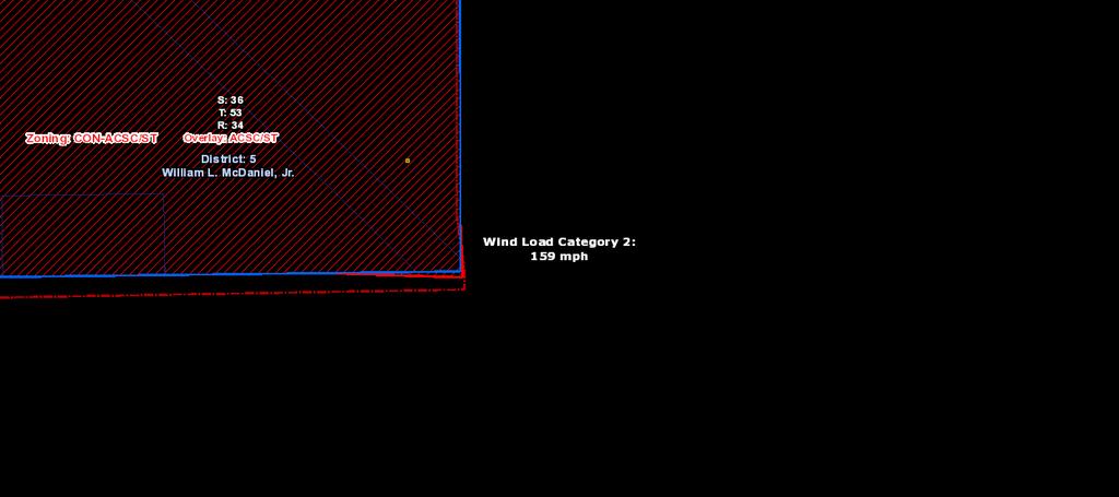
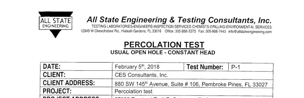
5 Stormwater Management Report Tamiami Trail East Ochopee, FL General Information 2.1. Flood Zone According to the Federal Emergency Management Agency (FEMA) flood insurance rate map community panel 12021C1225, the property is located within Flood Zone A (see Appendix 2). Zone A is defined as Areas subject to inundation by the 1-percent-annual-chance flood event generally determined using approximate methodologies. Because detailed hydraulic analyses have not been performed, no Base Flood Elevations (BFEs) or flood depths are shown Wetlands According to the National Wetlands Inventory of the US Fish and Wildlife Service, the property is located within classifications PFO3A and PSS2/EM5C, and the wetland type is Freshwater Forested/Shrub Wetland (see Appendix 3) Zoning The project site is located within zoning CON ACSC-ST, which is defined as Conservation Area of Critical State Concern - Special Treatment Overlay (Collier County) (see Appendix 4) Topographic Survey The topographic survey was provided by Amec Foster Wheeler E&I, Inc. (see Appendix 5). The project horizontal datum is relative to the North American Datum of 1983, 2011 adjustment (NAD83 (2011)) and US Survey Feet and elevations are relative to the North American Vertical Datum of 1988 (NAVD 88) Geotechnical Investigation A percolation test was performed by All State Engineering & Testing Consultant, Inc. in February 5, 2018 (see Appendix 6). A k-value of 1.83e-04 cfs/ft 2 ft-head (equivalent to feet per day (fpd)) resulted from the test. Seminole Tribe of Florida ollywood, FL 2
6 Stormwater Management Report Tamiami Trail East Ochopee, FL Basis of Analysis 3.1. Curve Numbers The guidelines for estimating the curve numbers of the South Florida Water Management District (SFWMD) were used to calculate the weighted runoff curve number for the project. The curve number was assumed to be 79 for low residential areas Time of Concentration The time of concentration is defined as the time it takes runoff to travel from the most remote point in the watershed to the point of interest. The time of concentration for the existing condition was calculated using the velocity method based on the slope of the ground and type of ground cover, as indicated in the Natural Resources Conservation Service (NRCS) methodology. The minimum time of concentration was set to 10 minutes Design Storm Depth, Frequency and Duration The design storms used to model the existing and proposed conditions are shown below in Table 1. Table 1. Design Storms Frequency (years) Duration (hours) Depth (inches) The rainfall distribution used was NRCS Type Groundwater Condition According to the NRCS soil survey webpage, soil data is not available to the project area. All State Engineering & Testing Consultant, Inc. reported that depth of water table below the ground surface was 7 feet during the percolation test. This value was used for modeling due Seasonal igh-water Level (SWL) is not available. Seminole Tribe of Florida ollywood, FL 3
7 Stormwater Management Report Tamiami Trail East Ochopee, FL Existing Condition The Seminole Tribe s property has a total area of 1.36 acres (ac), but only ac is affected by flooding around the house. Table 2 and Appendix 7 show the sub-basins draining around the house area. Table 2. Existing Drainage Sub-basins Sub-areas Area (ac) Draining to Area Low Point 1 (North of Walkway) Area Low Point 2 (South of Walkway) Area ouse and Existing Channel ICPR Input Parameters ICPR nodal diagram for the existing condition is shown in Appendix 8. The nodal diagram was based on the existing flow pattern. ICPR input parameters were: Unit ydrograph: U 256 Curve Number: 79 Time of Concentration: 10 minutes Rainfall Distribution: SCSII Rainfall Depths: o 6.5 inches for 10- yrs flood o 8.0 inches for 25- yrs flood o 10.0 inches for 100- yrs flood Tailwater Elevation: 7.3 ft NAVD 88 (water level at channel, per survey dated February 21, 2018) Pond Area 1 = ac (maximum area) Pond Area 2 = ac (maximum area) Groundwater Elevation = 4.0 feet NAVD 88 (7 ft below the average ground elevation) Vertical Conductivity = fpd orizontal Conductivity = 7.90 fpd (assumed as half of vertical conductivity) Fill Porosity = 0.30 (average value for lime sand) Seminole Tribe of Florida ollywood, FL 4
8 Stormwater Management Report Tamiami Trail East Ochopee, FL ICPR Results A summary of the existing condition results from ICPR model is shown in Table 3. Table 3. Existing Condition Model Results Node Name Simulation imum (ft) imum Inflow (cfs) imum Outflow (cfs) Pond-1 10yr 24hr Pond-2 10yr 24hr Canal 10yr 24hr Pond-1 25yr 24hr Pond-2 25yr 24hr Canal 25yr 24hr Pond-1 100yr 24hr Pond-2 100yr 24hr Canal 100yr 24hr Seminole Tribe of Florida ollywood, FL 5
9 Stormwater Management Report Tamiami Trail East Ochopee, FL Proposed Condition The proposed condition was divided in five sub-basins, each one draining to a proposed French drain and/or grate inlet. Table 4 and Appendix 10 show the sub-basins areas. Table 4. Proposed Drainage Sub-basins Sub-areas Area (ac) Draining to SB French Drain 1 / Grate Inlet 1 SB French Drain 2 / Grate Inlet 2 SB French Drain 3 / Grate Inlet 3 SB French Drain 4 / Grate Inlet 4 SB Grate Inlet ICPR Input Parameters The proposed drainage system has been designed as one comprehensive model including sub-basins, French drains, pipes, grates inlets and headwall with rip-rap protection. The nodal diagram was based on the proposed storm drainage system as shown in Appendix 11. ICPR input parameters are: Unit ydrograph: U 256 Curve Number: 79 Time of Concentration: 10 minutes for all basins. Rainfall Distribution: SCSII Rainfall Depths: o 6.5 inches for 10- yrs flood o 8.0 inches for 25- yrs flood o 10.0 inches for 100- yrs flood Tailwater Elevation: 7.3 feet NAVD 88 Initial = Pipe trench bottom (4 ft below RIM elevation) Warning was set to RIM elevation of grate inlets. Groundwater Elevation = 4.0 ft NAVD 88 (7 ft below the average ground elevation) Vertical Conductivity = (fpd) orizontal Conductivity = 7.90 fpd Gravel and Fill Porosity = 0.32 (graded gravel) Seminole Tribe of Florida ollywood, FL 6
10 Stormwater Management Report Tamiami Trail East Ochopee, FL ICPR Results Summaries of the RIM elevation of grate inlets versus the node maximum stage results, and links results from ICPR model are shown in Table 5 and Table 6. Table 5. Model Result RIM Elevation vs imum Elevation Grate Inlet RIM Elevation (ft) 10-yr. imum (ft) 25- yr. imum (ft) 100- yr. imum (ft) GI-# GI-# GI-# GI-# GI-# Table 6. Model Result Links Results Link. 10-yr. (cfs). 25-yr. (cfs). 100-yr. (cfs) FD FD FD FD Perc Perc Perc Perc P P P Seminole Tribe of Florida ollywood, FL 7
11 Stormwater Management Report Tamiami Trail East Ochopee, FL For more detailed information regarding link and node reports, please refer to Appendix 12. Table 7 shows a comparison between the existing and proposed condition discharges in the existing channel. The maximum flows (peak flows) for the proposed condition are lower than the existing condition for each one of the design rainfalls. Therefore, the proposed system does not have a negative impact on the existing channel. Table 7. Comparison Model Results Discharges in Existing Canal Simulation 10-yr. imum 25- yr. imum 100- yr. imum (cfs) (cfs) (cfs) Existing Proposed The proposed condition includes an exfiltration trench (French drain); the calculations for the design are shown in Appendix 13. The rip rap apron and design calculations can be found in Appendix 14. Seminole Tribe of Florida ollywood, FL 8
12 Stormwater Management Report Tamiami Trail East Ochopee, FL Conclusions and Recommendations 6.1. Conclusions According to the results of the models for existing conditions, the conclusions are the following: 1- Two ponding areas were identified in front of the house, based on the site survey. The largest area (Pond #1) is located north of the wood walkway and the smallest (Pond #2) is located south of the walkway. 2- Under design rainfalls, Pond #1 covers a maximum area of 1,702 square feet (sf) at a ft of water elevation, and Pond #2 covers a maximum area of 868 sf at a ft of water elevation approximately. 3- In the existing condition, the runoff is carried out through infiltration in the ponded areas. When the water level exceeds the local high points, the runoff is routed towards the existing channel. 4- For the proposed condition, the following infrastructure is proposed to avoid ponding and flooding: a combined system of earth swales, French drains, and pipes with discharge to the existing channel. The proposed system also includes grading to route runoff towards the earth swale and inlets. 5- The maximum flows (peak flows) for the proposed condition are lower than the existing condition for each one of the design rainfalls. Therefore, the proposed system does not have a negative impact on the existing channel. 6- To decrease flow velocity at the discharge point (proposed condition) near the existing channel, a riprap apron is recommended to spread the flow; this aids the transition to natural drainage Recommendations According to the results of the models for the proposed condition, the following is recommended: 1- French drain in the North, South and West sides of the house with the following characteristics: a. Trench width = 3.0 ft b. Trench height = 3.0 ft c. Trench depth below pipe invert = 1.0 ft d. Perforated pipe = 1.0 ft diameter e. Gravel porosity = 0.32 Seminole Tribe of Florida ollywood, FL 9
13 Stormwater Management Report Tamiami Trail East Ochopee, FL Earth swales on top of the French drain trenches were recommended to route runoff towards the grate inlets. Earth swales have a width of 3.0 ft and maximum depth of 0.5 ft. 3- Type C Ditch Bottom Inlets (per FDOT standards) to collect the runoff that runs through the earth swales. 4- PVC SDR-35 pipes in the East side of the house, to route the runoff that does not infiltrate, towards the existing channel. 12-inch diameter pipes are recommended, using slopes that result in 2 feet per second (fps) of minimum velocity. 5- A headwall is recommended in the end of drainage system to carry the flow towards the existing channel. The headwall used is U-type concrete endwall with steel grate (1:3 slope) per FDOT Index Number A rip-rap apron is recommended to spread the flow, aiding the transition to natural drainage. The rip rap apron has the following characteristics: a. Length = 6.0 ft b. Width = varying from 3.7 ft (headwall end) to 4.7 ft (existing channel) c. Depth = 1.5 ft maximum d. Average rock size = 6 inches 7- A periodic maintenance plan must be implemented to the proposed system, including cleanup of earth swales, grate inlets, pipes, headwall, and riprap. Seminole Tribe of Florida ollywood, FL 10
14 Stormwater Management Report Tamiami Trail East Ochopee, FL APPENDIX 1 Project Site Seminole Tribe of Florida ollywood, FL
15 Legend Boundary Yards Miami-Dade County GIS Groups Seminole tribe drainage study Project Boundary
16 Stormwater Management Report Tamiami Trail East Ochopee, FL APPENDIX 2 FEMA Map Seminole Tribe of Florida ollywood, FL
 Zone A, V, A99 With BFE or Depth Regulatory Floodway Zone AE, AO, A, VE, AR 0.")

17 National Flood azard Layer FIRMette 25 48'41.00"N Legend SEE FIS REPORT FOR DETAILED LEGEND AND INDEX MAP FOR FIRM PANEL LAYOUT 80 52'44.57"W SPECIAL FLOOD AZARD AREAS OTER AREAS OF FLOOD AZARD Without Base Flood Elevation (BFE) Zone A, V, A99 With BFE or Depth Regulatory Floodway Zone AE, AO, A, VE, AR 0.2% Annual Chance Flood azard, Areas of 1% annual chance flood with average depth less than one foot or with drainage areas of less than one square mile Zone X Future Conditions 1% Annual Chance Flood azard Zone X Area with Reduced Flood Risk due to Levee. See Notes. Zone X Area with Flood Risk due to Levee Zone D OTER AREAS GENERAL STRUCTURES NO SCREEN Area of Minimal Flood azard Zone X Effective LOMRs Area of Undetermined Flood azard Zone D Channel, Culvert, or Storm Sewer Levee, Dike, or Floodwall OTER FEATURES B Cross Sections with 1% Annual Chance 17.5 Water Surface Elevation Coastal Transect Base Flood Elevation Line (BFE) Limit of Study Jurisdiction Boundary Coastal Transect Baseline Profile Baseline ydrographic Feature Source: Esri, DigitalGlobe, GeoEye, Earthstar Geographics, CNES/Airbus DS, USDA, USGS, AeroGRID, IGN, and the GIS User Community Feet 25 48'8.61"N 1:6, ,000 1,500 2, '7.11"W MAP PANELS Digital Data Available No Digital Data Available Unmapped This map complies with FEMA's standards for the use of digital flood maps if it is not void as described below. The base map shown complies with FEMA's base map accuracy standards Ü The flood hazard information is derived directly from the authoritative NFL web services provided by FEMA. This map was exported on 3/22/2018 at 8:52:34 AM and does not reflect changes or amendments subsequent to this date and time. The NFL and effective information may change or become superseded by new data over time. This map image is void if the one or more of the following map elements do not appear: base map imagery, flood zone labels, legend, scale bar, map creation date, community identifiers, FIRM panel number, and FIRM effective date. Map images for unmapped and unmodernized areas cannot be used for regulatory purposes.
18 Stormwater Management Report Tamiami Trail East Ochopee, FL APPENDIX 3 Wetland Map Seminole Tribe of Florida ollywood, FL

19 57985 Tamiami Trail East 1:4, mi km U.S. Fish and Wildlife Service, National Standards and Support Team, wetlands_team@fws.gov March 22, 2018 Wetlands Estuarine and Marine Deepwater Freshwater Emergent Wetland Freshwater Forested/Shrub Wetland Lake Other This map is for general reference only. The US Fish and Wildlife Service is not responsible for the accuracy or currentness of the base data shown on this map. All wetlands related data should be used in accordance with the layer metadata found on the Wetlands Mapper web site. Estuarine and Marine Wetland Freshwater Pond Riverine National Wetlands Inventory (NWI) This page was produced by the NWI mapper
20 Stormwater Management Report Tamiami Trail East Ochopee, FL APPENDIX 4 Zoning Map Seminole Tribe of Florida ollywood, FL


21 + Collier Geocoder Zoning Map with Web AppBuilder for ArcGIS 400ft Degrees
22 Stormwater Management Report Tamiami Trail East Ochopee, FL APPENDIX 5 Topographic Survey Seminole Tribe of Florida ollywood, FL
23 50.1' 14.8' N SCALE: 1" - 10' SEPTIC MOUND LIMESTONE DRIVEWAY 'x4' CONCRETE A/C PAD (top elevation = 11.25' ' ' ' OVERANG STORY WOOD POLE BARN ' LIMESTONE DRIVEWAY CONCRETE SLAB ' WOOD WALKWAY Site Benchmark #130 Corner of concrete Elevation = 11.08' E COVERED CONCRETE PORC 1 STORY CONCRETE BLOCK OUSE (Finished Floor Elevation = 11.26') 30.2' ' Satellite dish CO ' 8.2' ' WOOD LINE WATERS EDGE Elevation = 7.3' (February 21, 2018) ' STORY WOOD FRAME SED ON CONCRETE SLAB ' SEMINOLE TRIBE OF FLORIDA TAMIAMI TRAIL DRAINAGE EXISTING CONDITIONS SURVEY ENG. OF RECORD: L.C.M. DESIGN ENGINEER: DRAWN BY: E.A. E.C. CECKER: D.. SCALE: AS NOTED ENGINEER OF RECORD: 1 NO. 3/23/18 DATE 100% DESIGN SUBMITTAL REVISION APP'D. BY File Name: Survey Reference: Field Book: Date: Page: Sheet: Work Order: Drawing: C-01
24 Stormwater Management Report Tamiami Trail East Ochopee, FL APPENDIX 6 Percolation Test Seminole Tribe of Florida ollywood, FL
25
26 Stormwater Management Report Tamiami Trail East Ochopee, FL APPENDIX 7 Existing Drainage Sub-basins Seminole Tribe of Florida ollywood, FL
27 50.1' 14.8' N SCALE: 1" - 10' SEPTIC MOUND LIMESTONE DRIVEWAY 'x4' CONCRETE A/C PAD (top elevation = 11.25' ' ' ' OVERANG STORY WOOD POLE BARN ' LIMESTONE DRIVEWAY CONCRETE SLAB ' WOOD WALKWAY Site Benchmark #130 Corner of concrete Elevation = 11.08' E COVERED CONCRETE PORC 1 STORY CONCRETE BLOCK OUSE (Finished Floor Elevation = 11.26') 30.2' ' Satellite dish CO ' 8.2' ' WOOD LINE WATERS EDGE Elevation = 7.3' (February 21, 2018) ' STORY WOOD FRAME SED ON CONCRETE SLAB ' SEMINOLE TRIBE OF FLORIDA TAMIAMI TRAIL DRAINAGE EXISTING CONDITIONS DRAINAGE SUB-BASINS ENG. OF RECORD: L.C.M. DESIGN ENGINEER: DRAWN BY: E.A. E.C. CECKER: D.. SCALE: AS NOTED ENGINEER OF RECORD: 1 NO. 3/23/18 DATE 100% DESIGN SUBMITTAL REVISION APP'D. BY File Name: Survey Reference: Field Book: Date: Page: Sheet: Work Order: Drawing: C-01
28 Stormwater Management Report Tamiami Trail East Ochopee, FL APPENDIX 8 ICPR Nodal Diagram for Existing Condition Seminole Tribe of Florida ollywood, FL
29 1 Background Image: Nodal Diagram C:\Users\lcruz\Documents\Projects\Seminole Tribes\Existing Conditions Seminole\ 3/27/ :00
30 Stormwater Management Report Tamiami Trail East Ochopee, FL APPENDIX 9 ICPR Model Results for Existing Condition Seminole Tribe of Florida ollywood, FL
31 1 Background Image: Nodal Diagram Curve Number: 1 [Set] Land Cover Zone Soil Zone Curve Number [dec] Impervious C 98.0 Pervious C 79.0 Manual Basin: Area-1 Scenario: Scenario1 Node: Pond-1 ydrograph Method: NRCS Unit ydrograph Infiltration Method: Curve Number Time of Concentration: min Allowable Q: 0.00 cfs Time Shift: hr Unit ydrograph: U256 Peaking Factor: Area [ac] Land Cover Zone Soil Zone Rainfall Name Pervious C Comment: C:\Users\lcruz\Documents\Projects\Seminole Tribes\ICPR Model\Existing Conditions Seminole\ 3/28/ :51
32 2 Manual Basin: Area-2 Scenario: Scenario1 Node: Pond-2 ydrograph Method: NRCS Unit ydrograph Infiltration Method: Curve Number Time of Concentration: min Allowable Q: 0.00 cfs Time Shift: hr Unit ydrograph: U256 Peaking Factor: Area [ac] Land Cover Zone Soil Zone Rainfall Name Pervious C Comment: Manual Basin: Area-3 Scenario: Scenario1 Node: Canal ydrograph Method: NRCS Unit ydrograph Infiltration Method: Curve Number Time of Concentration: min Allowable Q: 0.00 cfs Time Shift: hr Unit ydrograph: U256 Peaking Factor: Area [ac] Land Cover Zone Soil Zone Rainfall Name Pervious C Comment: Node: Canal Scenario: Type: Base : Initial : Warning : Boundary : Scenario1 Time/ 0.00 cfs 7.30 ft 8.00 ft Year Month Day our Comment: C:\Users\lcruz\Documents\Projects\Seminole Tribes\ICPR Model\Existing Conditions Seminole\ 3/28/ :51
33 3 Node Conditions w/ Times [Scenario1] Node Sim Name Name Canal 010Y-24 Canal 025Y-24 Canal 100Y-24 Warning Min/ Inflow Outflow Surface Area [ft2] Min/ Inflow Outflow Node : Canal [Scenario1] Node: GW Scenario: Type: Base : Scenario1 Time/ 0.00 cfs C:\Users\lcruz\Documents\Projects\Seminole Tribes\ICPR Model\Existing Conditions Seminole\ 3/28/ :51
34 4 Initial : Warning : Boundary : 4.00 ft 7.00 ft Year Month Day our Comment: Node Conditions w/ Times [Scenario1] Node Sim Name Name GW 010Y-24 GW 025Y-24 GW 100Y-24 Warning Min/ Inflow Outflow Surface Area [ft2] Min/ Inflow Outflow C:\Users\lcruz\Documents\Projects\Seminole Tribes\ICPR Model\Existing Conditions Seminole\ 3/28/ :51
35 5 Node : GW [Scenario1] Node: Pond-1 Scenario: Type: Base : Initial : Warning : Scenario1 /Area 0.00 cfs ft ft Area [ac] Area [ft2] Comment: Node Conditions w/ Times [Scenario1] Node Sim Warning Min/ Name Name Surface Min/ Inflow Outflow Area C:\Users\lcruz\Documents\Projects\Seminole Tribes\ICPR Model\Existing Conditions Seminole\ 3/28/ :51
36 6 Node Sim Name Name Pond-1 010Y-24 Pond-1 025Y-24 Pond-1 100Y-24 Warning Min/ Inflow Outflow Surface Area [ft2] Min/ Inflow Outflow Node : Pond-1 [Scenario1] Node: Pond-2 Scenario: Type: Base : Initial : Scenario1 /Area 0.00 cfs ft C:\Users\lcruz\Documents\Projects\Seminole Tribes\ICPR Model\Existing Conditions Seminole\ 3/28/ :51
37 7 Warning : ft Area [ac] Area [ft2] Comment: Node Conditions w/ Times [Scenario1] Node Sim Name Name Pond-2 010Y-24 Pond-2 025Y-24 Pond-2 100Y-24 Warning Min/ Inflow Outflow Surface Area [ft2] Min/ Inflow Outflow C:\Users\lcruz\Documents\Projects\Seminole Tribes\ICPR Model\Existing Conditions Seminole\ 3/28/ :51
38 8 Node : Pond-2 [Scenario1] Percolation Link: Perc-1 Scenario: Scenario1 From Node: Pond-1 To Node: GW Link Count: 1 Direction: Both Aquifer Base Elevation: 0.00 ft Water Table Elevation: 4.00 ft Annual Recharge Rate: 0 ipy orizontal Conductivity: fpd Vertical Conductivity: fpd Fillable Porosity: Layer Thickness: 6.86 ft Comment: Surface Area Option: Vary Based on /Area Table Vertical Termination: orizontal Algorithm Perimeter 1: ft Perimeter 2: ft Perimeter 3: ft Distance P1 to P2: ft Distance P2 to P3: ft # of Cells P1 to P2: 4 # of Cells P2 to P3: 3 Link Min/ Conditions with Times [Scenario1] Link Sim Min Min/ Us Ds C:\Users\lcruz\Documents\Projects\Seminole Tribes\ICPR Model\Existing Conditions Seminole\ 3/28/ :51
39 9 Link Sim Name Name Perc-1 010Y-24 Perc-1 025Y-24 Perc-1 100Y-24 Min Min/ Us [fps] Ds [fps] Min Min/ Us Ds Link : Perc-1 [Scenario1] Percolation Link: Perc-2 Scenario: Scenario1 From Node: Pond-2 To Node: GW Link Count: 1 Surface Area Option: Vertical Termination: Perimeter 1: Vary Based on /Area Table orizontal Algorithm ft C:\Users\lcruz\Documents\Projects\Seminole Tribes\ICPR Model\Existing Conditions Seminole\ 3/28/ :51
40 10 Direction: Both Aquifer Base Elevation: 0.00 ft Water Table Elevation: 4.00 ft Annual Recharge Rate: 0 ipy orizontal Conductivity: fpd Vertical Conductivity: fpd Fillable Porosity: Layer Thickness: 6.81 ft Comment: Perimeter 2: ft Perimeter 3: ft Distance P1 to P2: ft Distance P2 to P3: ft # of Cells P1 to P2: 4 # of Cells P2 to P3: 3 Link Min/ Conditions with Times [Scenario1] Link Sim Name Name Perc-2 010Y-24 Perc-2 025Y-24 Perc-2 100Y-24 Min Min/ Us [fps] Ds [fps] Min Min/ Us Ds C:\Users\lcruz\Documents\Projects\Seminole Tribes\ICPR Model\Existing Conditions Seminole\ 3/28/ :51
41 11 Link : Perc-2 [Scenario1] Weir Link: Weir-1 Scenario: Scenario1 From Node: Pond-1 To Node: Pond-2 Link Count: 1 Direction: Both Damping: ft Weir Type: Broad Crested Vertical Geometry Type: Irregular Invert: ft Control Elevation: ft Cross Section: CS-1 Comment: Bottom Clip Default: 0.00 ft Op Table: Ref Node: Top Clip Default: 0.00 ft Op Table: Ref Node: Discharge Coefficients Weir Default: Weir Table: Orifice Default: Orifice Table: Link Min/ Conditions with Times [Scenario1] C:\Users\lcruz\Documents\Projects\Seminole Tribes\ICPR Model\Existing Conditions Seminole\ 3/28/ :51
![12 Link Sim Name Name Weir-1 010Y-24 Weir-1 025Y-24 Weir-1 100Y-24 Min Min/ Us [fps] Ds [fps] Min Min/ Us Ds 0.58-0.08-0.44 0.26 0.26 12.0574 0.0000 12.0595 12.0574 12.0574 0.77-0.08-0.60 0.31 0.](/docs-images/81/83624490/images/42-0.jpg "31 12.0748 0.0000 12.1144 12.1110 12.1110 1.01-0.08 0.58 0.35 0.35 12.0867 0.0000 12.0867 12.")
42 12 Link Sim Name Name Weir-1 010Y-24 Weir-1 025Y-24 Weir-1 100Y-24 Min Min/ Us [fps] Ds [fps] Min Min/ Us Ds Link : Weir-1 [Scenario1] Weir Link: Weir-2 Scenario: Scenario1 From Node: Pond-2 To Node: Canal Link Count: 1 Bottom Clip Default: 0.00 ft Op Table: Ref Node: C:\Users\lcruz\Documents\Projects\Seminole Tribes\ICPR Model\Existing Conditions Seminole\ 3/28/ :51
43 13 Direction: Both Damping: ft Top Clip Weir Type: Sharp Crested Vertical Default: 0.00 ft Geometry Type: Irregular Op Table: Invert: ft Ref Node: Control Elevation: ft Discharge Coefficients Cross Section: CS-2 Weir Default: Weir Table: Orifice Default: Orifice Table: Comment: Link Min/ Conditions with Times [Scenario1] Link Sim Name Name Weir-2 010Y-24 Weir-2 025Y-24 Weir-2 100Y-24 Min Min/ Us [fps] Ds [fps] Min Min/ Us Ds C:\Users\lcruz\Documents\Projects\Seminole Tribes\ICPR Model\Existing Conditions Seminole\ 3/28/ :51
44 14 Link : Weir-2 [Scenario1] C:\Users\lcruz\Documents\Projects\Seminole Tribes\ICPR Model\Existing Conditions Seminole\ 3/28/ :51
45 Stormwater Management Report Tamiami Trail East Ochopee, FL APPENDIX 10 Proposed Drainage Sub-basins Seminole Tribe of Florida ollywood, FL
 15.5' 8.2' LIMESTONE DRIVEWAY Site Benchmark #130 Corner of concrete Elevation = 11.08' E 19.")

46 50.1' 14.8' N SCALE: 1" - 10' SEPTIC MOUND LIMESTONE DRIVEWAY 'x4' CONCRETE A/C PAD (top elevation = 11.25' 30.2' 2.3' OVERANG 20.0' 1 STORY WOOD POLE BARN COVERED CONCRETE PORC 8.2' WOOD LINE 23.8' 3' WOOD WALKWAY 1 STORY CONCRETE BLOCK OUSE (Finished Floor Elevation = 11.26') 15.5' 8.2' LIMESTONE DRIVEWAY Site Benchmark #130 Corner of concrete Elevation = 11.08' E 19.8' WATERS EDGE Elevation = 7.3' (February 21, 2018) 30.2' CONCRETE SLAB Satellite dish ' 1 STORY WOOD FRAME SED ON CONCRETE SLAB 20.3' SEMINOLE TRIBE OF FLORIDA TAMIAMI TRAIL DRAINAGE PROPOSED GRADING AND DRAINAGE DRAINAGE SUB-BASINS ENG. OF RECORD: L.C.M. DESIGN ENGINEER: DRAWN BY: E.A. E.C. CECKER: D.. SCALE: AS NOTED ENGINEER OF RECORD: 1 NO. 3/23/18 DATE 100% DESIGN SUBMITTAL REVISION APP'D. BY File Name: Survey Reference: Field Book: Date: Page: Sheet: Work Order: Drawing: C-02
47 Stormwater Management Report Tamiami Trail East Ochopee, FL APPENDIX 11 ICPR Nodal Diagram for Proposed Condition Seminole Tribe of Florida ollywood, FL
48 1 Background Image: Nodal Network C:\Users\lcruz\Documents\Projects\Seminole Tribes\Seminole Tribe - SS Model\ 3/27/ :46
49 Stormwater Management Report Tamiami Trail East Ochopee, FL APPENDIX 12 ICPR Model Results for Proposed Condition Seminole Tribe of Florida ollywood, FL
50 1 Background Image: Nodal Network Curve Number: 1 [Set] Land Cover Zone Soil Zone Curve Number [dec] Impervious A 98.0 Pervious C 79.0 C:\Users\lcruz\Documents\Projects\Seminole Tribes\ICPR Model\Seminole Tribe - SS Model\ 3/28/ :33
51 2 Manual Basin: SB-1 Scenario: Scenario1 Node: C-1 ydrograph Method: NRCS Unit ydrograph Infiltration Method: Curve Number Time of Concentration: min Allowable Q: 0.00 cfs Time Shift: hr Unit ydrograph: U256 Peaking Factor: Area [ac] Land Cover Zone Soil Zone Rainfall Name Pervious C Comment: Manual Basin Runoff Summary [Scenario1] Basin Sim Name Area [ac] Equivalent % Imperv % DCIA Name Rainfall [in] Runoff [in] Curve Number SB-1 010Y SB-1 025Y SB-1 100Y C:\Users\lcruz\Documents\Projects\Seminole Tribes\ICPR Model\Seminole Tribe - SS Model\ 3/28/ :33
52 3 Manual Basin Runoff Rate: SB-1 [Scenario1] Manual Basin: SB-2 Scenario: Scenario1 Node: GI-1 ydrograph Method: NRCS Unit ydrograph Infiltration Method: Curve Number Time of Concentration: min Allowable Q: 0.00 cfs Time Shift: hr Unit ydrograph: U256 Peaking Factor: Area [ac] Land Cover Zone Soil Zone Rainfall Name Pervious C Comment: Manual Basin Runoff Summary [Scenario1] Basin Sim Name Area [ac] Equivalent % Imperv % DCIA C:\Users\lcruz\Documents\Projects\Seminole Tribes\ICPR Model\Seminole Tribe - SS Model\ 3/28/ :33
53 4 Basin Sim Name Area [ac] Equivalent % Imperv % DCIA Name Rainfall [in] Runoff [in] Curve Number SB-2 010Y SB-2 025Y SB-2 100Y Manual Basin Runoff Rate: SB-2 [Scenario1] Manual Basin: SB-3 Scenario: Scenario1 Node: C-2 ydrograph Method: NRCS Unit ydrograph Infiltration Method: Curve Number Time of Concentration: min Allowable Q: 0.00 cfs Time Shift: hr Unit ydrograph: U256 Peaking Factor: C:\Users\lcruz\Documents\Projects\Seminole Tribes\ICPR Model\Seminole Tribe - SS Model\ 3/28/ :33
54 5 Area [ac] Land Cover Zone Soil Zone Rainfall Name Pervious C Comment: Manual Basin Runoff Summary [Scenario1] Basin Sim Name Area [ac] Equivalent % Imperv % DCIA Name Rainfall [in] Runoff [in] Curve Number SB-3 010Y SB-3 025Y SB-3 100Y Manual Basin Runoff Rate: SB-3 [Scenario1] Manual Basin: SB-4 C:\Users\lcruz\Documents\Projects\Seminole Tribes\ICPR Model\Seminole Tribe - SS Model\ 3/28/ :33
55 6 Scenario: Scenario1 Node: GI-3 ydrograph Method: NRCS Unit ydrograph Infiltration Method: Curve Number Time of Concentration: min Allowable Q: 0.00 cfs Time Shift: hr Unit ydrograph: U256 Peaking Factor: Area [ac] Land Cover Zone Soil Zone Rainfall Name Pervious C Comment: Manual Basin Runoff Summary [Scenario1] Basin Sim Name Area [ac] Equivalent % Imperv % DCIA Name Rainfall [in] Runoff [in] Curve Number SB-4 010Y SB-4 025Y SB-4 100Y C:\Users\lcruz\Documents\Projects\Seminole Tribes\ICPR Model\Seminole Tribe - SS Model\ 3/28/ :33
56 7 Manual Basin Runoff Rate: SB-4 [Scenario1] Manual Basin: SB-5 Scenario: Scenario1 Node: GI-5 ydrograph Method: NRCS Unit ydrograph Infiltration Method: Curve Number Time of Concentration: min Allowable Q: 0.00 cfs Time Shift: hr Unit ydrograph: U256 Peaking Factor: Area [ac] Land Cover Zone Soil Zone Rainfall Name Pervious C Comment: Manual Basin Runoff Summary [Scenario1] Basin Sim Name Area [ac] Equivalent % Imperv % DCIA C:\Users\lcruz\Documents\Projects\Seminole Tribes\ICPR Model\Seminole Tribe - SS Model\ 3/28/ :33
57 8 Basin Sim Name Area [ac] Equivalent % Imperv % DCIA Name Rainfall [in] Runoff [in] Curve Number SB-5 010Y SB-5 025Y SB-5 100Y Manual Basin Runoff Rate: SB-5 [Scenario1] Node: C-1 Scenario: Type: Base : Initial : Warning : Scenario1 /Area 0.00 cfs 7.82 ft ft Comment: C:\Users\lcruz\Documents\Projects\Seminole Tribes\ICPR Model\Seminole Tribe - SS Model\ 3/28/ :33
58 9 Node Conditions w/ Times [Scenario1] Node Sim Name Name C-1 010Y-24 C-1 025Y-24 C-1 100Y-24 Warning Min/ Inflow Outflow Surface Area [ft2] Min/ Inflow Outflow Node : C-1 [Scenario1] Node: C-2 Scenario: Type: Base : Scenario1 /Area 0.00 cfs C:\Users\lcruz\Documents\Projects\Seminole Tribes\ICPR Model\Seminole Tribe - SS Model\ 3/28/ :33
59 10 Initial : Warning : 7.74 ft ft Comment: Node Conditions w/ Times [Scenario1] Node Sim Name Name C-2 010Y-24 C-2 025Y-24 C-2 100Y-24 Warning Min/ Inflow Outflow Surface Area [ft2] Min/ Inflow Outflow C:\Users\lcruz\Documents\Projects\Seminole Tribes\ICPR Model\Seminole Tribe - SS Model\ 3/28/ :33
![11 Node : C-2 [Scenario1] Node: Canal Scenario: Type: Base : Initial : Warning : Boundary : Scenario1 Time/ 0.00 cfs 7.50 ft 11.00 ft Year Month Day our 0 0 0 0.0000 7.](/docs-images/81/83624490/images/60-0.jpg "30 0 0 0 9999.0000 7.")
60 11 Node : C-2 [Scenario1] Node: Canal Scenario: Type: Base : Initial : Warning : Boundary : Scenario1 Time/ 0.00 cfs 7.50 ft ft Year Month Day our Comment: Node Conditions w/ Times [Scenario1] Node Sim Warning Min/ Name Name Surface Min/ C:\Users\lcruz\Documents\Projects\Seminole Tribes\ICPR Model\Seminole Tribe - SS Model\ 3/28/ :33
61 12 Node Sim Name Name Canal 010Y-24 Canal 025Y-24 Canal 100Y-24 Warning Min/ Inflow Outflow Surface Area [ft2] Min/ Inflow Outflow Node : Canal [Scenario1] Node: GI-1 Scenario: Type: Base : Initial : Scenario1 /Area 0.00 cfs 6.21 ft C:\Users\lcruz\Documents\Projects\Seminole Tribes\ICPR Model\Seminole Tribe - SS Model\ 3/28/ :33
62 13 Warning : ft Area [ac] Area [ft2] Comment: Node Conditions w/ Times [Scenario1] Node Sim Name Name GI-1 010Y-24 GI-1 025Y-24 GI-1 100Y-24 Warning Min/ Inflow Outflow Surface Area [ft2] Min/ Inflow Outflow C:\Users\lcruz\Documents\Projects\Seminole Tribes\ICPR Model\Seminole Tribe - SS Model\ 3/28/ :33
![14 Node : GI-1 [Scenario1] Node: GI-2 Scenario: Type: Base : Initial : Warning : Scenario1 /Area 0.00 cfs 5.80 ft 9.80 ft Area [ac] Area [ft2] 5.80 0.](/docs-images/81/83624490/images/63-0.jpg "0033 145 9.80 0.")
63 14 Node : GI-1 [Scenario1] Node: GI-2 Scenario: Type: Base : Initial : Warning : Scenario1 /Area 0.00 cfs 5.80 ft 9.80 ft Area [ac] Area [ft2] Comment: Node Conditions w/ Times [Scenario1] Node Sim Warning Min/ Name Name Surface Min/ Inflow Outflow Area C:\Users\lcruz\Documents\Projects\Seminole Tribes\ICPR Model\Seminole Tribe - SS Model\ 3/28/ :33
64 15 Node Sim Name Name GI-2 010Y-24 GI-2 025Y-24 GI-2 100Y-24 Warning Min/ Inflow Outflow Surface Area [ft2] Min/ Inflow Outflow Node : GI-2 [Scenario1] Node: GI-3 Scenario: Type: Base : Initial : Scenario1 /Area 0.00 cfs 6.27 ft C:\Users\lcruz\Documents\Projects\Seminole Tribes\ICPR Model\Seminole Tribe - SS Model\ 3/28/ :33
65 16 Warning : ft Area [ac] Area [ft2] Comment: Node Conditions w/ Times [Scenario1] Node Sim Name Name GI-3 010Y-24 GI-3 025Y-24 GI-3 100Y-24 Warning Min/ Inflow Outflow Surface Area [ft2] Min/ Inflow Outflow C:\Users\lcruz\Documents\Projects\Seminole Tribes\ICPR Model\Seminole Tribe - SS Model\ 3/28/ :33
66 17 Node : GI-3 [Scenario1] Node: GI-4 Scenario: Type: Base : Initial : Warning : Scenario1 /Area 0.00 cfs 6.00 ft ft Area [ac] Area [ft2] Comment: Node Conditions w/ Times [Scenario1] Node Sim Warning Min/ Name Name Surface Min/ Inflow Outflow Area C:\Users\lcruz\Documents\Projects\Seminole Tribes\ICPR Model\Seminole Tribe - SS Model\ 3/28/ :33
67 18 Node Sim Name Name GI-4 010Y-24 GI-4 025Y-24 GI-4 100Y-24 Warning Min/ Inflow Outflow Surface Area [ft2] Min/ Inflow Outflow Node : GI-4 [Scenario1] Node: GI-5 Scenario: Type: Base : Initial : Scenario1 /Area 0.00 cfs 7.56 ft C:\Users\lcruz\Documents\Projects\Seminole Tribes\ICPR Model\Seminole Tribe - SS Model\ 3/28/ :33
68 19 Warning : ft Comment: Node Conditions w/ Times [Scenario1] Node Sim Name Name GI-5 010Y-24 GI-5 025Y-24 GI-5 100Y-24 Warning Min/ Inflow Outflow Surface Area [ft2] Min/ Inflow Outflow Node : GI-5 [Scenario1] C:\Users\lcruz\Documents\Projects\Seminole Tribes\ICPR Model\Seminole Tribe - SS Model\ 3/28/ :33
69 20 Node: GW-North Scenario: Type: Base : Initial : Warning : Boundary : Scenario1 Time/ 0.00 cfs 4.00 ft 6.50 ft Year Month Day our Comment: Node Conditions w/ Times [Scenario1] Node Name Sim Name GW-Nor 010Y-24 th GW-Nor 025Y-24 th GW-Nor 100Y-24 th Warning Min/ Inflow Outflow Surface Area [ft2] Min/ Inflow Outflow C:\Users\lcruz\Documents\Projects\Seminole Tribes\ICPR Model\Seminole Tribe - SS Model\ 3/28/ :33
70 21 Node : GW-North [Scenario1] Node: GW-South Scenario: Type: Base : Initial : Warning : Boundary : Scenario1 Time/ 0.00 cfs 4.00 ft 6.50 ft Year Month Day our Comment: Node Conditions w/ Times [Scenario1] Node Sim Warning Min/ Name Name Surface Min/ C:\Users\lcruz\Documents\Projects\Seminole Tribes\ICPR Model\Seminole Tribe - SS Model\ 3/28/ :33
71 22 Node Name GW-Sou th GW-Sou th GW-Sou th Sim Name 010Y Y Y-24 Warning Min/ Inflow Outflow Surface Area [ft2] Min/ Inflow Outflow Node : GW-South [Scenario1] French Drain Link: FD-1 Scenario: Scenario1 From Node: C-1 To Node: GI-1 Link Count: 1 Pipe Data Damping: ft FWA Code: 0 Entr Loss Coef: 0.00 Exit Loss Coef: 0.00 C:\Users\lcruz\Documents\Projects\Seminole Tribes\ICPR Model\Seminole Tribe - SS Model\ 3/28/ :33
72 23 Direction: Both Trench Length: ft Trench Width: 3.00 ft Trench eight: 3.00 ft Trench Depth Below Invert: 1.00 ft Trench Gravel Porosity: Comment: Pipe Data Bend Loss Coef: 0.00 Bend Location: 0.00 ft Energy Switch: Energy Pipe Length: ft Pipe Invert: 7.82 ft Pipe Invert: 7.78 ft Manning's N: Geometry Type: Circular Pipe Depth: 1.00 ft Link Min/ Conditions with Times [Scenario1] Link Sim Name Name FD-1 010Y-24 FD-1 025Y-24 FD-1 100Y-24 Min Min/ Us [fps] Ds [fps] Min Min/ Us Ds C:\Users\lcruz\Documents\Projects\Seminole Tribes\ICPR Model\Seminole Tribe - SS Model\ 3/28/ :33
73 24 Link : FD-1 [Scenario1] French Drain Link: FD-2 Scenario: Scenario1 From Node: GI-1 To Node: GI-2 Link Count: 1 Direction: Both Trench Length: ft Trench Width: 3.00 ft Trench eight: 3.00 ft Trench Depth Below Invert: 1.00 ft Trench Gravel Porosity: Comment: Pipe Data Damping: ft FWA Code: 0 Entr Loss Coef: 0.00 Exit Loss Coef: 0.00 Bend Loss Coef: 0.00 Bend Location: 0.00 ft Energy Switch: Energy Pipe Length: ft Pipe Invert: 7.78 ft Pipe Invert: 7.71 ft Manning's N: Geometry Type: Circular Pipe Depth: 1.00 ft Link Min/ Conditions with Times [Scenario1] C:\Users\lcruz\Documents\Projects\Seminole Tribes\ICPR Model\Seminole Tribe - SS Model\ 3/28/ :33
74 25 Link Sim Name Name FD-2 010Y-24 FD-2 025Y-24 FD-2 100Y-24 Min Min/ Us [fps] Ds [fps] Min Min/ Us Ds Link : FD-2 [Scenario1] French Drain Link: FD-3 Scenario: Scenario1 From Node: C-2 To Node: GI-3 Link Count: 1 Pipe Data Damping: ft FWA Code: 0 Entr Loss Coef: 0.00 Exit Loss Coef: 0.00 C:\Users\lcruz\Documents\Projects\Seminole Tribes\ICPR Model\Seminole Tribe - SS Model\ 3/28/ :33
75 26 Direction: Both Trench Length: ft Trench Width: 3.00 ft Trench eight: 3.00 ft Trench Depth Below Invert: 1.00 ft Trench Gravel Porosity: Comment: Pipe Data Bend Loss Coef: 0.00 Bend Location: 0.00 ft Energy Switch: Energy Pipe Length: ft Pipe Invert: 7.74 ft Pipe Invert: 7.71 ft Manning's N: Geometry Type: Circular Pipe Depth: 1.00 ft Link Min/ Conditions with Times [Scenario1] Link Sim Name Name FD-3 010Y-24 FD-3 025Y-24 FD-3 100Y-24 Min Min/ Us [fps] Ds [fps] Min Min/ Us Ds C:\Users\lcruz\Documents\Projects\Seminole Tribes\ICPR Model\Seminole Tribe - SS Model\ 3/28/ :33
76 27 Link : FD-3 [Scenario1] French Drain Link: FD-4 Scenario: Scenario1 From Node: GI-3 To Node: GI-4 Link Count: 1 Direction: Both Trench Length: ft Trench Width: 3.00 ft Trench eight: 3.00 ft Trench Depth Below Invert: 1.00 ft Trench Gravel Porosity: Comment: Pipe Data Damping: ft FWA Code: 0 Entr Loss Coef: 0.00 Exit Loss Coef: 0.00 Bend Loss Coef: 0.00 Bend Location: 0.00 ft Energy Switch: Energy Pipe Length: ft Pipe Invert: 7.71 ft Pipe Invert: 7.63 ft Manning's N: Geometry Type: Circular Pipe Depth: 1.00 ft Link Min/ Conditions with Times [Scenario1] C:\Users\lcruz\Documents\Projects\Seminole Tribes\ICPR Model\Seminole Tribe - SS Model\ 3/28/ :33
77 28 Link Sim Name Name FD-4 010Y-24 FD-4 025Y-24 FD-4 100Y-24 Min Min/ Us [fps] Ds [fps] Min Min/ Us Ds Link : FD-4 [Scenario1] Pipe Link: P-1 Scenario: Scenario1 From Node: GI-4 To Node: GI-5 Link Count: 1 Upstream Downstream Invert: 7.63 ft Invert: 7.56 ft Manning's N: Manning's N: Geometry: Circular Geometry: Circular Depth: 1.00 ft Depth: 1.00 ft C:\Users\lcruz\Documents\Projects\Seminole Tribes\ICPR Model\Seminole Tribe - SS Model\ 3/28/ :33
78 29 Direction: Positive Damping: ft Length: ft FWA Code: 0 Entr Loss Coef: 0.00 Exit Loss Coef: 0.00 Bend Loss Coef: 0.00 Bend Location: 0.00 ft Energy Switch: Energy Comment: Bottom Clip Default: 0.00 ft Default: 0.00 ft Op Table: Op Table: Ref Node: Ref Node: Manning's N: Manning's N: Top Clip Default: 0.00 ft Default: 0.00 ft Op Table: Op Table: Ref Node: Ref Node: Manning's N: Manning's N: Link Min/ Conditions with Times [Scenario1] Link Sim Name Name P-1 010Y-24 P-1 025Y-24 P-1 100Y-24 Min Min/ Us [fps] Ds [fps] Min Min/ Us Ds C:\Users\lcruz\Documents\Projects\Seminole Tribes\ICPR Model\Seminole Tribe - SS Model\ 3/28/ :33
79 30 Link : P-1 [Scenario1] Pipe Link: P-2 Scenario: Scenario1 From Node: GI-2 To Node: GI-5 Link Count: 1 Direction: Positive Damping: ft Length: ft FWA Code: 0 Entr Loss Coef: 0.00 Exit Loss Coef: 0.00 Bend Loss Coef: 0.00 Bend Location: 0.00 ft Energy Switch: Energy Comment: Upstream Downstream Invert: 7.71 ft Invert: 7.64 ft Manning's N: Manning's N: Geometry: Circular Geometry: Circular Depth: 1.00 ft Depth: 1.00 ft Bottom Clip Default: 0.00 ft Default: 0.00 ft Op Table: Op Table: Ref Node: Ref Node: Manning's N: Manning's N: Top Clip Default: 0.00 ft Default: 0.00 ft Op Table: Op Table: Ref Node: Ref Node: Manning's N: Manning's N: C:\Users\lcruz\Documents\Projects\Seminole Tribes\ICPR Model\Seminole Tribe - SS Model\ 3/28/ :33
WATER MANAGEMENT REPORT FOR PAGE ESTATES
 WATER MANAGEMENT REPORT FOR PAGE ESTATES SLB Consulting of SW Florida, LLC PO Box 2826 Bonita Springs, FL. 34133 Phone: 239-948-9566 sandra@slbconsult.com C.O.A. # 25395 September 1, 2014 Sandra L. Bottcher
LOCATED IN INDIAN RIVER COUNTY PREPARED FOR S.J.R.W.M.D. AND F.W.C.D. DECEMBER, 2003 Updated 2007 Updated May 2014 PREPARED BY
 FELLSMERE WATER CONTROL DISTRICT EAST MASTER DRAINAGE PLAN AND STORMWATER HYDROLOGIC ANALYSIS OF THE GRAVITY DRAINAGE SYSTEM LOCATED BETWEEN THE EAST BOUNDARY, LATERAL U, THE MAIN CANAL, AND DITCH 24 LOCATED
Appendix E Guidance for Shallow Flooding Analyses and Mapping
 Appendix E Guidance for Shallow Flooding Analyses and Mapping E.1 Introduction Different types of shallow flooding commonly occur throughout the United States. Types of flows that result in shallow flooding
INFLOW DESIGN FLOOD CONTROL SYSTEM PLAN 40 C.F.R. PART PLANT YATES ASH POND 2 (AP-2) GEORGIA POWER COMPANY
 GEORGIA POWER COMPANY") INFLOW DESIGN FLOOD CONTROL SYSTEM PLAN 40 C.F.R. PART 257.82 PLANT YATES ASH POND 2 (AP-2) GEORGIA POWER COMPANY EPA s Disposal of Coal Combustion Residuals from Electric Utilities Final Rule (40 C.F.R.
INFLOW DESIGN FLOOD CONTROL SYSTEM PLAN 40 C.F.R. PART 257.82 PLANT YATES ASH POND 2 (AP-2) GEORGIA POWER COMPANY EPA s Disposal of Coal Combustion Residuals from Electric Utilities Final Rule (40 C.F.R.
CITY OF CAPE CORAL STORMWATER MASTER PLAN PHASE II - PART 1 BASINS 4, 10, & 14 SUB-BASIN DRAINAGE IMPROVEMENTS HYDRAULIC ANALYSIS SUMMARY
 CITY OF CAPE CORAL STORMWATER MASTER PLAN PHASE II - PART 1 BASINS 4, 10, & 14 SUB-BASIN DRAINAGE IMPROVEMENTS HYDRAULIC ANALYSIS SUMMARY Cape Coral, FL Prepared for: The City of Cape Coral Public Works
Stormwater Guidelines and Case Studies. CAHILL ASSOCIATES Environmental Consultants West Chester, PA (610)
") Stormwater Guidelines and Case Studies CAHILL ASSOCIATES Environmental Consultants West Chester, PA (610) 696-4150 www.thcahill.com Goals and Challenges for Manual State Stormwater Policy More Widespread
Stormwater Guidelines and Case Studies CAHILL ASSOCIATES Environmental Consultants West Chester, PA (610) 696-4150 www.thcahill.com Goals and Challenges for Manual State Stormwater Policy More Widespread
BRANDON LAKES AVENUE PRE AND POST CONDITIONS DRAINAGE REPORT
 BRANDON LAKES AVENUE PRE AND POST CONDITIONS DRAINAGE REPORT Hillsborough County Public Works County Center, 22nd Floor 601 E. Kennedy Blvd. Tampa, FL 33602 BRANDON LAKES AVENUE DRAINAGE IMPROVEMENTS Capital
STREUVER FIDELCO CAPPELLI, LLC YONKERS DOWNTOWN DEVELOPMENT PHASE 1. DRAFT ENVIRONMENTAL IMPACT STATEMENT For: PALISADES POINT
 STREUVER FIDELCO CAPPELLI, LLC YONKERS DOWNTOWN DEVELOPMENT PHASE 1 DRAFT ENVIRONMENTAL IMPACT STATEMENT For: PALISADES POINT Prepared by: PAULUS, SOKOLOWSKI & SARTOR STORMWATER MANAGEMENT 1. Methodology
Interconnected Channel and Pond Routing Model (ICPR) 2002 Streamline Technologies, Inc. Page 1 of 5
 2002 Streamline Technologies, Inc. Page 1 of 5") ==== Basins ============================================================================== Name: 1A Node: Swale 1 Status: Onsite : Type: SCS Unit Hydrograph CN Unit Hydrograph: Uh256 Peaking Factor: 256.0
==== Basins ============================================================================== Name: 1A Node: Swale 1 Status: Onsite : Type: SCS Unit Hydrograph CN Unit Hydrograph: Uh256 Peaking Factor: 256.0
Submitted to: St. Johns River Power Park New Berlin Road Jacksonville, FL 32226
 RUN-ON/RUN-OFF CONTROL SYSTEM PLAN RUN-ON AND RUN-OFF CONTROL SYSTEM PLAN St. Johns River Power Park Byproduct Storage Area B Phase I Development Submitted to: St. Johns River Power Park 11201 New Berlin
Wal-mart Store # Ft. Walton Beach, FL NE Corner of Eglin Parkway/S.R. 85 and South Street STORMWATER REPORT. February 2017
 Wal-mart Store #6746-00 Ft. Walton Beach, FL NE Corner of Eglin Parkway/S.R. 85 and South Street STORMWATER REPORT February 2017 CPH Project No. W13900 1031-C W. 23rd Street Panama City, FL 32405 Phone
LOMR SUBMITTAL LOWER NESTUCCA RIVER TILLAMOOK COUNTY, OREGON
 LOMR SUBMITTAL LOWER NESTUCCA RIVER TILLAMOOK COUNTY, OREGON Prepared for: TILLAMOOK COUNTY DEPARTMENT OF COMMUNITY DEVELOPMENT 1510-B THIRD STREET TILLAMOOK, OR 97141 Prepared by: 10300 SW GREENBURG ROAD,
STORMWATER MANAGEMENT REPORT
 STORMWATER MANAGEMENT REPORT THE FAIRWAYS AT EDGEWOOD LOTS 5 & 6, BLOCK 1201 TOWNSHIP OF RIVER VALE BERGEN COUNTY, NEW JERSEY PREPARED BY: DAPHNE A. GALVIN PROFESSIONAL ENGINEER LICENSE NO. 24GE03434900
UPPER COSUMNES RIVER FLOOD MAPPING
 UPPER COSUMNES RIVER FLOOD MAPPING DRAFT BASIC DATA NARRATIVE FLOOD INSURANCE STUDY SACRAMENTO COUTY, CALIFORNIA Community No. 060262 November 2008 Prepared By: CIVIL ENGINEERING SOLUTIONS, INC. 1325 Howe
Section 4: Model Development and Application
 Section 4: Model Development and Application The hydrologic model for the Wissahickon Act 167 study was built using GIS layers of land use, hydrologic soil groups, terrain and orthophotography. Within
DRAINAGE CALCULATIONS
 DRAINAGE CALCULATIONS NW 8 th Street and NW 8 th Terrace Roadway and Drainage Improvements City of Miami Project B-30745 And NW 14 th Court Roadway and Drainage Improvements City of Miami Project B-30746
LOMR SUBMITTAL LOWER NEHALEM RIVER TILLAMOOK COUNTY, OREGON
 LOMR SUBMITTAL LOWER NEHALEM RIVER TILLAMOOK COUNTY, OREGON Prepared for: TILLAMOOK COUNTY DEPARTMENT OF COMMUNITY DEVELOPMENT 1510-B THIRD STREET TILLAMOOK, OR 97141 Prepared by: 10300 SW GREENBURG ROAD,
Stormwater Capacity Analysis for Westover Branch Watershed
 Stormwater Capacity Analysis for Westover Branch Watershed Pimmit Run Little Pimmit Run, Mainstem Stohman's Run Gulf Branch Pimmit Run Tributary Little Pimmit Run, W. Branch Little Pimmit Run, E. Branch
ARTICLE 5 (PART 2) DETENTION VOLUME EXAMPLE PROBLEMS
 DETENTION VOLUME EXAMPLE PROBLEMS") ARTICLE 5 (PART 2) DETENTION VOLUME EXAMPLE PROBLEMS Example 5.7 Simple (Detention Nomograph) Example 5.8 Offsite and Unrestricted Areas (HEC-HMS) Example 5.9 Ponds in Series w/ Tailwater (HEC-HMS) Example
ARTICLE 5 (PART 2) DETENTION VOLUME EXAMPLE PROBLEMS Example 5.7 Simple (Detention Nomograph) Example 5.8 Offsite and Unrestricted Areas (HEC-HMS) Example 5.9 Ponds in Series w/ Tailwater (HEC-HMS) Example
Continuing Education Course #101 Drainage Design with WinTR-55
 1 of 5 Continuing Education Course #101 Drainage Design with WinTR-55 1. WinTR-55 uses the Kinematic Wave method for calculating storm runoff rates and volumes. 2. According to the Velocity Method, the
PENNSYLVANIA DEPARTMENT OF TRANSPORTATION ENGINEERING DISTRICT 3-0
 PENNSYLVANIA DEPARTMENT OF TRANSPORTATION ENGINEERING DISTRICT 3-0 LYCOMING COUNTY S.R.15, SECTION C41 FINAL HYDROLOGIC AND HYDRAULIC REPORT STEAM VALLEY RUN STREAM RELOCATION DATE: June, 2006 REVISED:
STORMWATER REPORT FRITO LAY SUBDIVISION NO. 3
 STORMWATER REPORT FRITO LAY SUBDIVISION NO. 3 May 2018 STORMWATER REPORT I. Subdivision Data a. The parcel is adjacent to the existing Frito Lay property in Topeka; and the subject plat application encompasses
CIVIL CONSULTING ENGINEERS
 CIVIL CONSULTING ENGINEERS Table of Contents Table of Contents 1. Narrative... 4 2. Site Conditions... 4 2.1. Existing Conditions... 4 2.2. Proposed Conditions... 4 3. Land Use Summary... 5 3.1. Pre-Development
STORMWATER MANAGEMENT COMPUTATIONS. Mount Prospect
 STORMWATER MANAGEMENT COMPUTATIONS Mount Prospect MHG PROJECT No. 2011.173.11 November 6, 2014 Prepared for: Piney Meetinghouse Investments c/o Mr. Dennis Fling 14801 Clopper Road Boyds, MD 20841 (301)
ARMSTRONG COUNTY, PA
 ARMSTRONG COUNTY, PA Revised Preliminary DFIRM Mapping March 31, 2013 Kevin Donnelly, P.E., CFM GG3, Greenhorne & O Mara, Inc. Presentation Agenda Armstrong County DFIRM Overview - June 25, 2010 DFIRM
3.11 Floodplains Existing Conditions
 Other stormwater control practices may be needed to mitigate water quality impacts. In addition to detention facilities, other practices such as vegetated basins/buffers, infiltration basins, and bioswales
EROSION CONTROL NARRATIVE
 EROSION CONTROL NARRATIVE Erosion and sediment control has been designed for the Willow Bend Phase I Subdivision according to UDFCD and the City of Thornton criteria, in order to minimize erosion and sediment
YELLOWSTONE RIVER FLOOD STUDY REPORT TEXT
 YELLOWSTONE RIVER FLOOD STUDY REPORT TEXT TECHNICAL REPORT Prepared for: City of Livingston 411 East Callender Livingston, MT 59047 Prepared by: Clear Creek Hydrology, Inc. 1627 West Main Street, #294
Chapter 7 Mudflow Analysis
 Chapter 7 Mudflow Analysis 7.0 Introduction This chapter provides information on the potential and magnitude of mud floods and mudflows that may develop in Aspen due to rainfall events, snowmelt, or rain
PRELIMINARY CULVERT ANALYSIS REPORT FOR CULVERT NO. 008-C OREGON AVENUE OVER PINEHURST CREEK
 PRELIMINARY CULVERT ANALYSIS REPORT FOR CULVERT NO. 008-C OREGON AVENUE OVER PINEHURST CREEK Prepared for The District of Columbia Department of Transportation Washington, D.C. Prepared by Parsons Transportation
Project Description. Project Options. End Analysis On... Apr 26, :00:00. Rainfall Details
 Project Description File Name... 323 - Att Pond 3 East PIPES ONLY.SPF Project Options Flow Units... Elevation Type... Hydrology Method... EPA SWMM Infiltration Method... Link Routing Method... Enable Overflow
REPORT FOR: ISLAND LAKE ESTATES 4275 Placida Road Englewood, FL 34224
 REPORT FOR: ISLAND LAKE ESTATES 4275 Placida Road Englewood, FL 34224 OWNER/APPLICANT: Edgewater Opportunity Fund II Contact: Ronald S Greenland 300 East Bay Heights Road Englewood, FL 34223 SUBMITTED
GREENE COUNTY, PA. Revised Preliminary DFIRM Mapping FEMA. Kevin Donnelly, P.E., CFM GG3, Greenhorne & O Mara, Inc. April 10, 2013
 GREENE COUNTY, PA Revised Preliminary DFIRM Mapping April 10, 2013 Kevin Donnelly, P.E., CFM GG3, Greenhorne & O Mara, Inc. Presentation Agenda Greene County DFIRM Overview September 30, 2010 DFIRM Countywide
Chapter 5 CALIBRATION AND VERIFICATION
 Chapter 5 CALIBRATION AND VERIFICATION This chapter contains the calibration procedure and data used for the LSC existing conditions model. The goal of the calibration effort was to develop a hydraulic
Stage Discharge Tabulation for Only Orifice Flow
 Stage Discharge Tabulation for Only Orifice Flow DEPTH STAGE DISCHARGE (meters) (feet) (meters) (feet) (m 3 /s) (ft 3 /s) 0 0.20 0.40 0.60 0.80 1.00 1.20 1.40 1.60 1.80 2.00 0.7 1.3 2.0 2.6 3.3 3.9 4.6
Monitoring Considerations and Costs
 Monitoring Considerations and Costs Stormwater BMP Selection, Design, and Monitoring Florida Stormwater Association September 9, 2016 Harvey H. Harper, Ph.D., P.E. Environmental Research & Design, Inc.
Miami-Dade County Technical Update Meeting South Florida Coastal Study. May 11, 2016
 Miami-Dade County Technical Update Meeting South Florida Coastal Study May 11, 2016 Welcome and Introductions FEMA Region IV Christina Lindemer Technical Lead Production and Technical Services (PTS) Contractor
Chapter 7 Mudflow Analysis
 Chapter 7 Mudflow Analysis 7.0 Introduction This chapter provides information on the potential and magnitude of mud floods and mudflows that may develop in Aspen due to rainfall events, snowmelt, or rain
City of Thornton Attn: Tim Semones Development Engineeering 9500 Civic Center Dr. Thornton, CO 80229
 Development Engineering Land Surveying Construction Administration District Services October 20, 2017 City of Thornton Attn: Tim Semones Development Engineeering 9500 Civic Center Dr. Thornton, CO 80229
Pequabuck River Flooding Study and Flood Mitigation Plan The City of Bristol and Towns of Plainville and Plymouth, CT
 Pequabuck River Flooding Study and Flood Mitigation Plan The City of Bristol and Towns of Plainville and Plymouth, CT Raymond Rogozinski and Maged Aboelata The City of Bristol and Towns of Plainville and
Summary Description Municipality of Anchorage. Anchorage Coastal Resource Atlas Project
 Summary Description Municipality of Anchorage Anchorage Coastal Resource Atlas Project By: Thede Tobish, MOA Planner; and Charlie Barnwell, MOA GIS Manager Introduction Local governments often struggle
Dealing with Zone A Flood Zones. Topics of Discussion. What is a Zone A Floodplain?
 Dealing with Zone A Flood Zones Topics of Discussion Overview of Zone A Floodplains Permitting Development in Zone A Floodplains Estimating Flood Elevations in Zone A Flood Insurance Implications Letters
Pressure Head: Pressure head is the height of a column of water that would exert a unit pressure equal to the pressure of the water.
 Design Manual Chapter - Stormwater D - Storm Sewer Design D- Storm Sewer Sizing A. Introduction The purpose of this section is to outline the basic hydraulic principles in order to determine the storm
Hydrology Study Report
 Hafeez Consulting www.hafeezconsulting.com Civil/ Structural Engineering, Design & Construction 1451 S. Hacienda St. Anaheim CA 92804 (714) 225-4565 Fax (714)917-2977 engineer@hafeezconsulting.com Hydrology
WQ Outlet Design Single Orifice Orifice diameter = 24. Perforated riser/orifice Plate Outlet area per perforation row = 4
 These calculations should be used when designing the outlet structures for extended wet and dry detention basins (Sections 4. 7 and 4.8). The water quality outlet size and the trash rack design will vary
Ground Water Protection Council 2017 Annual Forum Boston, Massachusetts. Ben Binder (303)
") Ground Water Protection Council 2017 Annual Forum Boston, Massachusetts Protecting Groundwater Sources from Flood Borne Contamination Ben Binder (303) 860-0600 Digital Design Group, Inc. The Problem Houston
Ground Water Protection Council 2017 Annual Forum Boston, Massachusetts Protecting Groundwater Sources from Flood Borne Contamination Ben Binder (303) 860-0600 Digital Design Group, Inc. The Problem Houston
APPENDIX B WORKSHEETS & EXHIBITS
 APPENDIX B WORKSHEETS & EXHIBITS A worksheet provides the designer a representation of a measure that allows for input of specific design criteria. The plan designer will be required to assess field conditions
Hydrology and Hydraulics Design Report. Background Summary
 To: National Park Services Montezuma Castle National Monument Richard Goepfrich, Facility Manager From: Multicultural Technical Engineers Date: Tuesday - February 13, 2018 Subject: 30% Hydrology and Hydraulics
Basic Hydraulics June 2007
 Basic Hydraulics www.concrete-pipe.org June 2007 2007 Overview Open Channel Flow Manning Equation Basic Culvert Design Sanitary Sewer Design Flow, Velocity Stormwater Sewer Design Flow, Velocity 2 Open
Section 3.0 Existing Systems Hydrology and Hydraulics
 Section 3.0 Existing Systems Hydrology and Hydraulics This chapter summarizes the results and methodology of MACTEC s evaluation of the existing drainage systems and lakes for the City of Maitland, Florida.
DRAINAGE REPORT FOR ROCKY S CONVENIENCE STORE
 HYDRA ENGINEERING AND CONSTRUCTION, LLC C.A. #28124 DRAINAGE REPORT FOR ROCKY S CONVENIENCE STORE Wakulla County, Florida August 8, 2016 PREPARED FOR: The North West Florida Water Management District Hydra
Drainage Analysis. Appendix F
 Drainage Analysis Appendix F Golden View Drive Elizabeth Street LMORE CREEK Ricky Road Rabbit Creek Road LITTLE RABBIT CREEK East 156th Avenue MOA Project #10-026 Golden View Drive Intersection
DRAINAGE REPORT FOR THORNTON SELF STORAGE THORNTON, COLORADO
 DRAINAGE REPORT FOR THORNTON SELF STORAGE THORNTON, COLORADO Prepared by: Bowman Consulting 603 Park Point Dr. Suite 100 Golden, CO 80401 (303)-801-2900 June 29, 2015 Revised August 14, 2015 CERTIFICATE
Preliminary Hydraulic Report
 Tarrant County, Texas Preliminary Hydraulic Report Prepared for: Texas Department of Transportation Fort Worth District Prepared by: AECOM Corporation Scott C. Williams, P.E. No. 101334, Date 2009 This
Rucker Pond. Background
 Rucker Pond Background The Rucker Basin consists of two subbasins (East and West) that drain to a single area known as Rucker Pond. Both subbasins have the same hydraulic parameters, but have different
Objectives: After completing this assignment, you should be able to:
 Data Analysis Assignment #1 Evaluating the effects of watershed land use on storm runoff Assignment due: 21 February 2013, 5 pm Objectives: After completing this assignment, you should be able to: 1) Calculate
Coal Combustion Residuals Unit Inflow Design Flood Control System Plan
 Coal Combustion Residuals Unit Inflow Design Flood Control System Plan Virginia Electric and Power Company Chesterfield Power Station Upper (East) Pond Chesterfield County, Virginia GAI Project Number:
INTRODUCTION TO HYDROLOGIC MODELING USING HEC-HMS
 INTRODUCTION TO HYDROLOGIC MODELING USING HEC-HMS By Thomas T. Burke, Jr., PhD, PE Luke J. Sherry, PE, CFM Christopher B. Burke Engineering, Ltd. October 8, 2014 1 SEMINAR OUTLINE Overview of hydrologic
APPENDIX B HYDROLOGY
 APPENDIX B HYDROLOGY TABLE OF CONTENTS 1.0 INTRODUCTION... 1 2.0 PROBABLE MAXIMUM PRECIPITATION (PMP)... 1 3.0 DESIGN FLOW CALCULATION... 1 4.0 DIVERSION CHANNEL SIZING... 2 5.0 REFERENCES... 4 LIST OF
Table 1 - Infiltration Rates
 Stantec Consulting Ltd. 100-300 Hagey Boulevard, Waterloo ON N2L 0A4 November 14, 2017 File: 161413228/10 Attention: Mr. Michael Witmer, BES, MPA, MCIP, RPP City of Guelph 1 Carden Street Guelph ON N1H
Adam Munson, Environmental Scientist III Resource Conservation and Development Department Southwest Florida Water Management District
 April 27, 2004 MEMORANDUM TO: FROM: File Adam Munson, Environmental Scientist III Resource Conservation and Development Department Southwest Florida Water Management District SUBJECT: Proposed minimum
Re: Leeward Renewable Energy Development Expansion Project Weld County Sketch Plan Drainage Report
 December 19, 2018 Weld County Department of Public Works 111 H Street Greeley, Colorado 80632 Re: Leeward Renewable Energy Development Expansion Project Weld County Sketch Plan Drainage Report To Whom
Red River Levee Panel
 Red River Levee Panel Mississippi River Commission Monday, August 9, 2017 Red River Levees in LA & AR NONE along TX & OK Boarder Red River Levee Issues Caddo Levee Cherokee Park Authorization Bossier Levee
This site will utilize an infiltration berm to manage the two-year/24-hour volume increase.
 Gates TETRA TECH, INC. By: RH Date: 1/30/2017 Subject: Gates Road Checked By: JB Date: 2/1/2017 PCSM Design and Evaluation PURPOSE: The purpose of these calculations is to design a Post-Construction Stormwater
******************* Project Description ******************* File Name... NAAF Stormwater Improvement Project 11_21_2014.SPF
 Autodesk Storm and Sanitary Analysis 2014 - Version 8.1.62 (Build 1) ----------------- *** Project Description *** File Name... NAAF Stormwater Improvement Project 11_21_2014.SPF Analysis Options Flow
Sediment Trap. A temporary runoff containment area, which promotes sedimentation prior to discharge of the runoff through a stabilized spillway.
 Sediment Trap SC-15 Source: Caltrans Construction Site Best Management Practices Manual, 2003. Description A temporary runoff containment area, which promotes sedimentation prior to discharge of the runoff
Wellsgate Terrace SPECIFICATIONS.
 GRADING NOTES: 1. LOT GRADING SHALL BE COMPLETED TO PROVE SUFFICIENT DIRT ON EACH PAD TO ACHIEVE THE CRITICAL PAD GRADES AND SPOT GRADES ON EACH LOT. AFTER ACHIEVING CRITICAL PAD GRADES INDICATED ON THIS
APPENDIX B DESIGN CRITERIA FOR TEMPORARY WATER QUALITY BMPS USED DURING CONSTRUCTION
 APPENDIX B DESIGN CRITERIA FOR TEMPORARY WATER QUALITY BMPS USED DURING CONSTRUCTION This Appendix presents design criteria and example calculations for the following temporary water quality BMPs for use
 Red River Flooding June 2015 Caddo and Bossier Parishes Presented by: Flood Technical Committee Where the Rain Falls Matters I-30 versus I-20 I-20 Backwater and Tributary Floods (Localized) 2016 Flood
APPENDIX E GREATER SPRINGFIELD RELIABILTIY PROJECT DRAINAGE ANALYSIS FOR THE NEWGATE/PHELPS ROAD AND THE HATCHETT HILL ROAD AREAS
 APPENDIX E GREATER SPRINGFIELD RELIABILTIY PROJECT DRAINAGE ANALYSIS FOR THE NEWGATE/PHELPS ROAD AND THE HATCHETT HILL ROAD AREAS New England East-West Solution (NEEWS) Greater Springfield Reliability
Appendix C Fluvial Flood Hazards
 Appendix C Fluvial Flood Hazards Sea Level Rise Vulnerability Assessment and Adaptation Project March 2019 Contents Contents... i Figures... i Tables... i Definitions, Acronyms, & Abbreviations... ii
Hillcrest Residential Development Hollywood, Florida
 August 19, 2015 Hillcrest Residential Development Hollywood, Florida Drainage Report For City of Hollywood Prepared by: Kimley-Horn and Associates, Inc. 445 24 th Street, Suite 200 Vero Beach, FL 32960
Chapter 10 - Sacramento Method Examples
 Chapter 10 Sacramento Method Examples Introduction Overview This chapter presents two example problems to demonstrate the use of the Sacramento method. These example problems use the SACPRE and HEC-1 computer
STRUCTURAL STABILITY ASSESSMENT
 STRUCTURAL STABILITY ASSESSMENT CFR 257.73(d) Bottom Ash Pond Complex Cardinal Plant Brilliant, Ohio October, 2016 Prepared for: Cardinal Operating Company Cardinal Plant Brilliant, Ohio Prepared by: Geotechnical
This site will utilize an infiltration berm to manage the two-year/24-hour volume increase.
 Gates TETRA TECH, INC. By: RH Date: 11/11/2016 Subject: Gates Road Checked By: JB Date: 11/13/2016 PCSM Design and Evaluation PURPOSE: The purpose of these calculations is to design a Post-Construction
APPENDIX B DRAINAGE REPORT
 APPENDIX B DRAINAGE REPORT B-1 South Lamar Blvd. Transportation Corridor Study Drainage Report Prepared for: City of Austin and HDR, Inc. Prepared by: and Services, Inc. Final 07-09-2015 Michael C. Meriwether,
Huron Creek Watershed 2005 Land Use Map
 Huron Creek Watershed 2005 Land Use Map Created By: Linda Kersten, 12/20/06 Created For: MTU Introduction to GIS Class (FW 5550) The Huron Creek Watershed Advisory Committee Michigan Technological University,
D. B. G R A Y E N G I N E E R I N G I N C.
 STORMWATER MANAGEMENT REPORT 948 Hunt lub Road Ottawa, Ontario Report No. 12020-SWM August 27, 2012 Revised April 21, 2014 Revised December 9, 2014 Revised April 14, 2015 D. B. G R A Y E N G I N E E R
National Flood Insurance Program
 National Flood Insurance Program Base Flood Elevations in Zone A Streams Surveyor Training Presented by Thomas F. Smith, PE, PLS January 14, 2019 1 1 FEMA Region III Mitigation Division Floodplain Management
PARADIGM ODP FORT COLLINS, CO 80525
 DRAINAGE REPORT PARADIGM ODP FORT COLLINS, CO 80525 Prepared For: Paradigm Properties, LLC 2186 Knoll Drive Ventura, CA 93003 Prepared By Coffey Engineering & Surveying 4045 St. Cloud Drive, Suite 180
SAN FRANCISCO DISTRICT INFORMATION REQUESTED FOR VERIFICATION OF CORPS JURISDICTION
 DEPARTMENT OF THE ARMY SAN FRANCISCO DISTRICT, U.S. ARMY CORPS OF ENGINEERS 1455 MARKET STREET SAN FRANCISCO, CALIFORNIA 94103-1398 SAN FRANCISCO DISTRICT INFORMATION REQUESTED FOR VERIFICATION OF CORPS
APPROVED JURISDICTIONAL DETERMINATION FORM U.S. Army Corps of Engineers
 APPROVED JURISDICTIONAL DETERMINATION FORM U.S. Army Corps of Engineers This form should be completed by following the instructions provided in Section IV of the JD Form Instructional Guidebook. SECTION
Advanced /Surface Hydrology Dr. Jagadish Torlapati Fall 2017 MODULE 2 - ROUTING METHODS
 Routing MODULE - ROUTING METHODS Routing is the process of find the distribution of flow rate and depth in space and time along a river or storm sewer. Routing is also called Flow routing or flood routing.
Suitable Applications Sediment traps should be considered for use:
 Categories EC Erosion Control SE Sediment Control TC Tracking Control WE Wind Erosion Control Non-Stormwater NS Management Control Waste Management and WM Materials Pollution Control Legend: Primary Objective
Yavapai County Flood Control District. Prescott Valley Mapping Activity Statement Activities (Zone A Floodplain Delineation and Base Map Updates)
") Yavapai County Flood Control District Prescott Valley Mapping Activity Statement Activities (Zone A Floodplain Delineation and Base Map Updates) Scope of ork Prepar by: October 2014 Scope of ork TABLE
Yavapai County Flood Control District Prescott Valley Mapping Activity Statement Activities (Zone A Floodplain Delineation and Base Map Updates) Scope of ork Prepar by: October 2014 Scope of ork TABLE
HYDROLOGY REPORT Tentative Tract No. 5978
 ATTACHMENT 5 October 2016 HYDROLOGY REPORT Tentative Tract No. 5978 City of Simi Valley County of Ventura Prepared For: Landsea Holdings Corporation 7525 Irvine Center Drive Suite 200 Irvine, CA 92618
UTILITY REPORT FOR THORNTON SELF STORAGE THORNTON, COLORADO
 UTILITY REPORT FOR THORNTON SELF STORAGE THORNTON, COLORADO Prepared by: Bowman Consulting 63 Park Point Dr. Suite 1 Golden, CO 841 (33)-81-29 June 29, 215 Revised August 14, 215 Revised September 3, 215
Coastal Flood Risk Study Project for East Coast Central Florida Study Area
 Coastal Flood Risk Study Project for East Coast Central Florida Study Area St Lucie County, Florida Flood Risk Review Meeting March 28, 2017 Introductions Risk MAP Project Team FEMA Region IV BakerAECOM,
EROSION CONTROL NARRATIVE
 EROSION CONTROL NARRATIVE Erosion and sediment control has been designed for the Willow Bend Phase I Subdivision according to UDFCD and the City of Thornton criteria, in order to minimize erosion and sediment
Appendix B Equations and Examples
 Equations and Examples Purpose The purpose of this appendix is to provide background equations and example problems for clarity of calculations used throughout the manual. This appendix is divided into
Standards for Soil Erosion and Sediment Control in New Jersey May 2012
 STANDARD FOR SEDIMENT BASIN Definition A barrier, dam, excavated pit, or dugout constructed across a waterway or at other suitable locations to intercept and retain sediment. Basins created by construction
Stormwater Management Engineering Report
 March 12, 2018 Stormwater Management Engineering Report for Brighton Oaks Subdivision Cato Road Bay County, Florida Prepared for: DR Horton PO Box 958 Lynn Haven, Florida, 32444 Ph. 850.265.6979 Fax. 850.265.9942
Modeling Great Britain s Flood Defenses. Flood Defense in Great Britain. By Dr. Yizhong Qu
 Modeling Great Britain s Flood Defenses AIRCurrents Editor s note: AIR launched its Inland Flood Model for Great Britain in December 2008. The hazard module captures the physical processes of rainfall-runoff
THE NEED FOR AN ADDITIONAL SPILLWAY AT THE SANFORD DAM BOILING SPRING LAKES, NC. Presentation for The Brunswick County Commissioners April 20, 2015
 THE NEED FOR AN ADDITIONAL SPILLWAY AT THE SANFORD DAM BOILING SPRING LAKES, NC Presentation for The Brunswick County Commissioners April 20, 2015 The Sanford Dam Earth Dam constructed in 1961 Drainage
How & Where does infiltration work? Summary of Geologic History Constraints/benefits for different geologic units
 June 26, 2007: Low Impact Development 1 Associated Earth Sciences, Inc. Associated Earth Sciences, Inc. Presented by: Matthew A. Miller, PE April 24, 2012 How & Where does infiltration work? Summary of
Issue 44: Phase II & III H&H Issues Date: 07/03/2006 Page 1
 Background Phase I of the NCFMP studies have primarily focused on the coastal plain and sandhills physiographic regions in of the State. Phase II and III study areas will focus on the piedmont, foothills,
Sediment Trap. At multiple locations within the project site where sediment control is needed.
 Sediment Trap SE-3 Objectives EC Erosion Control SE Sediment Control TR Tracking Control WE Wind Erosion Control Non-Stormwater NS Management Control Waste Management and WM Materials Pollution Control
Background on the March 13-14, 2007 Flooding in Browns Valley (Traverse County), Minnesota
, Minnesota") Background on the March 13-14, 2007 Flooding in Browns Valley (Traverse County), Minnesota Report to the Minnesota Governor s Office Prepared by: Minnesota Department of Natural Resources Waters Division
Background on the March 13-14, 2007 Flooding in Browns Valley (Traverse County), Minnesota Report to the Minnesota Governor s Office Prepared by: Minnesota Department of Natural Resources Waters Division
StreamStats: Delivering Streamflow Information to the Public. By Kernell Ries
 StreamStats: Delivering Streamflow Information to the Public By Kernell Ries U.S. Department of the Interior U.S. Geological Survey MD-DE-DC District 410-238-4317 kries@usgs.gov StreamStats Web Application
New Service Provided by State Agency in Oregon: Base Flood Elevation Determinations
 New Service Provided by State Agency in Oregon: Base Flood Elevation Determinations Jed Roberts, MS, CFM Flood Mapping Coordinator Oregon Department of Geology and Mineral Industries (DOGAMI) About DOGAMI