(Scanning Probe Microscopy)
|
|
|
- Allan McDaniel
- 5 years ago
- Views:
Transcription
; and ibid 50, 120(1983). 2. J. Chen, Introduction to Scanning Tunneling Microscopy, New York, Oxford Univ. Press (1993). 3. R.")
1 (Scanning Probe Microscopy) Ing-Shouh Hwang Institute of Physics, Academia Sinica, Taipei, Taiwan References 1. G. Binnig, H. Rohrer, C. Gerber, and Weibel, Phys. Rev. Lett. 49, 57(1982); and ibid 50, 120(1983). 2. J. Chen, Introduction to Scanning Tunneling Microscopy, New York, Oxford Univ. Press (1993). 3. R. Wiesendanger, Scanning Probe Microscopy and Spectroscopy, Cambridge Dawn Bonnell, "Scanning Probe Microscopy and Spectroscopy: Theory, Techniques, and Applications". Wiley-VCH 2001.
 --- G. Binnig, H. Rohrer et al, (1982) Near-Field Scanning Optical Microscopy (NSOM) --- D. W. Pohl (1982) Atomic Force Microscopy (AFM) --- G. Binnig, C. F. Quate, C.")
2 Scanning Probe Microscopy A feedback control system is used to maintain a constant tip/surface interaction, which is very sensitive to the distance variation. Scanning Tunneling Microscopy (STM) --- G. Binnig, H. Rohrer et al, (1982) Near-Field Scanning Optical Microscopy (NSOM) --- D. W. Pohl (1982) Atomic Force Microscopy (AFM) --- G. Binnig, C. F. Quate, C. Gerber (1986) Scanning Thermal Microscopy (SThM) --- C. C. Williams, H. Wickramasinghe (1986)) Magnetic Force Microscopy (MFM) --- Y. Martin, H. K. Wickramasinghe (1987) Friction Force Microscopy (FFM or LFM) --- C. M. Mate et al (1987) Electrostatic Force Microscopy (EFM) --- Y. Martin, D. W. Abraham et al (1988) Scanning Capacitance Microscopy (SCM) --- C. C. Williams, J. Slinkman et al (1989)
3 1. All SPMs are based on the ability to position various types of probes in very close proximity with extremely high precision to the sample under investigation. 2. These probes can detect electrical current, atomic and molecular forces, electrostatic forces, or other types of interactions with the sample. 3. By scanning the probe laterally over the sample surface and performing measurements at different locations, detailed maps of surface topography, electronic properties, magnetic or electrostatic forces, optical characteristics, thermal properties, or other properties can be obtained. 4. The spatial resolution is limited by the sharpness of the probe tip, the accuracy with which the probe can be positioned, the condition of the surface under study, and the nature of the force being detected.


4 Different Probes thermocouple tip sample
5
; and ibid 50, 120(1983). 2. J. Chen, Introduction to Scanning Tunneling Microscopy, New York, Oxford Univ.")
6 Scanning Tunneling Microscopy References 1. G. Binnig, H. Rohrer, C. Gerber, and Weibel, Phys. Rev. Lett. 49, 57(1982); and ibid 50, 120(1983). 2. J. Chen, Introduction to Scanning Tunneling Microscopy, New York, Oxford Univ. Press (1993). 3. ) )
 -1/2 Å -1 I t = 10 pa~10na V = 1mV ~ 3V d decreases by 1Å, I t increases by about one order of")
7 Classical Tunneling Quantum Mechanics Tunneling current Tunneling current I t I t (V/d)exp(-Aφ 1/2 d) A = (ev) -1/2 Å -1 I t = 10 pa~10na V = 1mV ~ 3V d decreases by 1Å, I t increases by about one order of magnitude.

8 Schematics of STM Current pre-amp ~ 1 V/nA
-(7 7)")

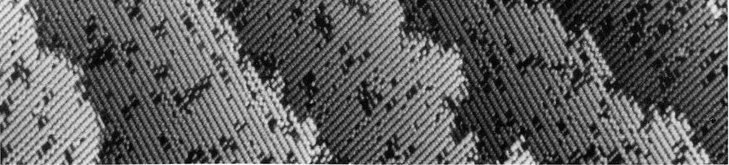
9 STM Images of Si(111)-(7 7) Empty-state image Filled-state image
10 Atomic Model of Si(111)-(7 7) Top view 26.9 A O 7.7 A o C C C E E E E C 112 E E C C Si adatom Si rest atom with a dangling bond Side view C E E C dangling bond 2nd layer rest atom faulted half unfaulted half

")
11 Atomic Structure of the Si(001) Surface

12 Atomic Structure of the Pt(001) Surface Surface Science 306, 10 (1994).

13 Si Magic Clusters Physical Review Letters 83, 120 (1999).
. Japanese Journal of Applied Physics 39, Part 1, No. 7A, 4100 (2000).")
14 Nucleation and Growth of Ge at Pb/Si(111) Physical Review Letters 83, 1191 (1999). Japanese Journal of Applied Physics 39, Part 1, No. 7A, 4100 (2000).


15 Ultra-High Vacuum Scanning Tunneling Microscope

16 Inchworm-Type Linear Motor
17 Piezoelectric Scanners Tripod scanner d 31 = S 1 /E 3, S 1 = δx/x, E 3 = V/z d 33 = S 3 /E 3, S 3 = δz/z Tube scanner
18 PZT Materials 1. The piezoelectric effect was discovered by Pierre Curie and Jacques Curie in The piezo materials used in STM are various kinds of lead zirconate titanate ceramics (PZT) --- a mixture of PbZrO 3 and PbTiO 3. It consists of small ferroelectric crystals in random orientations. 3. An advantage for PZT ceramics over single crystal materials is that it can be shaped easily and poled at a desired direction. 4. PZT scanners are widely used in SPM because they have excellent resolution in displacement, high stiffness, and fast response. A major drawback of PZT materials is its lack of accuracy due to many nonlinear characteristics, such as hysteresis, creep, and recoil-generated ringing, which often cause distortion in SPM images. The positioning error of a PZT scanner can be as much as 10-15% of the full scanning range. 5. The piezoelectric constants vary with temperature in a complicated manner, and also with the particular batch of materials by the manufacturer and time (the aging effect). 6. Displacement calibration or compensation is needed for accurate measurement of length or size.


19 Hysteresis of a PZT Actuator Hysteresis curves of an open-loop piezo actuator for various peak voltages Response of a PZT translator to a 1 V, 200 Hz triangular drive signal Creep of open-loop PZT motion

20 Topographic Images of AFM Square Grating Without correction With correction in the x-direction Jap. J. of Appl. Phys. 45, 3B,
21 Vibration Isolation Power spectra of a tunneling signal Vibration isolation Tunneling assembly Calculated transfer function
22 Vibration Isolation Requirement in vibrational noise: < 0.01Å in z, and < 0.1Å in x and y. 1. Building vibrations Hz. 2. Acoustic noise 10-10k Hz 3. Table/chamber resonances Hz 4. The design strategy is to reduce the resonance frequency of the vibration isolation system as low as possible, increase the resonance frequency of the tunneling assembly. 5. An effective way to damp the low-frequency vibrations is to suspend the microscope on long tension wires or levitate the table/chamber system on air legs. The performance can further be improved by increasing the mass of the system. 6. The microscope itself can be suspended with tension spring. 7. Vibrations in the medium-frequency can be damped by mounting the scanner assembly on a stack of materials of different elastic moduli or to suspend the scanner on tension springs with eddy current damping.


23 Tip Shape Effects


24 Si(111)-(7x7) Artifacts of the Tip Pb/Si(111)

25 Artifacts of the Tip
26 STM Feedback Control PID Control I Control Integrator I t G V I Error signal V I -V r G 1 G 1 (V I V r ) C High voltage amplifier V r R V Z A AV Z Z piezo ADC Computer
27 Theory of STM From one-dimensional tunneling problem tunneling current (ev<< φ ) 1 V A 2 I exp φ S S ( ev ) 1 2 A = A 0 1
28 I T S 2 e = h μν f Tunneling Current ( E )[ 1 f ( E + ev )] M δ ( E E ev ) π 2 μ ν μν μ ν where f (E) is Fermi function E is the energy of state μ,where μ and ν run over all the states of the μ M μν tip and surface, respectively. is tunneling matrix element M μν ( * ψ ψ ψ ) 2 h d s ψ μ ν ν μ * 2m where ψ μ is the wave function, and the integral is over any plane in the barrier region. I = I T I S S T 2 ( E) ρ ( E + ev ) M ( E) [ f ( E) f ( E + ev )] = A' ρ de T S ρ S ρ T where and are the densities of states in the sample and the tip, respectively.


29 Electronic Structures at Surfaces Not Tunneling Empty-State Imaging Tunneling Filled-State Imaging
30 I A' ρ T Tunneling Current 2 ( E) ρ ( E + ev ) M ( E) [ f ( E) f ( E + ev )] S Transmission probability of the electron 1 ( E ) = exp A φ S M 2 Usually, we assume ρ is featureless (ie. ρ const. T T ), and the sample electronic states dominate the tunnel spectra. de However, the tips might have effect on the tunnel spectra, if 1. we have atomically sharp tips,or 2. the tip has picked up a foreign atom.
31 Tunneling Barrier

32 In the low-voltage limit I Vρ ~ ; Case І -----metals where ρ ( ~ r ; E ) is the surface density of states of the sample at the center of the S t F tip( ), r~t ρ S S ( r E ) ρ ( E ) F is the density of states of the tip at the Fermi level and is often regarded as a constant. t ( ~ 2 r ; E) ψ ν ( ~ r ) δ ( E E) ρ t ( E F ) ν t F ν The contour followed by the tip is a contour of constant Fermi-level density of states of the sample, measured at the center of curvature of the tip.

33


34 Example -----Semiconductor 1.Tip-negative 2.Tip -positive Science 234, 304 (1986).
35 Scanning Tunneling Spectroscopy STM provides atomic-scale topographic information, and atomic-scale electronic information. However, the mixture of geometric and electronic structure information often complicates interpretation of observed feature. Several spectroscopic modes: 1. Voltage-dependent STM imaging. 2. Tunneling I-V curves, di/dv. Density of state (DOS) di/dv

36 Pb/Si(111) +1.8 V +2.4 V T 4 site V Filled-state Surface Science 257, 259 (1991)
37 Scanning Tunneling Spectroscopy (STS) 1. The tunneling transmission probablility T is a smooth, monotonically increasing function of V. Thus dt/dv contributes a smooth background. Therefore, structure in di/dv can usually be assigned to changes in the state density. 2. Extracting quantitative information about the sample density of states is difficult because the density of states of the tip and the tunneling transmission probability T are almost unknown. 3. Normalization of di/dv by I/V was proposed to minimize the distance dependence of the tunneling probability (or the voltage dependence of the tunneling barrier).


38 Single-Wall Carbon Nanotubes
 metallic, when n=3q semiconducting, otherwise 3.")
39 Electronic Structure of Single-Wall Nanotubes 1. Armchair nanotubes (n,n) metallic 2. Zigzag nanotubes (n,0) metallic, when n=3q semiconducting, otherwise 3. Chiral nanotubes (n,m) metallic, when m=n+3q
40 Electronic Structure of Single-wall Nanotubes Nature 391, 59 (1998).

 Xe on")
41 Atomic Manipulation with STM Nature 344, 524 (1990) Xe on a Ni surface
42

43 Quantum Correl M.F. Crommie et al., Science 262, 218 (1993).

44 Energy-Dependent Friedel Oscillations V t = + 10 mv V t = - 10 mv

45

")
46 Phys. Rev. Lett. 85, 2777 (2000)
. 2. I.-S. Hwang, R.-L. Lo, and T.T. Tsong, Surface Science 399, 173 (1998).")
47 Site Hopping of O 2 on Si(111)-7x7 O 2 molecule starts to hop between neighboring adatom sites at temperature about 300ºC. 1. I.-S. Hwang, R.-L. Lo, and T.T. Tsong, Physical Review Letters 78, 4797 (1997). 2. I.-S. Hwang, R.-L. Lo, and T.T. Tsong, Surface Science 399, 173 (1998).
48 Jumping rate R = N/t = R o exp(-e a /k B T) Arrhenius relation Arrhenius Plot for the Hopping from a Center Site to an Adjacent Center Site

49 Continuous-Time Scanning

50 Site Hopping of O 2 Molecule on Si(111)-(7x7) t = 0s t = 683s t = 730s t = 742s STM images B i I * * i I f B f Atomic model Si adatom Si rest atom Potential diagram ev B i ev ev I * * i I f B f I.-S. Hwang, et al., Phys. Rev. Lett. 78, 4797 (1997)
 Surfaces 480 Sample bias")
51 Silicon Magic Clusters on Si(111) Surfaces 480 Sample bias of 1.5V


52 Time interval 4.6 s Sample bias of 1.5V 450

53 The Decay Processes of 2D Islands 450Å 380Å Sample bias -2V 450

54 Decomposition of a Si Island into Magic Clusters Sample bias 1.5V 460


55
. 2. The magic number is estimated to be 9 to 15.")
56 Si Magic Clusters on Si(111)-(7 7) C E E C E C C E C E E C 1. The spacing between the protrusions is ~3.8Å, which is much larger than the Si-Si bond length (2.3Å). 2. The magic number is estimated to be 9 to 15. faulted half unfaulted half sample bias 1.5 V +1.8 V +1.2 V
 Type I 3 Sample bias : +2V Ref : PRL 90 (2003)")
57 Pb islands on Pb/Si(111) Deposit Pb on Pb/Si(111) at T~200K 3 ---Single thickness Type II IC phase(1) Type I 3 Sample bias : +2V Ref : PRL 90 (2003)

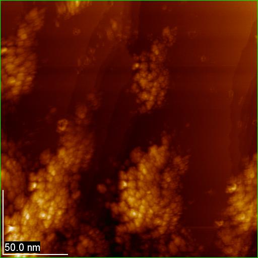
58 I 120K Two-dimensional Ag cluster arrays on quantum Pb islands 100nm x 170nm

59 Deposit Ag on Pb islands at T~175K

 37")
60 The size of the nanopucks (a) 37 Hex. 37

61 PRL 97, (2006) Size distribution of Ag nanopucks
62 Stability of Ag nanopucks

63
 1 1")
64 Reversible Surface Phase Transition Pb/Si(111)

65 Size Effects on the Pb-Covered Si Islands 200 K Scale bar: 5 nm 267 K I.S. Hwang, et al., Phys. Rev. Lett. 93, (2004)
66 Transition Temperature vs. Size 199 K


67 Temporal Fluctuations Near the Transition Temperature Slow scan direction Image size: 34 nm 38 nm 266 K

68 Slow scan direction


69 Temporal Fluctuations Near the Transition Temperature 260 K Image size: 40 nm 40 nm


70 Electrochemical Scanning Tunneling Microscopy Angew. Chem. Int. Ed. 40, 1162 (2001).
Scanning Tunneling Microscopy
 Scanning Tunneling Microscopy Scanning Direction References: Classical Tunneling Quantum Mechanics Tunneling current Tunneling current I t I t (V/d)exp(-Aφ 1/2 d) A = 1.025 (ev) -1/2 Å -1 I t = 10 pa~10na
Scanning Tunneling Microscopy
 Scanning Tunneling Microscopy References: 1. G. Binnig, H. Rohrer, C. Gerber, and Weibel, Phys. Rev. Lett. 49, 57 (1982); and ibid 50, 120 (1983). 2. J. Chen, Introduction to Scanning Tunneling Microscopy,
Scanning Tunneling Microscopy
 Scanning Tunneling Microscopy References: 1. G. Binnig, H. Rohrer, C. Gerber, and Weibel, Phys. Rev. Lett. 49, 57 (1982); and ibid 50, 120 (1983). 2. J. Chen, Introduction to Scanning Tunneling Microscopy,
Scanning Tunneling Microscopy
 Scanning Tunneling Microscopy A scanning tunneling microscope (STM) is an instrument for imaging surfaces at the atomic level. Its development in 1981 earned its inventors, Gerd Binnig and Heinrich Rohrer
Scanning Probe Microscopy (SPM)
") Scanning Probe Microscopy (SPM) Scanning Tunneling Microscopy (STM) --- G. Binnig, H. Rohrer et al, (1982) Near-Field Scanning Optical Microscopy (NSOM) --- D. W. Pohl (1982) Atomic Force Microscopy (AFM)
Scanning Probe Microscopy (SPM) Scanning Tunneling Microscopy (STM) --- G. Binnig, H. Rohrer et al, (1982) Near-Field Scanning Optical Microscopy (NSOM) --- D. W. Pohl (1982) Atomic Force Microscopy (AFM)
Scanning Probe Microscopy (SPM)
") CHEM53200: Lecture 9 Scanning Probe Microscopy (SPM) Major reference: 1. Scanning Probe Microscopy and Spectroscopy Edited by D. Bonnell (2001). 2. A practical guide to scanning probe microscopy by Park
CHEM53200: Lecture 9 Scanning Probe Microscopy (SPM) Major reference: 1. Scanning Probe Microscopy and Spectroscopy Edited by D. Bonnell (2001). 2. A practical guide to scanning probe microscopy by Park
Lecture 4 Scanning Probe Microscopy (SPM)
") Lecture 4 Scanning Probe Microscopy (SPM) General components of SPM; Tip --- the probe; Cantilever --- the indicator of the tip; Tip-sample interaction --- the feedback system; Scanner --- piezoelectric
Lecture 4 Scanning Probe Microscopy (SPM) General components of SPM; Tip --- the probe; Cantilever --- the indicator of the tip; Tip-sample interaction --- the feedback system; Scanner --- piezoelectric
The interpretation of STM images in light of Tersoff and Hamann tunneling model
 The interpretation of STM images in light of Tersoff and Hamann tunneling model The STM image represents contour maps of constant surface LDOS at E F, evaluated at the center of the curvature of the tip.
Instrumentation and Operation
 Instrumentation and Operation 1 STM Instrumentation COMPONENTS sharp metal tip scanning system and control electronics feedback electronics (keeps tunneling current constant) image processing system data
Spectroscopy at nanometer scale
 Spectroscopy at nanometer scale 1. Physics of the spectroscopies 2. Spectroscopies for the bulk materials 3. Experimental setups for the spectroscopies 4. Physics and Chemistry of nanomaterials Various
Scanning Probe Microscopy. EMSE-515 F. Ernst
 Scanning Probe Microscopy EMSE-515 F. Ernst 1 Literature 2 3 Scanning Probe Microscopy: The Lab on a Tip by Ernst Meyer,Ans Josef Hug,Roland Bennewitz 4 Scanning Probe Microscopy and Spectroscopy : Theory,
Program Operacyjny Kapitał Ludzki SCANNING PROBE TECHNIQUES - INTRODUCTION
 Program Operacyjny Kapitał Ludzki SCANNING PROBE TECHNIQUES - INTRODUCTION Peter Liljeroth Department of Applied Physics, Aalto University School of Science peter.liljeroth@aalto.fi Projekt współfinansowany
REPORT ON SCANNING TUNNELING MICROSCOPE. Course ME-228 Materials and Structural Property Correlations Course Instructor Prof. M. S.
 REPORT ON SCANNING TUNNELING MICROSCOPE Course ME-228 Materials and Structural Property Correlations Course Instructor Prof. M. S. Bobji Submitted by Ankush Kumar Jaiswal (09371) Abhay Nandan (09301) Sunil
Scanning Tunneling Microscopy. Wei-Bin Su, Institute of Physics, Academia Sinica
 Scanning Tunneling Microscopy Wei-Bin Su, Institute of Physics, Academia Sinica Tunneling effect Classical physics Field emission 1000 ~ 10000 V E V metal-vacuum-metal tunneling metal metal Quantum physics
Lecture 26 MNS 102: Techniques for Materials and Nano Sciences
 Lecture 26 MNS 102: Techniques for Materials and Nano Sciences Reference: #1 C. R. Brundle, C. A. Evans, S. Wilson, "Encyclopedia of Materials Characterization", Butterworth-Heinemann, Toronto (1992),
STM spectroscopy (STS)
") STM spectroscopy (STS) di dv 4 e ( E ev, r) ( E ) M S F T F Basic concepts of STS. With the feedback circuit open the variation of the tunneling current due to the application of a small oscillating voltage
STM spectroscopy (STS) di dv 4 e ( E ev, r) ( E ) M S F T F Basic concepts of STS. With the feedback circuit open the variation of the tunneling current due to the application of a small oscillating voltage
INTRODUCTION TO SCA\ \I\G TUNNELING MICROSCOPY
 INTRODUCTION TO SCA\ \I\G TUNNELING MICROSCOPY SECOND EDITION C. JULIAN CHEN Department of Applied Physics and Applied Mathematics, Columbia University, New York OXFORD UNIVERSITY PRESS Contents Preface
STM: Scanning Tunneling Microscope
 STM: Scanning Tunneling Microscope Basic idea STM working principle Schematic representation of the sample-tip tunnel barrier Assume tip and sample described by two infinite plate electrodes Φ t +Φ s =
Scanning Force Microscopy
 Scanning Force Microscopy Roland Bennewitz Rutherford Physics Building 405 Phone 398-3058 roland.bennewitz@mcgill.ca Scanning Probe is moved along scan lines over a sample surface 1 Force Microscopy Data
Scanning Probe Microscopy
 1 Scanning Probe Microscopy Dr. Benjamin Dwir Laboratory of Physics of Nanostructures (LPN) Benjamin.dwir@epfl.ch PH.D3.344 Outline: Introduction: What is SPM, history STM AFM Image treatment Advanced
Chapter 2 Scanning probes microscopes instrumentation. Chapter 2 Scanning probes microscopes instrumentation. 2.1: Tips. STM tips: requirements
 Chapter Objective: learn the general techniques that are essential for SPM. Chapter.1: Tips STM tips: requirements Geometry: Need for atomically-sharp apex for atomic resolution on a flat surface, rest
2) Atom manipulation. Xe / Ni(110) Model: Experiment:
 Atom manipulation. Xe / Ni(110) Model: Experiment:") 2) Atom manipulation D. Eigler & E. Schweizer, Nature 344, 524 (1990) Xe / Ni(110) Model: Experiment: G.Meyer, et al. Applied Physics A 68, 125 (1999) First the tip is approached close to the adsorbate
2) Atom manipulation D. Eigler & E. Schweizer, Nature 344, 524 (1990) Xe / Ni(110) Model: Experiment: G.Meyer, et al. Applied Physics A 68, 125 (1999) First the tip is approached close to the adsorbate
Scanning Probe Microscopy. Amanda MacMillan, Emmy Gebremichael, & John Shamblin Chem 243: Instrumental Analysis Dr. Robert Corn March 10, 2010
 Scanning Probe Microscopy Amanda MacMillan, Emmy Gebremichael, & John Shamblin Chem 243: Instrumental Analysis Dr. Robert Corn March 10, 2010 Scanning Probe Microscopy High-Resolution Surface Analysis
Experimental methods in physics. Local probe microscopies I
 Experimental methods in physics Local probe microscopies I Scanning tunnelling microscopy (STM) Jean-Marc Bonard Academic year 09-10 1. Scanning Tunneling Microscopy 1.1. Introduction Image of surface
Scanning Tunneling Microscopy. how does STM work? the quantum mechanical picture example of images how can we understand what we see?
 Scanning Tunneling Microscopy how does STM work? the quantum mechanical picture example of images how can we understand what we see? Observation of adatom diffusion with a field ion microscope Scanning
tip of a current tip and the sample. Components: 3. Coarse sample-to-tip isolation system, and
 SCANNING TUNNELING MICROSCOPE Brief history: Heinrich Rohrer and Gerd K. Binnig, scientists at IBM's Zurich Research Laboratory in Switzerland, are awarded the 1986 Nobel Prize in physicss for their work
Atomic and molecular interactions. Scanning probe microscopy.
 Atomic and molecular interactions. Scanning probe microscopy. Balázs Kiss Nanobiotechnology and Single Molecule Research Group, Department of Biophysics and Radiation Biology 27. November 2013. 2 Atomic
672 Advanced Solid State Physics. Scanning Tunneling Microscopy
 672 Advanced Solid State Physics Scanning Tunneling Microscopy Biao Hu Outline: 1. Introduction to STM 2. STM principle & working modes 3. STM application & extension 4. STM in our group 1. Introduction
Introduction to Scanning Tunneling Microscopy
 Introduction to Scanning Tunneling Microscopy C. JULIAN CHEN IBM Research Division Thomas J. Watson Research Center Yorktown Heights, New York New York Oxford OXFORD UNIVERSITY PRESS 1993 CONTENTS List
Scanning tunneling microscopy
 IFM The Department of Physics, Chemistry and Biology Lab 72 in TFFM08 Scanning tunneling microscopy NAME PERS. - NUMBER DATE APPROVED Rev. Dec 2006 Ivy Razado Aug 2014 Tuomas Hänninen Contents 1 Introduction
3.1 Electron tunneling theory
 Scanning Tunneling Microscope (STM) was invented in the 80s by two physicists: G. Binnig and H. Rorher. They got the Nobel Prize a few years later. This invention paved the way for new possibilities in
Local spectroscopy. N. Witkowski W. Sacks
 Local spectroscopy N. Witkowski W. Sacks Outlook 1. STM/STS theory elements a. history of STM and basic idea b. tunnel effect c. STM/STS 2. Technology a. STM design : vibration and thermal drift b. STM
SCANNING-PROBE TECHNIQUES OR APPARATUS; APPLICATIONS OF SCANNING-PROBE TECHNIQUES, e.g. SCANNING PROBE MICROSCOPY [SPM]
![SCANNING-PROBE TECHNIQUES OR APPARATUS; APPLICATIONS OF SCANNING-PROBE TECHNIQUES, e.g. SCANNING PROBE MICROSCOPY [SPM]](/thumbs/81/83165631.jpg "SCANNING-PROBE TECHNIQUES OR APPARATUS; APPLICATIONS OF SCANNING-PROBE TECHNIQUES, e.g. SCANNING PROBE MICROSCOPY [SPM]") G01Q SCANNING-PROBE TECHNIQUES OR APPARATUS; APPLICATIONS OF SCANNING-PROBE TECHNIQUES, e.g. SCANNING PROBE MICROSCOPY [SPM] Scanning probes, i.e. devices having at least a tip of nanometre sized dimensions
G01Q SCANNING-PROBE TECHNIQUES OR APPARATUS; APPLICATIONS OF SCANNING-PROBE TECHNIQUES, e.g. SCANNING PROBE MICROSCOPY [SPM] Scanning probes, i.e. devices having at least a tip of nanometre sized dimensions
Scanning Tunneling Microscopy
 Scanning Tunneling Microscopy References: 1. G. Binnig, H. Rohrer, C. Gerber, and Weibel, Phys. Rev. Lett. 49, 57 (1982); and ibid 50, 120 (1983). 2. J. Chen, Introduction to Scanning Tunneling Microscopy,
Contents. What is AFM? History Basic principles and devices Operating modes Application areas Advantages and disadvantages
 Contents What is AFM? History Basic principles and devices Operating modes Application areas Advantages and disadvantages Figure1: 2004 Seth Copen Goldstein What is AFM? A type of Scanning Probe Microscopy
Module 26: Atomic Force Microscopy. Lecture 40: Atomic Force Microscopy 3: Additional Modes of AFM
 Module 26: Atomic Force Microscopy Lecture 40: Atomic Force Microscopy 3: Additional Modes of AFM 1 The AFM apart from generating the information about the topography of the sample features can be used
Introduction to Scanning Probe Microscopy
 WORKSHOP Nanoscience on the Tip Introduction to Scanning Probe Microscopy Table of Contents: 1 Historic Perspectives... 1 2 Scanning Force Microscopy (SFM)... 2 2.1. Contact Mode... 2 2.2. AC Mode Imaging...
Scanning Probe Microscopy (SPM)
") http://ww2.sljus.lu.se/staff/rainer/spm.htm Scanning Probe Microscopy (FYST42 / FAFN30) Scanning Probe Microscopy (SPM) overview & general principles March 23 th, 2018 Jan Knudsen, room K522, jan.knudsen@sljus.lu.se
http://ww2.sljus.lu.se/staff/rainer/spm.htm Scanning Probe Microscopy (FYST42 / FAFN30) Scanning Probe Microscopy (SPM) overview & general principles March 23 th, 2018 Jan Knudsen, room K522, jan.knudsen@sljus.lu.se
Basic Laboratory. Materials Science and Engineering. Atomic Force Microscopy (AFM)
") Basic Laboratory Materials Science and Engineering Atomic Force Microscopy (AFM) M108 Stand: 20.10.2015 Aim: Presentation of an application of the AFM for studying surface morphology. Inhalt 1.Introduction...
Basic Laboratory Materials Science and Engineering Atomic Force Microscopy (AFM) M108 Stand: 20.10.2015 Aim: Presentation of an application of the AFM for studying surface morphology. Inhalt 1.Introduction...
Final exam. Introduction to Nanotechnology. Name: Student number:
 1 Final exam. Introduction to Nanotechnology Name: Student number: 1. (a) What is the definition for a cluster size-wise? (3%) (b) Calculate the energy separation near the Fermi surface of a metallic cluster
Atomic Force Microscopy imaging and beyond
 Atomic Force Microscopy imaging and beyond Arif Mumtaz Magnetism and Magnetic Materials Group Department of Physics, QAU Coworkers: Prof. Dr. S.K.Hasanain M. Tariq Khan Alam Imaging and beyond Scanning
Intermittent-Contact Mode Force Microscopy & Electrostatic Force Microscopy (EFM)
") WORKSHOP Nanoscience on the Tip Intermittent-Contact Mode Force Microscopy & Electrostatic Force Microscopy (EFM) Table of Contents: 1. Motivation... 1. Simple Harmonic Motion... 1 3. AC-Mode Imaging...
WORKSHOP Nanoscience on the Tip Intermittent-Contact Mode Force Microscopy & Electrostatic Force Microscopy (EFM) Table of Contents: 1. Motivation... 1. Simple Harmonic Motion... 1 3. AC-Mode Imaging...
NIS: what can it be used for?
 AFM @ NIS: what can it be used for? Chiara Manfredotti 011 670 8382/8388/7879 chiara.manfredotti@to.infn.it Skype: khiaram 1 AFM: block scheme In an Atomic Force Microscope (AFM) a micrometric tip attached
Probing Molecular Electronics with Scanning Probe Microscopy
 Probing Molecular Electronics with Scanning Probe Microscopy Mark C. Hersam Assistant Professor Department of Materials Science and Engineering, Northwestern University, Evanston, IL 60208-3108 Ph: 847-491-2696,
IMAGING TECHNIQUES IN CONDENSED MATTER PHYSICS SCANNING TUNNELING AND ATOMIC FORCE MICROSCOPES
 1 IMAGING TECHNIQUES IN CONDENSED MATTER PHYSICS SCANNING TUNNELING AND ATOMIC FORCE MICROSCOPES 2 WHY THIS TOPIC? STM and AFM images are ubiquitous in condensed matter physics. It is important to understand
Physics at the Nanoscale and applica1ons. Phelma / Grenoble INP and Ins1tut Néel / CNRS
 Physics at the Nanoscale and applica1ons Clemens.Winkelmann@grenoble.cnrs.fr Phelma / Grenoble INP and Ins1tut Néel / CNRS Physics at the Nanoscale I Basics of quantum mechanics II Sta1s1cal Physics III
Chapter 5 Nanomanipulation. Chapter 5 Nanomanipulation. 5.1: With a nanotube. Cutting a nanotube. Moving a nanotube
 Objective: learn about nano-manipulation techniques with a STM or an AFM. 5.1: With a nanotube Moving a nanotube Cutting a nanotube Images at large distance At small distance : push the NT Voltage pulse
Introduction to Scanning Probe Microscopy Zhe Fei
 Introduction to Scanning Probe Microscopy Zhe Fei Phys 590B, Apr. 2019 1 Outline Part 1 SPM Overview Part 2 Scanning tunneling microscopy Part 3 Atomic force microscopy Part 4 Electric & Magnetic force
Electron confinement in metallic nanostructures
 Electron confinement in metallic nanostructures Pierre Mallet LEPES-CNRS associated with Joseph Fourier University Grenoble (France) Co-workers : Jean-Yves Veuillen, Stéphane Pons http://lepes.polycnrs-gre.fr/
The basics of Scanning Probe Microscopy
 McGill University, Montreal, Jan. 8 th 2009 The basics of Scanning Probe Microscopy Federico Rosei Canada Research Chair in Nanostructured Organic and Inorganic Materials Énergie, Matériaux et Télécommunications,
AFM for Measuring Surface Topography and Forces
 ENB 2007 07.03.2007 AFM for Measuring Surface Topography and Forces Andreas Fery Scanning Probe : What is it and why do we need it? AFM as a versatile tool for local analysis and manipulation Dates Course
Spectroscopy of Nanostructures. Angle-resolved Photoemission (ARPES, UPS)
") Spectroscopy of Nanostructures Angle-resolved Photoemission (ARPES, UPS) Measures all quantum numbers of an electron in a solid. E, k x,y, z, point group, spin E kin, ϑ,ϕ, hν, polarization, spin Electron
Spectroscopy of Nanostructures Angle-resolved Photoemission (ARPES, UPS) Measures all quantum numbers of an electron in a solid. E, k x,y, z, point group, spin E kin, ϑ,ϕ, hν, polarization, spin Electron
Santosh Devasia Mechanical Eng. Dept., UW
 Nano-positioning Santosh Devasia Mechanical Eng. Dept., UW http://faculty.washington.edu/devasia/ Outline of Talk 1. Why Nano-positioning 2. Sensors for Nano-positioning 3. Actuators for Nano-positioning
Dopant Concentration Measurements by Scanning Force Microscopy
 73.40L Scanning Microsc. Microanal. Microstruct. 551 Classification Physics Abstracts - - 61.16P 73.00 Dopant Concentration Measurements by Scanning Force Microscopy via p-n Junctions Stray Fields Jacopo
Microscopical and Microanalytical Methods (NANO3)
") Microscopical and Microanalytical Methods (NANO3) 06.11.15 10:15-12:00 Introduction - SPM methods 13.11.15 10:15-12:00 STM 20.11.15 10:15-12:00 STS Erik Zupanič erik.zupanic@ijs.si stm.ijs.si 27.11.15
Microscopical and Microanalytical Methods (NANO3) 06.11.15 10:15-12:00 Introduction - SPM methods 13.11.15 10:15-12:00 STM 20.11.15 10:15-12:00 STS Erik Zupanič erik.zupanic@ijs.si stm.ijs.si 27.11.15
Spectroscopies for Unoccupied States = Electrons
 Spectroscopies for Unoccupied States = Electrons Photoemission 1 Hole Inverse Photoemission 1 Electron Tunneling Spectroscopy 1 Electron/Hole Emission 1 Hole Absorption Will be discussed with core levels
Application of single crystalline tungsten for fabrication of high resolution STM probes with controlled structure 1
 Application of single crystalline tungsten for fabrication of high resolution STM probes with controlled structure 1 A. N. Chaika a, S. S. Nazin a, V. N. Semenov a, V. G. Glebovskiy a, S. I. Bozhko a,b,
Spectroscopy at nanometer scale
 Spectroscopy at nanometer scale 1. Physics of the spectroscopies 2. Spectroscopies for the bulk materials 3. Experimental setups for the spectroscopies 4. Physics and Chemistry of nanomaterials Various
General concept and defining characteristics of AFM. Dina Kudasheva Advisor: Prof. Mary K. Cowman
 General concept and defining characteristics of AFM Dina Kudasheva Advisor: Prof. Mary K. Cowman Overview Introduction History of the SPM invention Technical Capabilities Principles of operation Examples
Scanning Force Microscopy II
 Scanning Force Microscopy II Measurement modes Magnetic force microscopy Artifacts Lars Johansson 1 SFM - Forces Chemical forces (short range) Van der Waals forces Electrostatic forces (long range) Capillary
Outline Scanning Probe Microscope (SPM)
") AFM Outline Scanning Probe Microscope (SPM) A family of microscopy forms where a sharp probe is scanned across a surface and some tip/sample interactions are monitored Scanning Tunneling Microscopy (STM)
AFM Outline Scanning Probe Microscope (SPM) A family of microscopy forms where a sharp probe is scanned across a surface and some tip/sample interactions are monitored Scanning Tunneling Microscopy (STM)
Characterization of MEMS Devices
 MEMS: Characterization Characterization of MEMS Devices Prasanna S. Gandhi Assistant Professor, Department of Mechanical Engineering, Indian Institute of Technology, Bombay, Recap Characterization of MEMS
Control of Dynamics of SPM Probes for Non-destructive Defectoscopy
 XXX. ASR '2005 Seminar, Instruments and Control, Ostrava, April 29, 2005 209 Control of Dynamics of SPM Probes for Non-destructive Defectoscopy KALA, Jaroslav Ing., Physics Department, FEEC, BUT, Technická
single-electron electron tunneling (SET)
") single-electron electron tunneling (SET) classical dots (SET islands): level spacing is NOT important; only the charging energy (=classical effect, many electrons on the island) quantum dots: : level spacing
single-electron electron tunneling (SET) classical dots (SET islands): level spacing is NOT important; only the charging energy (=classical effect, many electrons on the island) quantum dots: : level spacing
Scanning Probe Microscopies (SPM)
") Scanning Probe Microscopies (SPM) Nanoscale resolution af objects at solid surfaces can be reached with scanning probe microscopes. They allow to record an image of the surface atomic arrangement in direct
Scanning Probe Microscopies (SPM) Nanoscale resolution af objects at solid surfaces can be reached with scanning probe microscopes. They allow to record an image of the surface atomic arrangement in direct
Microscopie a stilo: principi ed esempi di applicazione
 Microscopie a stilo: principi ed esempi di applicazione Adele Sassella Dipartimento di Scienza dei Materiali Università degli Studi di Milano Bicocca adele.sassella@unimib.it Pavia, 22 aprile 2009 SCANNING
Citation for published version (APA): Mendoza, S. M. (2007). Exploiting molecular machines on surfaces s.n.
: Mendoza, S. M. (2007). Exploiting molecular machines on surfaces s.n.") University of Groningen Exploiting molecular machines on surfaces Mendoza, Sandra M IMPORTANT NOTE: You are advised to consult the publisher's version (publisher's PDF) if you wish to cite from it. Please
University of Groningen Exploiting molecular machines on surfaces Mendoza, Sandra M IMPORTANT NOTE: You are advised to consult the publisher's version (publisher's PDF) if you wish to cite from it. Please
Quantized Electrical Conductance of Carbon nanotubes(cnts)
") Quantized Electrical Conductance of Carbon nanotubes(cnts) By Boxiao Chen PH 464: Applied Optics Instructor: Andres L arosa Abstract One of the main factors that impacts the efficiency of solar cells is
Quantized Electrical Conductance of Carbon nanotubes(cnts) By Boxiao Chen PH 464: Applied Optics Instructor: Andres L arosa Abstract One of the main factors that impacts the efficiency of solar cells is
Scanning Tunneling Microscopy/Spectroscopy
 Scanning Tunneling Microscopy/Spectroscopy 0 Scanning Tunneling Microscope 1 Scanning Tunneling Microscope 2 Scanning Tunneling Microscope 3 Typical STM talk or paper... The differential conductance di/dv
Scanning Tunneling Microscopy and its Application
 Chunli Bai Scanning Tunneling Microscopy and its Application With 181 Figures SHANGHAI SCIENTIFIC & TECHNICAL PUBLISHERS Jpl Springer Contents 1. Introduction 1 1.1 Advantages of STM Compared with Other
Scanning Tunneling Microscopy Transmission Electron Microscopy
 Scanning Tunneling Microscopy Transmission Electron Microscopy Speakers Burcu Başar Semih Gezgin Yavuz Selim Telis Place Hacettepe University Department of Chemical Engineering It s a small world after
Quantum Condensed Matter Physics Lecture 12
 Quantum Condensed Matter Physics Lecture 12 David Ritchie QCMP Lent/Easter 2016 http://www.sp.phy.cam.ac.uk/drp2/home 12.1 QCMP Course Contents 1. Classical models for electrons in solids 2. Sommerfeld
And Manipulation by Scanning Probe Microscope
 Basic 15 Nanometer Scale Measurement And Manipulation by Scanning Probe Microscope Prof. K. Fukuzawa Dept. of Micro/Nano Systems Engineering Nagoya University I. Basics of scanning probe microscope Basic
Microscopy and Spectroscopy with Tunneling Electrons STM. Sfb Kolloquium 23rd October 2007
 Microscopy and Spectroscopy with Tunneling Electrons STM Sfb Kolloquium 23rd October 2007 The Tunnel effect T ( E) exp( S Φ E ) Barrier width s Barrier heigth Development: The Inventors 1981 Development:
MS482 Materials Characterization ( 재료분석 ) Lecture Note 11: Scanning Probe Microscopy. Byungha Shin Dept. of MSE, KAIST
 Lecture Note 11: Scanning Probe Microscopy. Byungha Shin Dept. of MSE, KAIST") 2015 Fall Semester MS482 Materials Characterization ( 재료분석 ) Lecture Note 11: Scanning Probe Microscopy Byungha Shin Dept. of MSE, KAIST 1 Course Information Syllabus 1. Overview of various characterization
2015 Fall Semester MS482 Materials Characterization ( 재료분석 ) Lecture Note 11: Scanning Probe Microscopy Byungha Shin Dept. of MSE, KAIST 1 Course Information Syllabus 1. Overview of various characterization
Pb thin films on Si(111): Local density of states and defects
: Local density of states and defects") University of Wollongong Research Online Australian Institute for Innovative Materials - Papers Australian Institute for Innovative Materials 2014 Pb thin films on Si(111): Local density of states and
University of Wollongong Research Online Australian Institute for Innovative Materials - Papers Australian Institute for Innovative Materials 2014 Pb thin films on Si(111): Local density of states and
SUPPLEMENTARY NOTES Supplementary Note 1: Fabrication of Scanning Thermal Microscopy Probes
 SUPPLEMENTARY NOTES Supplementary Note 1: Fabrication of Scanning Thermal Microscopy Probes Fabrication of the scanning thermal microscopy (SThM) probes is summarized in Supplementary Fig. 1 and proceeds
New open-loop actuating method of piezoelectric actuators for removing hysteresis and creep
 REVIEW OF SCIENTIFIC INSTRUMENTS VOLUME 71, NUMBER 9 SEPTEMBER 2000 New open-loop actuating method of piezoelectric actuators for removing hysteresis and creep Hewon Jung, Jong Youp Shim, and DaeGab Gweon
CNPEM Laboratório de Ciência de Superfícies
 Investigating electrical charged samples by scanning probe microscopy: the influence to magnetic force microscopy and atomic force microscopy phase images. Carlos A. R. Costa, 1 Evandro M. Lanzoni, 1 Maria
Application of electrostatic force microscopy in nanosystem diagnostics
 Materials Science, Vol., No. 3, 003 Application of electrostatic force microscopy in nanosystem diagnostics TEODOR P. GOTSZALK *, PIOTR GRABIEC, IVO W. RANGELOW 3 Fulty of Microsystem Electronics and Photonics,
Nanostructure. Materials Growth Characterization Fabrication. More see Waser, chapter 2
 Nanostructure Materials Growth Characterization Fabrication More see Waser, chapter 2 Materials growth - deposition deposition gas solid Physical Vapor Deposition Chemical Vapor Deposition Physical Vapor
Scanning Tunneling Microscopy: theory and examples
 Scanning Tunneling Microscopy: theory and examples Jan Knudsen The MAX IV laboratory & Division of synchrotron radiation research K5-53 (Sljus) jan.knudsen@sljus.lu.se April 17, 018 http://www.sljus.lu.se/staff/rainer/spm.htm
Reducing dimension. Crystalline structures
 Reducing dimension 2D surfaces, interfaces and quantum wells 1D carbon nanotubes, quantum wires and conducting polymers 0D nanocrystals, nanoparticles, lithographically patterned quantum dots Crystalline
Digital Instruments (DI) Multymode Nanoscope IIIa
 Multymode Nanoscope IIIa") Lecture 6 From Microsystems to the Nanoworld Freiburger Materialforschungszentrum Institut für Mikrosystemtechnik Basics of AFM AFM provides very hogh resolution images of various sample properties PSD
Lecture 6 From Microsystems to the Nanoworld Freiburger Materialforschungszentrum Institut für Mikrosystemtechnik Basics of AFM AFM provides very hogh resolution images of various sample properties PSD
Atomic Force Microscopy (AFM) Part I
 Part I") Atomic Force Microscopy (AFM) Part I CHEM-L2000 Eero Kontturi 6 th March 2018 Lectures on AFM Part I Principles and practice Imaging of native materials, including nanocellulose Part II Surface force measurements
Atomic Force Microscopy (AFM) Part I CHEM-L2000 Eero Kontturi 6 th March 2018 Lectures on AFM Part I Principles and practice Imaging of native materials, including nanocellulose Part II Surface force measurements
Surface Studies by Scanning Tunneling Microscopy
 Surface Studies by Scanning Tunneling Microscopy G. Binnig, H. Rohrer, Ch. Gerber, and E. Weibel IBM Zurich Research Laboratory, 8803 Ruschlikon-ZH, Switzerland (Received by Phys. Rev. Lett. on 30th April,
Chapter 10. Nanometrology. Oxford University Press All rights reserved.
 Chapter 10 Nanometrology Oxford University Press 2013. All rights reserved. 1 Introduction Nanometrology is the science of measurement at the nanoscale level. Figure illustrates where nanoscale stands
Introduction to the Scanning Tunneling Microscope
 Introduction to the Scanning Tunneling Microscope A.C. Perrella M.J. Plisch Center for Nanoscale Systems Cornell University, Ithaca NY Measurement I. Theory of Operation The scanning tunneling microscope
Piezoactuators. Jiří Tůma
 Piezoactuators Jiří Tůma 1 Domain Piezoelectric effect Direct piezoelectric effect discovered the brothers Pierre and Jacques Curie. They found that certain crystalline materials (ceramics) having the
Scanning capacitance spectroscopy of an Al x Ga 1Àx NÕGaN heterostructure field-effect transistor structure: Analysis of probe tip effects
 Scanning capacitance spectroscopy of an Al x Ga 1Àx NÕGaN heterostructure field-effect transistor structure: Analysis of probe tip effects D. M. Schaadt and E. T. Yu a) Department of Electrical and Computer
Single-Molecule Recognition and Manipulation Studied by Scanning Probe Microscopy
 Single-Molecule Recognition and Manipulation Studied by Scanning Probe Microscopy Byung Kim Department of Physics Boise State University Langmuir (in press, 2006) swollen collapsed Hydrophilic non-sticky
High resolution STM imaging with oriented single crystalline tips
 High resolution STM imaging with oriented single crystalline tips A. N. Chaika a, *, S. S. Nazin a, V. N. Semenov a, N. N Orlova a, S. I. Bozhko a,b, O. Lübben b, S. A. Krasnikov b, K. Radican b, and I.
Scanning Tunneling Microscopy Studies of the Ge(111) Surface
 Surface") VC Scanning Tunneling Microscopy Studies of the Ge(111) Surface Anna Rosen University of California, Berkeley Advisor: Dr. Shirley Chiang University of California, Davis August 24, 2007 Abstract: This
VC Scanning Tunneling Microscopy Studies of the Ge(111) Surface Anna Rosen University of California, Berkeley Advisor: Dr. Shirley Chiang University of California, Davis August 24, 2007 Abstract: This
Scanning Force Microscopy And Related Techniques. With the help of.
 With the help of. 1. Yosi Shacham TAU 2. Yossi Rosenwacks TAU 3. Julio Gomez-Herrero UAM 4. Adriana Gil - UAM 5. Serge Lemay - Delft 6. Hezy Cohen - HUJI 7. Scanning Force Microscopy And Related Techniques
Supporting Information
 Supporting Information Spatially-resolved imaging on photocarrier generations and band alignments at perovskite/pbi2 hetero-interfaces of perovskite solar cells by light-modulated scanning tunneling microscopy
Theoretical Modelling and the Scanning Tunnelling Microscope
 Theoretical Modelling and the Scanning Tunnelling Microscope Rubén Pérez Departamento de Física Teórica de la Materia Condensada Universidad Autónoma de Madrid Curso Introducción a la Nanotecnología Máster
Scanning Force Microscopy And Related Techniques
 Scanning Force Microscopy And Related Techniques Danny Porath 2003 With the help of. 1. Yosi Shacham TAU 2. Yossi Rosenwacks TAU 3. Julio Gomez-Herrero UAM 4. Adriana Gil - UAM 5. Serge Lemay - Delft 6.
Integrating MEMS Electro-Static Driven Micro-Probe and Laser Doppler Vibrometer for Non-Contact Vibration Mode SPM System Design
 Tamkang Journal of Science and Engineering, Vol. 12, No. 4, pp. 399 407 (2009) 399 Integrating MEMS Electro-Static Driven Micro-Probe and Laser Doppler Vibrometer for Non-Contact Vibration Mode SPM System
Measurement of hardness, surface potential, and charge distribution with dynamic contact mode electrostatic force microscope
 REVIEW OF SCIENTIFIC INSTRUMENTS VOLUME 70, NUMBER 3 MARCH 1999 Measurement of hardness, surface potential, and charge distribution with dynamic contact mode electrostatic force microscope J. W. Hong,
Ecole Franco-Roumaine : Magnétisme des systèmes nanoscopiques et structures hybrides - Brasov, Modern Analytical Microscopic Tools
 1. Introduction Solid Surfaces Analysis Group, Institute of Physics, Chemnitz University of Technology, Germany 2. Limitations of Conventional Optical Microscopy 3. Electron Microscopies Transmission Electron