December 13, Washington County Public Works Department Myeron Road North Stillwater, MN Attn: Mr. Andrew Giesen
|
|
|
- Eric Ward
- 5 years ago
- Views:
Transcription

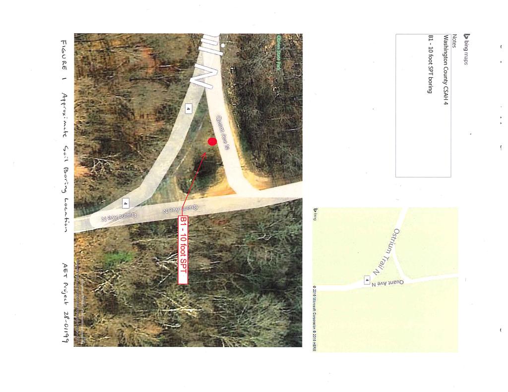
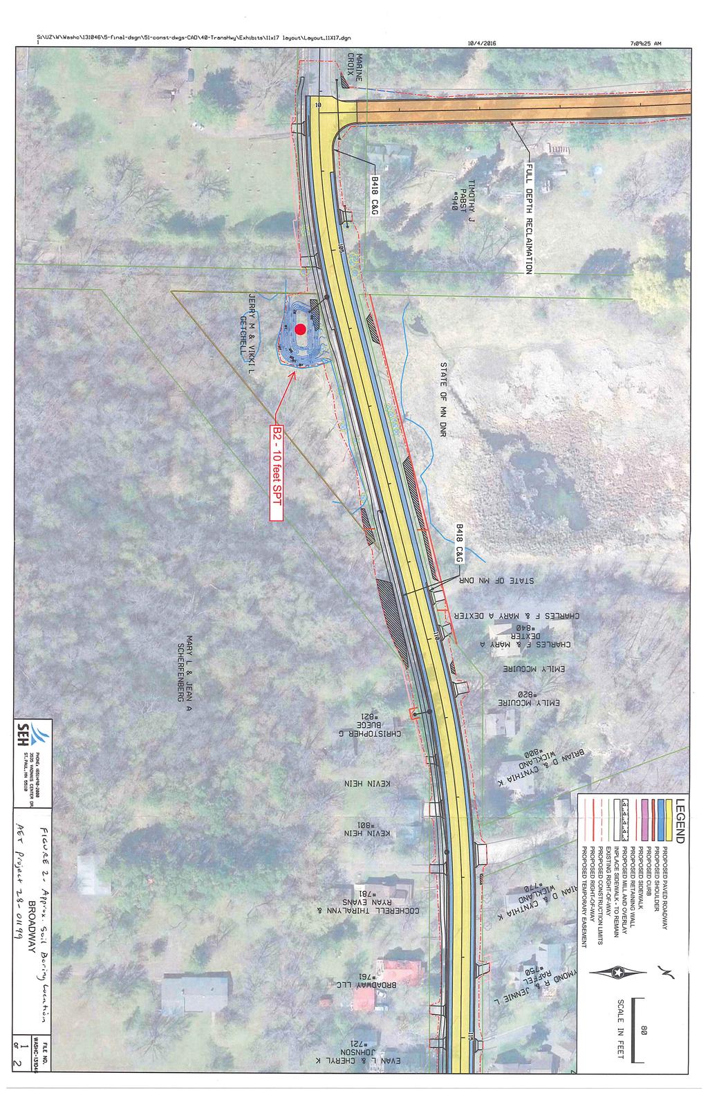
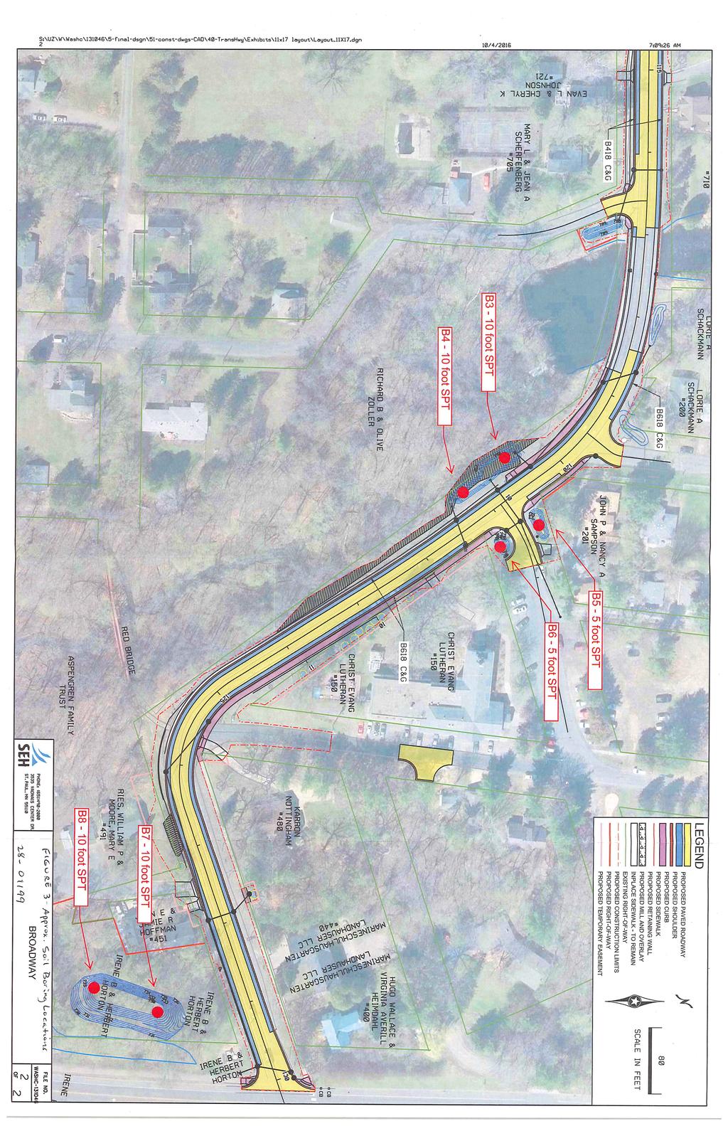
1 CONSULTANTS ENVIRONMENTAL GEOTECHNICAL MATERIALS FORENSICS December 13, 2016 Washington County Public Works Department Myeron Road North Stillwater, MN Attn: Mr. Andrew Giesen RE: Geotechnical Services CSAH 4 from State Hwy 95 to Quant Avenue Marine on St. Croix, Minnesota AET Project Dear Mr. Giesen: This letter report presents the results of our geotechnical exploration for the planned water resources improvements at County State Aid Highway (CSAH) 4 between Hwy 95 and Quant Avenue near Marine on St. Croix, Minnesota. The work was performed per our proposal to SEH dated October 17, 2017, and our annual contract with Washington County #9773. The proposal was authorized by you by on November 9, The authorized scope includes the following: Drill and sample eight (8) standard penetration test borings to depths of 6 feet to 10 feet. Prepare this report, including logs of the test borings, descriptions of the drilling, sampling, testing and classification methods, and a review of the in-place soil and ground water conditions encountered. Site Exploration and Testing Soil Borings We performed eight (8) standard penetration test borings on November 24, The logs of the test borings are attached. The boring locations appear on attached Figures 1-3. The boring locations were chosen and surveyed by SEH. The boring logs contain information concerning soil layering, soil classification, geologic description, and moisture condition. Relative density or consistency is also noted, which is based on the standard penetration resistance (N-value). 550 Cleveland Avenue North Saint Paul, MN Phone (651) (800) Fax (651) AA/EEO This document shall not be reproduced, except in full, without written approval from American Engineering Testing, Inc.
2 Washington County CSAH 4 Water Resources Borings Report No December 13, 2016 Page 2 of 3 We refer you to the standard sheet entitled Exploration/Classification Methods for details on the drilling and sampling methods, the classification methods, and the water level measurement methods. Data sheets concerning the Unified Soil Classification System, the AASHTO Soil Classification System, the descriptive terminology, and the symbols used on the boring logs are also attached. Laboratory Testing The laboratory test program consisted of numerous water content tests. The test results appear on the individual boring logs adjacent to the samples upon which they were performed. Conditions Encountered Subgrade Soils Each of the borings encountered fill soils at the surface and extending to depths of 1.5 to 6 feet. The fill soils are highly variable consisting of sandy lean clay, slightly organic sandy lean clay, gravelly clayey sand, and silty sand. Topsoil, consisting of slightly organic sandy lean clay and clayey sand with organic fines, was encountered at Borings 2 and 8. At Boring 2, the thickness of topsoil was 0.5 feet and it was encountered at 1 foot below the surface. At Boring 8, the thickness of topsoil was 2 feet and it was encountered at 3.5 feet below the surface. The natural soils below the fill and/or topsoil is predominantly coarse alluvial, classified generally as silty sand with varying amounts of gravel, and some sand with silt. The exception to this is Boring 2 where clayey sand glacial till were present above the coarse alluvium. Borings 1, 3, 4, 7, and 8 encountered weathered bedrock at depths ranging from 4.5 to 8.5 feet from the surface. Ground Water Water levels appeared in three boreholes, 5.2, 5.4, and 4.6 feet deep at Borings 2, 7, and 8, respectively. Limitations Within the limitations of scope, budget, and schedule, our services have been conducted according to generally accepted geotechnical engineering practices at this time and location. Other than this, no warranty, express or implied, is intended.
3 Washington County CSAH 4 Water Resources Borings Report No December 13, 2016 Page 3 of 3 Important information regarding risk management and proper use of this report is given in the attached sheet entitled Geotechnical Report Limitations and Guidelines for Use. The samples will be saved for one month beyond the date of this report. If you have questions regarding this report or if we can be of further assistance, please contact me. Sincerely, American Engineering Testing, Inc. Reviewed by: American Engineering Testing, Inc. Melanie Fiegen, PE Senior Engineer MN License #16711 Phone: (651) mfiegen@amengtest.com Chunhua Han, PE Principal Engineer cc: Mr. Luke Thompson/SEH, lthompson@sehinc.com Attachments Figure 1 Boring Location, Boring 1 Figure 2 Boring Location, Boring 2 Figure 3 Boring Locations, Borings 3 to 8 Subsurface Boring Logs Exploration/Classification Methods Boring Log Notes Unified Soil Classification System AASHTO Soil Classification System Geotechnical Report Limitations and Guidelines for Use
4
5
6
7
8
9
10
11
12
13
14
15 SAMPLING METHODS EXPLORATION/CLASSIFICATION METHODS Split-Spoon Samples (SS) Standard penetration (split-spoon) samples were collected in general accordance with ASTM:D1586. This method consists of driving a 2" O.D. split barrel sampler into the in-situ soil with a 140-pound hammer dropped from a height of 30". The sampler is driven a total of 18" into the soil. After an initial set of 6", the number of hammer blows to drive the sampler the final 12" is known as the standard penetration resistance or N-value. Disturbed Samples (DS)/Spin-up Samples (SU) Sample types described as DS or SU on the boring logs are disturbed samples, which are taken from the flights of the auger. Because the auger disturbs the samples, possible soil layering and contact depths should be considered approximate. Sampling Limitations Unless actually observed in a sample, contacts between soil layers are estimated based on the spacing of samples and the action of drilling tools. Cobbles, boulders, and other large objects generally cannot be recovered from test borings, and they may be present in the ground even if they are not noted on the boring logs. CLASSIFICATION METHODS Soil classifications shown on the boring logs are based on the Unified Soil Classification (USC) system. The USC system is described in ASTM:D2487 and D2488. Where laboratory classification tests (sieve analysis or Atterberg Limits) have been performed, accurate classifications per ASTM: D2487 are possible. Otherwise, soil classifications shown on the boring logs are visual-manual judgments. Charts are attached which provide information on the USC system, the descriptive terminology, and the symbols used on the boring logs. The boring logs include descriptions of apparent geology. The geologic depositional origin of each soil layer is interpreted primarily by observation of the soil samples, which can be limited. Observations of the surrounding topography, vegetation, and development can sometimes aid this judgment. WATER LEVEL MEASUREMENTS The ground water level measurements are shown at the bottom of the boring logs. The following information appears under Water Level Measurements on the logs: Date and Time of measurement Sampled Depth: lowest depth of soil sampling at the time of measurement Casing Depth: depth to bottom of casing or hollow-stem auger at time of measurement Cave-in Depth: depth at which measuring tape stops in the borehole Water Level: depth in the borehole where free water is encountered Drilling Fluid Level: same as Water Level, except that the liquid in the borehole is drilling fluid The true location of the water table at the boring locations may be different than the water levels measured in the boreholes. This is possible because there are several factors that can affect the water level measurements in the borehole. Some of these factors include: permeability of each soil layer in profile, presence of perched water, amount of time between water level readings, presence of drilling fluid, weather conditions, and use of borehole casing. SAMPLE STORAGE Unless notified to do otherwise, we routinely retain representative samples of the soils recovered from the borings for a period of 30 days. 01REP051 (12/08) AMERICAN ENGINEERING TESTING, INC.
16 BORING LOG NOTES DRILLING AND SAMPLING SYMBOLS TEST SYMBOLS Symbol Definition Symbol Definition B, H, N: Size of flush-joint casing CA: Crew Assistant (initials) CAS: Pipe casing, number indicates nominal diameter in inches CC: Crew Chief (initials) COT: Clean-out tube DC: Drive casing; number indicates diameter in inches DM: Drilling mud or bentonite slurry DR: Driller (initials) DS: Disturbed sample from auger flights FA: Flight auger; number indicates outside diameter in inches HA: Hand auger; number indicates outside diameter HSA: Hollow stem auger; number indicates inside diameter in inches LG: Field logger (initials) MC: Column used to describe moisture condition of samples and for the ground water level symbols N (BPF): Standard penetration resistance (N-value) in blows per foot (see notes) NQ: NQ wireline core barrel PQ: PQ wireline core barrel RD: Rotary drilling with fluid and roller or drag bit REC: In split-spoon (see notes) and thin-walled tube sampling, the recovered length (in inches) of sample. In rock coring, the length of core recovered (expressed as percent of the total core run). Zero indicates no sample recovered. REV: Revert drilling fluid SS: Standard split-spoon sampler (steel; 1" is inside diameter; 2" outside diameter); unless indicated otherwise SU Spin-up sample from hollow stem auger TW: Thin-walled tube; number indicates inside diameter in inches WASH: Sample of material obtained by screening returning rotary drilling fluid or by which has collected inside the borehole after falling through drilling fluid WH: Sampler advanced by static weight of drill rod and 140-pound hammer WR: Sampler advanced by static weight of drill rod 94mm: 94 millimeter wireline core barrel : Water level directly measured in boring CONS: One-dimensional consolidation test DEN: Dry density, pcf DST: Direct shear test E: Pressuremeter Modulus, tsf HYD: Hydrometer analysis LL: Liquid Limit, % LP: Pressuremeter Limit Pressure, tsf OC: Organic Content, % PERM: Coefficient of permeability (K) test; F - Field; L - Laboratory PL: Plastic Limit, % q p : Pocket Penetrometer strength, tsf (approximate) q c : Static cone bearing pressure, tsf q u : Unconfined compressive strength, psf R: Electrical Resistivity, ohm-cms RQD: Rock Quality Designation of Rock Core, in percent (aggregate length of core pieces 4" or more in length as a percent of total core run) SA: Sieve analysis TRX: Triaxial compression test VSR: Vane shear strength, remolded (field), psf VSU: Vane shear strength, undisturbed (field), psf WC: Water content, as percent of dry weight %-200: Percent of material finer than #200 sieve STANDARD PENETRATION TEST NOTES The standard penetration test consists of driving the sampler with a 140 pound hammer and counting the number of blows applied in each of three 6" increments of penetration. If the sampler is driven less than 18" (usually in highly resistant material), permitted in ASTM: D1586, the blows for each complete 6" increment and for each partial increment is on the boring log. For partial increments, the number of blows is shown to the nearest 0.1' below the slash. The length of sample recovered, as shown on the REC column, may be greater than the distance indicated in the N column. The disparity is because the N-value is recorded below the initial 6" set (unless partial penetration defined in ASTM: D1586 is encountered) whereas the length of sample recovered is for the entire sampler drive (which may even extend more than 18"). : Estimated water level based solely on sample appearance 01REP052 (12/08) AMERICAN ENGINEERING TESTING, INC.

17 PERCENT PASSING PERCENT RETAINED PLASTICITY INDEX (PI) UNIFIED SOIL CLASSIFICATION SYSTEM ASTM Designations: D 2487, D2488 AMERICAN ENGINEERING TESTING, INC. Group Group Name B A Based on the material passing the 3-in Criteria for Assigning Group Symbols and Group Names Using Laboratory Tests A Soil Classification Notes Gravels More than 50% coarse Clean Gravels Less than 5% Cu>4 and 1<Cc<3 E Symbol GW Well graded gravel F (75-mm) sieve. If field sample contained cobbles or boulders, or both, add with cobbles or fraction retained fines C Cu<4 and/or 1>Cc>3 E GP Poorly graded gravel F boulders, or both to group name. on No. 4 sieve C Gravels with 5 to 12% fines require dual Coarse-Grained Soils More than 50% retained on No. 200 sieve Fine-Grained Soils 50% or more passes the No. 200 sieve (see Plasticity Chart below) Highly organic soil Screen Opening (in.) Sands 50% or more of coarse fraction passes No. 4 sieve Silts and Clays Liquid limit less than 50 Silts and Clays Liquid limit 50 or more SIEVE ANALYSIS Sieve Number 3 2 1½ 1 ¾ PARTICLE SIZE IN MILLIMETERS D60 15 Cu = = = 200 D D60 = 15mm D30 = 2.5mm Gravels with Fines more than 12% fines C Clean Sands Less than 5% fines D Sands with Fines more than 12% fines D inorganic (D30) Cc = = = 5.6 D10 x D x 15 Fines classify as ML or MH GM Silty gravel F.G.H Fines classify as CL or CH GC Clayey gravel F.G.H Cu>6 and 1<Cc<3 E SW Well-graded sand I Cu<6 and/or 1>Cc>3 E SP Poorly-graded sand I Fines classify as ML or MH SM Silty sand G.H.I Fines classify as CL or CH SC Clayey sand G.H.I PI>7 and plots on or above CL Lean clay K.L.M A line J PI<4 or plots below ML Silt K.L.M A line J organic Liquid limit oven dried <0.75 Liquid limit not dried OL Organic clay K.L.M.N Organic silt K.L.M.O inorganic PI plots on or above A line CH Fat clay K.L.M PI plots below A line MH Elastic silt K.L.M organic Liquid limit oven dried <0.75 Liquid limit not dried D10 = 0.075mm Primarily organic matter, dark in color, and organic in odor For classification of fine-grained soils and fine-grained fraction of coarse-grained soils. Equation of "A"-line Horizontal at PI = 4 to LL = then PI = 0.73 (LL-20) Equation of "U"-line Vertical at LL = 16 to PI = 7. then PI = 0.9 (LL-8) CL-ML "U" LINE OH PT CL OR OL CH OR OH ML OR OL Organic clay K.L.M.P Organic silt K.L.M.Q Peat R "A" LINE LIQUID LIMIT (LL) Plasticity Chart MH OR OH symbols: GW-GM well-graded gravel with silt GW-GC well-graded gravel with clay GP-GM poorly graded gravel with silt GP-GC poorly graded gravel with clay D Sands with 5 to 12% fines require dual symbols: SW-SM well-graded sand with silt SW-SC well-graded sand with clay SP-SM poorly graded sand with silt SP-SC poorly graded sand with clay E Cu = D 60 /D 10, Cc = (D 30) 2 D 10 x D 60 F If soil contains >15% sand, add with sand to group name. G If fines classify as CL-ML, use dual symbol GC-GM, or SC-SM. H If fines are organic, add with organic fines to group name. I If soil contains >15% gravel, add with gravel to group name. J If Atterberg limits plot is hatched area, soils is a CL-ML silty clay. K If soil contains 15 to 29% plus No. 200 add with sand or with gravel, whichever is predominant. L If soil contains >30% plus No. 200, predominantly sand, add sandy to group name. M If soil contains >30% plus No. 200, predominantly gravel, add gravelly to group name. N Pl>4 and plots on or above A line. O Pl<4 or plots below A line. P Pl plots on or above A line. Q Pl plots below A line. R Fiber Content description shown below. Term ADDITIONAL TERMINOLOGY NOTES USED BY AET FOR SOIL IDENTIFICATION AND DESCRIPTION Grain Size Particle Size Gravel Percentages Term Percent Consistency of Plastic Soils Term N-Value, BPF Relative Density of Non-Plastic Soils Term N-Value, BPF Boulders Over 12" Cobbles 3" to 12" Gravel #4 sieve to 3" Sand #200 to #4 sieve Fines (silt & clay) Pass #200 sieve Moisture/Frost Condition (MC Column) D (Dry): Absence of moisture, dusty, dry to touch. M (Moist): Damp, although free water not visible. Soil may still have a high water content (over optimum ). W (Wet/ Free water visible intended to Waterbearing): describe non-plastic soils. Waterbearing usually relates to sands and sand with silt. F (Frozen): Soil frozen A Little Gravel 3% - 14% With Gravel 15% - 29% Gravelly 30% - 50% Layering Notes Laminations: Layers less than ½" thick of differing material or color. Lenses: Pockets or layers greater than ½" thick of differing material or color. Very Soft less than 2 Soft 2-4 Firm 5-8 Stiff 9-15 Very Stiff Hard Greater than 30 Peat Description Term Fiber Content (Visual Estimate) Fibric Peat: Greater than 67% Hemic Peat: 33 67% Sapric Peat: Less than 33% Very Loose 0-4 Loose 5-10 Medium Dense Dense Very Dense Greater than 50 Organic Description (if no lab tests) Soils are described as organic, if soil is not peat and is judged to have sufficient organic fines content to influence the Liquid Limit properties. Slightly organic used for borderline cases. Root Inclusions With roots: Judged to have sufficient quantity of roots to influence the soil properties. Trace roots: Small roots present, but not judged to be in sufficient quantity to significantly affect soil properties. 01CLS021 (07/08) AMERICAN ENGINEERING TESTING, INC.
18 PERCENT PASSING NO. 200 SIEVE Liquid Limit PARTIAL GROUP INDEX A-2-6 and A-2-7 AASHTO SOIL CLASSIFICATION SYSTEM AMERICAN ASSOCIATION OF STATE HIGHWAY AND TRANSPORTATION OFFICIALS Classification of Soils and Soil-Aggregate Mixtures Granular Materials Silt-Clay Materials General Classification (35% or less passing No. 200 sieve) (More than 35% passing No. 200 sieve) A-1 A-2 A-7 Group Classification A-7-5 A-1-a A-1-b A-3 A-2-4 A-2-5 A-2-6 A-2-7 A-4 A-5 A-6 A-7-6 Sieve Analysis, Percent passing: No. 10 (2.00 mm) max No. 40 (0.425 mm) max. 50 max. 51 min No. 200 (0.075 mm) max. 25 max. 10 max. 35 max. 35 max. 35 max. 35 max. 36 min. 36 min. 36 min. 36 min. Characteristics of Fraction Passing No. 40 (0.425 mm) Liquid limit max. 41 min. 40 max. 41 min. 40 max. 41 min. 40 max. 41 min. Plasticity index max. N.P. 10 max. 10 max. 11 min. 11 min. 10 max. 10 max. 11 min. 11 min. Usual Types of Significant Constituent Materials Stone Fragments, Gravel and Sand Fine Sand Silty or Clayey Gravel and Sand Silty Soils Clayey Soils General Ratings as Subgrade Excellent to Good The placing of A-3 before A-2 is necessary in the "left to right elimination process" and does not indicate superiority of A-3 over A-2. Plasticity index of A-7-5 subgroup is equal to or less than LL minus 30. Plasticity index of A-7-6 subgroup is greater than LL minus 30. Group A-8 soils are organic clays or peat with organic content >5%. Fair to Poor PLASTICITY INDEX (PI) GROUP INDEX CHART Group Index (GI) = (F-35) [ (LL-40) ] (F-15) (PI-10) where F = % Passing No. 200 sieve, LL = Liquid Limit, and PI = Plasticity Index Sub-Group A-7-5 PI = LL When working with A-2-6 and A-2-7 subgroups the Partial Group Index (PGI) is determined from the PI only. When the combined Partial Group Indices are negative, the Group Index should be reported as zero A-5 A-7 A-4 A-6 Sub-Group A-7-6 Liquid Limit and Plasticity Index Ranges for the A-4, A-5, A-6 and A-7 Subgroups Definitions of Gravel, Sand and Silt-Clay The terms "gravel", "coarse sand", "fine sand" and "silt-clay", as determinable from the minimum test data required in this classification arrangement and as used in subsequent word descriptions are defined as follows: GRAVEL - Material passing sieve with 3-in. square openings and retained on the No. 10 sieve. COARSE SAND - Material passing the No. 10 sieve and retained on the No. 40 sieve. FINE SAND - Material passing the No. 40 sieve and retained on the No. 200 sieve. COMBINED SILT AND CLAY - Material passing the No. 200 sieve BOULDERS (retained on 3-in. sieve) should be excluded from the portion of the sample to which the classificaiton is applied, but the percentage of such material, if any, in the sample should be recorded. The term "silty" is applied to fine material having plasticity index of 10 or less and the term "clayey" is applied to fine material having plasticity index of 11 or greater PLASTICITY INDEX LIQUID LIMIT Example: 82% Passing No. 200 sieve LL = 38 PI = 21 Then: PGI = 8.9 for LL PGI = 7.4 for PI GI = CLS022 (07/11) AMERICAN ENGINEERING TESTING, INC.
19 Geotechnical Report Limitations and Guidelines for Use Report No D.1 REFERENCE This appendix provides information to help you manage your risks relating to subsurface problems which are caused by construction delays, cost overruns, claims, and disputes. This information was developed and provided by ASFE 1, of which, we are a member firm. D.2 RISK MANAGEMENT INFORMATION D.2.1 Geotechnical Services are Performed for Specific Purposes, Persons, and Projects Geotechnical engineers structure their services to meet the specific needs of their clients. A geotechnical engineering study conducted for a civil engineer may not fulfill the needs of a construction contractor or even another civil engineer. Because each geotechnical engineering study is unique, each geotechnical engineering report is unique, prepared solely for the client. No one except you should rely on your geotechnical engineering report without first conferring with the geotechnical engineer who prepared it. And no one, not even you, should apply the report for any purpose or project except the one originally contemplated. D.2.2 Read the Full Report Serious problems have occurred because those relying on a geotechnical engineering report did not read it all. Do not rely on an executive summary. Do not read selected elements only. D.2.3 A Geotechnical Engineering Report is Based on A Unique Set of Project-Specific Factors Geotechnical engineers consider a number of unique, project-specific factors when establishing the scope of a study. Typically factors include: the client s goals, objectives, and risk management preferences; the general nature of the structure involved, its size, and configuration; the location of the structure on the site; and other planned or existing site improvements, such as access roads, parking lots, and underground utilities. Unless the geotechnical engineer who conducted the study specifically indicates otherwise, do not rely on a geotechnical engineering report that was: not prepared for you, not prepared for your project, not prepared for the specific site explored, or completed before important project changes were made. Typical changes that can erode the reliability of an existing geotechnical engineering report include those that affect: the function of the proposed structure, as when it s changed from a parking garage to an office building, or from a light industrial plant to a refrigerated warehouse, elevation, configuration, location, orientation, or weight of the proposed structure, composition of the design team, or project ownership. As a general rule, always inform your geotechnical engineer of project changes, even minor ones, and request an assessment of their impact. Geotechnical engineers cannot accept responsibility or liability for problems that occur because their reports do not consider developments of which they were not informed. D.2.4 Subsurface Conditions Can Change A geotechnical engineering report is based on conditions that existed at the time the study was performed. Do not rely on a geotechnical engineering report whose adequacy may have been affected by: the passage of time; by man-made events, such as construction on or adjacent to the site; or by natural events, such as floods, earthquakes, or groundwater fluctuations. Always contact the geotechnical engineer before applying the report to determine if it is still reliable. A minor amount of additional testing or analysis could prevent major problems. 1 ASFE, 8811 Colesville Road/Suite G106, Silver Spring, MD Telephone: 301/ : Page 1 of 2 AMERICAN ENGINEERING TESTING, INC
20 Geotechnical Report Limitations and Guidelines for Use Report No D.2.5 Most Geotechnical Findings Are Professional Opinions Site exploration identified subsurface conditions only at those points where subsurface tests are conducted or samples are taken. Geotechnical engineers review field and laboratory data and then apply their professional judgment to render an opinion about subsurface conditions throughout the site. Actual subsurface conditions may differ, sometimes significantly, from those indicated in your report. Retaining the geotechnical engineer who developed your report to provide construction observation is the most effective method of managing the risks associated with unanticipated conditions. D.2.6 A Geotechnical Engineering Report Is Subject to Misinterpretation Other design team members misinterpretation of geotechnical engineering reports has resulted in costly problems. Lower that risk by having your geotechnical engineer confer with appropriate members of the design team after submitting the report. Also retain your geotechnical engineer to review pertinent elements of the design team s plans and specifications. Contractors can also misinterpret a geotechnical engineering report. Reduce that risk by having your geotechnical engineer participate in prebid and preconstruction conferences, and by providing construction observation. D.2.7 Do Not Redraw the Engineer s Logs Geotechnical engineers prepare final boring and testing logs based upon their interpretation of field logs and laboratory data. To prevent errors or omissions, the logs included in a geotechnical engineering report should never be redrawn for inclusion in architectural or other design drawings. Only photographic or electronic reproduction is acceptable, but recognizes that separating logs from the report can elevate risk. D.2.8 Give Contractors a Complete Report and Guidance Some owners and design professionals mistakenly believe they can make contractors liable for unanticipated subsurface conditions by limiting what they provide for bid preparation. To help prevent costly problems, give contractors the complete geotechnical engineering report, but preface it with a clearly written letter of transmittal. In the letter, advise contractors that the report was not prepared for purposes of bid development and that the report s accuracy is limited; encourage them to confer with the geotechnical engineer who prepared the report (a modest fee may be required) and/or to conduct additional study to obtain the specific types of information they need or prefer. A prebid conference can also be valuable. Be sure contractors have sufficient time to perform additional study. Only then might you be in a position to give contractors the best information available to you, while requiring them to at least share some of the financial responsibilities stemming from unanticipated conditions. D.2.9 Read Responsibility Provisions Closely Some clients, design professionals, and contractors do not recognize that geotechnical engineering is far less exact than other engineering disciplines. This lack of understanding has created unrealistic expectations that have led to disappointments, claims, and disputes. To help reduce the risk of such outcomes, geotechnical engineers commonly include a variety of explanatory provisions in their report. Sometimes labeled limitations many of these provisions indicate where geotechnical engineers responsibilities begin and end, to help others recognize their own responsibilities and risks. Read these provisions closely. Ask questions. Your geotechnical engineer should respond fully and frankly. D.2.10 Geoenvironmental Concerns Are Not Covered The equipment, techniques, and personnel used to perform a geoenvironmental study differ significantly from those used to perform a geotechnical study. For that reason, a geotechnical engineering report does not usually relate any geoenvironmental findings, conclusions, or recommendations; e.g., about the likelihood of encountering underground storage tanks or regulated contaminants. Unanticipated environmental problems have led to numerous project failures. If you have not yet obtained your own geoenvironmental information, ask your geotechnical consultant for risk management guidance. Do not rely on an environmental report prepared for someone else. Page 2 of 2 AMERICAN ENGINEERING TESTING, INC
 Project: ITHACA-TOMPKINS REGIONAL AIRPORT EXPANSION Project Location: ITHACA, NY Project Number: 218-34 Key to Soil Symbols and Terms TERMS DESCRIBING CONSISTENCY OR CONDITION COARSE-GRAINED SOILS (major
Field Exploration. March 31, J-U-B ENGINEERS, Inc. 115 Northstar Avenue Twin Falls, Idaho Attn: Mr. Tracy Ahrens, P. E. E:
 March 31, 201 11 Northstar Avenue 83301 Attn: Mr. Tracy Ahrens, P. E. E: taa@jub.com Re: Geotechnical Data Report Preliminary Phase 1 Field Exploration Revision No. 1 Proposed Rapid Infiltration Basin
B-1 BORE LOCATION PLAN. EXHIBIT Drawn By: 115G BROOKS VETERINARY CLINIC CITY BASE LANDING AND GOLIAD ROAD SAN ANTONIO, TEXAS.
 N B-1 SYMBOLS: Exploratory Boring Location Project Mngr: BORE LOCATION PLAN Project No. GK EXHIBIT Drawn By: 115G1063.02 GK Scale: Checked By: 1045 Central Parkway North, Suite 103 San Antonio, Texas 78232
 Photo 1 - Southerly view across 2700 parking lot toward existing building. Multi-residential building borders western side of property in upper right of view. Photo 2 - Southerly view across 2750 parking
Solution:Example 1. Example 2. Solution: Example 2. clay. Textural Soil Classification System (USDA) CE353 Soil Mechanics Dr.
 CE353 Soil Mechanics Dr.") CE353 Soil Mechanics CE353 Lecture 5 Geotechnical Engineering Laboratory SOIL CLASSIFICATION Lecture 5 SOIL CLASSIFICATION Dr. Talat A Bader Dr. Talat Bader 2 Requirements of a soil Systems Why do we need
CE353 Soil Mechanics CE353 Lecture 5 Geotechnical Engineering Laboratory SOIL CLASSIFICATION Lecture 5 SOIL CLASSIFICATION Dr. Talat A Bader Dr. Talat Bader 2 Requirements of a soil Systems Why do we need
December 5, Junction Gateway, LLC 7551 W. Sunset Boulevard #203 Los Angeles, CA Mr. James Frost P: Dear Mr.
 December 5, 2014 Junction Gateway, LLC 7551 W. Sunset Boulevard #203 90046 Attn: Re: Mr. James Frost P: 323.883.1800 Geotechnical Update Letter Sunset & Effie Mixed Use Development 4301 to 4311 Sunset
Depth (ft) USCS Soil Description TOPSOIL & FOREST DUFF
 USCS Soil Description TOPSOIL & FOREST DUFF") Test Pit No. TP-6 Location: Latitude 47.543003, Longitude -121.980441 Approximate Ground Surface Elevation: 1,132 feet Depth (ft) USCS Soil Description 0 1.5 1.5 5.0 SM 5.0 8.0 SM Loose to medium dense,
Test Pit No. TP-6 Location: Latitude 47.543003, Longitude -121.980441 Approximate Ground Surface Elevation: 1,132 feet Depth (ft) USCS Soil Description 0 1.5 1.5 5.0 SM 5.0 8.0 SM Loose to medium dense,
 SOIL CLASSIFICATION CHART COARSE-GRAINED SOILS MORE THAN 50% RETAINED ON NO.200 SIEVE FINE-GRAINED SOILS 50% OR MORE PASSES THE NO.200 SIEVE PRIMARY DIVISIONS GRAVELS MORE THAN 50% OF COARSE FRACTION RETAINED
BRIDGE FOUNDATION INVESTIGATION
 Jackson Lake Road Bridge over Mackey Creek Henry County, Georgia BRIDGE FOUNDATION INVESTIGATION PROJECT NUMBER LOCATION (See Map) 8934 Jackson Lake Road Bridge over Mackey Creek, Henry County, Georgia
Civil Engineering, Surveying and Environmental Consulting WASP0059.ltr.JLS.Mich Ave Bridge Geotech.docx
 2365 Haggerty Road South * Canton, Michigan 48188 P: 734-397-3100 * F: 734-397-3131 * www.manniksmithgroup.com August 29, 2012 Mr. Richard Kent Washtenaw County Parks and Recreation Commission 2330 Platt
Clay Robinson, PhD, CPSS, PG copyright 2009
 Engineering: What's soil got to do with it? Clay Robinson, PhD, CPSS, PG crobinson@wtamu.edu, http://www.wtamu.edu/~crobinson, copyright 2009 Merriam-Webster Online Dictionary soil, noun 1 : firm land
CE 240 Soil Mechanics & Foundations Lecture 3.2. Engineering Classification of Soil (AASHTO and USCS) (Das, Ch. 4)
 (Das, Ch. 4)") CE 240 Soil Mechanics & Foundations Lecture 3.2 Engineering Classification of Soil (AASHTO and USCS) (Das, Ch. 4) Outline of this Lecture 1. Particle distribution and Atterberg Limits 2. Soil classification
CE 240 Soil Mechanics & Foundations Lecture 3.2 Engineering Classification of Soil (AASHTO and USCS) (Das, Ch. 4) Outline of this Lecture 1. Particle distribution and Atterberg Limits 2. Soil classification
Geotechnical Data Report
 Geotechnical Data Report ReWa Solar Farm at Durbin Creek Fountain Inn, South Carolina September 1, 2017 Terracon Project No. 86165043 Prepared for: Renewable Water Resources Greenville, South Carolina
Geotechnical Engineering Report
 Geotechnical Engineering Report Single-Span Bridge North Western Road & Hall of Fame Avenue August 25, 2015 Terracon Project No. 03155156 Prepared for: Olsson Associates Prepared by: Terracon Consultants,
APPENDIX A. Borehole Logs Explanation of Terms and Symbols
 APPENDIX A Borehole Logs Explanation of Terms and Symbols Page 153 of 168 EXPLANATION OF TERMS AND SYMBOLS The terms and symbols used on the borehole logs to summarize the results of field investigation
ADDENDUM 1 FISHER SLOUGH RESTORATION PROJECT SKAGIT COUNTY, WASHINGTON
 F I N A L A D D E N D U M 1 R E P O R T ADDENDUM 1 FISHER SLOUGH RESTORATION PROJECT SKAGIT COUNTY, WASHINGTON REPORT OF GEOTECHNICAL INVESTIGATION URS JOB NO. 3376186 Prepared for Tetra Tech Inc. 142
DATA REPORT GEOTECHNICAL INVESTIGATION GALVESTON CRUISE TERMINAL 2 GALVESTON, TEXAS
 DATA REPORT GEOTECHNICAL INVESTIGATION GALVESTON CRUISE TERMINAL 2 GALVESTON, TEXAS SUBMITTED TO PORT OF GALVESTON 123 ROSENBERG AVENUE, 8TH FLOOR GALVESTON, TEXAS 77553 BY HVJ ASSOCIATES, INC. HOUSTON,
Boreholes. Implementation. Boring. Boreholes may be excavated by one of these methods: 1. Auger Boring 2. Wash Boring 3.
 Implementation Boreholes 1. Auger Boring 2. Wash Boring 3. Rotary Drilling Boring Boreholes may be excavated by one of these methods: 4. Percussion Drilling The right choice of method depends on: Ground
GEOTECHNICAL REPORT. Matanuska-Susitna Borough. Parks Highway Connections Museum Drive. Matanuska-Susitna Borough, Alaska.
 Matanuska-Susitna Borough GEOTECHNICAL REPORT Parks Highway Connections Museum Drive Matanuska-Susitna Borough, Alaska March 2, 20 Prepared By: John Thornley, PE Geotechnical Engineer 333 Arctic Blvd.,
APPENDIX C. Borehole Data
 APPENDIX C Borehole Data MAJOR DIVISIONS SOIL CLASSIFICATION CHART SYMBOLS GRAPH LETTER TYPICAL DESCRIPTIONS ADDITIONAL MATERIAL
Limited Geotechnical Engineering Evaluation Classroom Additions Albany County Campus Laramie, Wyoming
 Limited Geotechnical Engineering Evaluation Classroom Additions Albany County Campus 2300 Missile Drive, Cheyenne, Wyoming 82001 Phone 307-635-0222 www.stratageotech.com Limited Geotechnical Engineering
Geotechnical Engineering Report
 Geotechnical Engineering Report Turner Turnpike Widening Bridge B Bridge Crossing: South 257 th West Avenue Creek County, Oklahoma June 1, 2016 Terracon Project No. 04155197 Prepared for: Garver, LLC Tulsa,
ENGINEERING ASSOCIATES
 July 16, 211 Vista Design, Inc. 11634 Worcester Highway Showell, Maryland 21862 Attention: Reference: Dear Mr. Polk: Mr. Richard F. Polk, P.E. Geotechnical Engineering Report Charles County RFP No. 11-9
 FIGURES 200 200 200 SW 175TH AVE 350 SW SCHOLLS FERRY RD SW FRIENDLY LN Area 64 SW ROY ROGERS RD 300 250 SW ONEILL CT SW LUKE LN SW LEEDING LN SW TUSCANY ST SW 164TH AVE SW BULL MOUNTAIN RD SW 164TH AVE
Chapter 12 Subsurface Exploration
 Page 12 1 Chapter 12 Subsurface Exploration 1. The process of identifying the layers of deposits that underlie a proposed structure and their physical characteristics is generally referred to as (a) subsurface
APPENDIX C HYDROGEOLOGIC INVESTIGATION
 Figure B-5.7 Figure B-5.8 Preliminary Geotechnical and Environmental Report Appendix C Hydrogeologic Investigation APPENDIX C HYDROGEOLOGIC INVESTIGATION December 21, 2011 WESTSIDE SUBWAY EXTENSION PROJECT
M E M O R A N D U M. Mr. Jonathan K. Thrasher, P.E., Mr. Ian Kinnear, P.E. (FL) PSI
 PSI") M E M O R A N D U M TO: FROM: Mr. Mark Schilling Gulf Interstate Engineering Mr. Jonathan K. Thrasher, P.E., Mr. Ian Kinnear, P.E. (FL) PSI DATE: November 11, 2014 RE: Summary of Findings Geotechnical
M E M O R A N D U M TO: FROM: Mr. Mark Schilling Gulf Interstate Engineering Mr. Jonathan K. Thrasher, P.E., Mr. Ian Kinnear, P.E. (FL) PSI DATE: November 11, 2014 RE: Summary of Findings Geotechnical
PROPOSED ELEVATED WATER STORAGE TANK NW CORNER OF HWY 212 & COUNTY ROAD 19 EAGLE BUTTE, SOUTH DAKOTA
 CONSULTANTS GEOTECHNICAL ATERIALS ENVIRONENTAL FORENSICS REPORT OF GEOTECHNICAL EXPLORATION AND REVIEW PROPOSED ELEVATED WATER STORAGE TANK NW CORNER OF HWY 212 & COUNTY ROAD 19 EAGLE BUTTE, SOUTH DAKOTA
CITY OF VALDEZ Project Title: East Pioneer Reconstruction Project No.: Contract No.: TO: All Recipients Date: April 14, 2014
 CITY OF VALDEZ Project Title: East Pioneer Reconstruction Project No.: 13-3-1.32 Contract No.: 11 TO: All Recipients Date: April 14, 214 SUBJECT: Addendum No.1 This seventeen (17) page Addendum forms a
Geotechnical Data Report
 Geotechnical Data Report Downtown Greenville Future Conveyance Study December 1, 2015 Terracon Project No. 86155032 Prepared for: Prepared by: Terracon Consultants, Inc. December 1, 2015 561 Mauldin Road
APPENDIX A GEOTECHNICAL REPORT
 The City of Winnipeg Bid Opportunity No. 529-2017 Template Version: C420170317 - RW APPENDIX A GEOTECHNICAL REPORT Quality Engineering Valued Relationships KGS Group 2017 Industrial Street Rehabilitation
APPENDIX E SOILS TEST REPORTS
 Otsego County, NY Site Work Specifications APPENDIX E SOILS TEST REPORTS Blue Wing Services, Inc. July 1, 2010 Blue Wing Services May 20, 2010 Page 2 the site, was not made available to Empire at this
Geotechnical Engineering Report
 Geotechnical Engineering Report Turner Turnpike Widening Polecat Creek Bridge (Bridge A) June 1, 2016 Terracon Project No. 04155197 Prepared for: Garver, LLC Prepared by: Terracon Consultants, Inc. TABLE
Ardaman & Associates, Inc. Geotechnical, Environmental and Materials Consultants
 SUBSURFACE SOIL EXPLORATION 42-INCH FORCE MAIN REPLACEMENT CHIQUITA BOULEVARD S AND SW 34 TH STREET CAPE CORAL, LEE COUNTY, FLORIDA Ardaman & Associates, Inc. Geotechnical, Environmental and Materials
FOUNDATION ANALYSIS AND DESIGN REPORT. Mark Bishop, PE, Kimley-Hom and Associates, Inc. Jeffery K. Voyen, PE, American Engineering Testing, Inc.
 FOUNDATION ANALYSIS AND DESIGN REPORT TO: FROM: Mark Bishop, PE, Kimley-Hom and Associates, Inc. Jeffery K. Voyen, PE, American Engineering Testing, Inc. DATE: June 25, 2014 SUBJECT: LRT Bridge over Excelsior
SOIL FORMATION SOIL CLASSIFICATION FOR GEOTECHNICAL ENGINEERS. Soil Properties and Classification
 SOIL CLASSIFICATION FOR GEOTECHNICAL ENGINEERS Soil Properties and Classification Soil Formation Soil Types Particle Size Analysis and Grading Characteristics Consistency Indices Engineering classification
IN SITU SPECIFIC GRAVITY VS GRAIN SIZE: A BETTER METHOD TO ESTIMATE NEW WORK DREDGING PRODUCTION
 IN SITU SPECIFIC GRAVITY VS GRAIN SIZE: A BETTER METHOD TO ESTIMATE NEW WORK DREDGING PRODUCTION Nancy Case O Bourke, PE 1, Gregory L. Hartman, PE 2 and Paul Fuglevand, PE 3 ABSTRACT In-situ specific gravity
Manual on Subsurface Investigations National Highway Institute Publication No. FHWA NHI Federal Highway Administration Washington, DC
 Manual on Subsurface Investigations National Highway Institute Publication No. FHWA NHI-01-031 Federal Highway Administration Washington, DC Geotechnical Site Characterization July 2001 by Paul W. Mayne,
Pierce County Department of Planning and Land Services Development Engineering Section
 Page 1 of 7 Pierce County Department of Planning and Land Services Development Engineering Section PROJECT NAME: DATE: APPLICATION NO.: PCDE NO.: LANDSLIDE HAZARD AREA (LHA) GEOLOGICAL ASSESSMENT REPORT
Preliminary Geotechnical Investigation Cadiz / Trigg County I-24 Business Park. Cadiz, Kentucky
 Environmental & Geoscience, LLC 834 Madisonville Road Hopkinsville, KY 440 70.44.000 FAX 70.44.8300 www.wedrill.com A member of Trinity Energy & Infrastructure Group, LLC Preliminary Geotechnical Investigation
ATTACHMENT A PRELIMINARY GEOTECHNICAL SUMMARY
 ATTACHMENT A PRELIMINARY GEOTECHNICAL SUMMARY Kevin M. Martin, P.E. KMM Geotechnical Consultants, LLC 7 Marshall Road Hampstead, NH 0384 603-489-6 (p)/ 603-489-8 (f)/78-78-4084(m) kevinmartinpe@aol.com
AN EMPLOYEE OWNED COMPANY
 CTL Engineering, Inc. 2860 Fisher Road, P.O. Box 4448, Columbus, Ohio 43204338 Phone: 614/2768123 Fax: 614/2766377 Email: ctl@ctleng.com AN EMPLOYEE OWNED COMPANY Consulting Engineers Testing Inspection
Gotechnical Investigations and Sampling
 Gotechnical Investigations and Sampling Amit Prashant Indian Institute of Technology Gandhinagar Short Course on Geotechnical Investigations for Structural Engineering 12 14 October, 2017 1 Purpose of
Ardaman & Associates, Inc. Geotechnical, Environmental and Materials Consultants
 SUBSURFACE SOIL EXPLORATION DRAINAGE IMPROVEMENTS TO THE HENDRY COUNTY, FLORIDA Ardaman & Associates, Inc. Geotechnical, Environmental and Materials Consultants OFFICES Orlando, 88 S. Orange Avenue, Orlando,
Correlation of unified and AASHTO soil classification systems for soils classification
 Journal of Earth Sciences and Geotechnical Engineering, vol. 8, no. 1, 2018, 39-50 ISSN: 1792-9040 (print version), 1792-9660 (online) Scienpress Ltd, 2018 Correlation of unified and AASHTO classification
Geotechnical Engineering Report
 Geotechnical Engineering Report Turner Turnpike Widening Bridge D Bridge Crossing: South 209 th West Avenue Creek County, Oklahoma June 1, 2016 Terracon Project No. 04155197 Prepared for: Garver, LLC Tulsa,
The process of determining the layers of natural soil deposits that will underlie a proposed structure and their physical properties is generally
 The process of determining the layers of natural soil deposits that will underlie a proposed structure and their physical properties is generally referred to as sub surface investigation 2 1 For proper
Geotechnical Engineering Report
 Geotechnical Engineering Report SH-9 Bridge over Wewoka Creek Hughes County, Oklahoma Job Piece No. 27059(04) July 16, 2015 Terracon Project No. 04125055 Prepared for: Holloway, Updike, and Bellen, Inc.
SITE INVESTIGATION 1
 SITE INVESTIGATION 1 Definition The process of determining the layers of natural soil deposits that will underlie a proposed structure and their physical properties is generally referred to as site investigation.
GEOTECHNICAL INVESTIGATION REPORT
 GEOTECHNICAL INVESTIGATION REPORT SOIL INVESTIGATION REPORT FOR STATIC TEST FACILITY FOR PROPELLANTS AT BDL, IBRAHIMPATNAM. Graphics Designers, M/s Architecture & Engineering 859, Banjara Avenue, Consultancy
3.0 SUMMARY OF FINDINGS
 AECOM 500 W Jefferson St. Suite 1600 Louisville, KY 40202 www.aecom.com 502-569-2301 tel 502-569-2304 fax October 17, 2018 Big Rivers Electric Corporation Sebree Generating Station 9000 Highway 2096 Robards,
CITY OF CAPE CORAL NORTH 2 UTILITIES EXTENSION PROJECT CONTRACT 3
 GEOTECHNICAL REPORT CITY OF CAPE CORAL NORTH UTILITIES EXTENSION PROJECT CONTRACT City of Cape Coral Procurement Division Cultural Park Boulevard, nd Floor Cape Coral, FL ISSUED FOR BID VOLUME of GEOTECHNICAL
Soil Mechanics Brief Review. Presented by: Gary L. Seider, P.E.
 Soil Mechanics Brief Review Presented by: Gary L. Seider, P.E. 1 BASIC ROCK TYPES Igneous Rock (e.g. granite, basalt) Rock formed in place by cooling from magma Generally very stiff/strong and often abrasive
REPORT OF SUBSURFACE EXPLORATION
 REPORT OF SUBSURFACE EXPLORATION GRAND RIVER DAM AUTHORITY HULBERT 69 KV SWITCHING STATION S. 440 Road Hulbert, Cherokee County, Oklahoma ENERCON PROJECT NO. GRDA006 MARCH 7, 2012 PREPARED FOR: C/O ENERCON
Northern Colorado Geotech
 PRELIMINARY GEOTECHNICAL ENGINEERING REPORT PROPOSED CECIL FARMS DEVELOPMENT WELD COUNTY ROAD 7, BETWEEN ROADS 7 AND 7 SEVERANCE, COLORADO NORTHERN COLORADO GEOTECH PROJECT NO. 0-6 APRIL 0, 06 Prepared
ENCE 3610 Soil Mechanics. Site Exploration and Characterisation Field Exploration Methods
 ENCE 3610 Soil Mechanics Site Exploration and Characterisation Field Exploration Methods Geotechnical Involvement in Project Phases Planning Design Alternatives Preparation of Detailed Plans Final Design
Technical Memorandum. Soil Borings
 Technical Memorandum To: Project File and Appendix F to Sediment Remedial Investigation Report From: Sara L. Leow, PE Subject: Geotechnical Investigation and Results Summary Date: February 213 Project:
Dashed line indicates the approximate upper limit boundary for natural soils. C L o r O L C H o r O H
 SYMBOL SOURCE 8 9 1 SOIL DATA NATURAL SAMPLE DEPTH WATER PLASTIC LIQUID PLASTICITY NO. CONTENT LIMIT LIMIT INDEX (%) (%) (%) (%) Client: County of Berthoud Project: Project No.: Boring B-2 S-1-5' 6.2 8
10. GEOTECHNICAL EXPLORATION PROGRAM
 Geotechnical site investigations should be conducted in multiple phases to obtain data for use during the planning and design of the tunnel system. Geotechnical investigations typically are performed in
Safe bearing capacity evaluation of the bridge site along Syafrubesi-Rasuwagadhi road, Central Nepal
 Bulletin of the Department of Geology Bulletin of the Department of Geology, Tribhuvan University, Kathmandu, Nepal, Vol. 12, 2009, pp. 95 100 Safe bearing capacity evaluation of the bridge site along
Geotechnical Recommendations for Proposed Additions to the Three Mile Creek Severe Weather Attenuation Tank Project
 TECHNICAL MEMORANDUM Geotechnical Recommendations for Proposed Additions to the Three Mile Creek Severe Weather Attenuation Tank Project PREPARED FOR: PREPARED BY: DATE: June 28, 218 PROJECT NUMBER: 697482
APPENDIX F CORRELATION EQUATIONS. F 1 In-Situ Tests
 APPENDIX F 1 APPENDIX F CORRELATION EQUATIONS F 1 In-Situ Tests 1. SPT (1) Sand (Hatanaka and Uchida, 1996), = effective vertical stress = effective friction angle = atmosphere pressure (Shmertmann, 1975)
General. DATE December 10, 2013 PROJECT No TO Mary Jarvis Urbandale/Riverside South Development Corporation
 DATE December 10, 201 PROJECT No. 10-1121-0260- TO Mary Jarvis Urbandale/Riverside South Development Corporation CC Justin Robitaille, Urbandale Jonathan Párraga, J.L. Richards & Associates Limited FROM
Appendix A. Producer Statement Advisory Note
 Appendix A Producer Statement Advisory Note Ref. No. 17095 26 May 2017 PRODUCER STATEMENT CONSTRUCTION REVIEW (PS4) IMPORTANT ADVISORY NOTE The Building Consent Authority (BCA) frequently requires Producer
SUPPLEMENTARY INVESTIGATION AND LABORATORY TESTING Aggregate Resource Evaluation Proposed Bernand Quarry San Diego County, California
 October 3, 2 Mr. Mark San Agustin Project No. 28-- Home Land Investments Document No. -92 2239 Curlew Street San Diego, CA 92 SUBJECT: SUPPLEMENTARY INVESTIGATION AND LABORATORY TESTING Aggregate Resource
PRELIMINARY GEOTECHNICAL ENGINEERING REPORT. Proposed Re-Development 44 Old Worcester Road Charlton, Massachusetts. Prepared For:
 PRELIMINARY GEOTECHNICAL ENGINEERING REPORT Proposed Re-Development 44 Old Worcester Road Charlton, Massachusetts Prepared For: Meridian Associates, Inc. 500 Cummings Center, Suite 5950 Beverly, Massachusetts
PRELIMINARY GEOTECHNICAL REPORT. State College Redevelopment State College Borough, Centre County, Pennsylvania. CMT Laboratories File No.
 PRELIMINARY GEOTECHNICAL REPORT State College Redevelopment State College Borough, Centre County, Pennsylvania CMT Laboratories File No. 1638700 Prepared for: National Development Council One Battery Park
New WW Hastings Hospital Geotechnical Investigation RFP Addendum #1
 88 E. Marshall Street, Suite 0 Tulsa, OK 76 98 8 9 Phone 98 8 798 FAX DATE: April 9, 0 ADDENDUM NO.: PROJECT: New WW Hastings Hospital BID PACKAGE NO: Geotechnical Investigation RFP SUBMITTED BY: CNCR
Tikrit University College of Engineering Civil engineering Department
 Tikrit University SOIL CLASSIFICATION College of Engineering Civil engineering Department Soil Mechanics 3 rd Class Lecture notes Up Copyrights 2016 Classification of soil is the separation of soil into
B-1 SURFACE ELEVATION
 5A 5B LOGGED BY El. S. Bhangoo DRILLING CONTRACTOR Pitcher Drilling DRILLING METHOD Rotary Wash BEGIN DATE 12-14-12 SAMPLER TYPE(S) AND SIZE(S) (ID) SPT, MC BOREHOLE BACKFILL AND COMPLETION COMPLETION
patersongroup Design for Earthquakes Consulting Engineers May 19, 2016 File: PG3733-LET.01
 patersongroup May 19, 2016 File: PG3733-LET.01 Hydro Ottawa Limited c/o Cresa Toronto 170 University Avenue, Suite 1 Toronto, Ontario M5H 3B3 Attention: Ms. Barbara Wright Consulting Engineers 154 Colonnade
REPORT ON SLOPE STABILITY INVESTIGATION DON MILLS ROAD AND EGLINTON AVENUE EAST TORONTO, ONTARIO. Prepared for:
 REPORT ON SLOPE STABILITY INVESTIGATION DON MILLS ROAD AND EGLINTON AVENUE EAST TORONTO, ONTARIO Prepared for: TORONTO AND REGION CONSERVATION AUTHORITY Prepared By: SIRATI & PARTNERS CONSULTANTS LIMITED
Introduction to Soil Mechanics Geotechnical Engineering-II
 Introduction to Soil Mechanics Geotechnical Engineering-II ground SIVA Dr. Attaullah Shah 1 Soil Formation Soil derives from Latin word Solum having same meanings as our modern world. From Geologist point
PRELIMINARY GEOTECHNICAL ENGINEERING REPORT
 PRELIMINARY GEOTECHNICAL ENGINEERING REPORT TOWN OF ASHLAND TOWN HALL 101 THOMPSON STREET ASHLAND, VIRGINIA JOB NUMBER: 39016 PREPARED FOR: PMA PLANNERS & ARCHITECTS 10325 WARWICK BOULEVARD NEWPORT NEWS,
CONQUEST ENGINEERING LTD.
 CONQUEST ENGINEERING LTD. Geotechnical and Materials Engineers Concrete Technology, Blasting Consultants Construction Quality Assurance / Quality Control 8 Bluewater Road, Bedford, NS BB J6 Phone (9)85-7
Table of Contents. Description
 Table of Contents Description Page A. Introduction... 1 A.1. Project Description... 1 A.2. Site Conditions and History... 2 A.3. Purpose... 3 A.4. Background Information and Reference Documents... 4 A.5.
Report of Preliminary Geotechnical Exploration. CSO-012 Sewer Separation Cincinnati, Hamilton County, Ohio. February, 2011
 11242843_GeoTech_Preliminary - Feburary 2011_1/40 Report of Preliminary Geotechnical Exploration CSO-012 Sewer Separation Cincinnati, Hamilton County, Ohio February, 2011 11242843_GeoTech_Preliminary -
Geotechnical Engineering Study, Conifer Senior High School Football Field Improvements, Conifer, Colorado
 2390 South Lipan Street Denver, CO 80223 phone: (303) 742-9700 fax: (303) 742-9666 email: kadenver@kumarusa.com www.kumarusa.com Office Locations: Denver (HQ), Colorado Springs, Fort Collins, and Frisco,
The attitude he maintains in his relation to the engineer is very well stated in his own words:
 Su bsurface Soil Exploration, 53: 139 Foundation Engineering Geotechnical companies that have a history of experience in a given region usually have extensive boring logs and maps telling where the borings
NAPLES MUNICIPAL AIRPORT
 NAPLES MUNICIPAL AIRPORT NAPLES MUNICIPAL AIRPORT (APF) TAXIWAY D REALIGNMENT AND DRAINAGE IMPROVEMENTS NORTH QUADRANT ADDENDUM NUMBER TWO March, The following Addendum is hereby made a part of the Plans
Preliminary Geotechnical Engineering Report
 Preliminary Geotechnical Engineering Report BOLIVAR BUSINESS PARK Bolivar, Missouri October 7, 2016 Project No. B5165061 Prepared for: City of Bolivar Bolivar, Missouri Prepared by: Terracon Consultants,
Ardaman & Associates, Inc. Geotechnical, Environmental and Materials Consultants
 SUBSURFACE SOIL EXPLORATION ANALYSIS AND RECOMMENDATIONS LELY AREA STORMWATER IMPROVEMENT PROJECT (LASIP) COUNTY BARN ROAD AND WING SOUTH CHANNELS NAPLES, COLLIER CO., FLORIDA Ardaman & Associates, Inc.
GZA GeoEnvironmental, Inc.
 GZA BORING NO.: GZ-1 SHEET: 1 of 1 PROJECT NO: 9.223. Drilling Co.: Geologic Type of Rig: Skid Boring Location: See Plan H. Datum: See Plan Rig Model: Mudline : Foreman: Ray Eastwood CME -.8 Final Boring
Appendix G GEOLOGICAL INVESTIGATION
 Appendix G GEOLOGICAL INVESTIGATION JOB NUMBER: 3268.001 DATE: 10-14-13 BY: CC SITE 0 2000 1"=2000' VICINITY MAP CARGILL PARCEL HICKORY STREET AND ENTERPRISE DRIVE NEWARK, CALIFORNIA FOR
Soils. Technical English - I 10 th week
 Technical English - I 10 th week Soils Soil Mechanics is defined as the branch of engineering science which enables an engineer to know theoretically or experimentally the behavior of soil under the action
SCOPE OF INVESTIGATION Simple visual examination of soil at the surface or from shallow test pits. Detailed study of soil and groundwater to a
 Lecture-5 Soil Exploration Dr. Attaullah Shah 1 Today s Lecture Purpose of Soil Exploration Different methods 1. Test trenches and Pits 2. Auger and Wash Boring 3. Rotary Drilling 4. Geophysical Methods
Date: April 2, 2014 Project No.: Prepared For: Mr. Adam Kates CLASSIC COMMUNITIES 1068 E. Meadow Circle Palo Alto, California 94303
 City of Newark - 36120 Ruschin Drive Project Draft Initial Study/Mitigated Negative Declaration Appendix C: Geologic Information FirstCarbon Solutions H:\Client (PN-JN)\4554\45540001\ISMND\45540001 36120
Geotechnical Properties of Soil
 Geotechnical Properties of Soil 1 Soil Texture Particle size, shape and size distribution Coarse-textured (Gravel, Sand) Fine-textured (Silt, Clay) Visibility by the naked eye (0.05 mm is the approximate
Jeff Moran, PE February 19, 2014 Varela & Associates, Inc. 601 W. Mallon
 Geotechnical Engineering Environmental Engineering Construction Material Testing Subsurface Exploration Special Inspection Proudly serving the Inland Northwest for over 30 years Jeff Moran, PE February
16 January 2018 Job Number: RICHARD NEWMAN C\- CLARK FORTUNE MCDONALD AND ASSOCIATES PO BOX 553 QUEENSTOWN
 16 January 2018 Job Number: 50595 RICHARD NEWMAN C\- CLARK FORTUNE MCDONALD AND ASSOCIATES PO BOX 553 QUEENSTOWN CHANSEN@CFMA.CO.NZ STORMWATER DISPOSAL ASSESSMENT Dear Richard, RDAgritech were requested
Geotechnical Engineering Report
 Geotechnical Engineering Report Richland Creek Trunk Sewer Greenville, South Carolina March 31, 2014 Terracon Project No. 86145008 Prepared for: Renewable Water Resources Greenville, South Carolina Prepared
BR-01 PAINT BRIDGE NO. 55 C GENERAL PLAN 720'-0" VC 605'-0" VC 1. FOR INDEX TO PLANS, QUANTITIES, AND GENERAL NOTES, SEE "INDEX TO PLANS" SHEET.
 2'-" VC 6'-" VC BB EB 1 1 1 1 1 TV - " TV CONDUITS (COX E 8 - " ELECTRIC CONDUITS (SDG & E T - " TELEPHONE CONDUITS 1. FOR INDEX TO PLANS, QUANTITIES, AND GENERAL NOTES, SEE "INDEX TO PLANS" SHEET. 2.
Geotechnical Investigation
 Geotechnical Investigation Slope Stability Analysis for the Existing Slope Southwest of the Proposed Condo Developments 50 Ann Street, Bolton, Ontario Prepared For: Brookfield Homes (Ontario) Limited GeoPro
Parsons APPENDIX A BORING LOGS AND DEVELOPMENT LOG
 Parsons APPENDIX A BORING LOGS AND DEVELOPMENT LOG GEOLOGIC LOG DATE STARTED: DATE COMPLETED: 08-Sep-09 08-Sep-09 LOGGER: Quin Kinnebrew WEATHER: Clear & Warm PAGE 1 OF 2 WELL NO. GMW-66 COMPANY NAME:
Role of the Geotechnical Consultant in Design Build Projects a General Contractors Geotechnical Engineer s Perspective
 Role of the Geotechnical Consultant in Design Build Projects a General Contractors Geotechnical Engineer s Perspective Steven R. Saye Kiewit Engineering Group, Inc. Design Build Geotechnical Goal All parties
PREPARED FOR MR. JOE WOOD CARTER & SLOOPE, INC PEAKE ROAD MACON, GEORGIA PREPARED BY
 SUBSURFACE EXPLORATION AND GEOTECHNICAL ENGINEERING EVALUATION MACON WATER AUTHORITY (MWA) SANITARY SEWER RELOCATION MACON, GEORGIA GEC PROJECT NO. 14077.2 PREPARED FOR MR. JOE WOOD CARTER & SLOOPE, INC.
February 16, 2015 File No Ms. Robin Yates TRC Engineers Inc N. Fresno Street, Suite 200 Fresno, California 93710
 February 16, 2015 File No. 20152738 Ms. Robin Yates TRC Engineers Inc. 6051 N. Fresno Street, Suite 200 Fresno, California 93710 SUBJECT: Geotechnical Design Memorandum Fresno BPMP Scour Countermeasure
Instructional Objectives
 GE 343 SUBSURFACE EXPLORATION CH 8 Rock Drilling, Testing, and Sampling Text Ch. 7. Dr. Norbert H. Maerz Missouri University of Science and Technology (573) 341-6714 norbert@mst.edu Instructional Objectives
Geotechnical Data Report
 Geotechnical Data Report Emergency Bridge Package 6 Richland County, South Carolina May 12, 2016 SCDOT Project ID.: P029942, P029943, P029944 Terracon Project No. 73100L (Rev. 1) Prepared for: South Carolina
CIVE.5370 EXPERIMENTAL SOIL MECHANICS Soil Sampling, Testing, & Classification Review
 DATA COLLECTION, INTERPRETATION, & ANALYSIS TO GEOTECHNICAL SOLUTIONS FLOW CHART PRIOR INFORMATION Reconnaissance Topography Geology Hydrology Environment SITE EXPLORATION Geophysics Drilling and Coring