FOUNDATION ANALYSIS AND DESIGN REPORT. Mark Bishop, PE, Kimley-Hom and Associates, Inc. Jeffery K. Voyen, PE, American Engineering Testing, Inc.
|
|
|
- Allan Wilkins
- 5 years ago
- Views:
Transcription
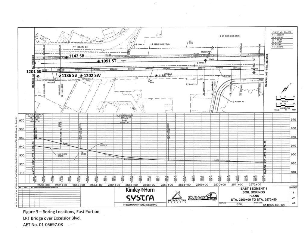
1 FOUNDATION ANALYSIS AND DESIGN REPORT TO: FROM: Mark Bishop, PE, Kimley-Hom and Associates, Inc. Jeffery K. Voyen, PE, American Engineering Testing, Inc. DATE: June 25, 2014 SUBJECT: LRT Bridge over Excelsior Boulevard Southwest Light Rail Transit Project Hopkins, Minnesota AETNo PROJECT INFORMATION This report provides foundation analysis and recommendations for the bridge which will carry the light rail transit (LR T) tracks over Excelsior Boulevard in Hopkins, Minnesota. The new bridge will be a seven span, post-tensioned box girder structure, having a total length of 1,720 feet and width of feet. Current substructure data is presented in Table 1.0. Table Bridge Substructure Data Span Length Bottom of Substructure Station (from prior Foundation substructure) Elevation West Abutment *918.5' Pier ' 914.3' Pier ' 914.2' Pier ' 913.1' Pier ' 911.2' Pier ' 916.5' Pier ' 916.9' East Abutment ' *921.5' * approximate The plan and profile sheets from the preliminary bridge plans are attached to this report. The approaches will be contained within parallel retaining walls, which will have a face-to-face width matching the bridge width. The wall heights from ground surface will be about 11 feet and 18Yz feet at the contacts with the west and east abutments, respectively. 2.0 SUBSURFACE EXPLORATION AND TESTING SUMMARY 2.1 Field Exploration Scope The exploratory test program performed specific to this bridge consisted of eleven standard penetration test (SPT) "foundation" borings. Two of these borings included coring of the bedrock (1141 SB and 1142 SB). Four shallower SPT borings were also conducted in the retained wall
2 Foundation Analysis and Design Report SWLRT Bridge Over Excelsior Blvd June 25, 2014 Report No AMERICAN ENGINEERING TESTING, INC. approach areas, and are also included with this report. The locations of the borings appear on attached Figures 1 to 3. The County coordinates also appear on the logs. 2.2 Laboratory Scope During laboratory classification logging, water content tests were conducted on cohesive soil samples. In addition, two unconfined compression tests with density and one organic content test were performed (Boring 1001 SB). The test results appear on the individual boring logs, opposite the samples upon which they were performed. 2.3 Methods Logs of the SPT borings are attached. The borings were drilled using 3.25 inch diameter hollow stem augers and mud rotary drilling (plug drilling) techniques. Standard penetration test samples were taken with split-barrel samplers per ASTM: D1586, with the exception that the hammers were calibrated to near N6o values per MnDOT requirements. Rock coring was performed in general accordance with ASTM:D2113, using an NQ size wireline system. The soils were visually-manually classified per the Unified Soil Classification System. The soil group category per the AASHTO Soil Classification System is also noted on most of the logs. Please refer to the attachments entitled Exploration/Classification Methods, Boring Log Notes, Unified Soil Classification System, and AASHTO Soil Classification System for additional details. Field and laboratory testing is done in general conformance with the described procedures. Compliance with any other standards referenced within the specified standard is neither inferred nor implied. 2.4 Geology/Soils Review Bedrock The bedrock beneath the bridge ranges in depth from about 85 feet to 98 feet (corresponding to approximate elevation 837 feet to 825Yz feet). The greater depths are found in the more central portion of the bridge. The bedrock is limestone of the Platteville Formation. Much of the upper Platteville Formation present appears to be the Magnolia member, although the Magnolia appears to be absent in the deeper central portion, thereby making the Hidden Falls member the upper portion of the in-place bedrock. Both the Magnolia and the Hidden Falls members appear to be weathered to varying degrees, with some zones being highly weathered. The Mifflin member underlies the Hidden Falls member, below about elevation 823Yz feet, and is expected to be fresh, highly competent bedrock. As much of the penetration into the bedrock was done with tricone advancement (i.e., plug drilling), much of the samples retrieved were "wash samples" from the drilling fluid. This limits our ability to identify whether the material were weathered bedrock or colluvium (rock pieces/residual rock which has fallen into place). In any event, N values could be recorded, and highly resistant materials were reached. Page 2 of9
3 Foundation Analysis and Design Report SWLRT Bridge Over Excelsior Blvd June 25, 2014 Report No AMERICAN ENGINEERING TESTING, INC Natural Overburden Soils The generalized natural soil profile consists of alluvium (water-deposited soils) over glaciallydeposited till soils, although alluvium is usually interbedded in the till and is sometimes substantial in thickness. The alluvium is mostly granular, mainly consisting of sand and sand with silt having varying gravel content. In some areas, clay alluvium is present, including at the top of the natural soil deposit at some on the more centrally located borings. Boring 1001 SB includes organic clay topsoil buried below 61/z feet of fill. The till mostly consists of clayey sand and silty sand, again having varying gravel content. Typically, till exhibits high N-values due to glacial ice overconsolidation. However, a number of the borings indicate substantial thickness zones of "lower than normal" N-values (3 to 7 bpf) in the 865 feet to 895 feet elevation range. In some cases, split-spoon sample recovery did not occur or was limited. Considering the non-uniform profile (substantial thickness of till in close proximity to substantial thickness of alluvium at common depth), it appears some depositional anomalies may exist which may account for the N-value variation. Still, we expect the lower N value tills to have some degree of overconsolidation Upper Fill Fill is present over the natural soils in this existing rail corridor. The fill thickness ranges from about 4 feet to 111/z feet. The fill is primarily granular (sands to silty sands), although does include intermixing with clayey sands and clays. The fill sometimes includes organic fines, ash/cinders, and debris. 2.5 Ground Water Ground-water levels were encountered during drilling. Most of these levels were recorded in faster draining alluvial granular soils which should provide a relatively good indication of the true hydrostatic level for that time and location. Based on those borings, the steady-state groundwater level is in the elevation range of 904 feet to 907 feet. Borings showing lower ground-water elevations were recorded in slower draining soils; and it is expected that the levels would have risen given more time. Water levels are expected to fluctuate both seasonally and annually. The 3-foot elevation range stated appears to be a result of seasonal fluctuations, as the more recent borings drilled this spring show higher elevations than those drilled during the early stage of the project (March of2013). Page 3 of 9

4 Foundation Analysis and Design Report SWLRT Bridge Over Excelsior Blvd June 25, 2014 Report No AMERICAN ENGINEERING TESTING, INC. 3.0 FOUNDATION ANALYSIS 3.1 Foundation Analysis Foundation Type Spread foundation support was not analyzed. Some soil correction would be needed at many locations. The correction would require excavation of all fill, topsoil, and upper clay alluvium, resulting in excavation depths up to 11 Yz feet or more, which is likely complicated by space limitations. Even with this correction, it is anticipated that foundation sizes would be quite large due to the combination of high loads and apparent variation in compressibility properties. In order to provide confidence in uniform support across the bridge, it is recommended that deep foundation support be used. Spread footing support for the retained approaches may be acceptable, however, if space allows for the necessary correction. Considering the varying depth of looser soils, which often extend to considerable depth, it is expected that the use of driven piles will be more economical than drilled shafts. Since the overburden soils are not expected to provide high levels of nominal resistance, it is expected that piles driven to "refusal" in the bedrock will be required to support the bridge. In this area, the use of H-pile is the common pile type for this case, and is the pile type analyzed and recommended in this report. Our analysis focused on the use of HP12x53 and HPl 4xl 17 piles sizes, largely to show a range. Our recommendations will include maximum Factored Pile Bearing Resistance values for other sizes as well Pile Foundation Analysis Methods Pile bearing resistance versus pile length was analyzed using DRIVEN software (FHWA). This program uses the Nordlund method for granular soils and the Tomlinson method for cohesive soils. The granular soil internal friction angle used was based on its relationship to standard penetration test values as presented by Peck, Hanson, and Thorburn (1974), with the N-values being corrected for the influence of the effective overburden pressure. For cohesive soils, we estimated undrained shear strength based on correlations with the SPT data. The "ultimate capacity" determined from this DRIVEN analysis is considered the Nominal Resistance of Single Pile in Axial Compression (Rn) using LRFD terminology. DRIVEN does not specifically address bedrock resistance ( other than allowing input of very high values of cohesion). However, it is expected that if nominal resistance needs are not met prior to reaching the bedrock, high tip resistance will be gained with minimal penetration into the bedrock. Therefore, the DRIVEN analysis performed only evaluates whether resistance is met before reaching the highly resistant bedrock. Page 4 of9
5 Foundation Analysis and Design Report SWLRT Bridge Over Excelsior Blvd June 25, 2014 Report No AMERICAN ENGINEERING TESTING, INC Analysis Results The nominal resistance (ultimate capacity) needed to be demonstrated in the field depends on the Resistance Factor allowed by the "Condition/Resistance Determination Method" used. A Resistance Factor (cp) of 0.65 can be used when dynamic analysis is employed. A Resistance Factor (cp) of 0.60 can be used when the MPF12 driving formula (MnDOT's new formula) is used. Where H-pile is used, either the MPF12 driving formula or dynamic analysis could be used for field evaluation, although dynamic analysis allows for better evaluation of whether or not pile damage is occurring. In the case of HP12x53 pile designed for cprn of 140 tons, a nominal resistance of 431 kips (PDA verification) or 467 kips (MPF12 verification) would then need to be demonstrated. In the case of HP14xll 7 pile designed for cprn of 300 tons, a nominal resistance of 923 kips (PDA verification) or 1000 kips (MPF12 verification) would then need to be demonstrated. Our analysis was not conducted for all of the borings performed. The reason is that the analysis conducted on a few representative locations demonstrates that the nominal resistance will need to be gained by driving the piles into the bedrock where high tip resistance is expected. The analysis was conducted based on the following borings: 1188 SB (Pier 3) 1190 SB (West Abutment) 1218 SB (Pier 5) The DRIVEN results for HP 12x5 3 and HP 14 x 117 piles based on the above listed borings are presented on attached Figures 4 to 6. As shown, nominal resistance needs was not met in the overburden soils, or was met a short distance above the bedrock. Upon reaching bedrock, it is expected that tip resistance will be significantly increased to the point of meeting nominal resistance requirements. Some minor penetration into more highly weathered bedrock zones may occur, but it is expected resistance needs will be quickly gained with this rock penetration. The lengths predicted at each boring location are shown in Table These lengths are based on penetration into the bedrock based on our interpretation of the bedrock quality; and should generally be similar for all H-pile sizes. Page 5 of9
6 Foundation Analysis and Design Report SWLRT Bridge Over Excelsior Blvd June 25, 2014 Report No AMERICAN ENGINEERING TESTING, INC. Substructure Table Estimated Pile Lengths Boring/CP TNo. Proposed Bottom of Footing Elevation, ft Estimated Tip Elevation, ft Estimated Pile Length, ft West Abutment 1141 SB West Abutment 1190 SB Pier SB Pier SB Pier SB E of Pier SB Pier SB Pier SB Pier SB East Abutment 1186 SB East Abutment 1142 SB Retained Wall Approach Settlement Review The proposed bridge approaches will be about 30 feet wide and will raise grade by about 11 feet at the west abutment to 18Yz at the east abutment. Assuming the retained wall approach were to be supported on spread foundations rather than piles, soil correction would be needed to remove the fill and alluvial clays and be replaced with engineered fill. The borings show that excavation depths near the abutments are expected to be on the order of 4 to 6Yz feet, which is only several feet below anticipated frost foundation depths. However, this will increase in areas away from the abutments. Several borings are available at or near each abutment. Based on these borings and assuming Select Granular backfill is placed, we estimate approach settlements will be less Yz inch at the west abutment and less than 1 inch at the east abutment. Also, the majority of this settlement will occur shortly after load application such that track settlement tolerance requirements are expected to be met. Page 6 of 9
7 Foundation Analysis and Design Report SWLRT Bridge Over Excelsior Blvd June 25, 2014 Report No AMERICAN ENGINEERING TESTING, INC. 4.0 FOUNDATION RECOMMENDATIONS 4.1 HP12x53 Piles The bridge foundations can be supported on H-piles, meeting ASTM A572, Grade 50 (fy = 50 ksi). The piles should be equipped with rock points. Various sizes of H-piles can be considered, as listed below. These piles can be designed based on the maximum Factored Pile Bearing Resistance ( cprn) values shown for each size. HP12x53, 140 tons HP12x84, 215 tons HP14x73, 190 tons HP14x89, 225 tons HP14x102, 260 tons HP14xll 7,300 tons The nominal resistance of the piles can be evaluated using either high strain dynamic (PDA) testing or the MnDOT MPF12 driving formula. The dynamic testing should meet the minimum requirements listed in Section of the AASHTO LRFD Bridge Design Specifications, This approach includes Quality Control of non-tested pile by calibrated wave equation analyses. Resistance Factors of 0.65 or 0.60 should be employed for PDA or MPF12 field analysis methods, respectively. It is anticipated that all H-piles sizes would establish required resistance with "refusal" upon the bedrock. Estimated tip elevations are shown in Table Based on the anticipated settlement around the piles due to the retained wall approach system, it is our opinion that downdrag (DD) loads do not need to be considered in the pile design. A reduction factor for group effects does not need to be applied provided the pile arrangement maintains a center-to-center spacing of 3 times the flange length. All foundations should have five or more piles for redundancy purposes. With five or more piles, a reduction factor for a lack of redundancy does not need to be applied. Boulders or rock slabs may potentially be present within the profile. If pile penetration appears to be obstructed at abnormally variable depths (due to apparent boulders/slabs), additional pile and foundation review may be needed. 4.4 Approach Retaining Wall Foundation Support The borings in the abutment areas indicate fill soils and/or alluvial clays are present to depths of 4 feet to 6Yz feet below the current surface. These upper soils are underlain by more competent granular soils which are judged to be capable of supporting the wall foundations and interior fill Page 7 of9
8 Foundation Analysis and Design Report SWLRT Bridge Over Excelsior Blvd June 25, 2014 Report No AMERICAN ENGINEERING TESTING, INC. system, provided exposed looser sands are densified. Borings away from the abutments indicate greater depths of soils needing excavation and the bottoms will expose clayey till soils. To allow spread foundation support of the wall and of the interior fill system, the soils should be subcut to the natural granular soils present beneath the fill and clay alluvium or to the till soils. Where granular soils are exposed, they should be surface compacted with a vibratory roller compactor. The excavation bottoms should be laterally oversized beyond the planned footing edges at a 1: 1 ratio. If space is limited, it would be possible to lower the footing to meet oversize requirements. Preliminary excavation depths anticipated to allow spread foundation support is shown in Table 4.4. Table Excavation Depths Approach Boring No. Boring Ground Elevation, ft Excavation Depth, ft Excavation Elevation, ft West 1141 SB Yz West 1190 SB Yz 916 West 1191 SW West 1200 SW Yz 910Yz East 1091 ST East 1142 SB East 1186 SB Yz 918 East 1202 SW Yz Engineered fill placed to establish foundation grade should meet the requirements of MnDOT Specification B2, Select Granular Borrow. The granular fill should be placed and compacted in accordance with MnDOT Specification Compaction should meet the Specified Density Method, with the modification that the entire thickness of the new fill below the footing be compacted to a minimum of 100% of the Standard Proctor density. If spread foundation support is used (in lieu of pile support), additional testing and analysis should be performed with regards to this element of the bridge design during the final design stage of the project. This should include additional borings to better determine soil correction needs. LRFD foundation analysis considering Bearing Resistance in the strength and service Page 8 of 9
9 Foundation Analysis and Design Report SWLRT Bridge Over Excelsior Blvd June 25, 2014 Report No AMERICAN ENGINEERING TESTING, INC. limit states, sliding resistance, and global stability should be evaluated. For preliminary price evaluation, a 3000 psf allowable bearing pressure (using ASD methods) can be assumed. 4.5 Abutment/Retaining Wall Backfilling The imbalanced abutment walls and retaining walls must be designed to resist the lateral pressures exerted. Where lightweight fill is not used, the backfill material should consist of Select Granular Borrow (MnDOT B2), which is modified to containing less than 10% by weight passing the #200 sieve. Typical "Select Granular Borrow 10% Modified" geometry is shown on attached MnDOT Diagram F-1. However, all excavation backsloping must also meet OSHA requirements. For proper track approach performance, frost tapering of the Select Granular Borrow over frost susceptible soils should be maintained at no steeper than 1 V :20H within the frost zone (assume a frost zone of 4.5 feet). The backfill should be compacted per the Specified Density Method (MnDOT Fl). I hereby certify that this report was prepared by me or under my direct supervision and that I am a duly Licensed Professional Engineer under Minnesota S tute Section ~2~ 2 to Name: t..1/4~ Jeffery K. Voyen Date: ----' '-+---Li3 ~ l1!l,a Report Reviewed By: _-~--, Gregory R. Reuter, PE, PG, Principal Engineer Attachments: Preliminary Bridge Plan-Profile Sheets Figures 1 to 3 - Boring Locations Figures 4 to 6 - DRIVEN Pile Analyses Subsurface Boring Logs Exploration/Classification Methods Boring LogNotes Unified Soil Classification System AASHTO Soil Classification System MnDOT Diagram F-1 Page 9 of 9

10

11

12

13

14

15
16
17
18
19
20
21
22
23
24
25
26

27
28
29
30
31
32
33
34
35
36
37
38

39
40
41
42
43
44
45
46
47

48
49
50
51
52
53
54
55
56
57
58 EXPLORATION/CLASSIFICATION METHODS SAMPLING METHODS Split-Spoon Samples (SS) - Calibrated to N 60 Values Standard penetration (split-spoon) samples were collected in general accordance with ASTM: D1586 with one primary modification. The ASTM test method consists of driving a 2" O.D. split-baltel sampler into the in-situ soil with a 140-pound hammer dropped from a height of 30". The sampler is driven a total of 18" into the soil. After an initial set of 6", the number of hammer blows to drive the sampler the final 12" is known as the standard penetration resistance or N-value. Our method uses a modified hammer weight, which is determined by measuring the system energy using a Pile Driving Analyzer (PDA) and an instrumented rod. In the past, standard penetration N-value tests were performed using a rope and cathead for the lift and drop system. The energy transferred to the split-spoon sampler was typically limited to about 60% of its potential energy due to the friction inherent in this system. This converted energy then provides what is known as an N 60 blow count. Most of today's drill rigs incorporate an automatic hammer lift and drop system, which has higher energy efficiency and subsequently results in lower N-values than the traditional N 60 values. By using the PDA energy measurement equipment, we are able to detennine actual energy generated by the drop hammer. With the various hammer systems available, we have found highly variable energies ranging from 55% to over 100%. Therefore, the intent of AET's hammer calibrations is to vary the hammer weight such that hammer energies lie within about 60% to 65% of the theoretical energy of a 140-pound weight falling 30". The current ASTM procedure acknowledges the wide variation in N-values, stating that N-values of 100% or more have been observed. Although we have not yet determined the statistical measurement uncertainty of our calibrated method to date, we can state that the accuracy deviations of the N-values using this method are significantly better than the standard ASTM Method. Sampling Limitations Unless actually observed in a sample, contacts between soil layers are estimated based on the spacing of samples and the action of drilling tools. Cobbles, boulders, and other large objects generally cannot be recovered from test borings, and they may be present in the ground even if they are not noted on the boring logs. CLASSIFICATION METHODS Soil classifications shown on the boring logs are based on the Unified Soil Classification (USC) system. The USC system is described in ASTM: D2487 and D2488. Where laboratory classification tests (sieve analysis or Atterberg Limits) have been performed, accurate classifications per ASTM: D2487 are possible. Otherwise, soil classifications shown on the boring logs are visual-manual judgments. Charts are attached which provide information on the USC system, the descriptive terminology, and the symbols used on the boring logs. Visual-manual judgment of the AASHTO Soil Group is also noted as a part of the soil description. A chart presenting details of the AASHTO Soil Classification System is also attached. The boring logs include descriptions of apparent geology. The geologic depositional origin of each soil layer is interpreted primarily by observation of the soil samples, which can be limited. Observations of the su1tounding topography, vegetation, and development can sometimes aid this judgment. WATER LEVEL MEASUREMENTS The ground-water level measurements/comments are shown on the boring logs in the remarks section. The true location of the water table at the boring locations may be different than the water levels measured in the boreholes. This is possible because there are several factors that can affect the water level measurements in the borehole. Some of these factors include: permeability of each soil layer in profile, presence of perched water, amount of time between water level readings, presence of drilling fluid, weather conditions, and use of borehole casing. SAMPLE STORAGE Unless notified to do otherwise, we routinely retain representative samples of the soils recovered from the borings for a period of 30 days. 01REP051C (12/08) AMERICAN ENGINEERING TESTING, INC.
59 BORING LOG NOTES DRILLING AND SAMPLING SYMBOLS Symbol Definition AR: Sample of material obtained from cuttings blown out the top of the borehole during air rotary procedure. B,H,N: Size of flush-joint casing CAS: Pipe casing, number indicates nominal diameter in inches COT: Clean-out tube DC: Drive casing; number indicates diameter in inches DM: Drilling mud or bentonite slurry DR: Driller (initials) DS: Disturbed sample from auger flights DP: Direct push drilling; a inch OD outer casing with an inner 1 Yz inch ID plastic tube is driven continuously into the ground. FA: Flight auger; number indicates outside diameter in inches HA: Hand auger; number indicates outside diameter HSA: Hollow stern auger; number indicates inside diameter in inches LG: Field logger (initials) MC: Column used to describe moisture condition of samples and for the ground water level symbols N (BPF): Standard penetration resistance (N-value) in blows per foot ( see notes) NQ: NQ wireline core barrel PD: Plug Drilling (same as RDF) PQ: PQ wireline core barrel RDA: Rotary drilling with compressed air and roller or drag bit. RDF: Rotary drilling with drilling fluid and roller or drag bit REC: In split-spoon (see notes), direct push and thin-walled tube sampling, the recovered length (in inches) of sample. In rock coring, the length of core recovered (expressed as percent of the total core run). Zero indicates no sample recovered. SS: Standard split-spoon sampler (steel; 1.5" is inside diameter; 2" outside diameter); unless indicated otherwise SU Spin-up sample from hollow stem auger TW: Thin-walled tube; number indicates inside diameter in inches WASH: Sample of material obtained by screening returning rotary drilling fluid or by which has collected inside the borehole after "falling" through drilling fluid WH: Sampler advanced by static weight of drill rod and hammer WR: Sampler advanced by static weight of drill rod 94mm: 94 millimeter wireline core barrel T: Water level directly measured in boring v: Estimated water level based solely on sample appearance TEST SYMBOLS Symbol Definition COH: Cohesion, psf (0.5 x qu) CONS: One-dimensional consolidation test y: Wet density, pcf DST: Direct shear test E: Pressuremeter Modulus, tsf HYD: Hydrometer analysis LL: Liquid Limit, % LP: Pressuremeter Limit Pressure, tsf MC: Moisture Content, % OC: Organic Content, % PERM: Coefficient of permeability (K) test; F - Field; L - Laboratory PL: Plastic Limit,% qp: Pocket Penetrometer strength, tsf (approximate) qc: Static cone bearing pressure, tsf qu: Unconfined compressive strength, psf R: Electrical Resistivity, ohm-ems RQD: Rock Quality Designation of Rock Core, in percent (aggregate length of core pieces 4" or more in length as a percent of total core run) SA: Sieve analysis TRX: Triaxial compression test VSR: Vane shear strength, remolded (field), psf VSU: Vane shear strength, undisturbed (field), psf %-200: Percent of material finer than #200 sieve STANDARD PENETRATION TEST NOTES (Calibrated Hammer Weight) The standard penetration test consists of driving a split-spoon sampler with a drop hammer ( calibrated weight varies to provide N 60 values) and counting the number of blows applied in each of three 6" increments of penetration. If the sampler is driven less than 18" (usually in highly resistant material), permitted in ASTM: D 1586, the blows for each complete 6" increment and for each partial increment is on the boring log. For partial increments, the number of blows is shown to the nearest 0.1' below the slash. The length of sample recovered, as shown on the "REC" column, may be greater than the distance indicated in the N column. The disparity is because the N-value is recorded below the initial 6" set (unless partial penetration defined in ASTM: D1586 is encountered) whereas the length of sample recovered is for the entire sampler drive (which may even extend more than 18"). 01REP052C (7/11) AMERICAN ENGINEERING TESTING, INC.

60
61
62
Chapter 12 Subsurface Exploration
 Page 12 1 Chapter 12 Subsurface Exploration 1. The process of identifying the layers of deposits that underlie a proposed structure and their physical characteristics is generally referred to as (a) subsurface
Boreholes. Implementation. Boring. Boreholes may be excavated by one of these methods: 1. Auger Boring 2. Wash Boring 3.
 Implementation Boreholes 1. Auger Boring 2. Wash Boring 3. Rotary Drilling Boring Boreholes may be excavated by one of these methods: 4. Percussion Drilling The right choice of method depends on: Ground
B-1 BORE LOCATION PLAN. EXHIBIT Drawn By: 115G BROOKS VETERINARY CLINIC CITY BASE LANDING AND GOLIAD ROAD SAN ANTONIO, TEXAS.
 N B-1 SYMBOLS: Exploratory Boring Location Project Mngr: BORE LOCATION PLAN Project No. GK EXHIBIT Drawn By: 115G1063.02 GK Scale: Checked By: 1045 Central Parkway North, Suite 103 San Antonio, Texas 78232
Civil Engineering, Surveying and Environmental Consulting WASP0059.ltr.JLS.Mich Ave Bridge Geotech.docx
 2365 Haggerty Road South * Canton, Michigan 48188 P: 734-397-3100 * F: 734-397-3131 * www.manniksmithgroup.com August 29, 2012 Mr. Richard Kent Washtenaw County Parks and Recreation Commission 2330 Platt
Geotechnical Engineering Report
 Geotechnical Engineering Report Turner Turnpike Widening Bridge B Bridge Crossing: South 257 th West Avenue Creek County, Oklahoma June 1, 2016 Terracon Project No. 04155197 Prepared for: Garver, LLC Tulsa,
SITE INVESTIGATION 1
 SITE INVESTIGATION 1 Definition The process of determining the layers of natural soil deposits that will underlie a proposed structure and their physical properties is generally referred to as site investigation.
Geotechnical Engineering Report
 Geotechnical Engineering Report Turner Turnpike Widening Bridge D Bridge Crossing: South 209 th West Avenue Creek County, Oklahoma June 1, 2016 Terracon Project No. 04155197 Prepared for: Garver, LLC Tulsa,
Geotechnical Engineering Report
 Geotechnical Engineering Report Turner Turnpike Widening Polecat Creek Bridge (Bridge A) June 1, 2016 Terracon Project No. 04155197 Prepared for: Garver, LLC Prepared by: Terracon Consultants, Inc. TABLE
December 13, Washington County Public Works Department Myeron Road North Stillwater, MN Attn: Mr. Andrew Giesen
 CONSULTANTS ENVIRONMENTAL GEOTECHNICAL MATERIALS FORENSICS December 13, 2016 Washington County Public Works Department 11660 Myeron Road North Stillwater, MN 55082 Attn: Mr. Andrew Giesen RE: Geotechnical
KDOT Geotechnical Manual Edition. Table of Contents
 KDOT Geotechnical Manual 2007 Edition The KDOT Geotechnical Manual is available two volumes. Both volumes are very large electronic (pdf) files which may take several minutes to download. The table of
The process of determining the layers of natural soil deposits that will underlie a proposed structure and their physical properties is generally
 The process of determining the layers of natural soil deposits that will underlie a proposed structure and their physical properties is generally referred to as sub surface investigation 2 1 For proper
 Project: ITHACA-TOMPKINS REGIONAL AIRPORT EXPANSION Project Location: ITHACA, NY Project Number: 218-34 Key to Soil Symbols and Terms TERMS DESCRIBING CONSISTENCY OR CONDITION COARSE-GRAINED SOILS (major
ENCE 3610 Soil Mechanics. Site Exploration and Characterisation Field Exploration Methods
 ENCE 3610 Soil Mechanics Site Exploration and Characterisation Field Exploration Methods Geotechnical Involvement in Project Phases Planning Design Alternatives Preparation of Detailed Plans Final Design
REPORT OF SUBSURFACE EXPLORATION
 REPORT OF SUBSURFACE EXPLORATION GRAND RIVER DAM AUTHORITY HULBERT 69 KV SWITCHING STATION S. 440 Road Hulbert, Cherokee County, Oklahoma ENERCON PROJECT NO. GRDA006 MARCH 7, 2012 PREPARED FOR: C/O ENERCON
Depth (ft) USCS Soil Description TOPSOIL & FOREST DUFF
 USCS Soil Description TOPSOIL & FOREST DUFF") Test Pit No. TP-6 Location: Latitude 47.543003, Longitude -121.980441 Approximate Ground Surface Elevation: 1,132 feet Depth (ft) USCS Soil Description 0 1.5 1.5 5.0 SM 5.0 8.0 SM Loose to medium dense,
Test Pit No. TP-6 Location: Latitude 47.543003, Longitude -121.980441 Approximate Ground Surface Elevation: 1,132 feet Depth (ft) USCS Soil Description 0 1.5 1.5 5.0 SM 5.0 8.0 SM Loose to medium dense,
ATTACHMENT A PRELIMINARY GEOTECHNICAL SUMMARY
 ATTACHMENT A PRELIMINARY GEOTECHNICAL SUMMARY Kevin M. Martin, P.E. KMM Geotechnical Consultants, LLC 7 Marshall Road Hampstead, NH 0384 603-489-6 (p)/ 603-489-8 (f)/78-78-4084(m) kevinmartinpe@aol.com
Safe bearing capacity evaluation of the bridge site along Syafrubesi-Rasuwagadhi road, Central Nepal
 Bulletin of the Department of Geology Bulletin of the Department of Geology, Tribhuvan University, Kathmandu, Nepal, Vol. 12, 2009, pp. 95 100 Safe bearing capacity evaluation of the bridge site along
June 9, R. D. Cook, P.Eng. Soils Engineer Special Services Western Region PUBLIC WORKS CANADA WESTERN REGION REPORT ON
 PUBLIC WORKS CANADA WESTERN REGION REPORT ON GEOTECHNICAL INVESTIGATION PROPOSED MARTIN RIVER BRIDGE MILE 306.7 MACKENZIE HIGHWAY Submitted by : R. D. Cook, P.Eng. Soils Engineer Special Services Western
Preliminary Geotechnical Investigation Cadiz / Trigg County I-24 Business Park. Cadiz, Kentucky
 Environmental & Geoscience, LLC 834 Madisonville Road Hopkinsville, KY 440 70.44.000 FAX 70.44.8300 www.wedrill.com A member of Trinity Energy & Infrastructure Group, LLC Preliminary Geotechnical Investigation
APPENDIX E SOILS TEST REPORTS
 Otsego County, NY Site Work Specifications APPENDIX E SOILS TEST REPORTS Blue Wing Services, Inc. July 1, 2010 Blue Wing Services May 20, 2010 Page 2 the site, was not made available to Empire at this
Limited Geotechnical Engineering Evaluation Classroom Additions Albany County Campus Laramie, Wyoming
 Limited Geotechnical Engineering Evaluation Classroom Additions Albany County Campus 2300 Missile Drive, Cheyenne, Wyoming 82001 Phone 307-635-0222 www.stratageotech.com Limited Geotechnical Engineering
Geotechnical Investigation Juneau Seawalk - Taku Fisheries to Miner s Wharf Juneau, Alaska DM&A Job No
 Duane Miller & Associates 5821 Arctic Boulevard, Suite A Anchorage, AK 99518-1654 (907) 644-3200 Fax 644-0507 Arctic & Geotechnical Engineering May 4, 2006 Tetra Tech/KCM, Inc. 1971 First Avenue Seattle,
Manual on Subsurface Investigations National Highway Institute Publication No. FHWA NHI Federal Highway Administration Washington, DC
 Manual on Subsurface Investigations National Highway Institute Publication No. FHWA NHI-01-031 Federal Highway Administration Washington, DC Geotechnical Site Characterization July 2001 by Paul W. Mayne,
 SOIL CLASSIFICATION CHART COARSE-GRAINED SOILS MORE THAN 50% RETAINED ON NO.200 SIEVE FINE-GRAINED SOILS 50% OR MORE PASSES THE NO.200 SIEVE PRIMARY DIVISIONS GRAVELS MORE THAN 50% OF COARSE FRACTION RETAINED
INTRODUCTION TO STATIC ANALYSIS PDPI 2013
 INTRODUCTION TO STATIC ANALYSIS PDPI 2013 What is Pile Capacity? When we load a pile until IT Fails what is IT Strength Considerations Two Failure Modes 1. Pile structural failure controlled by allowable
PRELIMINARY GEOTECHNICAL ENGINEERING REPORT. Proposed Re-Development 44 Old Worcester Road Charlton, Massachusetts. Prepared For:
 PRELIMINARY GEOTECHNICAL ENGINEERING REPORT Proposed Re-Development 44 Old Worcester Road Charlton, Massachusetts Prepared For: Meridian Associates, Inc. 500 Cummings Center, Suite 5950 Beverly, Massachusetts
GEOTECHNICAL REPORT. Matanuska-Susitna Borough. Parks Highway Connections Museum Drive. Matanuska-Susitna Borough, Alaska.
 Matanuska-Susitna Borough GEOTECHNICAL REPORT Parks Highway Connections Museum Drive Matanuska-Susitna Borough, Alaska March 2, 20 Prepared By: John Thornley, PE Geotechnical Engineer 333 Arctic Blvd.,
Geotechnical Engineering Study, Conifer Senior High School Football Field Improvements, Conifer, Colorado
 2390 South Lipan Street Denver, CO 80223 phone: (303) 742-9700 fax: (303) 742-9666 email: kadenver@kumarusa.com www.kumarusa.com Office Locations: Denver (HQ), Colorado Springs, Fort Collins, and Frisco,
Pierce County Department of Planning and Land Services Development Engineering Section
 Page 1 of 7 Pierce County Department of Planning and Land Services Development Engineering Section PROJECT NAME: DATE: APPLICATION NO.: PCDE NO.: LANDSLIDE HAZARD AREA (LHA) GEOLOGICAL ASSESSMENT REPORT
 Photo 1 - Southerly view across 2700 parking lot toward existing building. Multi-residential building borders western side of property in upper right of view. Photo 2 - Southerly view across 2750 parking
M E M O R A N D U M. Mr. Jonathan K. Thrasher, P.E., Mr. Ian Kinnear, P.E. (FL) PSI
 PSI") M E M O R A N D U M TO: FROM: Mr. Mark Schilling Gulf Interstate Engineering Mr. Jonathan K. Thrasher, P.E., Mr. Ian Kinnear, P.E. (FL) PSI DATE: November 11, 2014 RE: Summary of Findings Geotechnical
M E M O R A N D U M TO: FROM: Mr. Mark Schilling Gulf Interstate Engineering Mr. Jonathan K. Thrasher, P.E., Mr. Ian Kinnear, P.E. (FL) PSI DATE: November 11, 2014 RE: Summary of Findings Geotechnical
GEOTECHNICAL INVESTIGATION REPORT
 GEOTECHNICAL INVESTIGATION REPORT SOIL INVESTIGATION REPORT FOR STATIC TEST FACILITY FOR PROPELLANTS AT BDL, IBRAHIMPATNAM. Graphics Designers, M/s Architecture & Engineering 859, Banjara Avenue, Consultancy
ENGINEERING ASSOCIATES
 July 16, 211 Vista Design, Inc. 11634 Worcester Highway Showell, Maryland 21862 Attention: Reference: Dear Mr. Polk: Mr. Richard F. Polk, P.E. Geotechnical Engineering Report Charles County RFP No. 11-9
IN SITU SPECIFIC GRAVITY VS GRAIN SIZE: A BETTER METHOD TO ESTIMATE NEW WORK DREDGING PRODUCTION
 IN SITU SPECIFIC GRAVITY VS GRAIN SIZE: A BETTER METHOD TO ESTIMATE NEW WORK DREDGING PRODUCTION Nancy Case O Bourke, PE 1, Gregory L. Hartman, PE 2 and Paul Fuglevand, PE 3 ABSTRACT In-situ specific gravity
The attitude he maintains in his relation to the engineer is very well stated in his own words:
 Su bsurface Soil Exploration, 53: 139 Foundation Engineering Geotechnical companies that have a history of experience in a given region usually have extensive boring logs and maps telling where the borings
APPENDIX C. Borehole Data
 APPENDIX C Borehole Data MAJOR DIVISIONS SOIL CLASSIFICATION CHART SYMBOLS GRAPH LETTER TYPICAL DESCRIPTIONS ADDITIONAL MATERIAL
Geotechnical Engineering Report
 Geotechnical Engineering Report Single-Span Bridge North Western Road & Hall of Fame Avenue August 25, 2015 Terracon Project No. 03155156 Prepared for: Olsson Associates Prepared by: Terracon Consultants,
SCOPE OF INVESTIGATION Simple visual examination of soil at the surface or from shallow test pits. Detailed study of soil and groundwater to a
 Lecture-5 Soil Exploration Dr. Attaullah Shah 1 Today s Lecture Purpose of Soil Exploration Different methods 1. Test trenches and Pits 2. Auger and Wash Boring 3. Rotary Drilling 4. Geophysical Methods
 R-1 Conveyor Relocation Project Legend 0 500 1000 1500 ft. This map is a user generated static output from an Internet mapping site and is for general reference only. Data layers that appear on this map
Chapter 7 GEOMECHANICS
 Chapter 7 Final SCDOT GEOTECHNICAL DESIGN MANUAL August 2008 Table of Contents Section Page 7.1 Introduction...7-1 7.2 Geotechnical Design Approach...7-1 7.3 Geotechnical Engineering Quality Assurance...7-2
Geotechnical Data Report
 Geotechnical Data Report ReWa Solar Farm at Durbin Creek Fountain Inn, South Carolina September 1, 2017 Terracon Project No. 86165043 Prepared for: Renewable Water Resources Greenville, South Carolina
Geotechnical Data Report
 Geotechnical Data Report Downtown Greenville Future Conveyance Study December 1, 2015 Terracon Project No. 86155032 Prepared for: Prepared by: Terracon Consultants, Inc. December 1, 2015 561 Mauldin Road
B-1 SURFACE ELEVATION
 5A 5B LOGGED BY El. S. Bhangoo DRILLING CONTRACTOR Pitcher Drilling DRILLING METHOD Rotary Wash BEGIN DATE 12-14-12 SAMPLER TYPE(S) AND SIZE(S) (ID) SPT, MC BOREHOLE BACKFILL AND COMPLETION COMPLETION
FINAL GEOTECHNICAL INVESTIGATION BURNS BRIDGE REPLACEMENT COLORADO RIVER ROAD BURNS, COLORADO. December 12, 2012
 FINAL GEOTECHNICAL INVESTIGATION BURNS BRIDGE REPLACEMENT COLORADO RIVER ROAD BURNS, COLORADO December 12, 2012 Prepared For: AMEC Environment & Infrastructure 2000 South Colorado Boulevard, Suite 21000
Gotechnical Investigations and Sampling
 Gotechnical Investigations and Sampling Amit Prashant Indian Institute of Technology Gandhinagar Short Course on Geotechnical Investigations for Structural Engineering 12 14 October, 2017 1 Purpose of
APPENDIX F CORRELATION EQUATIONS. F 1 In-Situ Tests
 APPENDIX F 1 APPENDIX F CORRELATION EQUATIONS F 1 In-Situ Tests 1. SPT (1) Sand (Hatanaka and Uchida, 1996), = effective vertical stress = effective friction angle = atmosphere pressure (Shmertmann, 1975)
3.0 SUMMARY OF FINDINGS
 AECOM 500 W Jefferson St. Suite 1600 Louisville, KY 40202 www.aecom.com 502-569-2301 tel 502-569-2304 fax October 17, 2018 Big Rivers Electric Corporation Sebree Generating Station 9000 Highway 2096 Robards,
APPENDIX C HYDROGEOLOGIC INVESTIGATION
 Figure B-5.7 Figure B-5.8 Preliminary Geotechnical and Environmental Report Appendix C Hydrogeologic Investigation APPENDIX C HYDROGEOLOGIC INVESTIGATION December 21, 2011 WESTSIDE SUBWAY EXTENSION PROJECT
GZA GeoEnvironmental, Inc.
 GZA BORING NO.: GZ-1 SHEET: 1 of 1 PROJECT NO: 9.223. Drilling Co.: Geologic Type of Rig: Skid Boring Location: See Plan H. Datum: See Plan Rig Model: Mudline : Foreman: Ray Eastwood CME -.8 Final Boring
DATA REPORT GEOTECHNICAL INVESTIGATION GALVESTON CRUISE TERMINAL 2 GALVESTON, TEXAS
 DATA REPORT GEOTECHNICAL INVESTIGATION GALVESTON CRUISE TERMINAL 2 GALVESTON, TEXAS SUBMITTED TO PORT OF GALVESTON 123 ROSENBERG AVENUE, 8TH FLOOR GALVESTON, TEXAS 77553 BY HVJ ASSOCIATES, INC. HOUSTON,
General. DATE December 10, 2013 PROJECT No TO Mary Jarvis Urbandale/Riverside South Development Corporation
 DATE December 10, 201 PROJECT No. 10-1121-0260- TO Mary Jarvis Urbandale/Riverside South Development Corporation CC Justin Robitaille, Urbandale Jonathan Párraga, J.L. Richards & Associates Limited FROM
December 20, 2017 (Revised from December 15, 2017) Project No
 Project No") December 20, 2017 (Revised from December 15, 2017) Project No. 92270.02 Ms. Laura Krusinski, P.E. Senior Geotechnical Engineer Maine Department of Transportation State House Station 16 Augusta, Maine 04333-016
December 20, 2017 (Revised from December 15, 2017) Project No. 92270.02 Ms. Laura Krusinski, P.E. Senior Geotechnical Engineer Maine Department of Transportation State House Station 16 Augusta, Maine 04333-016
PRELIMINARY GEOTECHNICAL REPORT. State College Redevelopment State College Borough, Centre County, Pennsylvania. CMT Laboratories File No.
 PRELIMINARY GEOTECHNICAL REPORT State College Redevelopment State College Borough, Centre County, Pennsylvania CMT Laboratories File No. 1638700 Prepared for: National Development Council One Battery Park
Soil Mechanics Brief Review. Presented by: Gary L. Seider, P.E.
 Soil Mechanics Brief Review Presented by: Gary L. Seider, P.E. 1 BASIC ROCK TYPES Igneous Rock (e.g. granite, basalt) Rock formed in place by cooling from magma Generally very stiff/strong and often abrasive
10. GEOTECHNICAL EXPLORATION PROGRAM
 Geotechnical site investigations should be conducted in multiple phases to obtain data for use during the planning and design of the tunnel system. Geotechnical investigations typically are performed in
Drilled Shaft Foundations in Limestone. Dan Brown, P.E., Ph.D. Dan Brown and Associates
 Drilled Shaft Foundations in Limestone Dan Brown, P.E., Ph.D. Dan Brown and Associates Foundation Engineering How we teach our students Fundamental understanding of soil and rock behavior (good!) Focus
Ardaman & Associates, Inc. Geotechnical, Environmental and Materials Consultants
 SUBSURFACE SOIL EXPLORATION 42-INCH FORCE MAIN REPLACEMENT CHIQUITA BOULEVARD S AND SW 34 TH STREET CAPE CORAL, LEE COUNTY, FLORIDA Ardaman & Associates, Inc. Geotechnical, Environmental and Materials
Conventional Field Testing & Issues (SPT, CPT, DCPT, Geophysical methods)
") Conventional Field Testing & Issues (SPT, CPT, DCPT, Geophysical methods) Ajanta Sachan Assistant Professor Civil Engineering IIT Gandhinagar Conventional Field Testing 1 Field Test: In-situ shear strength
Conventional Field Testing & Issues (SPT, CPT, DCPT, Geophysical methods) Ajanta Sachan Assistant Professor Civil Engineering IIT Gandhinagar Conventional Field Testing 1 Field Test: In-situ shear strength
IN SITU TESTING TECHNOLOGY FOR FOUNDATION & EARTHQUAKE ENGINEERING. Wesley Spang, Ph.D., P.E. AGRA Earth & Environmental, Inc.
 IN SITU TESTING TECHNOLOGY FOR FOUNDATION & EARTHQUAKE ENGINEERING Wesley Spang, Ph.D., P.E. AGRA Earth & Environmental, Inc. Portland, Oregon In situ testing of soil, which essentially consists of evaluating
In-class Exercise. Problem: Select load factors for the Strength I and Service I Limit States for the. Loading Diagram for Student Exercise
 In-class Exercise Problem: Select load factors for the Strength I and Service I Limit States for the problem illustrated below. Loading Diagram for Student Exercise For this exercise, complete the following
GEOTECHNICAL POLICIES AND PROCEDURES MANUAL CHAPTER 5 GEOTECHNICAL INVESTIGATION PLANNING GUIDELINES
 GEOTECHNICAL POLICIES AND PROCEDURES MANUAL CHAPTER 5 GEOTECHNICAL INVESTIGATION PLANNING GUIDELINES GEOTECHNICAL INVESTIGATION PLANNING GUIDELINES 5-i TABLE OF CONTENTS 1. PURPOSE... 1 2. INTRODUCTION...
LRFD GEOTECHNICAL IMPLEMENTATION
 LRFD GEOTECHNICAL IMPLEMENTATION Ching-Nien Tsai, P.E. LADOTD Pavement and Geotechnical Services In Conjunction with LTRC WHY LRFD FHWA deadline - October 2007 LRFD is a better method Risk is quantified
Instructional Objectives
 GE 343 SUBSURFACE EXPLORATION CH 8 Rock Drilling, Testing, and Sampling Text Ch. 7. Dr. Norbert H. Maerz Missouri University of Science and Technology (573) 341-6714 norbert@mst.edu Instructional Objectives
AN EMPLOYEE OWNED COMPANY
 CTL Engineering, Inc. 2860 Fisher Road, P.O. Box 4448, Columbus, Ohio 43204338 Phone: 614/2768123 Fax: 614/2766377 Email: ctl@ctleng.com AN EMPLOYEE OWNED COMPANY Consulting Engineers Testing Inspection
OVERVIEW REVIEW OF FOUNDATIONS & SOILS ENG.
 Soil Borings. 14.485 CAPSTONE DESIGN OVERVIEW REVIEW OF 14.431 FOUNDATIONS & SOILS ENG. Geotechnical Report (not covered). Bearing Pressure Calculations. Settlement Calculations. Lateral Earth Pressure
APPENDIX A. Borehole Logs Explanation of Terms and Symbols
 APPENDIX A Borehole Logs Explanation of Terms and Symbols Page 153 of 168 EXPLANATION OF TERMS AND SYMBOLS The terms and symbols used on the borehole logs to summarize the results of field investigation
GEOTECHNICAL ENGINEERING SERVICES REPORT
 GEOTECHNICAL ENGINEERING SERVICES REPORT BRIDGE OVER BIG CREEK APPROXIMATELY.8 MILES EAST OF THE INTERSECTION OF COUNTY ROAD EW1546 AND COUNTY ROAD 193 LEFLORE COUNTY, OKLAHOMA PROJECT No. J2-8616(5),
Ardaman & Associates, Inc. Geotechnical, Environmental and Materials Consultants
 SUBSURFACE SOIL EXPLORATION ANALYSIS AND RECOMMENDATIONS LELY AREA STORMWATER IMPROVEMENT PROJECT (LASIP) COUNTY BARN ROAD AND WING SOUTH CHANNELS NAPLES, COLLIER CO., FLORIDA Ardaman & Associates, Inc.
ADDENDUM 1 FISHER SLOUGH RESTORATION PROJECT SKAGIT COUNTY, WASHINGTON
 F I N A L A D D E N D U M 1 R E P O R T ADDENDUM 1 FISHER SLOUGH RESTORATION PROJECT SKAGIT COUNTY, WASHINGTON REPORT OF GEOTECHNICAL INVESTIGATION URS JOB NO. 3376186 Prepared for Tetra Tech Inc. 142
H.1 SUMMARY OF SUBSURFACE STRATIGRAPHY AND MATERIAL PROPERTIES (DATA PACKAGE)
") DRAFT ONONDAGA LAKE CAPPING AND DREDGE AREA AND DEPTH INITIAL DESIGN SUBMITTAL H.1 SUMMARY OF SUBSURFACE STRATIGRAPHY AND MATERIAL PROPERTIES (DATA PACKAGE) Parsons P:\Honeywell -SYR\444576 2008 Capping\09
DRAFT ONONDAGA LAKE CAPPING AND DREDGE AREA AND DEPTH INITIAL DESIGN SUBMITTAL H.1 SUMMARY OF SUBSURFACE STRATIGRAPHY AND MATERIAL PROPERTIES (DATA PACKAGE) Parsons P:\Honeywell -SYR\444576 2008 Capping\09
Appendix E. Phase 2A Geotechnical Data
 Appendix E Phase 2A Geotechnical Data Appendix E1 Geotechnical Testing of Sediment ApPENDIX El. GEOTECHNICAL TESTING OF SEDIMENT (Modified from Exponent, 20Q1c) E.I Introduction This appendix presents
Geotechnical Recommendations for Proposed Additions to the Three Mile Creek Severe Weather Attenuation Tank Project
 TECHNICAL MEMORANDUM Geotechnical Recommendations for Proposed Additions to the Three Mile Creek Severe Weather Attenuation Tank Project PREPARED FOR: PREPARED BY: DATE: June 28, 218 PROJECT NUMBER: 697482
Report of Preliminary Geotechnical Exploration. CSO-012 Sewer Separation Cincinnati, Hamilton County, Ohio. February, 2011
 11242843_GeoTech_Preliminary - Feburary 2011_1/40 Report of Preliminary Geotechnical Exploration CSO-012 Sewer Separation Cincinnati, Hamilton County, Ohio February, 2011 11242843_GeoTech_Preliminary -
Rotary Drilling Rotary Drilling Bits
 GE 343 SUBSURFACE EXPLORATION CH 8 Rock Drilling, Testing, and Sampling Text Ch. 7. Dr. Norbert H. Maerz Missouri University of Science and Technology (573) 341-6714 norbert@mst.edu Instructional Objectives
R.M.HARW & ASSOCIATES LTD. GEOTECHNICAL INVESTIGATION PROPOSED BRIDGE SITE. HELAVA CREEKl MILE MACKENZIE HIGHWAY E-2510 OCTOBER 16, 1973
 El R.M.HARW & ASSOCIATES LTD. GEOTECHNICAL INVESTIGATION PROPOSED BRIDGE SITE HELAVA CREEKl MILE 616.4 MACKENZIE HIGHWAY E-2510 OCTOBER 16, 1973 R,M,HARDV & ASSOCIATES LTD. CONSULTING ENGINEERING & TESTING
 www.novotechsoftware.com The standard penetration test (SPT) is an in-situ dynamic penetration test designed to provide information on the geotechnical engineering properties of soil. The test procedure
Minnesota Department of Transportation Geotechnical Section Cone Penetration Test Index Sheet 1.0 (CPT 1.0)
") This Cone Penetration Test (CPT) Sounding follows ASTM D 5778 and was made by ordinary and conventional methods and with care deemed adequate for the Department's design purposes. Since this sounding was
This Cone Penetration Test (CPT) Sounding follows ASTM D 5778 and was made by ordinary and conventional methods and with care deemed adequate for the Department's design purposes. Since this sounding was
patersongroup Design for Earthquakes Consulting Engineers May 19, 2016 File: PG3733-LET.01
 patersongroup May 19, 2016 File: PG3733-LET.01 Hydro Ottawa Limited c/o Cresa Toronto 170 University Avenue, Suite 1 Toronto, Ontario M5H 3B3 Attention: Ms. Barbara Wright Consulting Engineers 154 Colonnade
ABSTRACT. Use and Application of Piezocone Penetration Testing in Presumpscot Formation
 ABSTRACT Use and Application of Piezocone Penetration Testing in Presumpscot Formation Presumpscot Formation is commonly referred to as glacial marine clay found along the coastline of eastern New England.
FIFTH STREET GRADE SEPARATION CARSON CITY, NEVADA
 GEOTECHNICAL REPORT FIFTH STREET GRADE SEPARATION CARSON CITY, NEVADA JULY 2005 MATERIALS DIVISION STATE OF NEVADA DEPARTMENT OF TRANSPORTATION MATERIALS DIVISION GEOTECHNICAL SECTION GEOTECHNICAL REPORT
GEOTECHNICAL REPORT CBSA Facility Redevelopment Thousand Islands International Crossing Lansdowne, Ontario
 GEOTECHNICAL REPORT CBSA Facility Redevelopment Thousand Islands International Crossing Lansdowne, Ontario Prepared For: The Federal Bridge Corporation Limited SPL Project No.: 10001084 Report Date: January
SUBSURFACE EXPLORATION AND SUBGRADE EVALUATION. Proposed North Main Street Reconstruction (Contract 14-02) From New York Avenue and Murdoch Avenue
 From New York Avenue and Murdoch Avenue") SUBSURFACE EXPLORATION AND SUBGRADE EVALUATION Proposed North Main Street Reconstruction (Contract 14-02) From New York Avenue and Murdoch Avenue Prepared for City of Oshkosh Department of Public Works
SUBSURFACE EXPLORATION AND SUBGRADE EVALUATION Proposed North Main Street Reconstruction (Contract 14-02) From New York Avenue and Murdoch Avenue Prepared for City of Oshkosh Department of Public Works
St. Croix River Crossing Preliminary Engineering Foundation Design Options Report
 Prepared for: Minnesota Department of Transportation and Wisconsin Department of Transportation Prepared by: Parsons Brinckerhoff June 2010 Table of Contents 1 Introduction... 1-1 1.1 Project Description...
Northern Colorado Geotech
 PRELIMINARY GEOTECHNICAL ENGINEERING REPORT PROPOSED CECIL FARMS DEVELOPMENT WELD COUNTY ROAD 7, BETWEEN ROADS 7 AND 7 SEVERANCE, COLORADO NORTHERN COLORADO GEOTECH PROJECT NO. 0-6 APRIL 0, 06 Prepared
Existing Bridge Proposed Bridge 66003
 922 335 9 T2 X 924 919 9 T4 923 T3 919 922 9 T1 925 919 Existing Bridge 6842 919 9 Proposed Bridge 66003 Minnesota Department of Transportation Geotechnical Section Boring Log Descriptive Terminology (English
Ardaman & Associates, Inc. Geotechnical, Environmental and Materials Consultants
 SUBSURFACE SOIL EXPLORATION DRAINAGE IMPROVEMENTS TO THE HENDRY COUNTY, FLORIDA Ardaman & Associates, Inc. Geotechnical, Environmental and Materials Consultants OFFICES Orlando, 88 S. Orange Avenue, Orlando,
REPORT OF PRELIMINARY GEOTECHNICAL EXPLORATION
 REPORT OF PRELIMINARY GEOTECHNICAL EXPLORATION ENKA INTERMEDIATE SCHOOL Sand Hill Road Candler, North Carolina Prepared For: BUNCOMBE COUNTY SCHOOLS Prepared By: AMEC ENVIRONMENT & INFRASTRUCTURE, INC.
(THIS IS ONLY A SAMPLE REPORT OR APPENDIX OFFERED TO THE USERS OF THE COMPUTER PROGRAM
 C A U T I O N!! (THIS IS ONLY A SAMPLE REPORT OR APPENDIX OFFERED TO THE USERS OF THE COMPUTER PROGRAM EQLique&Settle2. THE AUTHOR IS HEREBY RELEASED OF ANY LIABILITY FOR ANY INCORRECT USE OF THIS SAMPLE
Soils. Technical English - I 10 th week
 Technical English - I 10 th week Soils Soil Mechanics is defined as the branch of engineering science which enables an engineer to know theoretically or experimentally the behavior of soil under the action
GEOTECHNICAL TESTING OF SEDIMENT
 ApPENDIX El. GEOTECHNICAL TESTING OF SEDIMENT (Modified from Exponent, 20Q1c) E.I Introduction This appendix presents information regarding geotechnical testing performed in 2000 on sediments in Onondaga
Table of Contents Chapter 1 Introduction to Geotechnical Engineering 1.1 Geotechnical Engineering 1.2 The Unique Nature of Soil and Rock Materials
 Table of Contents Chapter 1 Introduction to Geotechnical Engineering 1.1 Geotechnical Engineering 1.2 The Unique Nature of Soil and Rock Materials 1.3 Scope of This Book 1.4 Historical Development of Geotechnical
A thesis presented to. the faculty of. the Russ College of Engineering and Technology of Ohio University. In partial fulfillment
 Shear Strength Correlations for Ohio Highway Embankment Soils A thesis presented to the faculty of the Russ College of Engineering and Technology of Ohio University In partial fulfillment of the requirements
 UNIT I SITE INVESTIGATION AND SELECTION OF FOUNDATION Types of boring 1.Displacement borings It is combined method of sampling & boring operation. Closed bottom sampler, slit cup, or piston type is forced
Appendix J. Geological Investigation
 Appendix J Geological Investigation Appendix J Geological Environment Table of Contents Page 1 INTRODUCTION...J-1 1.1 Purpose of the Investigation...J-1 1.2 Scope of the Investigation...J-1 2 METHODO OF
December 5, Junction Gateway, LLC 7551 W. Sunset Boulevard #203 Los Angeles, CA Mr. James Frost P: Dear Mr.
 December 5, 2014 Junction Gateway, LLC 7551 W. Sunset Boulevard #203 90046 Attn: Re: Mr. James Frost P: 323.883.1800 Geotechnical Update Letter Sunset & Effie Mixed Use Development 4301 to 4311 Sunset
APPENDIX B SUBSURFACE EXPLORATIONS
 APPENDIX B SUBSURFACE EXPLORATIONS 51-1-10079-028 APPENDIX B SUBSURFACE EXPLORATIONS TABLE OF CONTENTS Page B.1. B.2. B.3. B.4. B.5. B.6. B.7. GENERAL...B-1 HEALTH AND SAFETY PLAN...B-1 DRILLING PROCEDURES...B-1
SUBSURFACE EXPLORATION REPORT FOR THE MARITIME INFRACTURE REHABILITATION AT WHISKEY ISLAND BULK TERMINAL CLEVELAND, OHIO PGI PROJECT NO.
 SUBSURFACE EXPLORATION REPORT FOR THE MARITIME INFRACTURE REHABILITATION AT WHISKEY ISLAND BULK TERMINAL CLEVELAND, OHIO PGI PROJECT NO. G1G PREPARED FOR KS ASSOCIATES, INC. PREPARED BY PRO GEOTECH, INC.
CITY OF CAPE CORAL NORTH 2 UTILITIES EXTENSION PROJECT CONTRACT 3
 GEOTECHNICAL REPORT CITY OF CAPE CORAL NORTH UTILITIES EXTENSION PROJECT CONTRACT City of Cape Coral Procurement Division Cultural Park Boulevard, nd Floor Cape Coral, FL ISSUED FOR BID VOLUME of GEOTECHNICAL
BR-01 PAINT BRIDGE NO. 55 C GENERAL PLAN 720'-0" VC 605'-0" VC 1. FOR INDEX TO PLANS, QUANTITIES, AND GENERAL NOTES, SEE "INDEX TO PLANS" SHEET.
 2'-" VC 6'-" VC BB EB 1 1 1 1 1 TV - " TV CONDUITS (COX E 8 - " ELECTRIC CONDUITS (SDG & E T - " TELEPHONE CONDUITS 1. FOR INDEX TO PLANS, QUANTITIES, AND GENERAL NOTES, SEE "INDEX TO PLANS" SHEET. 2.
VOLUME III GEOLOGY, HYDROGEOLOGY & GEOTECHNICAL REPORT CAPITAL REGION RESOURCE RECOVERY CENTRE
 VOLUME III GEOLOGY, HYDROGEOLOGY & GEOTECHNICAL REPT CAPITAL REGION RESOURCE RECOVERY CENTRE APPENDIX A Borehole Records December Report No. //vol III LIST OF ABBREVIATIONS The abbreviations coonly employed