Geotechnical Investigation
|
|
|
- Kenneth Payne
- 5 years ago
- Views:
Transcription
 Limited GeoPro Project No.")
 27-86 E: office@geoproconsulting.")
1 Geotechnical Investigation Slope Stability Analysis for the Existing Slope Southwest of the Proposed Condo Developments 50 Ann Street, Bolton, Ontario Prepared For: Brookfield Homes (Ontario) Limited GeoPro Project No.: G0 Revised Report Date: September 14, 2018 GeoPro Consulting Limited (905) Units 25 to 27, 40 Vogell Road, Richmond Hill, Ontario L4B N6 T: (905) E: Units 25-27, 40 Vogell Road, Richmond Hill, Ontario L4B N6
2 Project: G0 Revised Slope Stability Analysis for the Existing Slope, Southwest of the Proposed Condo Developments, 50 Ann Street, Bolton, Ontario Table of Contents 1. INTRODUCTION PREVIOUS GEOTECHNICAL INVESTIGATION BY OTHER CONSULTANT PREVIOUS GEOTECHNICAL INVESTIGATION BY GEOPRO FIELD AND LABORATORY WORK SITE AND SUBSURFACE CONDITIONS Soil Conditions Groundwater Conditions SLOPE STABILITY AEMENT Existing Slope Conditions and Profile Soil Parameters Stability Analyses of Existing Slope Other Comments CLOSURE... 8 Drawings No. Borehole Location Plan 1 Slope Stability Analysis of Existing Slope, Cross-Section A1-A1 2 Slope Stability Analysis of Existing Slope, Cross-Section A-A Slope Stability Analysis of Existing Slope, Cross-Section B-B 4 Enclosures No. Notes on Sample Description 1A Explanation of Terms Used in the Record of Boreholes 1B Borehole Logs 2 and Figure No. Grain Size Distribution 1 Appendix A Previous Geotechnical Investigation Prepared by other Consultant Unit 57, 40 Vogell Road, Richmond Hill, ON Tel: Fax: i office@geoproconsulting.ca
3 Project: G0 Revised Slope Stability Analysis for the Existing Slope, Southwest of the Proposed Condo Developments, 50 Ann Street, Bolton, Ontario Appendix B Borehole Logs and Borehole Location Plan from the Previous Geotechnical Investigation Carried Out by GeoPro Limitations to the Report Unit 57, 40 Vogell Road, Richmond Hill, ON Tel: Fax: ii office@geoproconsulting.ca
4 Project: G0 Revised Slope Stability Analysis for the Existing Slope, Southwest of the Proposed Condo Developments, 50 Ann Street, Bolton, Ontario 1. INTRODUCTION GeoPro Consulting Limited (GeoPro) was retained by Brookfield Homes (Ontario) Limited (the Client) to conduct a geotechnical investigation for the Slope Stability Analysis for the existing slope located southwest of the proposed condominium at 50 Ann Street, Bolton, Ontario. The purpose of this geotechnical investigation was to obtain information on the existing subsurface conditions by means of a limited number of boreholes, in-situ tests and laboratory tests of soil samples to provide required geotechnical design information. Based on GeoPro s interpretation of the data obtained, geotechnical comments and recommendations related to the project designs are provided. The report is prepared with the condition that the design will be in accordance with all applicable standards and codes, regulations of authorities having jurisdiction, and good engineering practice. Further, the recommendations and opinions in this report are applicable only to the proposed project as described above. On-going liaison and communication with GeoPro during the design stage and construction phase of the project is strongly recommended to confirm that the recommendations in this report are applicable and/or correctly interpreted and implemented. Also, any queries concerning the geotechnical aspects of the proposed project shall be directed to GeoPro for further elaboration and/or clarification. This report is provided on the basis of the terms of reference presented in our approved proposal prepared based on our understanding of the project. If there are any changes in the design features relevant to the geotechnical analyses, or if any questions arise concerning the geotechnical aspects of the codes and standards, this office should be contacted to review the design. It may then be necessary to carry out additional borings and reporting before the recommendations of this report can be relied upon. This report deals with geotechnical issues only. The geo-environmental (chemical) aspects of the subsurface conditions, including the consequences of possible surface and/or subsurface contamination resulting from previous activities or uses of the site and/or resulting from the introduction onto the site of materials from off-site sources, were not investigated and were beyond the scope of this assignment. The site investigation and recommendations follow generally accepted practice for geotechnical consultants in Ontario. Laboratory testing follows ASTM or CSA Standards or modifications of these standards that have become standard practice in Ontario. This report has been prepared for the Client only. Third party use of this report without GeoPro s consent is prohibited. The limitations to the report presented in this report form an integral part of the report and they must be considered in conjunction with this report. Unit 57, 40 Vogell Road, Richmond Hill, ON Tel: Fax: office@geoproconsulting.ca
5 Project: G0 Revised Slope Stability Analysis for the Existing Slope, Southwest of the Proposed Condo Developments, 50 Ann Street, Bolton, Ontario 2. PREVIOUS GEOTECHNICAL INVESTIGATION BY OTHER CONSULTANT A geotechnical investigation was conducted in 1992 by another consultant at the site (backyard of 45 Sackville Street close to the crest of the slope), and the previous geotechnical report entitled Slope Stability Analysis Addendum to Preliminary Soil Investigation for a Proposed Residential Apartment Building, prepared by B.P. Walker Associates Ltd. was provided to GeoPro by the Client. The field work of the previous geotechnical investigation was carried out on January 21, 1992, when one borehole (BH101) was advanced to a depth of about 11.1 m below grade. The soil conditions revealed in the previous boreholes generally consisted of topsoil overlying native fine to medium grained sand, underlain by mainly native clayey silt till and clayey silt deposits. Groundwater was encountered at a depth of 5. m in the clayey silt deposit which is considered to be perched. The subsurface information provided in the above-mentioned report was considered in the current slope stability analysis. We assume that the information provided is factual and accurate and GeoPro has not independently confirmed any such information. We accept no responsibility for any deficiency, misstatements or inaccuracies contained in this report as a result of omissions, misinterpretations or fraudulent acts of any kinds. The geotechnical report of the previous geotechnical investigation carried out by B.P. Walker Associates Ltd. are attached in Appendix A.. PREVIOUS GEOTECHNICAL INVESTIGATION BY GEOPRO Geotechnical investigation was carried out for the proposed condo developments which is located immediately adjacent to the slope toe. The borehole location plan and borehole logs of the previous geotechnical investigations were attached in Appendix B. 4. FIELD AND LABORATORY WORK The field work for the geotechnical investigation was carried out on April 27, 2018, during which time two (2) boreholes (Boreholes BH1 and BH2) were advanced at the locations as shown on the Borehole Location Plan, Drawing 1. The boreholes were drilled to depths ranging from about 1.5 m to 2.1 m below the existing ground surface. The field work for this investigation was monitored by a member of our engineering staff who also determined the approximate borehole locations in the field according to the underground utility conditions and accessibility of the drill rig, logged the boreholes and cared for the recovered samples. The boreholes were advanced using continuous split spoon equipment supplied by a drilling specialist subcontracted to GeoPro. Samples were retrieved with a 51 mm (2 inches) O.D. split- Unit 57, 40 Vogell Road, Richmond Hill, ON Tel: Fax: office@geoproconsulting.ca
6 Project: G0 Revised Slope Stability Analysis for the Existing Slope, Southwest of the Proposed Condo Developments, 50 Ann Street, Bolton, Ontario barrel (split spoon) sampler driven with a hammer weighing 624 N and dropping 760 mm (0 inches) in accordance with the Standard Penetration Test (SPT) method. Groundwater condition observations were made in the borehole during drilling and upon completion of drilling. One monitoring well (8 mm in diameter) was installed in Borehole BH1 to monitor the groundwater levels. All soil samples obtained during this investigation were brought to our laboratory for further examination. These soil samples will be stored for a period of three () months after the day of issuing draft report, after which time they will be discarded unless we are advised otherwise in writing. Geotechnical classification testing (including water content, grain size distribution and Atterberg Limits, when applicable) were carried out on selected soil samples. The result of grain size analyses of the selected soil sample is shown in Figure 1. It should be noted that the elevations at the as-drilled borehole locations were estimated from the topographic drawing provided by the Client. The elevations at the as-drilled borehole locations were not provided by a professional surveyor and should be considered to be approximate. Contractors performing the work should confirm the elevations prior to construction. The borehole locations plotted on the Borehole Location Plan, Drawing 1 were based on the measurement of the site features and should be considered to be approximate. 5. SITE AND SUBSURFACE CONDITIONS Notes on Sample descriptions are presented on Enclosure 1A. Explanation of terms used in the record of borehole is presented on Enclosure 1B. The subsurface conditions in the boreholes (Boreholes BH1 and BH2) are presented in the individual borehole logs (Enclosures 2 and ). The following are detailed descriptions of the soil strata encountered in the borehole drilled at the site. 5.1 Soil Conditions Topsoil Topsoil with thicknesses ranging from 150 mm to 165 mm were encountered surficially in both boreholes. Silt, Fine Sandy Silt and Fine Sand and Silt Silt, fine sandy silt and fine sand and silt deposits were encountered below the topsoil in both boreholes, and extended to depths ranging from about 1.5 m to 2.1 m below the existing ground surface. Both boreholes were terminated in these deposits. The SPT N values ranging from 5 to 51 blows per 00 mm penetration indicated a loose to very dense compactness. The natural moisture content measured in the soil samples ranged from approximately 14% to 18%. Unit 57, 40 Vogell Road, Richmond Hill, ON Tel: Fax: office@geoproconsulting.ca
7 Project: G0 Revised Slope Stability Analysis for the Existing Slope, Southwest of the Proposed Condo Developments, 50 Ann Street, Bolton, Ontario 5.2 Groundwater Conditions The groundwater condition observations made in the borehole during and immediately upon completion of drilling are shown in the borehole logs and also are summarized in the following table: BH No. BH Depths (m) Depth of Water Encountered during Drilling (mbgs) Water Level upon Completion of Drilling (mbgs) Cave-in Depth upon Completion of Drilling (mbgs) BH1 2.1 N/A Dry Open BH2 1.5 N/A Dry Open The piezometer construction details and groundwater level are shown in the following table. Monitoring Well ID Screen Interval (mbgs) Water Level (mbgs) May 4, 2018 BH1 1.5 ~ 2.1 Dry Note: mbgs = meter below ground surface It should be noted that the groundwater levels can vary and are subject to seasonal fluctuations in response to weather events. 6. SLOPE STABILITY AEMENT This section of the report provides a slope stability assessment for the subject slope based on our interpretation of subsurface data from a limited number of boreholes, slope profiles obtained, our field observations and our understanding of the project requirements. The information in this portion of the report is provided for the guidance of the design engineers and professionals. The results of the slope stability assessment are subject to the review and approval of the relevant agencies. Based on the borehole information, our visual slope inspection as well as the slope profiles interpreted from the contour lines of the provided topographic drawings, a detailed slope stability study was carried out to evaluate the long-term global stability of the existing slope. The assessment of the stability of the subject slope consisted of two components: 1. Visual field review of the current slope conditions from a slope stability perspective; and 2. Global stability analyses at the selected typical cross-sections based on the subsurface conditions encountered in the boreholes carried out during the geotechnical investigation. Unit 57, 40 Vogell Road, Richmond Hill, ON Tel: Fax: office@geoproconsulting.ca
8 Project: G0 Revised Slope Stability Analysis for the Existing Slope, Southwest of the Proposed Condo Developments, 50 Ann Street, Bolton, Ontario 6.1 Existing Slope Conditions and Profile The following section provides geotechnical comments related to the slope geometry based on our review of the slope profiles as well as observations made during a visual inspection of the existing slope carried out by our geotechnical staff on April 27, Three typical slope profiles were provided for the global stability analyses. (See Drawing 1 for the locations of the selected profiles). Based on our site observations and the slope profile interpreted from the topographic drawing provided by the Client, the slope conditions at the site are described as follows: 1. The subject slope is situated southwest of the proposed condominium at 50 Ann Street, Bolton, Ontario; 2. The Borehole BH101 was carried out by B.P. Walker Associates Ltd. on the backyard of 45 Sackville Street close to the crest of the slope; BH1 and BH2 were drilled on the lower portion of the slope;. The inclination of the slope at each Cross-Section are summarized in the following table: Slope Location Maximum Existing Slope Inclination Minimum Existing Slope Inclination Overall Existing Slope Inclination Existing Slope, Cross-Section A1-A1 * 1.1 H : 1V 8.4 H : 1V 1.8 H : 1V Existing Slope, Cross-Section A-A 1.2 H : 1V 4.7 H : 1V 2.0 H : 1V Existing Slope, Cross-Section B-B 1.9 H : 1V 6.6 H : 1V.0 H : 1V * The Cross-Section A1-A1 was the steepest slope Cross-Section, however, this Cross-Section is located outside the property line of the subject site. 4. The slope surface are generally covered by trees and bushes with decayed leaves/branches; 5. No water seepage was noted at the slope surface within the study area; 6. No obvious erosion caused by surface runoff was noted at the time of the investigation; 7. Indications of shallow slumping/sloughing at or near-surface slope were not observed along the slope during our field review; Vegetation in the subject site was observed to be uniform and no previous soil disturbance was noted at the time of site visit. 6.2 Soil Parameters Based on the results of the geotechnical investigation, soil strength parameters selected for the soil strata have been estimated based on the borehole drilled near the slope, previously published Unit 57, 40 Vogell Road, Richmond Hill, ON Tel: Fax: office@geoproconsulting.ca
9 Project: G0 Revised Slope Stability Analysis for the Existing Slope, Southwest of the Proposed Condo Developments, 50 Ann Street, Bolton, Ontario information and from our experience on similar projects as well as the soil parameters presented in the previous geotechnical report. A global slope stability analysis was carried out for the soil stratigraphy using effective stress/strength parameters as shown in the following Table: Material Parameters for Slope Stability Analysis Material Type Unit Weight (kn/m) Cohesion (kpa) Effective Friction Angle Φ Surficial Vegetation (Heavily Treed Slope Surface) Compact Sand Compact to Very Dense Silt, Fine Sandy Silt and Fine Sand and Silt 21 0 Upper Clayey Silt Till 22.9* 5 5 Clayey Silt 20.1* 5 25 Lower Clayey Silt Till 22.6* 5 Silt with Layers of Clayey Silt to Clayey Silt with Layers of Silt *The soil parameters were taken from the previous report 6. Stability Analyses of Existing Slope The Technical Guide, River & Stream Systems: Erosion Hazard Limit document published by the Ontario Ministry of Natural Resources in 2002 ( The Guide ), provides recommendations for minimum Factors of Safety for the design of stable slopes on the basis of land-use above or below the slopes. A Design Minimum Factor of Safety (FOS) of 1.0 to 1.50 is recommended in Table 4. of the Guide (Section Design Minimum Factors of Safety) for Active Land Uses, such as those containing residential structures. A Factor of Safety of 1.0 is generally acceptable from a geotechnical perspective. Long-term stability analysis of the existing slope at above noted section was carried out with the computer program SLIDE (Version 6.0) using the Simplified Bishop method. The analysis results for the existing slopes are presented in Drawings 2 to 4 and are summarized in the following table: Unit 57, 40 Vogell Road, Richmond Hill, ON Tel: Fax: office@geoproconsulting.ca
10 Project: G0 Revised Slope Stability Analysis for the Existing Slope, Southwest of the Proposed Condo Developments, 50 Ann Street, Bolton, Ontario Long-term Stability Analysis Result of the Existing Slope Slope Location/Drawing Number Existing Slope, Cross- Section A1-A1 / Drawing 2 Existing Slope, Cross- Section A-A / Drawing Existing Slope, Cross- Section B-B / Drawing 4 Overall Existing Slope Inclination Existing Slope Height (m) Calculated Factor of Safety 1.8 H : 1V * 2.0 H : 1V *.0 H : 1V *the lower Factor of Safety (FOS) of 1.1 and 1.1 in Drawings 2 and, respectively, is local shallow failure (i.e. not deep seated failure). The calculated Factor of Safety (FOS) of the existing slope at Cross-Sections A1-A1, A-A and B-B ranged from 1.2 to 2.08, as shown on Drawings 2 to 4. The FOS of Cross-Sections A-A and B-B are greater than the minimum acceptable value of 1. which is acceptable from the geotechnical perspective. The existing slope at Cross-Sections A-A and B-B are considered stable in terms of long term stability based on the minimum acceptable value of 1.. The FOS of Cross-Section A1- A1 is less than the minimum acceptable value of 1.. However, this Cross-Section is located in the adjacent property, which cannot be mitigated or restored to FOS of 1.. Furthermore, the deep roots of the heavy trees and bushes on the slope surface near Cross-Section A1-A1 will increase the FOS, which cannot be reflected in the analyses. Based on the results of the analyses, the existing slopes within the boundary of the subject property are considered to be stable from a geotechnical perspective. 6.4 Other Comments Additional comments related to the slope stability at the site are as follows: In order to prevent soil erosion at the slope surface, the vegetation on the existing slopes must be preserved. Surface water should be directed away from the slope surface, should any erosion be caused by surface runoff. Soils or other materials must not be placed on the existing slope surfaces or near the top of the slopes. Unit 57, 40 Vogell Road, Richmond Hill, ON Tel: Fax: office@geoproconsulting.ca
11
12 DRAWINGS
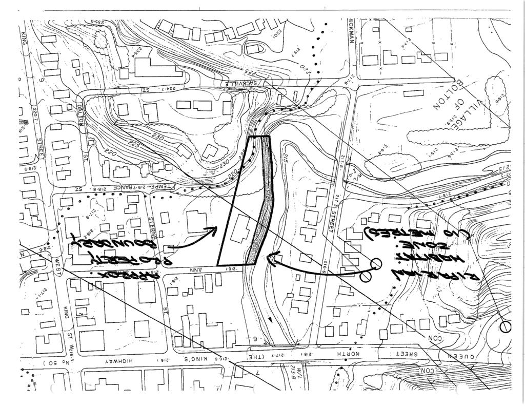
13 N41 18'05''E N45 51'20''W BH1 BH2 N45 25'0''W N45 55'55''W N44 28'50''E N41 06'10''E Legend: Client: Brookfield Homes (Ontario) Limited Project No.: G0 Drawing No.: 1 Drawn: DX Approved: SD Title: Borehole Location Plan Borehole Location Date: September 2018 Scale: N.T.S Project: Geotechnical Investigation Slope Stability Analysis for the Existing Slope 50 Ann Street, Bolton, Ontario Original Size: Letter Rev: SD

14 Drawing No. 2 Slope Stability Analysis of Existing Slope, Cross-Section A1-A1 Unit 57, 40 Vogell Road, Richmond Hill, ON Tel: Fax:

15 Drawing No. Slope Stability Analysis of Existing Slope, Cross-Section A-A Unit 57, 40 Vogell Road, Richmond Hill, ON Tel: Fax:

16 Drawing No. 4 Slope Stability Analysis of Existing Slope, Cross-Section B-B Unit 57, 40 Vogell Road, Richmond Hill, ON Tel: Fax:
17 ENCLOSURES
18 Enclosure 1A: Notes on Sample Descriptions 1. Each soil stratum is described according to the Modified Unified Soil Classification System. The compactness condition of cohesionless soils (SPT) and the consistency of cohesive soils (undrained shear strength) are defined according to Canadian Foundation Engineering Manual, 4 th Edition. Different soil classification systems may be used by others. Please note that a description of the soil stratums is based on visual and tactile examination of the samples augmented with field and laboratory test results, such as a grain size analysis and/or Atterberg Limits testing. Visual classification is not sufficiently accurate to provide exact grain sizing or precise differentiation between size classification systems. 2. Fill: Where fill is designated on the borehole log it is defined as indicated by the sample recovered during the boring process. The reader is cautioned that fills are heterogeneous in nature and variable in density or degree of compaction. The borehole description may therefore not be applicable as a general description of site fill materials. All fills should be expected to contain obstruction such as wood, large concrete pieces or subsurface basements, floors, tanks, etc., none of these may have been encountered in the boreholes. Since boreholes cannot accurately define the contents of the fill, test pits are recommended to provide supplementary information. Despite the use of test pits, the heterogeneous nature of fill will leave some ambiguity as to the exact composition of the fill. Most fills contain pockets, seams, or layers of organically contaminated soil. This organic material can result in the generation of methane gas and/or significant ongoing and future settlements. Fill at this site may have been monitored for the presence of methane gas and, if so, the results are given on the borehole logs. The monitoring process does not indicate the volume of gas that can be potentially generated nor does it pinpoint the source of the gas. These readings are to advise of the presence of gas only, and a detailed study is recommended for sites where any explosive gas/methane is detected. Some fill material may be contaminated by toxic/hazardous waste that renders it unacceptable for deposition in any but designated land fill sites; unless specifically stated the fill on this site has not been tested for contaminants that may be considered toxic or hazardous. This testing and a potential hazard study can be undertaken if requested. In most residential/commercial areas undergoing reconstruction, buried oil tanks are common and are generally not detected in a conventional preliminary geotechnical site investigation.. Till: The term till on the borehole logs indicates that the material originates from a geological process associated with glaciation. Because of this geological process the till must be considered heterogeneous in composition and as such may contain pockets and/or seams of material such as sand, gravel, silt or clay. Till often contains cobbles (60 to 200 mm) or boulders (over 200 mm). Contractors may therefore encounter cobbles and boulders during excavation, even if they are not indicated by the borings. It should be appreciated that normal sampling equipment cannot differentiate the size or type of any obstruction. Because of the horizontal and vertical variability of till, the sample description may be applicable to a very limited zone; caution is therefore essential when dealing with sensitive excavations or dewatering programs in till materials.
19 Enclosure 1B: Explanation of Terms Used in the Record of Boreholes Sample Type AS BS CS DO DS FS NR RC SC SH ST TO TP WS Auger sample Block sample Chunk sample Drive open Dimension type sample Foil sample No recovery Rock core Soil core Spoon sample Shelby tube Sample Slotted tube Thin-walled, open Thin-walled, piston Wash sample Penetration Resistance Standard Penetration Resistance (SPT), N: The number of blows by a 6.5 kg (140 lb) hammer dropped 760 mm (0 in) required to drive a 50 mm (2 in) drive open sampler for a distance of 00 mm (12 in). PM Samples advanced by manual pressure WR Samples advanced by weight of sampler and rod WH Samples advanced by static weight of hammer Dynamic Cone Penetration Resistance, Nd: The number of blows by a 6.5 kg (140 lb) hammer dropped 760 mm (0 in) to drive uncased a 50 mm (2 in) diameter, 60 o cone attached to A size drill rods for a distance of 00 mm (12 in). Piezo-Cone Penetration Test (CPT): An electronic cone penetrometer with a 60 degree conical tip and a projected end area of 10 cm² pushed through ground at a penetration rate of 2 cm/s. Measurement of tip resistance (Qt), porewater pressure (PWP) and friction along a sleeve are recorded electronically at 25 mm penetration intervals. Textural Classification of Soils (ASTM D2487) Classification Particle Size Boulders > 00 mm Cobbles 75 mm - 00 mm Gravel 4.75 mm - 75 mm Sand mm 4.75 mm Silt mm mm Clay <0.002 mm(*) (*) Canadian Foundation Engineering Manual (4 th Edition) Coarse Grain Soil Description (50% greater than mm) Terminology Proportion Trace 0-10% Some 10-20% Adjective (e.g. silty or sandy) 20-5% And (e.g. sand and gravel) > 5% Soil Description a) Cohesive Soils(*) Consistency Undrained Shear SPT N Value Strength (kpa) Very soft < Soft Firm Stiff Very stiff Hard >200 >0 (*) Hierarchy of Shear Strength prediction 1. Lab triaxial test 2. Field vane shear test. Lab. vane shear test 4. SPT N value 5. Pocket penetrometer b) Cohesionless Soils Compactness Condition (Formerly Relative Density) Very loose <4 Loose 4-10 Compact 10-0 Dense 0-50 Very dense >50 SPT N Value Soil Tests w Water content wp Plastic limit wl Liquid limit C Consolidation (oedometer) test CID Consolidated isotropically drained triaxial test CIU consolidated isotropically undrained triaxial test with porewater pressure measurement DR Relative density (specific gravity, Gs) DS Direct shear test ENV Environmental/ chemical analysis M Sieve analysis for particle size MH Combined sieve and hydrometer (H) analysis MPC Modified proctor compaction test SPC Standard proctor compaction test OC Organic content test U Unconsolidated Undrained Triaxial Test V Field vane (LV-laboratory vane test) γ Unit weight
20 LOG OF BOREHOLE BH1 1 OF 1 PROJECT: Geotechnical Investigation - Slope Stability Assessment for the Existing Slope CLIENT: Brookfield Homes (Ontario) Limited PROJECT LOCATION: 50 Ann Street, Bolton, Ontario DATUM: Geodetic BH LOCATION: See Borehole Location Plan SOIL PROFILE SAMPLES DYNAMIC PENETRATION TEST Natural REMARKS SPT Cone blows/0.m Plastic Moisture Liquid Limit Content Limit AND w P w w GRAIN SIZE L ELEV SHEAR STRENGTH (kpa) DISTRIBUTION DESCRIPTION DEPTH Unconfined Field Vane & Sensitivity WATER CONTENT (%) (%) (m) Quick Triaxial Penetrometer Lab Vane GR SA SI CL 0.0 TOPSOIL: (150 mm) FINE SANDY SILT: trace rootlets, brown, moist, loose Bentonite STRATA PLOT NUMBER 1 TYPE "N" BLOWS/0.m 5 GROUND WATER METHOD: Continuous Split Spoon FIELD ENGINEER: RR SAMPLE REVIEW: DX CHECKED: DL ELEVATION DRILLING DATA DIAMETER: 51 mm DATE: REF. NO.: G0 ENCL. NO.: 2 UNIT WT (kn/m ) SILT: trace to some sand, trace clay, brown, moist, compact to dense GEOPRO SOIL LOG G0 ADDITIONAL GEOTECHNICAL BOREHOLES FOR PROPOSED SLOPE STABILITY ANALYSIS LAB - DX.GPJ : END OF BOREHOLE DUE TO SPOON REFUSAL Notes: 1) Borehole was open and dry upon completion of drilling. 2) 8 mm dia. monitoring well was installed in borehole upon completion of drilling. Water Level Reading Date W. L Depth (mbgs) May 4, 2018 dry 46 Sand Screen 218 GRAPH GROUNDWATER ELEVATIONS, : Numbers refer =% Strain at Failure NOTES to Sensitivity 1st 2nd rd 4th Measurement
21 LOG OF BOREHOLE BH2 1 OF 1 PROJECT: Geotechnical Investigation - Slope Stability Assessment for the Existing Slope CLIENT: Brookfield Homes (Ontario) Limited PROJECT LOCATION: 50 Ann Street, Bolton, Ontario DATUM: Geodetic BH LOCATION: See Borehole Location Plan SOIL PROFILE SAMPLES DYNAMIC PENETRATION TEST Natural REMARKS SPT Cone blows/0.m Plastic Moisture Liquid Limit Content Limit AND w P w w GRAIN SIZE L ELEV SHEAR STRENGTH (kpa) DISTRIBUTION DESCRIPTION DEPTH Unconfined Field Vane & Sensitivity WATER CONTENT (%) (%) (m) Quick Triaxial Penetrometer Lab Vane GR SA SI CL 0.0 TOPSOIL: (165 mm) SILT: trace to some sand, trace clay, trace rootlets, seams/layers of clayey silt, laminated, brown, moist, loose STRATA PLOT NUMBER 1 TYPE "N" BLOWS/0.m 7 GROUND WATER METHOD: Continuous Split Spoon FIELD ENGINEER: RR SAMPLE REVIEW: DX CHECKED: DL ELEVATION DRILLING DATA DIAMETER: 51 mm DATE: REF. NO.: G0 ENCL. NO.: UNIT WT (kn/m ) FINE SAND AND SILT: layers of silt, seams of silty fine sand, brown, moist, very dense GEOPRO SOIL LOG G0 ADDITIONAL GEOTECHNICAL BOREHOLES FOR PROPOSED SLOPE STABILITY ANALYSIS LAB - DX.GPJ : END OF BOREHOLE DUE TO SPOON REFUSAL Notes: 1) Borehole was open and dry upon completion of drilling. GRAPH GROUNDWATER ELEVATIONS, : Numbers refer =% Strain at Failure NOTES to Sensitivity 1st 2nd rd 4th Measurement
22 FIGURES
 60 55 50 45 40 5 0 11 - GEOPRO_GRAIN_SIZE 16-1618G0 ADDITIONAL GEOTECHNICAL BOREHOLES FOR PROPOSED SLOPE")
23 100 U.S. SIEVE OPENING IN INCHES U.S. SIEVE NUMBERS HYDROMETER /4 1/2 / PAING WEIGHT (%) GEOPRO_GRAIN_SIZE G0 ADDITIONAL GEOTECHNICAL BOREHOLES FOR PROPOSED SLOPE STABILITY ANALYSIS LAB.GPJ : COBBLES 100 Specimen Identification 10 1 GRAIN SIZE (MM) medium Classification BH Specimen Identification GRAVEL coarse fine coarse D100 D60 SAND D0 BH D10 LOCATION: 50 Ann Street, Bolton, Ontario Unit 57, 40 Vogell Road, Richmond Hill, Ontario L4B N6 Tel: Fax: PROJECT NO.: G0 office@geoproconsulting.ca FIGURE NO.: 1 fine 0.1 %Gravel GRAIN SIZE DISTRIBUTION 0.01 SILT PROJECT: Additional Geotechnical Boreholes for Proposed Slope Stability Analysis LL %Sand SAMPLED ON: TESTED ON: CLAY PL PI Cc Cu %Silt %Clay
24 APPENDIX A
25
26
27
28
29
30
31
32
33
34

35 APPENDIX B

36 BH4 BH5 BH BH1 BH2 Client: Brookfield Homes (Ontario) Limited Project No.: Drawing No.: 1 BH BH1 Borehole Location Monitoring Well Location Drawn: AC Approved: DL Date: October 2016 Scale: As shown Title: Project: Borehole Location Plan Supplementary Geotechnical Investigation for Proposed Midrise Condominium Development, 50 Ann Street, Bolton, Ontario Original Size: Letter Rev: DL
37 LOG OF BOREHOLE BH1 1 OF PROJECT: Proposed Condominium Development CLIENT: Brookfield Homes (Ontario) Limited PROJECT LOCATION: 50 Ann Street, Bolton, Ontario DATUM: Geodetic BH LOCATION: See Borehole Location Plan (m) ELEV DEPTH SOIL PROFILE DESCRIPTION TOPSOIL (100 mm) FILL: sandy silt to silty sand, trace to some gravel, trace clay, trace rootlets, trace organics, dark brown, moist, compact FILL: silt, some clay, trace to some fine sand, brown, moist, very loose to loose STRATA PLOT NUMBER 1 2 SAMPLES TYPE "N" BLOWS 0. m 14 4 GROUND WATER CONDITIONS ELEVATION Concrete DRILLING DATA Method: Continuous Flight Auger - Auto Hammer Diameter: 155/205mm Date: Oct/06/2016 REF. NO.: ENCL NO.: 2 DYNAMIC CONE PENETRATION RESISTANCE PLOT NATURAL PLASTIC MOISTURE LIMIT CONTENT w P w w L SHEAR STRENGTH (kpa) FIELD VANE UNCONFINED & Sensitivity QUICK TRIAXIAL LAB VANE WATER CONTENT (%) LIQUID LIMIT POCKET PEN. (Cu) (kpa) NATURAL UNIT WT (kn/m ) REMARKS AND GRAIN SIZE DISTRIBUTION (%) GR SA SI CL CLAYEY SILT: trace to some sand, trace gravel, brown, moist, firm 4 7 Bentonite SILT: some clay, trace fine sand, containing interlayers of clayey silt, grey, wet, loose to dense 6 14 W. L m Nov 21 01, zones of clayey silt 7 9 Sand Screen CLAYEY SILT: trace fine sand, containing interlayers of silt, grey, wet to saturated, firm SILT: some clay, trace fine sand, containing interlayers of clayey silt, grey, wet, loose Dynamic Cone starts at m Natural 204 Pack Continued Next Page GROUNDWATER ELEVATIONS Measurement 1st 2nd rd 4th GRAPH NOTES 202, : Numbers refer to Sensitivity =% Strain at Failure
38 LOG OF BOREHOLE BH1 2 OF 2 PROJECT: Proposed Condominium Development CLIENT: Brookfield Homes (Ontario) Limited PROJECT LOCATION: 50 Ann Street, Bolton, Ontario DATUM: Geodetic BH LOCATION: See Borehole Location Plan (m) ELEV DEPTH SOIL PROFILE DESCRIPTION STRATA PLOT NUMBER SAMPLES TYPE "N" BLOWS 0. m GROUND WATER CONDITIONS ELEVATION DRILLING DATA Method: Continuous Flight Auger - Auto Hammer Diameter: 155/205mm Date: Oct/06/2016 REF. NO.: ENCL NO.: 2 DYNAMIC CONE PENETRATION RESISTANCE PLOT NATURAL PLASTIC MOISTURE LIMIT CONTENT w P w w L SHEAR STRENGTH (kpa) FIELD VANE UNCONFINED & Sensitivity QUICK TRIAXIAL LAB VANE WATER CONTENT (%) LIQUID LIMIT POCKET PEN. (Cu) (kpa) NATURAL UNIT WT (kn/m ) REMARKS AND GRAIN SIZE DISTRIBUTION (%) GR SA SI CL END OF BOREHOLE Notes: 1) Water encountered at a depth of 4.6 m below ground surface (mbgs) during drilling. 2) Water was at a depth of 2.4 mbgs upon completion of drilling. ) 51 mm dia. monitoring well installed in borehole upon completion of drilling. Water Level Readings Date W.L. Depth (mbgs) Nov GROUNDWATER ELEVATIONS 1st 2nd rd 4th Measurement GRAPH NOTES, : Numbers refer to Sensitivity =% Strain at Failure
39 LOG OF BOREHOLE BH2 1 OF PROJECT: Proposed Condominium Development CLIENT: Brookfield Homes (Ontario) Limited PROJECT LOCATION: 50 Ann Street, Bolton, Ontario DATUM: Geodetic BH LOCATION: See Borehole Location Plan (m) ELEV DEPTH SOIL PROFILE DESCRIPTION GRANULAR BASE/ SUBBASE (100 mm) FILL: sandy silt to silty sand, trace to some gravel, trace clay, trace organics, brown, moist, compact SILT: trace clay, trace sand, containing seams of fine sand, brown, wet, compact CLAYEY SILT: trace sand, containing layers/zones of silt, grey, wet, stiff SILT: some clay, trace fine sand, containing interlayers of clayey silt, grey, wet, loose to compact STRATA PLOT NUMBER SAMPLES TYPE "N" BLOWS 0. m GROUND WATER CONDITIONS ELEVATION Concrete Bentonite 21 DRILLING DATA Method: Continuous Flight Auger - Auto Hammer Diameter: 155/205mm Date: Oct/14/2016 REF. NO.: ENCL NO.: DYNAMIC CONE PENETRATION RESISTANCE PLOT NATURAL PLASTIC MOISTURE LIMIT CONTENT w P w w L SHEAR STRENGTH (kpa) FIELD VANE UNCONFINED & Sensitivity QUICK TRIAXIAL LAB VANE WATER CONTENT (%) LIQUID LIMIT POCKET PEN. (Cu) (kpa) NATURAL UNIT WT (kn/m ) REMARKS AND GRAIN SIZE DISTRIBUTION (%) GR SA SI CL Sand 209 Screen CLAYEY SILT: trace fine sand, containing interlayers of silt, grey, wet to saturated, stiff SILT: trace to some clay, trace fine sand, containing interlayers of clayey silt, grey, saturated, loose Dynamic Cone starts at m Natural Pack Continued Next Page GROUNDWATER ELEVATIONS Measurement 1st 2nd rd 4th GRAPH NOTES 202, : Numbers refer to Sensitivity =% Strain at Failure
40 LOG OF BOREHOLE BH2 2 OF 2 PROJECT: Proposed Condominium Development CLIENT: Brookfield Homes (Ontario) Limited PROJECT LOCATION: 50 Ann Street, Bolton, Ontario DATUM: Geodetic BH LOCATION: See Borehole Location Plan (m) ELEV DEPTH SOIL PROFILE DESCRIPTION STRATA PLOT NUMBER SAMPLES TYPE "N" BLOWS 0. m GROUND WATER CONDITIONS ELEVATION DRILLING DATA Method: Continuous Flight Auger - Auto Hammer Diameter: 155/205mm Date: Oct/14/2016 REF. NO.: ENCL NO.: DYNAMIC CONE PENETRATION RESISTANCE PLOT NATURAL PLASTIC MOISTURE LIMIT CONTENT w P w w L SHEAR STRENGTH (kpa) FIELD VANE UNCONFINED & Sensitivity QUICK TRIAXIAL LAB VANE WATER CONTENT (%) LIQUID LIMIT POCKET PEN. (Cu) (kpa) NATURAL UNIT WT (kn/m ) REMARKS AND GRAIN SIZE DISTRIBUTION (%) GR SA SI CL END OF BOREHOLE Notes: 1) Water encountered at a depth of 4.9 m below ground surface (mbgs) during drilling. 2) Borehole caved-in at a depth of 9.1 mbgs upon completion of drilling. GROUNDWATER ELEVATIONS 1st 2nd rd 4th Measurement GRAPH NOTES, : Numbers refer to Sensitivity =% Strain at Failure
41 LOG OF BOREHOLE BH 1 OF PROJECT: Proposed Condominium Development CLIENT: Brookfield Homes (Ontario) Limited PROJECT LOCATION: 50 Ann Street, Bolton, Ontario DATUM: Geodetic BH LOCATION: See Borehole Location Plan (m) ELEV DEPTH SOIL PROFILE DESCRIPTION GRANULAR BASE/ SUBBASE (250 mm) FILL: sandy silt, trace clay, trace gravel, organic odour, brown, moist, compact FILL: sand, trace to some silt, containing fabric pieces, containing plastic pieces, brown, moist, compact FILL: clayey silt, trace sand, trace gravel, brown, moist, stiff FILL: sandy silt to silty sand, trace clay, trace gravel, containing layers of clayey silt, containing plastic pieces, brown, wet, loose CLAYEY SILT: trace fine sand, containing layers/ zones of silt, grey, wet, stiff STRATA PLOT NUMBER SAMPLES TYPE "N" BLOWS 0. m GROUND WATER CONDITIONS ELEVATION DRILLING DATA Method: Continuous Flight Auger - Auto Hammer Diameter: 155/205mm Date: Oct/1/2016 REF. NO.: ENCL NO.: 4 DYNAMIC CONE PENETRATION RESISTANCE PLOT NATURAL PLASTIC MOISTURE LIMIT CONTENT w P w w L SHEAR STRENGTH (kpa) FIELD VANE UNCONFINED & Sensitivity QUICK TRIAXIAL LAB VANE WATER CONTENT (%) LIQUID LIMIT POCKET PEN. (Cu) (kpa) NATURAL UNIT WT (kn/m ) REMARKS AND GRAIN SIZE DISTRIBUTION (%) GR SA SI CL SILT: some clay, trace fine sand, containing interlayers of clayey silt, grey, wet, loose CLAYEY SILT: trace fine sand, zones of silt, grey, wet, stiff SILT: some clay, trace fine sand, containing interlayers of clayey silt, grey, wet, loose CLAYEY SILT: trace fine sand, containing interlayers of silt, grey, wet, stiff SILT: some clay, trace fine sand, containing interlayers of clayey silt, grey, wet, compact END OF BOREHOLE Notes: 1) Water encountered at a depth of 2.4 m below ground surface (mbgs) during drilling. 2) Water was at a depth of.0 mbgs upon completion of drilling. ) Borehole caved-in at a depth of 11.6 mbgs upon completion of drilling GROUNDWATER ELEVATIONS 1st 2nd rd 4th Measurement GRAPH NOTES, : Numbers refer to Sensitivity =% Strain at Failure
42 LOG OF BOREHOLE BH4 1 OF PROJECT: Proposed Condominium Development CLIENT: Brookfield Homes (Ontario) Limited PROJECT LOCATION: 50 Ann Street, Bolton, Ontario DATUM: Geodetic BH LOCATION: See Borehole Location Plan (m) ELEV DEPTH SOIL PROFILE DESCRIPTION ASPHALT (100 mm) GRANULAR BASE/SUBBASE (470 mm) FILL: sand and silt, some gravel, brown, moist, FILL: silty sand, trace gravel, containing pockets of sandy silt, brown, moist, dense FILL: sandy silt, trace clay, trace gravel, brown, moist, dense FILL: clayey silt, trace sand, trace gravel, trace organics, containing wood pieces, dark brown to grey, moist, firm FILL: fine sandy silt to fine sand and silt, trace clay, brown to grey, wet, very loose CLAYEY SILT: trace fine sand, containing interlayers of silt, grey, wet, stiff SILT: some clay, trace fine sand, containing interlayers of clayey silt, grey, wet, loose to compact STRATA PLOT NUMBER SAMPLES TYPE AS "N" BLOWS 0. m GROUND WATER CONDITIONS ELEVATION DRILLING DATA Method: Continuous Flight Auger - Auto Hammer Diameter: 155/205mm Date: Oct/1/2016 REF. NO.: ENCL NO.: 5 DYNAMIC CONE PENETRATION RESISTANCE PLOT NATURAL PLASTIC MOISTURE LIMIT CONTENT w P w w L SHEAR STRENGTH (kpa) FIELD VANE UNCONFINED & Sensitivity QUICK TRIAXIAL LAB VANE WATER CONTENT (%) LIQUID LIMIT POCKET PEN. (Cu) (kpa) NATURAL UNIT WT (kn/m ) REMARKS AND GRAIN SIZE DISTRIBUTION (%) GR SA SI CL containing zones of clayey silt Dynamic Cone starts at 12.8 m END OF BOREHOLE Notes: 1) Water encountered at a depth of Continued Next Page GROUNDWATER ELEVATIONS Measurement 1st 2nd rd 4th GRAPH NOTES, : Numbers refer to Sensitivity =% Strain at Failure
43 LOG OF BOREHOLE BH4 2 OF 2 PROJECT: Proposed Condominium Development CLIENT: Brookfield Homes (Ontario) Limited PROJECT LOCATION: 50 Ann Street, Bolton, Ontario DATUM: Geodetic BH LOCATION: See Borehole Location Plan (m) ELEV DEPTH SOIL PROFILE DESCRIPTION 2.4 m below ground surface (mbgs) during drilling. 2) Water was at a depth of 0.9 mbgs upon completion of drilling. STRATA PLOT NUMBER SAMPLES TYPE "N" BLOWS 0. m GROUND WATER CONDITIONS ELEVATION DRILLING DATA Method: Continuous Flight Auger - Auto Hammer Diameter: 155/205mm Date: Oct/1/2016 REF. NO.: ENCL NO.: 5 DYNAMIC CONE PENETRATION RESISTANCE PLOT NATURAL PLASTIC MOISTURE LIMIT CONTENT w P w w L SHEAR STRENGTH (kpa) FIELD VANE UNCONFINED & Sensitivity QUICK TRIAXIAL LAB VANE WATER CONTENT (%) LIQUID LIMIT POCKET PEN. (Cu) (kpa) NATURAL UNIT WT (kn/m ) REMARKS AND GRAIN SIZE DISTRIBUTION (%) GR SA SI CL GROUNDWATER ELEVATIONS 1st 2nd rd 4th Measurement GRAPH NOTES, : Numbers refer to Sensitivity =% Strain at Failure
44 LOG OF BOREHOLE BH5 1 OF PROJECT: Proposed Condominium Development CLIENT: Brookfield Homes (Ontario) Limited PROJECT LOCATION: 50 Ann Street, Bolton, Ontario DATUM: Geodetic BH LOCATION: See Borehole Location Plan (m) ELEV DEPTH SOIL PROFILE DESCRIPTION ASPHALT (140 mm) GRANULAR BASE/SUBBASE (280 mm) FILL: gravelly sand, trace to some silt, containing pockets of clayey silt, brown, moist FILL: silt, trace to some clay, trace sand, trace gravel, containing zones of clayey silt, containing red brick fragments, brown to grey, moist, loose FILL: clayey silt, trace to some sand, trace gravel, containing layers of silt, containing wood pieces, brown, moist, firm FILL: fine sand and silt, trace clay, brown, moist to wet, very loose STRATA PLOT NUMBER SAMPLES TYPE AS "N" BLOWS 0. m GROUND WATER CONDITIONS ELEVATION Concrete DRILLING DATA Method: Continuous Flight Auger - Auto Hammer Diameter: 155/205mm Date: Oct/1/2016 REF. NO.: ENCL NO.: 6 DYNAMIC CONE PENETRATION RESISTANCE PLOT NATURAL PLASTIC MOISTURE LIMIT CONTENT w P w w L SHEAR STRENGTH (kpa) FIELD VANE UNCONFINED & Sensitivity QUICK TRIAXIAL LAB VANE WATER CONTENT (%) LIQUID LIMIT POCKET PEN. (Cu) (kpa) NATURAL UNIT WT (kn/m ) REMARKS AND GRAIN SIZE DISTRIBUTION (%) GR SA SI CL SILT: some clay, trace fine sand, containing interlayers of clayey silt, containing layers of silty fine sand, grey, wet, loose CLAYEY SILT: trace fine sand, containing interlayers of silt, grey, wet, stiff Bentonite zones of silt SILT: some clay, trace fine sand, containing interlayers of clayey silt, grey, wet to saturated, loose to compact Sand Screen Dynamic Cone starts at 12.8 m Natural Pack END OF BOREHOLE Notes: 1) Water encountered at a depth of Continued Next Page GROUNDWATER ELEVATIONS Measurement 1st 2nd rd 4th GRAPH NOTES 202, : Numbers refer to Sensitivity =% Strain at Failure
45 LOG OF BOREHOLE BH5 2 OF 2 PROJECT: Proposed Condominium Development CLIENT: Brookfield Homes (Ontario) Limited PROJECT LOCATION: 50 Ann Street, Bolton, Ontario DATUM: Geodetic BH LOCATION: See Borehole Location Plan (m) ELEV DEPTH SOIL PROFILE DESCRIPTION 1.2 m below ground surface (mbgs) during drilling. 2) Water was at a depth of.0 mbgs upon completion of drilling. STRATA PLOT NUMBER SAMPLES TYPE "N" BLOWS 0. m GROUND WATER CONDITIONS ELEVATION DRILLING DATA Method: Continuous Flight Auger - Auto Hammer Diameter: 155/205mm Date: Oct/1/2016 REF. NO.: ENCL NO.: 6 DYNAMIC CONE PENETRATION RESISTANCE PLOT NATURAL PLASTIC MOISTURE LIMIT CONTENT w P w w L SHEAR STRENGTH (kpa) FIELD VANE UNCONFINED & Sensitivity QUICK TRIAXIAL LAB VANE WATER CONTENT (%) LIQUID LIMIT POCKET PEN. (Cu) (kpa) NATURAL UNIT WT (kn/m ) REMARKS AND GRAIN SIZE DISTRIBUTION (%) GR SA SI CL GROUNDWATER ELEVATIONS 1st 2nd rd 4th Measurement GRAPH NOTES, : Numbers refer to Sensitivity =% Strain at Failure
46 LIMITATIONS TO THE REPORT This report is intended solely for the Client named. The report is prepared based on the work has been undertaken in accordance with normally accepted geotechnical engineering practices in Ontario. The comments and recommendations given in this report are based on information determined at the limited number of the test hole and test pit locations. The boundaries between the various strata as shown on the borehole logs are based on non-continuous sampling and represent an inferred transition between the various strata and their lateral continuation rather than a precise plane of geological change. Subsurface and groundwater conditions between and beyond the test holes and test pits may differ significantly from those encountered at the test hole and test pit locations. The benchmark and elevations used in this report are primarily to establish relative elevation differences between the test hole and test pit locations and should not be used for other purposes, such as grading, excavating, planning, development, etc. It should be noted that the results of the designated substance and chemical analysis refer only to the sample analyzed which was obtained from specific sampling location and sampling depth, and the presence of designated substance and soil chemistry may vary between and beyond the location and depth of the sample taken. Please note that the level of chemical testing outlined herein is meant to provide a broad indication of soil quality based on the limited soil samples tested. The analytical results contained in this report should not be considered a warranty with respect to the soil quality or the use of the soil for any specific purpose or the acceptability of the soils for any excess soil receiving sites. The report reflects our best judgment based on the information available to GeoPro Consulting Limited at the time of preparation. Unless otherwise agreed in writing by GeoPro Consulting Limited, it shall not be used to express or imply warranty as to any other purposes. No portion of this report shall be used as a separate entity, it is written to be read in its entirety. The information contained herein in no way reflects on the environment aspects of the project, unless otherwise stated. The design recommendations given in this report are applicable only to the project designed and constructed completely in accordance with the details stated in this report. Otherwise, our responsibility is limited to interpreting the subsurface information at the borehole or test pit locations. Should any comments and recommendations provided in this report be made on any construction related issues, they are intended only for the guidance of the designers. The number of test holes and test pits may not be sufficient to determine all the factors that may affect construction activities, methods and costs. Such as, the thickness of surficial topsoil or fill layers may vary significantly and unpredictably; the amount of the cobbles and boulders may vary significantly than what described in the report; unexpected water bearing zones/layers with various thickness and extent may be encountered in the fill and native soils. The contractors bidding on this project or undertaking the construction should, therefore, make their own interpretation of the factual information presented and make their own conclusions as to how the subsurface conditions may affect their work and determine the proper construction methods. Any use which a third party makes of this report, or any reliance on or decisions to be made based on it, are the responsibility of such third parties. GeoPro Consulting Limited accepts no responsibility for damages, if any, suffered by any third party as a result of decisions made or actions based on this report. We accept no responsibility for any decisions made or actions taken as a result of this report unless we are specifically advised of and participate in such action, in which case our responsibility will be as agreed to at that time. Unit 57, 40 Vogell Road, Richmond Hill, Ontario L4B N6 Tel: Fax:
REPORT ON SLOPE STABILITY INVESTIGATION DON MILLS ROAD AND EGLINTON AVENUE EAST TORONTO, ONTARIO. Prepared for:
 REPORT ON SLOPE STABILITY INVESTIGATION DON MILLS ROAD AND EGLINTON AVENUE EAST TORONTO, ONTARIO Prepared for: TORONTO AND REGION CONSERVATION AUTHORITY Prepared By: SIRATI & PARTNERS CONSULTANTS LIMITED
B-1 BORE LOCATION PLAN. EXHIBIT Drawn By: 115G BROOKS VETERINARY CLINIC CITY BASE LANDING AND GOLIAD ROAD SAN ANTONIO, TEXAS.
 N B-1 SYMBOLS: Exploratory Boring Location Project Mngr: BORE LOCATION PLAN Project No. GK EXHIBIT Drawn By: 115G1063.02 GK Scale: Checked By: 1045 Central Parkway North, Suite 103 San Antonio, Texas 78232
 Project: ITHACA-TOMPKINS REGIONAL AIRPORT EXPANSION Project Location: ITHACA, NY Project Number: 218-34 Key to Soil Symbols and Terms TERMS DESCRIBING CONSISTENCY OR CONDITION COARSE-GRAINED SOILS (major
Boreholes. Implementation. Boring. Boreholes may be excavated by one of these methods: 1. Auger Boring 2. Wash Boring 3.
 Implementation Boreholes 1. Auger Boring 2. Wash Boring 3. Rotary Drilling Boring Boreholes may be excavated by one of these methods: 4. Percussion Drilling The right choice of method depends on: Ground
General. DATE December 10, 2013 PROJECT No TO Mary Jarvis Urbandale/Riverside South Development Corporation
 DATE December 10, 201 PROJECT No. 10-1121-0260- TO Mary Jarvis Urbandale/Riverside South Development Corporation CC Justin Robitaille, Urbandale Jonathan Párraga, J.L. Richards & Associates Limited FROM
SLOPE STABILITY ASSESSMENT PROPOSED RESIDENTIAL SUBDIVISION 161 LAKESHORE ROAD EAST TOWN OF THE BLUE MOUNTAINS, ONTARIO
 SLOPE STABILITY ASSESSMENT PROPOSED RESIDENTIAL SUBDIVISION 161 LAKESHORE ROAD EAST TOWN OF THE BLUE MOUNTAINS, ONTARIO PETO MacCALLUM LTD. 19 CHURCHILL DRIVE BARRIE, ONTARIO L4N 8Z5 PHONE: (705) 734-3900
 Photo 1 - Southerly view across 2700 parking lot toward existing building. Multi-residential building borders western side of property in upper right of view. Photo 2 - Southerly view across 2750 parking
Appendix H. Geotechnical Investigation Report. Krosno Creek Flood Reduction Project PROJECT FILE REPORT CITY OF PICKERING
 Krosno Creek Flood Reduction Project PROJECT FILE REPORT CITY OF PICKERING Appendix H Geotechnical Investigation Report TMIG THE MUNICIPAL INFRASTRUCTURE GROUP LTD Report on Geotechnical Investigation
Pierce County Department of Planning and Land Services Development Engineering Section
 Page 1 of 7 Pierce County Department of Planning and Land Services Development Engineering Section PROJECT NAME: DATE: APPLICATION NO.: PCDE NO.: LANDSLIDE HAZARD AREA (LHA) GEOLOGICAL ASSESSMENT REPORT
Depth (ft) USCS Soil Description TOPSOIL & FOREST DUFF
 USCS Soil Description TOPSOIL & FOREST DUFF") Test Pit No. TP-6 Location: Latitude 47.543003, Longitude -121.980441 Approximate Ground Surface Elevation: 1,132 feet Depth (ft) USCS Soil Description 0 1.5 1.5 5.0 SM 5.0 8.0 SM Loose to medium dense,
Test Pit No. TP-6 Location: Latitude 47.543003, Longitude -121.980441 Approximate Ground Surface Elevation: 1,132 feet Depth (ft) USCS Soil Description 0 1.5 1.5 5.0 SM 5.0 8.0 SM Loose to medium dense,
Chapter 12 Subsurface Exploration
 Page 12 1 Chapter 12 Subsurface Exploration 1. The process of identifying the layers of deposits that underlie a proposed structure and their physical characteristics is generally referred to as (a) subsurface
ENCE 3610 Soil Mechanics. Site Exploration and Characterisation Field Exploration Methods
 ENCE 3610 Soil Mechanics Site Exploration and Characterisation Field Exploration Methods Geotechnical Involvement in Project Phases Planning Design Alternatives Preparation of Detailed Plans Final Design
APPENDIX A. Borehole Logs Explanation of Terms and Symbols
 APPENDIX A Borehole Logs Explanation of Terms and Symbols Page 153 of 168 EXPLANATION OF TERMS AND SYMBOLS The terms and symbols used on the borehole logs to summarize the results of field investigation
Civil Engineering, Surveying and Environmental Consulting WASP0059.ltr.JLS.Mich Ave Bridge Geotech.docx
 2365 Haggerty Road South * Canton, Michigan 48188 P: 734-397-3100 * F: 734-397-3131 * www.manniksmithgroup.com August 29, 2012 Mr. Richard Kent Washtenaw County Parks and Recreation Commission 2330 Platt
APPENDIX A GEOTECHNICAL REPORT
 The City of Winnipeg Bid Opportunity No. 529-2017 Template Version: C420170317 - RW APPENDIX A GEOTECHNICAL REPORT Quality Engineering Valued Relationships KGS Group 2017 Industrial Street Rehabilitation
DATA REPORT GEOTECHNICAL INVESTIGATION GALVESTON CRUISE TERMINAL 2 GALVESTON, TEXAS
 DATA REPORT GEOTECHNICAL INVESTIGATION GALVESTON CRUISE TERMINAL 2 GALVESTON, TEXAS SUBMITTED TO PORT OF GALVESTON 123 ROSENBERG AVENUE, 8TH FLOOR GALVESTON, TEXAS 77553 BY HVJ ASSOCIATES, INC. HOUSTON,
ADDENDUM 1 FISHER SLOUGH RESTORATION PROJECT SKAGIT COUNTY, WASHINGTON
 F I N A L A D D E N D U M 1 R E P O R T ADDENDUM 1 FISHER SLOUGH RESTORATION PROJECT SKAGIT COUNTY, WASHINGTON REPORT OF GEOTECHNICAL INVESTIGATION URS JOB NO. 3376186 Prepared for Tetra Tech Inc. 142
ATTACHMENT A PRELIMINARY GEOTECHNICAL SUMMARY
 ATTACHMENT A PRELIMINARY GEOTECHNICAL SUMMARY Kevin M. Martin, P.E. KMM Geotechnical Consultants, LLC 7 Marshall Road Hampstead, NH 0384 603-489-6 (p)/ 603-489-8 (f)/78-78-4084(m) kevinmartinpe@aol.com
Appendix A. Producer Statement Advisory Note
 Appendix A Producer Statement Advisory Note Ref. No. 17095 26 May 2017 PRODUCER STATEMENT CONSTRUCTION REVIEW (PS4) IMPORTANT ADVISORY NOTE The Building Consent Authority (BCA) frequently requires Producer
Hydro One (Sept 2014) Hydro One (Sept 2014) Hydro One (Sept 2014)
 Hydro One (Sept 2014) Hydro One (Sept 2014)") TABLE 1 WELL CONSTRUCTION DETAILS MOE WWR No Well ID Location Installation Date Status Easting Coordinates Northing Source Elevation Screened Interval Screened Material Borehole Well Stick-up Ground Top
TABLE 1 WELL CONSTRUCTION DETAILS MOE WWR No Well ID Location Installation Date Status Easting Coordinates Northing Source Elevation Screened Interval Screened Material Borehole Well Stick-up Ground Top
Terraprobe Consulting Geotechnical & Environmental Engineering Construction Materials Inspection & Testing
 Terraprobe Consulting Geotechnical & Environmental Engineering Construction Materials Inspection & Testing GEOTECHNICAL INVESTIGATION BLOCKS TO PIER HAMILTON, ONTARIO PREPARED FOR: City of Hamilton Waterfront
The process of determining the layers of natural soil deposits that will underlie a proposed structure and their physical properties is generally
 The process of determining the layers of natural soil deposits that will underlie a proposed structure and their physical properties is generally referred to as sub surface investigation 2 1 For proper
patersongroup Design for Earthquakes Consulting Engineers May 19, 2016 File: PG3733-LET.01
 patersongroup May 19, 2016 File: PG3733-LET.01 Hydro Ottawa Limited c/o Cresa Toronto 170 University Avenue, Suite 1 Toronto, Ontario M5H 3B3 Attention: Ms. Barbara Wright Consulting Engineers 154 Colonnade
Gotechnical Investigations and Sampling
 Gotechnical Investigations and Sampling Amit Prashant Indian Institute of Technology Gandhinagar Short Course on Geotechnical Investigations for Structural Engineering 12 14 October, 2017 1 Purpose of
16 January 2018 Job Number: RICHARD NEWMAN C\- CLARK FORTUNE MCDONALD AND ASSOCIATES PO BOX 553 QUEENSTOWN
 16 January 2018 Job Number: 50595 RICHARD NEWMAN C\- CLARK FORTUNE MCDONALD AND ASSOCIATES PO BOX 553 QUEENSTOWN CHANSEN@CFMA.CO.NZ STORMWATER DISPOSAL ASSESSMENT Dear Richard, RDAgritech were requested
Preliminary Geotechnical Investigation Cadiz / Trigg County I-24 Business Park. Cadiz, Kentucky
 Environmental & Geoscience, LLC 834 Madisonville Road Hopkinsville, KY 440 70.44.000 FAX 70.44.8300 www.wedrill.com A member of Trinity Energy & Infrastructure Group, LLC Preliminary Geotechnical Investigation
 SOIL CLASSIFICATION CHART COARSE-GRAINED SOILS MORE THAN 50% RETAINED ON NO.200 SIEVE FINE-GRAINED SOILS 50% OR MORE PASSES THE NO.200 SIEVE PRIMARY DIVISIONS GRAVELS MORE THAN 50% OF COARSE FRACTION RETAINED
Field Exploration. March 31, J-U-B ENGINEERS, Inc. 115 Northstar Avenue Twin Falls, Idaho Attn: Mr. Tracy Ahrens, P. E. E:
 March 31, 201 11 Northstar Avenue 83301 Attn: Mr. Tracy Ahrens, P. E. E: taa@jub.com Re: Geotechnical Data Report Preliminary Phase 1 Field Exploration Revision No. 1 Proposed Rapid Infiltration Basin
GEOTECHNICAL INVESTIGATION REPORT
 GEOTECHNICAL INVESTIGATION REPORT SOIL INVESTIGATION REPORT FOR STATIC TEST FACILITY FOR PROPELLANTS AT BDL, IBRAHIMPATNAM. Graphics Designers, M/s Architecture & Engineering 859, Banjara Avenue, Consultancy
SITE INVESTIGATION 1
 SITE INVESTIGATION 1 Definition The process of determining the layers of natural soil deposits that will underlie a proposed structure and their physical properties is generally referred to as site investigation.
3.0 SUMMARY OF FINDINGS
 AECOM 500 W Jefferson St. Suite 1600 Louisville, KY 40202 www.aecom.com 502-569-2301 tel 502-569-2304 fax October 17, 2018 Big Rivers Electric Corporation Sebree Generating Station 9000 Highway 2096 Robards,
Slope Stability Assessment Proposed Development 4401 Fallowfield Road Lands Ottawa, Ontario Rev-02
 REPORT August 2014 REPORT ON Slope Stability Assessment Proposed Development 4401 Fallowfield Road Lands Ottawa, Ontario Submitted to: DCR Phoenix Homes 18 Bentley Avenue Ottawa, Ontario K2E 6T8 Report
CONTENTS. 1. GeneralsG Field Investigation WorkG Laboratory Testing Work Surface Soil Description-- 7.
 CONTENTS Page 1. GeneralsG 4 2. Field Investigation WorkG 4 3. Laboratory Testing Work--- 5 4. Surface Soil Description-- 7 Appendix A Borehole Location Plan 11 Soil Profile-- 15 Bore Logs--=---- 18 Appendix
APPENDIX C HYDROGEOLOGIC INVESTIGATION
 Figure B-5.7 Figure B-5.8 Preliminary Geotechnical and Environmental Report Appendix C Hydrogeologic Investigation APPENDIX C HYDROGEOLOGIC INVESTIGATION December 21, 2011 WESTSIDE SUBWAY EXTENSION PROJECT
GEOTECHNICAL INVESTIGATION. Proposed Douglas Street Bus Lane
 May, 0 GEOTECHNICAL INVESTIGATION Proposed Douglas Street Bus Lane Submitted to: Greg Smith P.Eng. Senior Transportation Engineer Urban Systems Ltd. 0- Homer Street Vancouver, BC V6B W9 REPORT Report Number:
Geotechnical Data Report
 Geotechnical Data Report Downtown Greenville Future Conveyance Study December 1, 2015 Terracon Project No. 86155032 Prepared for: Prepared by: Terracon Consultants, Inc. December 1, 2015 561 Mauldin Road
LEGEND BUSINESS ZONE NORTH OF AGRESEARCH BOREHOLE CPT SEISMIC CPT AUGER SCALE. Powells Road TEST PIT AGRESEARCH INNOVATION PARK. Hamilton Ring Road
 LEGEND ra R aku Ru BUSINESS ZONE NORTH OF Powells Road oad AGRESEARCH BOREHOLE CPT SEISMIC CPT AUGER SCALE 3 mm TEST PIT AS121 SCPT12 TP18 BH13 TP15 2 AS125 AS126 TP14 BH12 AGRESEARCH CPT13 TP17 INNOVATION
APPENDIX C. Borehole Data
 APPENDIX C Borehole Data MAJOR DIVISIONS SOIL CLASSIFICATION CHART SYMBOLS GRAPH LETTER TYPICAL DESCRIPTIONS ADDITIONAL MATERIAL
8.1. What is meant by the shear strength of soils? Solution 8.1 Shear strength of a soil is its internal resistance to shearing stresses.
 8.1. What is meant by the shear strength of soils? Solution 8.1 Shear strength of a soil is its internal resistance to shearing stresses. 8.2. Some soils show a peak shear strength. Why and what type(s)
Minnesota Department of Transportation Geotechnical Section Cone Penetration Test Index Sheet 1.0 (CPT 1.0)
") This Cone Penetration Test (CPT) Sounding follows ASTM D 5778 and was made by ordinary and conventional methods and with care deemed adequate for the Department's design purposes. Since this sounding was
This Cone Penetration Test (CPT) Sounding follows ASTM D 5778 and was made by ordinary and conventional methods and with care deemed adequate for the Department's design purposes. Since this sounding was
B-1 SURFACE ELEVATION
 5A 5B LOGGED BY El. S. Bhangoo DRILLING CONTRACTOR Pitcher Drilling DRILLING METHOD Rotary Wash BEGIN DATE 12-14-12 SAMPLER TYPE(S) AND SIZE(S) (ID) SPT, MC BOREHOLE BACKFILL AND COMPLETION COMPLETION
CENTRAL REGION GEOHAZARDS RISK ASSESSMENT SITE INSPECTION FORM
 SITE NUMBER AND NAME C55 H861:02 Slide LEGAL DESCRIPTION NW 14-40-14-W4 CENTRAL REGION GEOHAZARDS RISK ASSESSMENT SITE INSPECTION FORM HIGHWAY & KM NAD 83 COORDINATES N 5811217 E 437291 PREVIOUS INSPECTION
Reference No S072 APRIL 2012
 A REPORT TO SOLMAR DEVELOPMENT CORP. A PRELIMINARY SOIL INVESTIGATION FOR PROPOSED SUBDIVISION DEVELOPMENT NORTHEAST OF SIDEROAD 5 AND 0 LINE TOWN OF ERIN Reference No. 202-S072 APRIL 202 DISTRIBUTION
ENGINEERING ASSOCIATES
 July 16, 211 Vista Design, Inc. 11634 Worcester Highway Showell, Maryland 21862 Attention: Reference: Dear Mr. Polk: Mr. Richard F. Polk, P.E. Geotechnical Engineering Report Charles County RFP No. 11-9
10. GEOTECHNICAL EXPLORATION PROGRAM
 Geotechnical site investigations should be conducted in multiple phases to obtain data for use during the planning and design of the tunnel system. Geotechnical investigations typically are performed in
Minnesota Department of Transportation Geotechnical Section Cone Penetration Test Index Sheet 1.0 (CPT 1.0)
") This Cone Penetration Test (CPT) Sounding follows ASTM D 778 and was made by ordinary and conventional methods and with care deemed adequate for the Department's design purposes. Since this sounding was
This Cone Penetration Test (CPT) Sounding follows ASTM D 778 and was made by ordinary and conventional methods and with care deemed adequate for the Department's design purposes. Since this sounding was
Appendix F Laboratory test results
 Appendix F Laboratory test results SOIL AND ROCK SAMPLE ANALYSIS LABORATORY TEST REPORT To: Bord Gais Copy: Orla Smyth (kkidd@bge.ie) From: Stephen Watson Laboratory Manager Causeway Geotech Ltd Tel: +44(0)2827666640
SI Planning & Laboratory Testing for Hill-Site Development
 SI Planning & Laboratory Testing for Hill-Site Development 21 April 2009 IEM Penang Ir. Tan Yean Chin G&P Geotechnics Sdn Bhd Cameron Highlands, 1961 Genting Highland Tower 1993 Bukit Antarabangsa, 1999
GEOTECHNICAL REPORT. Matanuska-Susitna Borough. Parks Highway Connections Museum Drive. Matanuska-Susitna Borough, Alaska.
 Matanuska-Susitna Borough GEOTECHNICAL REPORT Parks Highway Connections Museum Drive Matanuska-Susitna Borough, Alaska March 2, 20 Prepared By: John Thornley, PE Geotechnical Engineer 333 Arctic Blvd.,
Geotechnical Engineering Report
 Geotechnical Engineering Report Turner Turnpike Widening Bridge D Bridge Crossing: South 209 th West Avenue Creek County, Oklahoma June 1, 2016 Terracon Project No. 04155197 Prepared for: Garver, LLC Tulsa,
REPORT. Explorations and Geotechnical Engineering Services
 REPORT September 9, 2015 15-0690 S Explorations and Geotechnical Engineering Services Runway 35 Localizer Slope Reconstruction MHT Airport Goffs Falls Road Manchester, New Hampshire PREPARED FOR: Jacobs
APPENDIX F CORRELATION EQUATIONS. F 1 In-Situ Tests
 APPENDIX F 1 APPENDIX F CORRELATION EQUATIONS F 1 In-Situ Tests 1. SPT (1) Sand (Hatanaka and Uchida, 1996), = effective vertical stress = effective friction angle = atmosphere pressure (Shmertmann, 1975)
Geotechnical Data Report
 Geotechnical Data Report ReWa Solar Farm at Durbin Creek Fountain Inn, South Carolina September 1, 2017 Terracon Project No. 86165043 Prepared for: Renewable Water Resources Greenville, South Carolina
Northern Colorado Geotech
 PRELIMINARY GEOTECHNICAL ENGINEERING REPORT PROPOSED CECIL FARMS DEVELOPMENT WELD COUNTY ROAD 7, BETWEEN ROADS 7 AND 7 SEVERANCE, COLORADO NORTHERN COLORADO GEOTECH PROJECT NO. 0-6 APRIL 0, 06 Prepared
VOLUME III GEOLOGY, HYDROGEOLOGY & GEOTECHNICAL REPORT CAPITAL REGION RESOURCE RECOVERY CENTRE
 VOLUME III GEOLOGY, HYDROGEOLOGY & GEOTECHNICAL REPT CAPITAL REGION RESOURCE RECOVERY CENTRE APPENDIX A Borehole Records December Report No. //vol III LIST OF ABBREVIATIONS The abbreviations coonly employed
Terraprobe Consulting Geotechnical & Environmental Engineering Construction Materials Inspection & Testing
 Terraprobe Consulting Geotechnical & Environmental Engineering Construction Materials Inspection & Testing DEVELOPMENT SETBACK AND SLOPE STABILITY REQUIREMENTS RESIDENTIAL DEVELOPMENT 70 PIONEER TRAIL
H.1 SUMMARY OF SUBSURFACE STRATIGRAPHY AND MATERIAL PROPERTIES (DATA PACKAGE)
") DRAFT ONONDAGA LAKE CAPPING AND DREDGE AREA AND DEPTH INITIAL DESIGN SUBMITTAL H.1 SUMMARY OF SUBSURFACE STRATIGRAPHY AND MATERIAL PROPERTIES (DATA PACKAGE) Parsons P:\Honeywell -SYR\444576 2008 Capping\09
DRAFT ONONDAGA LAKE CAPPING AND DREDGE AREA AND DEPTH INITIAL DESIGN SUBMITTAL H.1 SUMMARY OF SUBSURFACE STRATIGRAPHY AND MATERIAL PROPERTIES (DATA PACKAGE) Parsons P:\Honeywell -SYR\444576 2008 Capping\09
Geotechnical Engineering Report
 Geotechnical Engineering Report Turner Turnpike Widening Polecat Creek Bridge (Bridge A) June 1, 2016 Terracon Project No. 04155197 Prepared for: Garver, LLC Prepared by: Terracon Consultants, Inc. TABLE
Geotechnical Indications Of Eastern Bypass Area In Port Harcourt, Niger Delta
 Geotechnical Indications Of Eastern Bypass Area In Port Harcourt, Niger Delta Warmate Tamunonengiyeofori Geostrat International Services Limited, Rivers State, Nigeria www.geostratinternational.com info@geostratinternational.com,
patersongroup memorandum
 patersongroup memorandum consulting engineers to: David Schaeffer Engineering Limited - Ms. Jennifer Ailey - jailey@dsel.ca to: Richcraft Homes - Mr. Phil Castro - PhilC@Richcraft.com re: Limit of Hazard
patersongroup Consulting Engineers April 20, 2010 File: PG1887-LET.01R Novatech Engineering Consultants Suite 200, 240 Michael Cowpland Drive
 patersongroup April 20, 2010 File: PG1887-LET.01R Novatech Engineering Consultants Suite 200, 240 Michael Cowpland Drive Ottawa, Ontario K2M 1P6 Attention: Mr. Adam Thompson Consulting Engineers 28 Concourse
Geotechnical Investigation Report
 Geotechnical Investigation Report Proposed Salt Storage Shed Majestic Hills Drive Hamilton Township, Ontario Hamilton Township 7 Pido Road Peterborough Ontario K9J 6X7 Canada 568 0 Report No June 08 Table
Soil Mechanics Brief Review. Presented by: Gary L. Seider, P.E.
 Soil Mechanics Brief Review Presented by: Gary L. Seider, P.E. 1 BASIC ROCK TYPES Igneous Rock (e.g. granite, basalt) Rock formed in place by cooling from magma Generally very stiff/strong and often abrasive
From - To 0,00-4,90 4,90-6,40 6,40-8,60 8,60-9,60 9,60-10,50 10,50-12,00 12,00-14,80 14,80-15,80 15,80-19,30 19, ,00
 Závěrka 12,Praha 6,169 00 Log of Boring BH1 Project ID: 2018_A-017 Annex no.: A.1G Drilling equipment: Hütte 202 TF Location: Prague 12 Overall depth: 2 m Borehole position: Date start: 22.11.2017 Foreman:
Geotechnical Engineering Report
 Geotechnical Engineering Report Turner Turnpike Widening Bridge B Bridge Crossing: South 257 th West Avenue Creek County, Oklahoma June 1, 2016 Terracon Project No. 04155197 Prepared for: Garver, LLC Tulsa,
Limited Geotechnical Engineering Evaluation Classroom Additions Albany County Campus Laramie, Wyoming
 Limited Geotechnical Engineering Evaluation Classroom Additions Albany County Campus 2300 Missile Drive, Cheyenne, Wyoming 82001 Phone 307-635-0222 www.stratageotech.com Limited Geotechnical Engineering
PRELIMINARY GEOTECHNICAL ENGINEERING REPORT. Proposed Re-Development 44 Old Worcester Road Charlton, Massachusetts. Prepared For:
 PRELIMINARY GEOTECHNICAL ENGINEERING REPORT Proposed Re-Development 44 Old Worcester Road Charlton, Massachusetts Prepared For: Meridian Associates, Inc. 500 Cummings Center, Suite 5950 Beverly, Massachusetts
GEOTECHNICAL INVESTIGATION REPORT INFRASTRUCTURE PVT LTD
 GEOTECHNICAL INVESTIGATION REPORT Client : TAEIN CONSTRUCTION & INFRASTRUCTURE PVT LTD Office address : Flat No.104, A -Wing,1st floor,gloria Park, Paranjape Scheme, Bavdhan Khurd, Chandni Chowk, Pune
February 22, 2016 AG File No
 Ainley Graham & Associates Limited 1-50 Grant Timmins Drive, Kingston, Ontario, K7M 8N2 Tel: (343) 266-0002 Fax: (343) 266-0028 E-mail Kingston@ainleygroup.com February 22, 2016 AG File No. 15062-1 Ministry
(C) Global Journal of Engineering Science and Research Management
 Global Journal of Engineering Science and Research Management") GEOTECHNCIAL ASSESSMENT OF PART OF PORT HARCOURT, NIGER DELTA FOR STRUCTURAL ANALYSIS Warmate Tamunonengiyeofori Geostrat International Services Limited, www.geostratinternational.com. *Correspondence
GEOTECHNCIAL ASSESSMENT OF PART OF PORT HARCOURT, NIGER DELTA FOR STRUCTURAL ANALYSIS Warmate Tamunonengiyeofori Geostrat International Services Limited, www.geostratinternational.com. *Correspondence
File: Highway 1 Admirals/McKenzie Interchange, Saanich, BC Pavement Drilling / Coring Geotechnical Investigation
 TECHNICAL MEMO To: Mr. Salem Bahamdun, P.Eng. Date: February 2, 2017 c: Memo No.: From: Ms. Susanne Ouellet, E.I.T. Mr. Andrew Walker, P.Eng. File: 704TRN.PAVE0303807 ISSUED FOR USE Subject: Highway 1
NAPLES MUNICIPAL AIRPORT
 NAPLES MUNICIPAL AIRPORT NAPLES MUNICIPAL AIRPORT (APF) TAXIWAY D REALIGNMENT AND DRAINAGE IMPROVEMENTS NORTH QUADRANT ADDENDUM NUMBER TWO March, The following Addendum is hereby made a part of the Plans
Lake Rotoiti Wastewater Scheme - Stage 1 Investigations. Rotorua Lakes Council
 Lake Rotoiti Wastewater Scheme - Stage 1 Investigations Rotorua Lakes Council i Contents 1 Introduction...1 2 Site Description...1 3 Geological Setting...1 4 Geotechnical Investigation...1 4.1 Borehole
REPORT OF SUBSURFACE EXPLORATION
 REPORT OF SUBSURFACE EXPLORATION GRAND RIVER DAM AUTHORITY HULBERT 69 KV SWITCHING STATION S. 440 Road Hulbert, Cherokee County, Oklahoma ENERCON PROJECT NO. GRDA006 MARCH 7, 2012 PREPARED FOR: C/O ENERCON
Manual on Subsurface Investigations National Highway Institute Publication No. FHWA NHI Federal Highway Administration Washington, DC
 Manual on Subsurface Investigations National Highway Institute Publication No. FHWA NHI-01-031 Federal Highway Administration Washington, DC Geotechnical Site Characterization July 2001 by Paul W. Mayne,
DRILL HOLE # BH-BGC13-FN-01
 DILL HOLE # BH-BGC3-FN-0 Drill Method: Mud otary/coring Depth To ock (m): N/A Page of 7 eviewed by: AJB 0 GAVEL (GW) Fine to coarse, sandy, well graded, dense, max particle size = 30 mm, angular to subrounded,
Date: April 2, 2014 Project No.: Prepared For: Mr. Adam Kates CLASSIC COMMUNITIES 1068 E. Meadow Circle Palo Alto, California 94303
 City of Newark - 36120 Ruschin Drive Project Draft Initial Study/Mitigated Negative Declaration Appendix C: Geologic Information FirstCarbon Solutions H:\Client (PN-JN)\4554\45540001\ISMND\45540001 36120
patersongroup memorandum 1.0 Field Investigation consulting engineers
 consulting engineers memorandum to: KDSA Development Corporation - Ms. Susan Anglin - susananglin6@gmail.com re: Pavement Structure Recommendations - Shady Maple Road Proposed Braeburn Estates Residential
Safe bearing capacity evaluation of the bridge site along Syafrubesi-Rasuwagadhi road, Central Nepal
 Bulletin of the Department of Geology Bulletin of the Department of Geology, Tribhuvan University, Kathmandu, Nepal, Vol. 12, 2009, pp. 95 100 Safe bearing capacity evaluation of the bridge site along
SOIL AND AGGREGATE FUNDAMENTALS STUDENT GUIDE AMRC April, 2006 AREA MANAGER ROADS CERTIFICATION PROGRAM FOR EDUCATIONAL PURPOSES ONLY
 AREA MANAGER ROADS CERTIFICATION PROGRAM AMRC 2011 SOIL AND AGGREGATE FUNDAMENTALS STUDENT GUIDE FOR EDUCATIONAL PURPOSES ONLY April, 2006 WPC #28013 07/09 2009 by British Columbia Institute of Technology
Eastgate Parking Lot Geotechnical Investigation
 Eastgate Parking Lot Geotechnical Investigation Cambium Reference No.: 336- March 4, 24 Prepared for: City of Peterborough Cambium Inc. P.O. Box 325 52 Hunter Street East, Peterborough Ontario, K9H G5
GEOTECHNICAL SUBSOIL PROPERTIES FOR WASIT GOVERNORATE
 ; www.jead.org Vol. 20, No.02, March 2016 ISSN 1813-7822 EVALUATION OF GEOTECHNICAL SUBSOIL PROPERTIES FOR WASIT GOVERNORATE *Hadeel Majid Hussein Assist Lecturer, Civil Engineering Department, Al-Esra'a
Conventional Field Testing & Issues (SPT, CPT, DCPT, Geophysical methods)
") Conventional Field Testing & Issues (SPT, CPT, DCPT, Geophysical methods) Ajanta Sachan Assistant Professor Civil Engineering IIT Gandhinagar Conventional Field Testing 1 Field Test: In-situ shear strength
Conventional Field Testing & Issues (SPT, CPT, DCPT, Geophysical methods) Ajanta Sachan Assistant Professor Civil Engineering IIT Gandhinagar Conventional Field Testing 1 Field Test: In-situ shear strength
patersongroup 1.0 Geotechnical Desktop Review Consulting Engineers April 18, 2017 PG4080-LET.01
 patersongroup April 18, 2017 PG080-LET.01 2015-2017 RR Ltd 311 Richmond Road, Suite 203 Ottawa, ON K1Z 6X3 Attention: Subject: Mr. Jonah Bonn Geotechnical Desktop Review Proposed Drive-Thru Lanes 2015-2017
UAS Student Residence
 General Notes, Abbreviations and Symbols C100 MATCH LINE - SEE SHEET L6 Existing Site Topographic Conditions C101 MATCH LINE - SEE SHEET L5 Existing Site Topographic Conditions C102 DEPTH(FT.) 5 FROZEN
Geotechnical Investigation Bow Ridge Subdivision Phase 3 Cochrane, Alberta
 Geotechnical Investigation Bow Ridge Subdivision Phase 3 Cochrane, Alberta FINAL Prepared for: The Town of Cochrane 101 Ranchehouse Road Cochrane, Alberta Prepared by: Stantec Consulting Ltd. Calgary,
A. V T = 1 B. Ms = 1 C. Vs = 1 D. Vv = 1
 Geology and Soil Mechanics 55401 /1A (2002-2003) Mark the best answer on the multiple choice answer sheet. 1. Soil mechanics is the application of hydraulics, geology and mechanics to problems relating
WITNESS STATEMENT DANIEL MAN, P.ENG.
 WITNESS STATEMENT OF DANIEL MAN, P.ENG. Soil Engineers Ltd. 100 Nugget Avenue Toronto, Ontario M1S 3A7 Tel: (416) 754-8515 / Fax: (416) 754-8516 Email: danielman@soilengineersltd.com In the matter of Proposed
M E M O R A N D U M. Mr. Jonathan K. Thrasher, P.E., Mr. Ian Kinnear, P.E. (FL) PSI
 PSI") M E M O R A N D U M TO: FROM: Mr. Mark Schilling Gulf Interstate Engineering Mr. Jonathan K. Thrasher, P.E., Mr. Ian Kinnear, P.E. (FL) PSI DATE: November 11, 2014 RE: Summary of Findings Geotechnical
M E M O R A N D U M TO: FROM: Mr. Mark Schilling Gulf Interstate Engineering Mr. Jonathan K. Thrasher, P.E., Mr. Ian Kinnear, P.E. (FL) PSI DATE: November 11, 2014 RE: Summary of Findings Geotechnical
APPENDIX H SOIL SURVEY
 Environmental Impact Statement Beryl Solar Farm APPENDIX H SOIL SURVEY Beryl Solar Farm 16 347 Final V1 H i Geotechnical Engineers & Engineering Geologists NATA Accredited Laboratories for Asphalt, Aggregate,
The attitude he maintains in his relation to the engineer is very well stated in his own words:
 Su bsurface Soil Exploration, 53: 139 Foundation Engineering Geotechnical companies that have a history of experience in a given region usually have extensive boring logs and maps telling where the borings
Class Principles of Foundation Engineering CEE430/530
 Class Principles of Foundation Engineering CEE430/530 1-1 General Information Lecturer: Scott A. Barnhill, P.E. Lecture Time: Thursday, 7:10 pm to 9:50 pm Classroom: Kaufmann, Room 224 Office Hour: I have
REPORT. Site Plan Application Pace Redevelopment Stouffville, Ontario. June 7, 2012 PRELIMINARY GEOTECHNICAL INVESTIGATION
 June 7, 2012 PRELIMINARY GEOTECHNICAL INVESTIGATION Site Plan Application Pace Redevelopment Stouffville, Ontario Submitted to: Mr. Terry Chapman Pace Savings & Credit Union Limited 8111 Jane Street, Unit
June 9, R. D. Cook, P.Eng. Soils Engineer Special Services Western Region PUBLIC WORKS CANADA WESTERN REGION REPORT ON
 PUBLIC WORKS CANADA WESTERN REGION REPORT ON GEOTECHNICAL INVESTIGATION PROPOSED MARTIN RIVER BRIDGE MILE 306.7 MACKENZIE HIGHWAY Submitted by : R. D. Cook, P.Eng. Soils Engineer Special Services Western
Clay Robinson, PhD, CPSS, PG copyright 2009
 Engineering: What's soil got to do with it? Clay Robinson, PhD, CPSS, PG crobinson@wtamu.edu, http://www.wtamu.edu/~crobinson, copyright 2009 Merriam-Webster Online Dictionary soil, noun 1 : firm land
CONQUEST ENGINEERING LTD.
 CONQUEST ENGINEERING LTD. Geotechnical and Materials Engineers Concrete Technology, Blasting Consultants Construction Quality Assurance / Quality Control 8 Bluewater Road, Bedford, NS BB J6 Phone (9)85-7
Geology and Soil Mechanics /1A ( ) Mark the best answer on the multiple choice answer sheet.
 Mark the best answer on the multiple choice answer sheet.") Geology and Soil Mechanics 55401 /1A (2003-2004) Mark the best answer on the multiple choice answer sheet. 1. Soil mechanics is the application of hydraulics, geology and mechanics to problems relating
Geology and Soil Mechanics 55401 /1A (2003-2004) Mark the best answer on the multiple choice answer sheet. 1. Soil mechanics is the application of hydraulics, geology and mechanics to problems relating
GEOTECHNICAL SITE INVESTIGATION REPORT SUBDIVISION - SELECTED LOTS AKISQNUK FIRST NATION WINDERMERE, BC
 GEOTECHNICAL SITE INVESTIGATION REPORT SUBDIVISION - SELECTED LOTS AKISQNUK FIRST NATION WINDERMERE, BC Prepared For: Akisqnuk First Nation Windermere, BC Box 688 Fernie, BC V0B 1M0 250 423 4829 August
APPENDIX E SOILS TEST REPORTS
 Otsego County, NY Site Work Specifications APPENDIX E SOILS TEST REPORTS Blue Wing Services, Inc. July 1, 2010 Blue Wing Services May 20, 2010 Page 2 the site, was not made available to Empire at this
Soils. Technical English - I 10 th week
 Technical English - I 10 th week Soils Soil Mechanics is defined as the branch of engineering science which enables an engineer to know theoretically or experimentally the behavior of soil under the action