Slope Stability Assessment Proposed Development 4401 Fallowfield Road Lands Ottawa, Ontario Rev-02
|
|
|
- Virginia Lynch
- 5 years ago
- Views:
Transcription

1 REPORT August 2014 REPORT ON Slope Stability Assessment Proposed Development 4401 Fallowfield Road Lands Ottawa, Ontario Submitted to: DCR Phoenix Homes 18 Bentley Avenue Ottawa, Ontario K2E 6T8 Report Number: Distribution: Rev-02 4 copies - DCR Phoenix Homes 2 copies - Golder Associates Ltd.
2 SLOPE STABILITY ASSESSMENT 4401 FALLOWFIELD ROAD LANDS Table of Contents 1.0 INTRODUCTION DESCRIPTION OF PROJECT AND SITE SITE RECONNAISSANCE SUBSURFACE CONDITIONS General Fill and Topsoil Silty Clay Glacial Till Auger Refusal Groundwater DISCUSSION General Slope Stability Assessment Results of Slope Mapping Analysis Results ADDITIONAL CONSIDERATIONS CLOSURE Important Information and Limitations of This Report FIGURES Figure 1 Key Plan Figure 2 Site Plan Figures 3 to 7 Slope Cross Sections Figure 8 Results of Static Assessment Figure 9 Results of Seismic Assessment APPENDICES APPENDIX A Record of Boreholes from Previous Investigation by Kollard Record of Test Pits from Previous Investigation by Kollard Figure 1 from Previous Investigation by Kollard August 2014 Report No Rev-02 i
3 SLOPE STABILITY ASSESSMENT 4401 FALLOWFIELD ROAD LANDS 1.0 INTRODUCTION Golder Associates Ltd. (Golder) was retained by DCR Phoenix Homes (Phoenix) to carry out a slope stability assessment for a proposed development site located at 4401 Fallowfield Road in Ottawa, Ontario. The purpose of this assessment was to evaluate the stability of the existing slopes and, if necessary, to establish the Limit of Hazard Lands (i.e., set-back) for the proposed development lands adjacent to the slopes. This slope stability assessment is required to address the City of Ottawa s planning comments (provided to MMM Group Ltd. in a letter dated August 8, 2013). The reader is referred to the Important Information and Limitations of This Report which follows the text but forms an integral part of this document. August 2014 Report No Rev-02 1
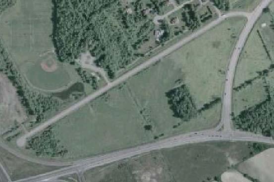
4 SLOPE STABILITY ASSESSMENT 4401 FALLOWFIELD ROAD LANDS 2.0 DESCRIPTION OF PROJECT AND SITE Plans are being prepared for a proposed development to be located at 4401 Fallowfield Road in Ottawa, Ontario (see Key Plan, Figure 1). The overall property is irregular in shape and measures approximately 800 metres by 250 metres in plan area. The site is currently undeveloped and contains variable amounts of tree and brush coverage. The site is bounded to the north by O Keefe Court, to the east by Fallowfield Road, to the south by Strandherd Drive, and to the west by the Highway 416 northbound on-ramp. The property is crossed by a shallow creek which flows across the site in a north-south direction in an approximately 2 to 3 metre deep valley. Fill material has been placed adjacent to the creek slopes. The stability of the creek slopes needs to be evaluated so that the extent of potential Hazard Lands (which are generally un-developable) can be identified. Kollard Associates (Kollard) has carried out two subsurface investigations on this site which included 20 test pits and 2 boreholes. The results of those two previous investigations are provided in the following reports: Additional Subsurface Investigation, Proposed Residential and Commercial Development, O Keefe Court and Fallowfield Road, Ottawa, Ontario dated March 5, 2008 (project number ). Preliminary Subsurface Investigation, Proposed Residential and Commercial Development, O Keefe Court and Fallowfield Road, Ottawa, Ontario dated August 2006 (project number ). Based on the results of those two previous investigations, as well as a review of published geology mapping, the subsurface conditions on this site are indicated to consist of fill and silty clay over glacial till and bedrock. Publish trends in drift thickness (i.e., thickness of soil cover over the bedrock) mapping indicates that the depth to the bedrock surface is about 1 metre (on the west side of the site) to about 10 metres (on the east side of the site). Bedrock geology mapping indicates the bedrock to consist of limestone and dolomite of the Gull River Formation on the west side of the site and sandstone and dolomite of the March Formation on the east side of the site. August 2014 Report No Rev-02 2
5 SLOPE STABILITY ASSESSMENT 4401 FALLOWFIELD ROAD LANDS 3.0 SITE RECONNAISSANCE A reconnaissance of the site was carried out on February 4, The purpose of the site reconnaissance was to view the site condition, to measure the slope geometry, and to observe the state of erosion at the toes of the slopes. A second site reconnaissance was carried out on April 11, 2014 to observe the site conditions and state of erosion once all of the snow cover has melted. A total of five slope cross sections (labelled S1 to S5, inclusive) were surveyed at locations along the creek. The survey was carried out using a Trimble R8 GPS survey unit. Slope angles and slope heights were also measured with a hand clinometer. The effective top of slope for both the creek and fill slopes were also surveyed along both sides of the creek. The approximate locations of the surveyed slope cross sections are shown on the Site Plan, Figure 2. The surveyed tops of slopes are also shown on Figure 2. August 2014 Report No Rev-02 3
6 SLOPE STABILITY ASSESSMENT 4401 FALLOWFIELD ROAD LANDS 4.0 SUBSURFACE CONDITIONS 4.1 General The subsurface conditions encountered in the boreholes put down for the previous investigation are shown on the Record of Boreholes in Appendix A. The subsurface conditions encountered in the test pits put down across the site for the previous investigation are shown on the Record of Test Pits (Table 1) in Appendix A. In general, the subsurface conditions in the area of the creek consist of up to about 2.7 metres of fill over about 2 metres of silty clay over glacial till. The following sections present a more detailed overview of the subsurface conditions encountered in borehole 1 and test pits 11 to 13, inclusive, which were advanced within close proximity of the creek. 4.2 Fill and Topsoil Fill was encountered at the ground surface at the borehole and test pit locations. The fill consists of topsoil, clay, gravel, and boulders with variable amounts of asphaltic concrete, wood, and brick. The fill extends to depths of about 1.8 to 2.7 metres below the ground surface. A buried layer of topsoil was encountered beneath the fill at the testhole locations. The topsoil varied from about 100 to 300 millimetres in thickness. 4.3 Silty Clay The fill and topsoil are underlain by a deposit of silty clay. In test pits 11 and 13, the silty clay to the depth investigated (3.6 and 3.5 metres, respectively) has been weathered to a very stiff grey brown crust. The weathered crust extends to about 4 metres depth in borehole 1. The weathered silty clay was absent in test pit 12. The silty clay below the depth of weathering is grey in colour. The unweathered silty clay was not fully penetrated in test pit 12 but was proven to a depth of about 3.8 metres below the ground surface prior to the test pit being terminated. The unweathered silty clay was fully penetrated in borehole 1, where this deposit extends to a depth of about 5 metres below the ground surface. One standard penetration test carried out within the unweathered silty clay gave an N value of 7 blows per 0.3 metres of penetration. The result of one in-situ vane test in this material gave an undrained shear strength of 52 kilopascals. The results of the in situ testing indicate the unweathered silty clay to have a stiff to very stiff consistency. 4.4 Glacial Till A deposit of glacial till was encountered beneath the silty clay in borehole 1. The glacial till consists of silty sand with some gravel, cobbles, and boulders with a trace of clay. The glacial till was proven to extend to a depth of about 5.5 metres below the ground surface prior to the borehole encountering practical refusal to augering. One standard penetration test N value for this material of greater than 50 blows per 0.3 metres of penetration indicate a very dense state of compactness. It should however be noted that this high N value may reflect the presence of cobbles and boulders within the glacial till, and not the state of compactness of the soil matrix. August 2014 Report No Rev-02 4
7 SLOPE STABILITY ASSESSMENT 4401 FALLOWFIELD ROAD LANDS 4.5 Auger Refusal Practical refusal to augering was encountered at borehole 1 at a depth of approximately 5.5 metres below the ground surface. Auger refusal may indicate the bedrock surface; however, it could also represent cobbles and/or boulders within the glacial till. 4.6 Groundwater The groundwater level in the standpipe in borehole 1 was measured to be at about 2.8 metres depth below the ground surface on February 17, The groundwater levels within the test pits were noted at depths of about 2.6 to 3.5 metres below the ground surface on July 7, Groundwater levels are expected to fluctuate seasonally. Higher groundwater levels are expected during wet periods of the year, such as spring. August 2014 Report No Rev-02 5
8 SLOPE STABILITY ASSESSMENT 4401 FALLOWFIELD ROAD LANDS 5.0 DISCUSSION 5.1 General This section of the report provides an assessment of the stability of the existing slope geometries and the corresponding extent of Hazard Lands. The reader is referred to the Important Information and Limitations of This Report which follows the text but forms an integral part of this document. 5.2 Slope Stability Assessment This assessment includes the evaluation of the stability of the existing slopes along the west and east sides of the creek in order to establish a horizontal limit of developable land (i.e., Limit of Hazard Lands associated with the slopes), based the geometry of the slopes at various locations Results of Slope Mapping As discussed in Section 3.0, mapping of the slopes along the creek was carried out using a Trimble R8 GPS unit and a hand clinometer. The measured cross section geometries are provided on Figures 3 to 7. In general, the slopes of the creek are about 1.5 to 2 metres in height and have a maximum inclination of about 20 to 30 degrees from horizontal. As previously discussed, up to about 2.7 metres of fill exists adjacent to the creek. The fill slopes are up to about 4.5 metres in height (i.e., extending up to about 2.5 metres above the creek slopes). At the time of the site visit on April 11, 2014, minor erosion was observed at the toes of the slopes Analysis Limit equilibrium slope stability analyses were carried out to assess the stability of the existing slopes. For this assessment, one cross section (e.g., both the east and west bank of the creek) was selected for detailed analysis, based on the highest slope and steepest inclination, with each slope considered to be the most critical of the conditions along each bank of the creek. In general, slope failures occur when the forces (or rotational moments) generated by the weight of the soil in a slope and external loads exceed the shear strength of the soil. The six main parameters involved in the engineering analysis of the stability of a slope are: 1) The geometry of the slope; 2) The subsurface stratigraphy within the slope (i.e., the composition of the various soil layers within the slope and their depth, thickness, and orientation); 3) The groundwater conditions (the groundwater levels and the hydraulic gradient/flow conditions); 4) The strength parameters for the soils; 5) The unit weights (i.e., densities) of the soils within the slope; and, 6) External loads on the slope, such as from foundations of structures, filling above the slope, or earthquakes. August 2014 Report No Rev-02 6
9 SLOPE STABILITY ASSESSMENT 4401 FALLOWFIELD ROAD LANDS For this site, the geometries of the slopes were based on the slope mapping, as described previously. The subsurface stratigraphy used in the analyses was based on borehole 1 and test pits 11 to 13, inclusive, which were put down for the previous investigations. The stratigraphy is considered to consist of a surficial layer of fill over stiff silty clay over compact glacial till. Static and seismic slope stability analyses were carried out with the commercially available SLOPE/W software (produced by Geo-Studio 2007), using the soil parameters given in the following table. Material Drained Parameters Effective Angle of Internal Friction (degrees) Effective Cohesion (kpa) Undrained Shear Strength (kpa) Unit Weight (kn/m 3 ) Fill 32 0 Note 1 19 Weathered Silty Clay Crust Grey Silty Clay Glacial Till Impenetrable Note: 1 Same parameters apply as for drained loading conditions. The groundwater conditions within the slopes for static conditions were conservatively assumed to be at the ground surface. The groundwater conditions within the slopes for seismic conditions were conservatively assumed to be at the interface between the fill and the native silty clay. The stability of the slopes was evaluated for: Drained (i.e., long-term, static) conditions, for which effective stress soil parameters were used. Seismic conditions (i.e., the dynamic loading conditions during an earthquake), for which undrained shear strength parameters were used. A horizontal seismic coefficient of 0.16 was used for the analyses. This value is based on the peak horizontal ground acceleration for Ottawa specified in the 2012 Ontario Building Code (with half that value being used, per standard practice). The stability of the slopes was evaluated using limit equilibrium methods and the SLOPE/W software. The Morgenstern-Price method was used to compute the factor of safety. The factor of safety is defined as the ratio of the magnitude of the forces/moments tending to resist failure to the magnitude of the forces/moments tending to cause failure. Theoretically, a slope with a factor of safety of less than 1.0 will fail and one with a factor of safety of 1.0 or greater will stand. However, because the modeling is not exact and natural variations exist for all of the parameters affecting slope stability, a factor of safety of 1.5 is used to define a stable slope (for static loading conditions), and/or to define the safe set-back distance from an unstable slope. For seismic loading conditions, a factor of safety of 1.1 is typically used. August 2014 Report No Rev-02 7
10 SLOPE STABILITY ASSESSMENT 4401 FALLOWFIELD ROAD LANDS Results The results of the stability analyses carried out for drained (i.e., static) conditions indicate that the factors of safety against global instability of the existing slopes are greater than 1.5, and these slopes are therefore considered stable from a geotechnical perspective. The factor of safety against instability under seismic loading was determined to be greater than 1.1 and therefore the slopes are also considered stable during an earthquake. The results of the static analyses are provided on Figure 8. The results of the seismic analyses are provided on Figure 9. Hazard Lands associated with unstable slopes, as defined by Ministry of Natural Resources (MNR) guidelines and provincial planning policies, are unsuitable for development with either publicly owned infrastructure or private development. In accordance with the MNR guidelines, the set-back distance from the crest of an unstable slope to the Limit of Hazard Lands should include three components, as appropriate, namely: 1) A Stable Slope Allowance, which is determined as the limit beyond which there is an acceptable factor of safety (i.e., greater than about 1.5 static or 1.1 seismic) against the table land being impacted by a slope failure. 2) An Erosion Allowance, to account for future movement of the slope toe, in the table land direction, as a result of erosion along the slope toe/creek bank. The magnitude of the Erosion Allowance depends upon the type of soil being eroded at the slope toe, the severity of the erosion, and the water course characteristics. 3) An Erosion Access Allowance of 6 metres, to allow a corridor by which equipment could travel to access and repair a future slope failure. This Erosion Access Allowance is included in the determination of the Limit of Hazard Lands wherever the development could restrict future slope access. Stable Slope Allowance For this site, the results of the stability analyses indicate that the factors of safety against global instability of the existing slopes for both static and seismic conditions are greater than 1.5 and 1.1, respectively, and these slopes are considered stable. This being the case, a Stable Slope Allowance is not required. Additional significant filling of the table land area could negatively impact on the stability of the adjacent creek slope and increase the required set-back. If additional significant filling is considered for this site, the stability of the slopes should be reassessed. Erosion Allowance An Erosion Allowance needs to be applied wherever there is active erosion, or the potential for active erosion based on the flow velocities. Based on the observations of the current erosion conditions, it is considered that the magnitude of the Erosion Allowance for this site, based on the MNR guidelines, would be 5 metres. However, if erosion protection were to be installed along the creek bank, then, at least for those specific sections of bank and slope where erosion protection were installed, an Erosion Allowance need not be included in the determination of the Limit of Hazard Lands. Detailed guidelines on the nature of the erosion protection are not provided in this report. However, conceptually, the erosion protection could consist of rip-rap, placed on a maximum 2 horizontal to 1 vertical front slope up to the 100 year flood level, and underlain by a non-woven geotextile. Further guidelines on erosion protection options can be provided, if required. August 2014 Report No Rev-02 8
11 SLOPE STABILITY ASSESSMENT 4401 FALLOWFIELD ROAD LANDS If erosion protection is to be considered, other studies and regulatory approvals could be required, such as with respect to environmental impacts, fish habitat, and alterations to the waterway. The feasibility of obtaining these approvals has not been evaluated. Erosion Access Allowance The Erosion Access Allowance included in the MNR procedures for determining the Limit of Hazard Lands is intended to provide a corridor of sufficient width across the table land that equipment could access the site of a future slope failure to undertake a repair. The width of the Erosion Access Allowance is typically 6 metres. The MNR documents do not provide guidance on those situations where the Erosion Access Allowance need, or not need, be applied. However, as a general guideline, the Erosion Access Allowance should be included wherever the development plans would preclude equipment access to the slope. For example, it should be included where buildings or fences will be constructed right up to the Limit of Hazard Lands. But it probably need not be included in the Limit of Hazard Lands associated with the construction of a parking lot of the table land area, since equipment could cross the parking lot. Judgement needs to be used in its application. Limit of Hazard Land Summary The following table provides a summary of the various set-back components which are applicable for determining the total set-back for this site. Stable Slope Allowance (metres) Erosion Allowance (metres) Access Allowance (metres) Total Set-Back (metres) 0 5 (1) 6 (2) 11 Notes: (1) Assumes that erosion protection will not be provided. This allowance can be reduced to 0 metres if erosion protection is provided. (2) Assumes that access to the slope is restricted. This allowance can be reduced to 0 metres if unrestricted access to the slope is available. An 11 metre set-back line has been shown on Figure 2 for both the Top of Creek Slope and Top of Fill Slope. It should be noted that the ditch slopes adjacent to the property are not as high and have a shallower inclination than the worst case creek slope (which is stable). This being the case, the slopes of the ditches (on the property side of the ditches) are considered to be stable and, as such, no additional recommendations are required for these slopes August 2014 Report No Rev-02 9
12 SLOPE STABILITY ASSESSMENT 4401 FALLOWFIELD ROAD LANDS 6.0 ADDITIONAL CONSIDERATIONS The assessment provided in this report is based on there being no significant filling on the table land area adjacent to the slope. These guidelines will therefore need to be confirmed once the site grading has been designed. August 2014 Report No Rev-02 10
13
14 IMPORTANT INFORMATION AND LIMITATIONS OF THIS REPORT Standard of Care: Golder Associates Ltd. (Golder) has prepared this report in a manner consistent with that level of care and skill ordinarily exercised by members of the engineering and science professions currently practising under similar conditions in the jurisdiction in which the services are provided, subject to the time limits and physical constraints applicable to this report. No other warranty, expressed or implied is made. Basis and Use of the Report: This report has been prepared for the specific site, design objective, development and purpose described to Golder by the Client, DCR Phoenix Homes. The factual data, interpretations and recommendations pertain to a specific project as described in this report and are not applicable to any other project or site location. Any change of site conditions, purpose, development plans or if the project is not initiated within eighteen months of the date of the report may alter the validity of the report. Golder cannot be responsible for use of this report, or portions thereof, unless Golder is requested to review and, if necessary, revise the report. The information, recommendations and opinions expressed in this report are for the sole benefit of the Client. No other party may use or rely on this report or any portion thereof without Golder's express written consent. If the report was prepared to be included for a specific permit application process, then the client may authorize the use of this report for such purpose by the regulatory agency as an Approved User for the specific and identified purpose of the applicable permit review process, provided this report is not noted to be a draft or preliminary report, and is specifically relevant to the project for which the application is being made. Any other use of this report by others is prohibited and is without responsibility to Golder. The report, all plans, data, drawings and other documents as well as all electronic media prepared by Golder are considered its professional work product and shall remain the copyright property of Golder, who authorizes only the Client and Approved Users to make copies of the report, but only in such quantities as are reasonably necessary for the use of the report by those parties. The Client and Approved Users may not give, lend, sell, or otherwise make available the report or any portion thereof to any other party without the express written permission of Golder. The Client acknowledges that electronic media is susceptible to unauthorized modification, deterioration and incompatibility and therefore the Client cannot rely upon the electronic media versions of Golder's report or other work products. The report is of a summary nature and is not intended to stand alone without reference to the instructions given to Golder by the Client, communications between Golder and the Client, and to any other reports prepared by Golder for the Client relative to the specific site described in the report. In order to properly understand the suggestions, recommendations and opinions expressed in this report, reference must be made to the whole of the report. Golder cannot be responsible for use of portions of the report without reference to the entire report. Unless otherwise stated, the suggestions, recommendations and opinions given in this report are intended only for the guidance of the Client in the design of the specific project. The extent and detail of investigations, including the number of test holes, necessary to determine all of the relevant conditions which may affect construction costs would normally be greater than has been carried out for design purposes. Contractors bidding on, or undertaking the work, should rely on their own investigations, as well as their own interpretations of the factual data presented in the report, as to how subsurface conditions may affect their work, including but not limited to proposed construction techniques, schedule, safety and equipment capabilities. Soil, Rock and Groundwater Conditions: Classification and identification of soils, rocks, and geologic units have been based on commonly accepted methods employed in the practice of geotechnical engineering and related disciplines. Classification and identification of the type and condition of these materials or units involves judgment, and boundaries between different soil, rock or geologic types or units may be transitional rather than abrupt. Accordingly, Golder does not warrant or guarantee the exactness of the descriptions. Golder Associates Ltd. Page 1 of 2
15 IMPORTANT INFORMATION AND LIMITATIONS OF THIS REPORT (cont'd) Special risks occur whenever engineering or related disciplines are applied to identify subsurface conditions and even a comprehensive investigation, sampling and testing program may fail to detect all or certain subsurface conditions. The environmental, geologic, geotechnical, geochemical and hydrogeologic conditions that Golder interprets to exist between and beyond sampling points may differ from those that actually exist. In addition to soil variability, fill of variable physical and chemical composition can be present over portions of the site or on adjacent properties. The professional services retained for this project include only the geotechnical aspects of the subsurface conditions at the site, unless otherwise specifically stated and identified in the report. The presence or implication(s) of possible surface and/or subsurface contamination resulting from previous activities or uses of the site and/or resulting from the introduction onto the site of materials from off-site sources are outside the terms of reference for this project and have not been investigated or addressed. Soil and groundwater conditions shown in the factual data and described in the report are the observed conditions at the time of their determination or measurement. Unless otherwise noted, those conditions form the basis of the recommendations in the report. Groundwater conditions may vary between and beyond reported locations and can be affected by annual, seasonal and meteorological conditions. The condition of the soil, rock and groundwater may be significantly altered by construction activities (traffic, excavation, groundwater level lowering, pile driving, blasting, etc.) on the site or on adjacent sites. Excavation may expose the soils to changes due to wetting, drying or frost. Unless otherwise indicated the soil must be protected from these changes during construction. Sample Disposal: Golder will dispose of all uncontaminated soil and/or rock samples 90 days following issue of this report or, upon written request of the Client, will store uncontaminated samples and materials at the Client's expense. In the event that actual contaminated soils, fills or groundwater are encountered or are inferred to be present, all contaminated samples shall remain the property and responsibility of the Client for proper disposal. Follow-Up and Construction Services: All details of the design were not known at the time of submission of Golder's report. Golder should be retained to review the final design, project plans and documents prior to construction, to confirm that they are consistent with the intent of Golder's report. During construction, Golder should be retained to perform sufficient and timely observations of encountered conditions to confirm and document that the subsurface conditions do not materially differ from those interpreted conditions considered in the preparation of Golder's report and to confirm and document that construction activities do not adversely affect the suggestions, recommendations and opinions contained in Golder's report. Adequate field review, observation and testing during construction are necessary for Golder to be able to provide letters of assurance, in accordance with the requirements of many regulatory authorities. In cases where this recommendation is not followed, Golder's responsibility is limited to interpreting accurately the information encountered at the borehole locations, at the time of their initial determination or measurement during the preparation of the Report. Changed Conditions and Drainage: Where conditions encountered at the site differ significantly from those anticipated in this report, either due to natural variability of subsurface conditions or construction activities, it is a condition of this report that Golder be notified of any changes and be provided with an opportunity to review or revise the recommendations within this report. Recognition of changed soil and rock conditions requires experience and it is recommended that Golder be employed to visit the site with sufficient frequency to detect if conditions have changed significantly. Drainage of subsurface water is commonly required either for temporary or permanent installations for the project. Improper design or construction of drainage or dewatering can have serious consequences. Golder takes no responsibility for the effects of drainage unless specifically involved in the detailed design and construction monitoring of the system. Golder Associates Ltd. Page 2 of 2

16 Path: \\golder.gds\gal\ottawa\active\2014\ ES&A\ Okeefe Court DCR_Pheonix\Spatial IM\CAD\PRODUCTION\Phase 4000\ File Name: dwg NOTES 1. THIS FIGURE IS TO BE READ IN CONJUNCTION WITH THE ACCOMPANYING GOLDER ASSOCIATES LTD. REPORT No CLIENT DCR PHOENIX HOMES CONSULTANT YYYY-MM-DD PREPARED DESIGN REVIEW APPROVED JM WAM TMS TMS PROJECT SLOPE STABILITY ASSESSMENT PROPOSED DEVELOPMENT 4401 FALLOWFIELD ROAD LANDS, OTTAWA, ONTARIO TITLE KEY PLAN PROJECT No : PHASE Rev. A METRES FIGURE 1 IF THIS MEASUREMENT DOES NOT MATCH WHAT IS SHOWN, THE SHEET SIZE HAS BEEN MODIFIED FROM: ANSI A 0 25 mm
17 LEGEND S1 APPROXIMATE CROSS-SECTION LOCATION IN PLAN LIMIT OF HAZARD LANDS BASED ON TOP OF FILL SLOPE (EROSION AND ACCESS ALLOWANCE) LIMIT OF HAZARD LANDS BASED ON TOP OF FILL SLOPE (EROSION ALLOWANCE) LIMIT OF HAZARD LANDS BASED ON TOP OF CREEK SLOPE (EROSION AND ACCESS ALLOWANCE) LIMIT OF HAZARD LANDS BASED ON TOP OF CREEK SLOPE (EROSION ALLOWANCE) NOTES 1. THIS FIGURE IS TO BE READ IN CONJUNCTION WITH THE ACCOMPANYING GOLDER ASSOCIATES LTD. REPORT No REFERENCE BASE PLAN SUPPLIED IN ELECTRONIC FORMAT BY MMM Path: \\golder.gds\gal\ottawa\active\2014\ ES&A\ Okeefe Court DCR_Pheonix\Spatial IM\CAD\PRODUCTION\Phase 4000\ File Name: dwg CLIENT DCR PHOENIX HOMES PROJECT SLOPE STABILITY ASSESSMENT PROPOSED DEVELOPMENT 4401 FALLOWFIELD ROAD LANDS, OTTAWA, ONTARIO TITLE SITE PLAN CONSULTANT PROJECT No :2,500 PHASE YYYY-MM-DD PREPARED DESIGN REVIEW APPROVED METRES Rev. A JM WAM TMS TMS FIGURE 2 IF THIS MEASUREMENT DOES NOT MATCH WHAT IS SHOWN, THE SHEET SIZE HAS BEEN MODIFIED FROM: ANSI B 0 25 mm
18 Elevation (m) Cross Section S West East Distance (m) Slope Stability Cross Section Proposed Development 4401 Fallowfield Road, Ottawa Project No Drawn: WAM Date: 2/12/2014 Checked: TMS Review: TMS Figure 3
19 Elevation (m) Cross Section S West East Distance (m) Slope Stability Cross Section Proposed Development 4401 Fallowfield Road, Ottawa Project No Drawn: WAM Date: 2/12/2014 Checked: TMS Review: TMS Figure 4
20 Elevation (m) Cross Section S West East Distance (m) Slope Stability Cross Section Proposed Development 4401 Fallowfield Road, Ottawa Project No Drawn: WAM Date: 2/12/2014 Checked: TMS Review: TMS Figure 5
21 Elevation (m) Cross Section S West East Distance (m) Slope Stability Cross Section Proposed Development 4401 Fallowfield Road, Ottawa Project No Drawn: WAM Date: 2/12/2014 Checked: TMS Review: TMS Figure 6
22 Elevation (m) Cross Section S West East Distance (m) Slope Stability Cross Section Proposed Development 4401 Fallowfield Road, Ottawa Project No Drawn: WAM Date: 2/12/2014 Checked: TMS Review: TMS Figure 7

23 Static Assessment Project No Drawn: WAM Date: 2/12/2014 Checked: TMS Review: TMS Figure 8

24 Seismic Assessment Project No Drawn: WAM Date: 2/12/2014 Checked: TMS Review: TMS Figure 9
25 SLOPE STABILITY ASSESSMENT 4401 FALLOWFIELD ROAD LANDS APPENDIX A Record of Boreholes from Previous Investigation by Kollard Record of Test Pits from Previous Investigation by Kollard Figure 1 from Previous Investigation by Kollard August 2014 Report No Rev-02
26
27
28
29
30
31
32
33
34
35

36 Golder Associates Ltd. 32 Steacie Drive Kanata, Ontario, K2K 2A9 Canada T: +1 (613)
patersongroup Consulting Engineers April 20, 2010 File: PG1887-LET.01R Novatech Engineering Consultants Suite 200, 240 Michael Cowpland Drive
 patersongroup April 20, 2010 File: PG1887-LET.01R Novatech Engineering Consultants Suite 200, 240 Michael Cowpland Drive Ottawa, Ontario K2M 1P6 Attention: Mr. Adam Thompson Consulting Engineers 28 Concourse
June 9, R. D. Cook, P.Eng. Soils Engineer Special Services Western Region PUBLIC WORKS CANADA WESTERN REGION REPORT ON
 PUBLIC WORKS CANADA WESTERN REGION REPORT ON GEOTECHNICAL INVESTIGATION PROPOSED MARTIN RIVER BRIDGE MILE 306.7 MACKENZIE HIGHWAY Submitted by : R. D. Cook, P.Eng. Soils Engineer Special Services Western
patersongroup Mineral Aggregate Assessment 3119 Carp Road Ottawa, Ontario Prepared For Mr. Greg LeBlanc March 7, 2014 Report: PH2223-REP.
 Geotechnical Engineering Environmental Engineering group Hydrogeology Geological Engineering Archaeological Studies Materials Testing 3119 Carp Road Prepared For Mr. Greg LeBlanc March 7, 2014 Paterson
General. DATE December 10, 2013 PROJECT No TO Mary Jarvis Urbandale/Riverside South Development Corporation
 DATE December 10, 201 PROJECT No. 10-1121-0260- TO Mary Jarvis Urbandale/Riverside South Development Corporation CC Justin Robitaille, Urbandale Jonathan Párraga, J.L. Richards & Associates Limited FROM
Central Queensland Coal Project Appendix 4b Geotechnical Assessment. Environmental Impact Statement
 Central Queensland Coal Project Appendix 4b Geotechnical Assessment Environmental Impact Statement GEOTECHNICAL ASSESSMENT OF OPEN CUT MINING ADJACENT TO THE BRUCE HIGHWAY, CENTRAL QUEENSLAND COAL PROJECT
REPORT ON SLOPE STABILITY INVESTIGATION DON MILLS ROAD AND EGLINTON AVENUE EAST TORONTO, ONTARIO. Prepared for:
 REPORT ON SLOPE STABILITY INVESTIGATION DON MILLS ROAD AND EGLINTON AVENUE EAST TORONTO, ONTARIO Prepared for: TORONTO AND REGION CONSERVATION AUTHORITY Prepared By: SIRATI & PARTNERS CONSULTANTS LIMITED
1.0 INTRODUCTION 2.0 OBSERVATIONS EBA FILE: W nd Avenue Whitehorse, YT Y1A 1C2. Attention:
 August 5, 2013 City of Whitehorse 2121 2 nd Avenue Whitehorse, YT Y1A 1C2 ISSUED FOR USE EBA FILE: W14103182-01 Via Email: ben.campbell@whitehorse.ca Attention: Subject: Ben Campbell, Planner II Planning
Pierce County Department of Planning and Land Services Development Engineering Section
 Page 1 of 7 Pierce County Department of Planning and Land Services Development Engineering Section PROJECT NAME: DATE: APPLICATION NO.: PCDE NO.: LANDSLIDE HAZARD AREA (LHA) GEOLOGICAL ASSESSMENT REPORT
Hydrogeological Assessment for Part of Lots 2 and 3, Concession 5, Township of Thurlow, County of Hastings 1.0 INTRODUCTION. 1.
 February 10,2017 25506400 Ontario Ltd. Foxboro, ON Attention: Brad Newbatt Re: Hydrogeological Assessment for Part of Lots 2 and 3, Concession 5, Township of Thurlow, County of Hastings 1.0 INTRODUCTION
August 10, 2007 File:
 August 10, 2007 File: 15-85-72 Alberta Infrastructure and Transportation Room 301, Provincial Building 9621-96 Avenue Peace River, AB T8S 1T4 Attention: Mr. Ed Szmata PEACE REGION (PEACE HIGH LEVEL AREA)
SLOPE STABILITY EVALUATION AND ACCEPTANCE STANDARDS
 INFORMATION BULLETIN / PUBLIC - BUILDING CODE REFERENCE NO.: LAMC 98.0508 Effective: 1-26-84 DOCUMENT NO. P/BC 2002-049 Revised: 11-1-02 Previously Issued As: RGA #1-84 SLOPE STABILITY EVALUATION AND ACCEPTANCE
GEOTECHNICAL REPORT CBSA Facility Redevelopment Thousand Islands International Crossing Lansdowne, Ontario
 GEOTECHNICAL REPORT CBSA Facility Redevelopment Thousand Islands International Crossing Lansdowne, Ontario Prepared For: The Federal Bridge Corporation Limited SPL Project No.: 10001084 Report Date: January
Converse Consultants Geotechnical Engineering, Environmental & Groundwater Science, Inspection & Testing Services
 Converse Consultants Geotechnical Engineering, Environmental & Groundwater Science, Inspection & Testing Services Ms. Rebecca Mitchell Mt. San Antonio College Facilities Planning & Management 1100 North
This report was prepared by Klohn Crippen Consultants Ltd. for Alberta Transportation Central Region under Contract No. CE053/2000.
 Alberta Transportation Central Region #401, 4902 51 Street Red Deer, Alberta T4N 6K8 June 7, 2002 Mr. Melvin Mayfield, P.Eng. Project Engineer Dear Mr. Mayfield: Central Region Landslide Assessment Site
CENTRAL REGION GEOHAZARDS RISK ASSESSMENT SITE INSPECTION FORM
 SITE NUMBER AND NAME C55 H861:02 Slide LEGAL DESCRIPTION NW 14-40-14-W4 CENTRAL REGION GEOHAZARDS RISK ASSESSMENT SITE INSPECTION FORM HIGHWAY & KM NAD 83 COORDINATES N 5811217 E 437291 PREVIOUS INSPECTION
Preliminary Geotechnical Evaluation Gooseberry Point Pedestrian Improvements Whatcom County, Washington SITE AND PROJECT DESCRIPTION
 File No. 12-100 Geotechnical & Earthquake Engineering Consultants Mr. Kevin Brown, P.E. Gray & Osborne, Inc. 3710 168 th Street NE, Suite B210 Arlington, Washington 98223 Subject: Draft Report Preliminary
Date: April 2, 2014 Project No.: Prepared For: Mr. Adam Kates CLASSIC COMMUNITIES 1068 E. Meadow Circle Palo Alto, California 94303
 City of Newark - 36120 Ruschin Drive Project Draft Initial Study/Mitigated Negative Declaration Appendix C: Geologic Information FirstCarbon Solutions H:\Client (PN-JN)\4554\45540001\ISMND\45540001 36120
Submitted to: Taggart Realty Management 225 Metcalfe Street, Suite 708 Ottawa, Ontario K2P 1P9
 REPORT ON Preliminary Geotechnical Assessment Proposed Development Hunt Club Road and Riverside Drive Ottawa, Ontario Submitted to: Taggart Realty Management 225 Metcalfe Street, Suite 708 Ottawa, Ontario
IAEA SAFETY STANDARDS Geotechnical Aspects of Site Evaluation and Foundations in NPPs, NS-G-3.6
 IAEA SAFETY STANDARDS Geotechnical Aspects of Site Evaluation and Foundations in NPPs, NS-G-3.6 Regional Workshop on Volcanic, Seismic, and Tsunami Hazard Assessment Related to NPP Siting Activities and
Appendix A. Producer Statement Advisory Note
 Appendix A Producer Statement Advisory Note Ref. No. 17095 26 May 2017 PRODUCER STATEMENT CONSTRUCTION REVIEW (PS4) IMPORTANT ADVISORY NOTE The Building Consent Authority (BCA) frequently requires Producer
CHAPTER GEOLOGICALLY HAZARDOUS AREAS Applicability Regulations.
 CHAPTER 19.07 GEOLOGICALLY HAZARDOUS AREAS 19.07.010 Applicability. Geologically hazardous areas may pose a threat to the health and safety of citizens when incompatible development is sited in areas of
SLOPE STABILITY ASSESSMENT PROPOSED RESIDENTIAL SUBDIVISION 161 LAKESHORE ROAD EAST TOWN OF THE BLUE MOUNTAINS, ONTARIO
 SLOPE STABILITY ASSESSMENT PROPOSED RESIDENTIAL SUBDIVISION 161 LAKESHORE ROAD EAST TOWN OF THE BLUE MOUNTAINS, ONTARIO PETO MacCALLUM LTD. 19 CHURCHILL DRIVE BARRIE, ONTARIO L4N 8Z5 PHONE: (705) 734-3900
ROCK EXCAVATION (GRADING) OPSS 206 INDEX
 OPSS 206 INDEX") 206-2 - OPSS 206 INDEX 206-2.1 GENERAL 206-2.1.1 Classification of Rock Materials 206-2.1.2 Tender Items 206-2.1.3 Other Excavation Tender Items 206-2.1.4 Specifications 206-2.1.5 Special Provisions 206-2.1.6
206-2 - OPSS 206 INDEX 206-2.1 GENERAL 206-2.1.1 Classification of Rock Materials 206-2.1.2 Tender Items 206-2.1.3 Other Excavation Tender Items 206-2.1.4 Specifications 206-2.1.5 Special Provisions 206-2.1.6
APPENDIX H SOIL SURVEY
 Environmental Impact Statement Beryl Solar Farm APPENDIX H SOIL SURVEY Beryl Solar Farm 16 347 Final V1 H i Geotechnical Engineers & Engineering Geologists NATA Accredited Laboratories for Asphalt, Aggregate,
ATTACHMENT A PRELIMINARY GEOTECHNICAL SUMMARY
 ATTACHMENT A PRELIMINARY GEOTECHNICAL SUMMARY Kevin M. Martin, P.E. KMM Geotechnical Consultants, LLC 7 Marshall Road Hampstead, NH 0384 603-489-6 (p)/ 603-489-8 (f)/78-78-4084(m) kevinmartinpe@aol.com
September 18, 2017 Project No.: 5077
 #109 3011 Underhill Avenue Burnaby, BC V5A 3C2 Phone: (604) 421-3288 Email: info@terrangeo.com September 18, 2017 Project No.: 5077 Kevin Brooks City of Campbell River 301 St. Ann s Road Campbell River,
Materials. Use materials meeting the following.
 208.01 Section 208. SOIL EROSION AND SEDIMENTATION CONTROL 208.01 Description. Install and maintain erosion and sedimentation controls to minimize soil erosion and to control sedimentation from affecting
16 January 2018 Job Number: RICHARD NEWMAN C\- CLARK FORTUNE MCDONALD AND ASSOCIATES PO BOX 553 QUEENSTOWN
 16 January 2018 Job Number: 50595 RICHARD NEWMAN C\- CLARK FORTUNE MCDONALD AND ASSOCIATES PO BOX 553 QUEENSTOWN CHANSEN@CFMA.CO.NZ STORMWATER DISPOSAL ASSESSMENT Dear Richard, RDAgritech were requested
TECHNICAL SUPPORT DOCUMENT # 1 COMPARATIVE EVALUATION OF ALTERNATIVE SITES APPENDIX TSD#1-H. Design & Operations Component
 TECHNICAL SUPPORT DOCUMENT # 1 COMPARATIVE EVALUATION OF ALTERNATIVE SITES APPENDIX TSD#1-H Design & Operations Component February 2013 February 2013 Design & Operations Component Appendix TSD#1-H COMPARATIVE
Updated Subsurface Investigation Block A Heritage Hills Development 124 Battersea Crescent Ottawa, Ontario
 Updated Subsurface Investigation Block A Heritage Hills Development 124 Battersea Crescent Ottawa, Ontario Submitted to: Brigil Homes 98 rue Lois Gatineau, Quebec J8Y 3R7 Updated Subsurface Investigation
SOIL INVESTIGATION REPORT. PROPOSED HOUSING DEVELOPMENT PROJECT Coral Spring, Trelawny, Jamaica.
 SOIL INVESTIGATION REPORT PROPOSED HOUSING DEVELOPMENT PROJECT Coral Spring, Trelawny, Jamaica. Prepared for: FCS Consultants 7a Barbados Avenue Kingston 5, Jamaica Prepared by: NHL Engineering Limited
Slope Stability Evaluation Ground Anchor Construction Area White Point Landslide San Pedro District Los Angeles, California.
 Slope Stability Evaluation Ground Anchor Construction Area White Point Landslide San Pedro District Los Angeles, California Submitted To: Mr. Gene Edwards City of Los Angeles Department of Public Works
SLOPE STABILITY EVALUATION AND ACCEPTANCE STANDARDS
 INFORMATION BULLETIN / PUBLIC - BUILDING CODE REFERENCE NO.: LABC 7006.3, 7014.1 Effective: 01-01-2017 DOCUMENT NO.: P/BC 2017-049 Revised: 12-21-2016 Previously Issued As: P/BC 2014-049 SLOPE STABILITY
How & Where does infiltration work? Summary of Geologic History Constraints/benefits for different geologic units
 June 26, 2007: Low Impact Development 1 Associated Earth Sciences, Inc. Associated Earth Sciences, Inc. Presented by: Matthew A. Miller, PE April 24, 2012 How & Where does infiltration work? Summary of
1 PROJECT BACKGROUND. August 14, Alberta Transportation Central Region #401, Street Red Deer, Alberta T4N 6K8
 August 14, 2013 Alberta Transportation Central Region #401, 4902 51 Street Red Deer, Alberta T4N 6K8 Mr. Dennis Grace, P.Eng. Construction Engineer Dear Mr. Grace: Central Region Geohazard Assessment 2013
1. PROJECT BACKGROUND. July 18, Alberta Infrastructure & Transportation Central Region #401, Street Red Deer, Alberta T4N 6K8
 July 18, 2005 Alberta Infrastructure & Transportation Central Region #401, 4902 51 Street Red Deer, Alberta T4N 6K8 Mr. Alain Momedi, P.Eng. Project Engineer Dear Mr. Momedi: H11:04 km 11.1 Erosion along
3.12 Geology and Topography Affected Environment
 3 Affected Environment and Environmental Consequences 3.12 Geology and Topography 3.12.1 Affected Environment 3.12.1.1 Earthquakes Sterling Highway MP 45 60 Project Draft SEIS The Kenai Peninsula is predisposed
Landslide FE Stability Analysis
 Landslide FE Stability Analysis L. Kellezi Dept. of Geotechnical Engineering, GEO-Danish Geotechnical Institute, Denmark S. Allkja Altea & Geostudio 2000, Albania P. B. Hansen Dept. of Geotechnical Engineering,
PAVEMENT REPORT. Submitted to: Lee Jablonski, P.Eng. J.L. Richards & Associates Limited 864 Lady Ellen Place Ottawa, ON K1Z 5M2
 PAVEMENT REPORT GEOTECHNICAL INVESTIGATION FOR THE REHABILITATION OF LOUIS HEBERT STREET, VAUDREUIL STREET, MARQUELLE STREET AND LASALLE STREET, ROCKLAND, ONTARIO Submitted to: Lee Jablonski, P.Eng. J.L.
The results of KCB s site inspection observations and our recommendations for further work are presented herein.
 July 14, 2015 Central Region 401, 4902 51 Street Red Deer, Alberta T4N 6K8 Mr. Tony Penney, P.Eng. Construction Engineer Dear Mr. Penney: June 25, 2015 Site Inspection Report The above site was visited
MAPPING BEDROCK: Verifying Depth to Bedrock in Calumet County using Seismic Refraction
 MAPPING BEDROCK: Verifying Depth to Bedrock in Calumet County using Seismic Refraction Revised December 13, 2011 Dave Hart Wisconsin Geological and Natural History Survey INTRODUCTION Seismic refraction
WITNESS STATEMENT DANIEL MAN, P.ENG.
 WITNESS STATEMENT OF DANIEL MAN, P.ENG. Soil Engineers Ltd. 100 Nugget Avenue Toronto, Ontario M1S 3A7 Tel: (416) 754-8515 / Fax: (416) 754-8516 Email: danielman@soilengineersltd.com In the matter of Proposed
Groundwater Investigation SOUTHGATE GRAVEL PIT Part of Lot 15, Concession 15 (formerly Township of Proton), Township of Southgate.
, Township of Southgate.") Groundwater Investigation SOUTHGATE GRAVEL PIT Part of Lot 15, Concession 15 (formerly Township of Proton), Township of Southgate County of Grey October, 2014 Prepared for: Drysdale Aggregate Consulting
Groundwater Investigation SOUTHGATE GRAVEL PIT Part of Lot 15, Concession 15 (formerly Township of Proton), Township of Southgate County of Grey October, 2014 Prepared for: Drysdale Aggregate Consulting
EXHIBIT H LOT 317 GRADING AND SITE PLAN
 EXHIBIT H LOT 317 GRADING AND SITE PLAN EXHIBIT I LOT 317 ELEVATIONS ridge height 4915'-6" GENERAL & KEYED NOTES ridge height 4905'-9" 3 7 4 A5.1 1 5 ridge height 4910'-6" 2 ridge height 4906'-3" 1 Provide
GEOTECHNICAL ENGINEERING II. Subject Code : 06CV64 Internal Assessment Marks : 25 PART A UNIT 1
 GEOTECHNICAL ENGINEERING II Subject Code : 06CV64 Internal Assessment Marks : 25 PART A UNIT 1 1. SUBSURFACE EXPLORATION 1.1 Importance, Exploration Program 1.2 Methods of exploration, Boring, Sounding
patersongroup memorandum 1.0 Field Investigation consulting engineers
 consulting engineers memorandum to: KDSA Development Corporation - Ms. Susan Anglin - susananglin6@gmail.com re: Pavement Structure Recommendations - Shady Maple Road Proposed Braeburn Estates Residential
GEOTECHNICAL INVESTIGATION. Proposed Douglas Street Bus Lane
 May, 0 GEOTECHNICAL INVESTIGATION Proposed Douglas Street Bus Lane Submitted to: Greg Smith P.Eng. Senior Transportation Engineer Urban Systems Ltd. 0- Homer Street Vancouver, BC V6B W9 REPORT Report Number:
Geotechnical Investigation Proposed Retirement Residence Goulbourn Forced Road Ottawa, Ontario
 REPORT February 205 REPORT ON Geotechnical Investigation Proposed Retirement Residence Goulbourn Forced Road Ottawa, Ontario Submitted to: Dan Roach, AIA Hawthorne Development LLC c/o Lenity Architecture
Internal C Unit Dilatanc y
 2 Grimsby Sub was not at any time definitively established. The preliminary analysis provided by Thurber Engineering Ltd indicates the slope should be stable with a factor of safety of 1.23 for a deep
Geology, Soils, and Seismicity
 Section 3.8 Geology, Soils, and Seismicity Introduction This section generally evaluates the effects of the alternatives analyzed in this Supplemental DEIS with regard to geology, soils and seismicity.
REPORT ON LEVEL 1 EARTHWORKS INSPECTION AND TESTING
 29 February 2016 Project No. SGS/16/005 REPORT ON LEVEL 1 EARTHWORKS INSPECTION AND TESTING PROJECT: DEVELOPER: DILGP ECONOMIC DEVELOPMENT QLD SUPERINTENDENT: CALIBRE CONSULTING (QLD) PTY LTD CONTRACTOR:
Appendix H. Geotechnical Investigation Report. Krosno Creek Flood Reduction Project PROJECT FILE REPORT CITY OF PICKERING
 Krosno Creek Flood Reduction Project PROJECT FILE REPORT CITY OF PICKERING Appendix H Geotechnical Investigation Report TMIG THE MUNICIPAL INFRASTRUCTURE GROUP LTD Report on Geotechnical Investigation
R.M.HARW & ASSOCIATES LTD. GEOTECHNICAL INVESTIGATION PROPOSED BRIDGE SITE. HELAVA CREEKl MILE MACKENZIE HIGHWAY E-2510 OCTOBER 16, 1973
 El R.M.HARW & ASSOCIATES LTD. GEOTECHNICAL INVESTIGATION PROPOSED BRIDGE SITE HELAVA CREEKl MILE 616.4 MACKENZIE HIGHWAY E-2510 OCTOBER 16, 1973 R,M,HARDV & ASSOCIATES LTD. CONSULTING ENGINEERING & TESTING
10. GEOTECHNICAL EXPLORATION PROGRAM
 Geotechnical site investigations should be conducted in multiple phases to obtain data for use during the planning and design of the tunnel system. Geotechnical investigations typically are performed in
Geotechnical Investigation
 Geotechnical Investigation Slope Stability Analysis for the Existing Slope Southwest of the Proposed Condo Developments 50 Ann Street, Bolton, Ontario Prepared For: Brookfield Homes (Ontario) Limited GeoPro
Milford Centre Ltd. Private Plan Change GEOTECHNICAL ASSESSMENT
 Milford Centre Ltd. Private Plan Change GEOTECHNICAL ASSESSMENT Final 15 April 2008 Milford Centre Ltd. Private Plan Change GEOTECHNICAL ASSESSMENT Final 15 April 2008 Sinclair Knight Merz 25 Teed Street
Geotechnical Investigation Proposed Retirement Residence Timberwalk Ottawa, Ontario
 September 6 REPORT ON Geotechnical Investigation Proposed Retirement Residence Timberwalk Ottawa, Ontario Submitted to: Claridge Homes Corporation - Gladstone Avenue Ottawa, ON KP Y6 REPORT Report Number:
January 17, 2008 File:
 January 17, 2008 File: 15-85-73 Alberta Infrastructure and Transportation Room 301, Provincial Building 9621-96 Avenue Peace River, Alberta T8S 1T4 Attention: Mr. Ed Szmata PEACE REGION (SWAN HILLS AREA)
3.18 GEOLOGY AND SOILS
 3.18 GEOLOGY AND SOILS This section discusses geologic resource concerns as they relate to the environment, public safety, and project design both during construction and after completion of the project.
Omaroro Lower Playing Field - Geotechnical Interpretive Report
 Report Omaroro Lower Playing Field - Geotechnical Interpretive Report Prepared for Wellington Water Limited Prepared by Beca Limited 1 December 2017 Omaroro Lower Playing Field - Geotechnical Interpretive
File: Highway 1 Admirals/McKenzie Interchange, Saanich, BC Pavement Drilling / Coring Geotechnical Investigation
 TECHNICAL MEMO To: Mr. Salem Bahamdun, P.Eng. Date: February 2, 2017 c: Memo No.: From: Ms. Susanne Ouellet, E.I.T. Mr. Andrew Walker, P.Eng. File: 704TRN.PAVE0303807 ISSUED FOR USE Subject: Highway 1
Rock & Aggregate Drop Inlet Protection
 Rock & Aggregate Drop Inlet Protection SEDIMENT CONTROL TECHNIQUE Type 1 System Sheet Flow Sandy Soils Type 2 System [1] Concentrated Flow Clayey Soils Type 3 System Supplementary Trap Dispersive Soils
FOR PROJECTS INITIATED AFTER NOVEMBER 1, 2008 ITEM 716 EMBANKMENT EARTH OUTLET SEDIMENT TRAP
 AFTER NOVEMBER 1, 2008 ITEM 716 EMBANKMENT EARTH OUTLET SEDIMENT TRAP 716.1 Description. This work shall consist of furnishing, installing, maintaining, and removing temporary erosion protection and sediment
ENCE 3610 Soil Mechanics. Site Exploration and Characterisation Field Exploration Methods
 ENCE 3610 Soil Mechanics Site Exploration and Characterisation Field Exploration Methods Geotechnical Involvement in Project Phases Planning Design Alternatives Preparation of Detailed Plans Final Design
GEOLOGY, SOILS, AND SEISMICITY
 4.9 GEOLOGY, SOILS, AND SEISMICITY 4.9.1 Introduction Information about the geological conditions and seismic hazards in the study area was summarized in the FEIR, and was based on the Geotechnical Exploration
DATA REPORT GEOTECHNICAL INVESTIGATION GALVESTON CRUISE TERMINAL 2 GALVESTON, TEXAS
 DATA REPORT GEOTECHNICAL INVESTIGATION GALVESTON CRUISE TERMINAL 2 GALVESTON, TEXAS SUBMITTED TO PORT OF GALVESTON 123 ROSENBERG AVENUE, 8TH FLOOR GALVESTON, TEXAS 77553 BY HVJ ASSOCIATES, INC. HOUSTON,
December 11, 2006 File:
 December 11, 2006 File: 15-85-38 Alberta Infrastructure and Transportation Room 301, Provincial Building 9621-96 Avenue Peace River, Alberta T8S 1T4 Attention: Mr. Ed Szmata PEACE REGION (SWAN HILLS AREA)
February 18, 2003 File: NORTH CENTRAL REGION LANDSLIDE ASSESSMENT HWY 43:16 WHITECOURT EAST HILL (NC1) 2002 ANNUAL INSPECTION REPORT
 2002 ANNUAL INSPECTION REPORT") February 18, 2003 File: 15-76-11 Alberta Transportation Room 223, Provincial Building 4709 44 Avenue Stony Plain, Alberta T7Z 1N4 Attention: Mr. Rob Lonson, P.Eng. NORTH CENTRAL REGION LANDSLIDE ASSESSMENT
February 18, 2003 File: 15-76-11 Alberta Transportation Room 223, Provincial Building 4709 44 Avenue Stony Plain, Alberta T7Z 1N4 Attention: Mr. Rob Lonson, P.Eng. NORTH CENTRAL REGION LANDSLIDE ASSESSMENT
Chapter 12 Subsurface Exploration
 Page 12 1 Chapter 12 Subsurface Exploration 1. The process of identifying the layers of deposits that underlie a proposed structure and their physical characteristics is generally referred to as (a) subsurface
Role of the Geotechnical Consultant in Design Build Projects a General Contractors Geotechnical Engineer s Perspective
 Role of the Geotechnical Consultant in Design Build Projects a General Contractors Geotechnical Engineer s Perspective Steven R. Saye Kiewit Engineering Group, Inc. Design Build Geotechnical Goal All parties
COMMUNITY DEVELOPMENT DEPARTMENT POLICY & PROCEDURE
 COMMUNITY DEVELOPMENT DEPARTMENT POLICY & PROCEDURE Policy No: DSP-OO3 Release Date: January 1, 2014 Effective Date: January 1, 2014 Revision Date: March 1, 2018 TITLE: The City Policy for Site Specific
1.0 INSPECTION ANNUAL INSPECTION, JUNE 29, 2011 CARMACKS COPPER PROJECT, CARMACKS, YUKON. Dear Mr. West-Sells,
 Doc. No. 162 Rev. 0 Mr. Paul West-Sells President & Chief Operating Officer Western Copper Corporation 2060-1111 West Georgia Street Vancouver, BC V6E 4M3 ANNUAL INSPECTION, JUNE 29, 2011 CARMACKS COPPER
BELFAST SEWERS PROJECT
 BELFAST SEWERS PROJECT Adam Green - Atkins Tunnelling Scheme Overview New stormwater interceptor Tunnel Scheme within Belfast City Centre to alleviate flooding and divert storm water flows from existing
CEMEX Eliot Quarry. Lake A Evaluation Report. Alameda County, California
 May 7, 2015 May 7, 2015 Project No. GT13-16 Prepared for: CEMEX 5180 Golden Foothills, Parkway El Dorado Hills, California 95762 7400 Shoreline Drive, Ste. 6 Stockton, California 95219 Tel: 209-472-1822
B805 TEMPORARY EROSION AND SEDIMENT CONTROL MEASURES - OPSS 805
 B805 MEASURES - OPSS 805 805.1 GENERAL Construction activities frequently remove protective cover and expose soil to accelerated rates of erosion. Sediments generated thereby can be conveyed via runoff
Converse Consultants Geotechnical Engineering, Environmental & Groundwater Science, Inspection & Testing Services
 Converse Consultants Geotechnical Engineering, Environmental & Groundwater Science, Inspection & Testing Services July 27, 2017 Ms. Rebecca Mitchell Mt. San Antonio College Facilities Planning & Management
AGENDA ITEM 6 APPENDIX /0151/DET GROUND WATER & SURFACE WATER MANAGEMENT PLAN
 CAIRNGORMS NATIONAL PARK AUTHORITY Planning Committee Agenda Item 6 Appendix 18 12/10/2018 AGENDA ITEM 6 APPENDIX 18 2018/0151/DET GROUND WATER & SURFACE WATER MANAGEMENT PLAN Dalwhinnie Quarry Ground
DRAFT. PRELIMINARY LANDSLIDE MODELING for KRAMER AVENUE LANDSLIDE SITKA, ALASKA. Prepared for: Andrew Friske 210 Kramer Ave. Sitka, Alaska 99835
 PRELIMINARY LANDSLIDE MODELING for KRAMER AVENUE LANDSLIDE SITKA, ALASKA Prepared for: Andrew Friske 210 Kramer Ave. Sitka, Alaska 99835 Prepared by: Northern Geotechnical Engineering, Inc. d.b.a. Terra
Saving on the Geotechnical Investigation A False Economy
 Saving on the Geotechnical Investigation A False Economy G. S. Young 1, BE, MEngSc, FIEAust and W. Ellis 2. 1 Douglas Partners Pty Ltd, 96 Hermitage Road, West Ryde, NSW 2114 PH (02) 9809 0666; email:
February 22, 2016 AG File No
 Ainley Graham & Associates Limited 1-50 Grant Timmins Drive, Kingston, Ontario, K7M 8N2 Tel: (343) 266-0002 Fax: (343) 266-0028 E-mail Kingston@ainleygroup.com February 22, 2016 AG File No. 15062-1 Ministry
Orica Australia Pty Ltd Ammonium Nitrate Facility Upgrade
 Orica Australia Pty Ltd Ammonium Nitrate Facility Upgrade January 2010 Revision 0 Contents 1. Introduction 1 1.1 Purpose 1 1.2 Objectives 1 1.3 Relevant Environmental Legislation, Guidelines and Policies
Guidelines for Site-Specific Seismic Hazard Reports for Essential and Hazardous Facilities and Major and Special-Occupancy Structures in Oregon
 Guidelines for Site-Specific Seismic Hazard Reports for Essential and Hazardous Facilities and Major and Special-Occupancy Structures in Oregon By the Oregon Board of Geologist Examiners and the Oregon
Dunn County Snow Removal Policy
 Dunn County Snow Removal Policy OVERVIEW With the advent of another winter season in the northern plains comes the possibility of snow, freezing rain and slippery roadways, and area resident s concern
LANDSLIDES IN THE WHITE MOUNTAIN (GEOTECHNICAL STUDIES AND ENGINEERING TESTS)
") J. Al Azhar University Gaza 2004, Vol. 7, NO. 2 P 15-26 LANDSLIDES IN THE WHITE MOUNTAIN (GEOTECHNICAL STUDIES AND ENGINEERING TESTS) Isam G. Jardaneh (1), Jalal Al-Dabeek (2), Abdel hakeem Al-Jawhari
J. Al Azhar University Gaza 2004, Vol. 7, NO. 2 P 15-26 LANDSLIDES IN THE WHITE MOUNTAIN (GEOTECHNICAL STUDIES AND ENGINEERING TESTS) Isam G. Jardaneh (1), Jalal Al-Dabeek (2), Abdel hakeem Al-Jawhari
Geotechnical issues in seismic assessments: When do I need a geotechnical specialist?
 Geotechnical issues in seismic assessments: When do I need a geotechnical specialist? B.H. Rama & S.J. Palmer Tonkin & Taylor Ltd (T+T), Wellington, New Zealand. 2016 NZSEE Conference ABSTRACT: The Canterbury
Geotechnical Completion Report Knights Stream Park Stage3A Development (Lots 107 to 148)
") Aurecon New Zealand Limited Unit 1, 150 Cavendish Road Casebrook Christchurch 8051 PO Box 1061 Christchurch 8140 New Zealand T F E W +64 3 366 0821 +64 3 379 6955 christchurch@aurecongroup.com aurecongroup.com
Aurecon New Zealand Limited Unit 1, 150 Cavendish Road Casebrook Christchurch 8051 PO Box 1061 Christchurch 8140 New Zealand T F E W +64 3 366 0821 +64 3 379 6955 christchurch@aurecongroup.com aurecongroup.com
Edward R. Sajecki Commissioner of Planning and Building. Conservation Authority Regulations and Mapping
 Corporate Report Clerk s Files Originator s Files EC.19.CON DATE: TO: FROM: SUBJECT: Chair and Members of Planning and Development Committee Meeting Date: April 3, 2006 Edward R. Sajecki Commissioner of
MEMORANDUM. wa.tsr..-z.n~.e.s-t.i~at.i.o.ns... Branch... Mr. Webster contends that prior to excavation of the gravel
 TO... J. C. Foweraker 2... Head Gr o w a t er S e c t i on... Hyar....og~~~.~.~vis.ion... wa.tsr..-z.n~.e.s-t.i~at.i.o.ns... Branch... eernment OF BRITISH COLUMBIA MEMORANDUM II 0 PROM A. P. Kohut, Geological
Engineer. Engineering. Engineering. (in-ja-neer ) A person trained and skilled in any of the various branches of engineering: a civil engineer
 A person trained and skilled in any of the various branches of engineering: a civil engineer") Engineer (in-ja-neer ) A person trained and skilled in any of the various branches of engineering: a civil engineer (Random House Webster s College Dictionary, 1991) CE100 Introduction to Civil Geotechnical
Engineer (in-ja-neer ) A person trained and skilled in any of the various branches of engineering: a civil engineer (Random House Webster s College Dictionary, 1991) CE100 Introduction to Civil Geotechnical
An Introduction to Field Explorations for Foundations
 An Introduction to Field Explorations for Foundations J. Paul Guyer, P.E., R.A. Paul Guyer is a registered mechanical engineer, civil engineer, fire protection engineer and architect with over 35 years
SITE INVESTIGATION 1
 SITE INVESTIGATION 1 Definition The process of determining the layers of natural soil deposits that will underlie a proposed structure and their physical properties is generally referred to as site investigation.
Background. Valley fills Sites in the Area. Construction over Mine Spoil Fills
 Construction over Mine Spoil Fills Wayne A. Karem, PhD, PE, PG, D.GE 2014 KSPE Annual Conference Background Strip mining; mountaintop and contour mining Creates huge quantities of mine spoil The mine spoil
September 3, 2009 File: NORTH CENTRAL REGION GEOHAZARD ASSESSMENT HWY 40:28 NORTH OF CADOMIN (NC50) 2009 ANNUAL INSPECTION REPORT
 2009 ANNUAL INSPECTION REPORT") GEOTECHNICAL ENVIRONMENTAL MATERIALS September 3, 2009 File: 15-16-226 Alberta Transportation 2 nd Floor, Provincial Building 111 54 Street Edson, Alberta T7E 1T2 Attention: Mr. Cliff Corner NORTH CENTRAL
GEOTECHNICAL ENVIRONMENTAL MATERIALS September 3, 2009 File: 15-16-226 Alberta Transportation 2 nd Floor, Provincial Building 111 54 Street Edson, Alberta T7E 1T2 Attention: Mr. Cliff Corner NORTH CENTRAL
REPORT OF PRELIMINARY GEOTECHNICAL EXPLORATION
 REPORT OF PRELIMINARY GEOTECHNICAL EXPLORATION ENKA INTERMEDIATE SCHOOL Sand Hill Road Candler, North Carolina Prepared For: BUNCOMBE COUNTY SCHOOLS Prepared By: AMEC ENVIRONMENT & INFRASTRUCTURE, INC.
Woodford County Erosion Prevention Plan and Permit. Application #
 Woodford County Erosion Prevention Plan and Permit Application # Date Instructions: Applicant will complete Parts A and B, and attach a proposed site diagram. This diagram must be completed in accordance
Earthquake Commission Darfield Earthquake Recovery Geotechnical Factual Report New Brighton
 REPORT Earthquake Commission Darfield Earthquake Recovery Geotechnical Factual Report New Brighton REPORT Earthquake Commission Darfield Earthquake Recovery Geotechnical Factual Report New Brighton Report
Numerical analysis of effect of mitigation measures on seismic performance of a liquefiable tailings dam foundation
 Numerical analysis of effect of mitigation measures on seismic performance of a liquefiable tailings dam foundation Yong-Beom Lee, Jorge Castillo Ausenco, USA Aurelian C. Trandafir Fugro GeoConsulting
Geotechnical Investigation Proposed Commercial Development 1095 Algoma Road Ottawa, Ontario
 February 2016 REPORT ON Geotechnical Investigation Proposed Commercial Development 1095 Algoma Road Ottawa, Ontario Submitted to: 1095 Algoma Road Inc. 1294 Algoma Road Ottawa, Ontario K1B 3W8 REPORT Report
GEOTECHNICAL INVESTIGATION MULTIPLE STREETS AND ROADS F18-INF CITY OF CLARENCE-ROCKLAND
 GEOTECHNICAL INVESTIGATION MULTIPLE STREETS AND ROADS F18-INF-2018-012 CITY OF CLARENCE-ROCKLAND Prepared for: The City of Clarence-Rockland Attn: Mr. Alain Beaulieu, Coordinator, Capital Projects 1560
STATEMENT OF EVIDENCE OF SHANE LANDER (GEOTECHNICAL - QD2) ON BEHALF OF MURPHYS DEVELOPMENTS LIMITED
 ON BEHALF OF MURPHYS DEVELOPMENTS LIMITED") IN THE MATTER of the Housing Accords and Special Housing Areas Act 2013 ("HASHAA") AND IN THE MATTER of Proposed Qualifying Development Application ("QD2") for 125 Murphys Road, Flat Bush BETWEEN Murphys
IN THE MATTER of the Housing Accords and Special Housing Areas Act 2013 ("HASHAA") AND IN THE MATTER of Proposed Qualifying Development Application ("QD2") for 125 Murphys Road, Flat Bush BETWEEN Murphys