ASD and LRFD Methods Codes and Economics of Dynamic Testing ASTM D4945
|
|
|
- Ellen Reed
- 6 years ago
- Views:
Transcription
1 ASD and LRFD Methods Codes and Economics of Dynamic Testing ASTM D4945


2 Load Testing. Static Load Testing ASTM D1143 Deadload Testing React. Piles/Anchors Static Load Tests are the standard Costly: Need 100% load + long time

3 Static Analysis Methods are not accurate 3 International Prediction Event Behaviour of Bored, CFA, and Driven Piles in Residual Soil, ISC 2 Experimental Site, 2003, by Viana da Fonseca and Jamie Santos 3


4 CAPWAP - Results SLT +20% -20% CAPWAP 4
5 Design Concepts - Factors of Safety Allowable Stress Design (ASD) R u > Q d * F.S. (F.S. = Factor of Safety) 5
6 ASD AASHTO: F.S. Gates 3.50 Wave Eqn 2.75 DLT 2.25 SLT 2.00 SLT + DLT 1.90 SLT or DLT 2.00 IBC 6
7 Application: PDCA LRFD AASHTO standard specifications (ASD) (15th Ed. 1992) code for bridges R u >(F.S.) Q d 2000 ton total structure load, 200 ton ultimate capacity piles design load piles F.S. per pile needed /3.50 = 57 t 35 dyn. formula /2.75 = 72 t 28 wave equation /2.25 = 89 t 23 dynamic test /2.00 = 100 t 20 Static (SLT) /1.90 = 105 t 19 SLT + dynamic Lower F.S. fewer piles less cost
8 Design Concepts - Factors of Safety Allowable Stress Design (ASD) R u > Q d * F.S. (F.S. = Factor of Safety) Load and Resistance Factor Design (LRFD) φ R u > f D L D + f L L L + f i L i + ASD Factor of Safety split into Load and Resistance factors F.S. ~ f avg / φ) FS = (1.25D L) φ (D + L) 9
9 Get resistance factors (φ) from conversion of ASD Factors of Safety Equate Ru and solve for FS If D/L = 2 FS = φ = φ = (1.25D L) φ (D + L) (1.25* ) FS (2 + 1) FS 10
10 ASD LRFD AASHTO AASHTO: F.S. f f Gates Wave Eqn DLT (>2%) DLT (100%) 0.75 SLT SLT + DLT F.S SLT or DLT IBC From ASD conversion (D/L = 2) 11
11 AASHTO ( LRFD PDCA 2010) LRFD D L look at D/L = 3 D = 1500: L = 500 Application: 1500 x x 1.75 = ton structure load 2750 ton factored load 200 ton ult capacity piles ( nominal resistance ) factored resistance piles phi per pile needed *0.40 = 80 t 35 Gates formula *0.50 = 100 t 28 wave equation *0.65 = 130 t 22 2%, 2# dynamic *0.75 = 150 t 19 SLT or 100% dyn *0.80 = 160 t 18 SLT and 2%,# dyn
 Static testing 20 19 100% Dyn testing x 19 Static + Dynamic")
12 AASHTO Comparison ASD vs LRFD # piles in example ASD LRFD Gates Wave Equation Dynamic testing (20 ODOT) Static testing % Dyn testing x 19 Static + Dynamic 19 18
 = σ /")
13 Statistical analysis methods Mean (bias) = λ Average of results Standard Deviation = σ 68% of data fall within one σ of mean 95% of data fall within two σ of mean Coefficient of Variation (COV) = σ / λ 14
14 Probability density of g b Reliability index b b β = λ σ LRFD is based on Reliability Reliability Index β Probability of failure p f β = % β = % β = % β = % 0 λ Eg [ ] Probability of failure P f = shaded area g = R Q g = R - Q g > 0 is satisfactory g < 0 is unsatisfactory Geotechnical use for piles (β = 2.33) because failure of group is 1 to 4 orders of magnitude smaller than for single pile 15
15 First Order Second Moment Live and Dead loads only 16
16
17 First Order Second Moment Live and Dead loads only Two factors from correlation of measured vs predicted. ( measured / predicted ) 18
18 Predicted Perfect Agreement Measured Every point has ratio Measured / Predicted = 1.00 β = 2.33 D/L = 2 Measured/Predicted Bias (λ) = STD = COV = Φ = F.S. = 1.77 For perfect 19
19 Perfect Agreement Example: DL = 1000; LL = 500 Total load = 1500 Measured R U = 2656 Predicted R U = 1328 Predicted R U is half real R U β ASD: = 2.33 D/L = 2 FS=1.77 In application, Bias λ is already accounted for in φ Measured/Predicted Bias (λ) = STD = COV = Example (D/L = 2): Factored resistance factored load (Predicted R U *φ) (1.25D L) (1328*1.6) (1000* *1.75) Φ = F.S. = 0.88 F.S.*λ= 1.77 YES YES 20
20 Higher COV Lower φ Overpredict Underpredict 21
21 Obviously, low COV is highly beneficial 22
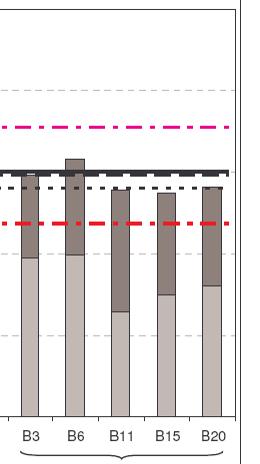
22 CW [kn] CAPWAP Combined: 1980, 1996, ,000 30,000 20,000 10,000 0 CW vs SLT combined (N=303) 0 10,000 20,000 30,000 40,000 SLT [kn] β = 2.33 D/L = 2 Measured/Predicted Bias (λ) = STD= COV= Φ = F.S. = 2.04 N =
23 Another statistics approach. Monte Carlo Simulation (MCS) Monte Carlo Simulation is a more rigorous method for the calculation of the resistance factors, in terms of providing an exact solution (to any degree of precision, given sufficient simulation size/time) MCS method can be applied to random samples with distributions that are neither normal nor lognormal or when the limit state equation is not linear.
24 Monte Carlo Simulation (MCS) overview: Describe a performance function g(x) (e.g. g = R Q) Compute g(x) for very large number of sets of randomly generated independent parameters (from mean λ and standard deviation σ) and trial φ Number of events when g(x) is unsatisfactory divided by number of simulation sets is Probability of Failure p(f) Compare p(f) to a Target Probability of Failure P(f) Adjust φ and repeat until p(f) < P(f)
25 Monte Carlo Simulation (MCS) results Monte Carlo B=2.33 B=3.0 bias p(f)=1.0% p(f)=0.1% p(f)=0.01% p(f)=0 Method λ COV-R max φ max φ max φ φ CAPWAP N=303 60,000 simulations CAPWAP N=303 1,000,000 simulations
26 Compare FOSM with Monte Carlo with AASHTO Monte Carlo Method B=2.33 bias p(f)=1.0% p(f)=0 λ COV-R max φ φ CAPWAP N= D/L=2 F.S. = FOSM N λ COV φ F.S. CAPWAP from 2004 published correlation paper AASHTO testing 2% φ = testing 100% φ = testing 2% plus a SLT φ = IBC F.S. =

27 Dynamic Pile Testing For each blow determine Capacity at time of testing
28 DRIVEN PILES Current Situation: Inefficient use of materials (design < 20% Fy) Proof Tests to { 2x Design } F.S. = 2 Tradition Conditions Favorable to Higher Capacities: Soft Rock, Till Hard Rock Soil Setup
 using IBC max allowable stresses (PPC Piles) Pile size f c (psi) assume prestress 700 psi Increase factor over 20 th Century loads Inch 5000 6000 7000")
29 Karl Higgins Competitive Advantages of High Capacity, Prestressed Precast Concrete Piles PDCA DICEP conference, Sept th Cent. loads Allowable Compression Capacities (tons) using IBC max allowable stresses (PPC Piles) Pile size f c (psi) assume prestress 700 psi Increase factor over 20 th Century loads Inch IBC safety factor is 2.0 for either static or dynamic test inch dia Drilled Shaft Vs. 14" PPC Pile (160 tons) $350/ cu. Yds. Final Design by IBC Potomac 76 Yard Pile Cap Costs Included for comparison 50 $35/lf Savings: 50% $32.67 $16.57 Diameter/Width Length (lf) Cost/unit Cost Per Ton 76-inch Shaft PPC-14 driven piles are least cost
30 Most Sites Have Set-up (defined as capacity gain with time) Caused by reduced effective stresses in soil during pile driving (temporary) Pore pressure effects - clay Arching (lateral motions) - sand Soil structure (e.g. chemical bonds) Cookie cutters Measure it by Dynamic Tests on Both End of Drive and Restrike


31 St. John s River Bridge test program Aug 11, bpf Sept x 0.5 inch c.e.pipe, ICE 120S 152 twice the Energy
 Total project (6")
 Ref: Scales & Wolcott, FDOT, presentation at PDCA Roundtable")
32 ST Johns River Bridge PDA test program $650,000 increased loads by 33% with substantially shorter piles (set-up considered) Total project (6 bridges): $130 million (estimate) $110 million (actual) $20 million (savings) Ref: Scales & Wolcott, FDOT, presentation at PDCA Roundtable Orlando 2004
33 Caution Sometimes the pile can lose capacity with time
34 Soils with relaxation potential Weathered bedrock formations Weathered shale is most susceptible Rule of thumb: more weathered bedrock = more relaxation Seeping water effectively softens bedrock surface High normal force after driving plastically creeps away with time; reduces friction Rock fracturing from driving adjacent piles Saturated dense to v.dense sands & sandy silts Due to negative pore water pressure during driving increases effective stresses of end bearing Pore water pressure equalizes after wait causing reduced soil strength
35 Dynamic Pile Monitoring For each blow determine Capacity at time of testing Pile integrity Pile stresses Hammer performance Last three items detect or prevent problems for driven piles


36 April 2004 Consequences of no redundancy, site variability, and only minimal testing, caused disastrous sudden failure. TAMPA Tribune Nov 23, 2004 Almost half of the foundations supporting the new elevated portion of the Lee Roy Selmon Expressway need major repairs, and the cost of fixing them has grown to $78 million. (eventual total cost was $120 M)
37 Dynamic Testing save $$, reduce risk Large Projects Pre-bid special test program optimizes design Pile length and size, pile type Establish design load (ultimate capacity) Evaluate set-up or relaxation (multi-day restikes) Early production pile tests (different hammer?) Establish driving criteria Evaluate hammer and procedures Confirm set-up or relaxation trends Periodic production pile tests Monitors hammer consistency Evaluate site variability Evaluate problem piles
38 Dynamic Testing save $$, reduce risk Small Projects Test early production piles Confirm design capacity achieved Evaluate set-up or relaxation Multi-hour restikes Restrike pile driven day before? Evaluate hammer and procedures Evaluate site variability Establish driving criteria Evaluate problem piles

39 SAVINGS FROM TESTING THE DRIVEN-PILE FOUNDATION FOR A HIGH-RISE BUILDING To be presented at IFCEE 2018, Orlando, March 2018 Authors: Van Komurka, & Adam Theiss, soils - silty sands to silt with sand, some lean clay in upper layers 16 inch x 0.5 inch x 61 ft steel pipes - concrete filled. Costs include cap
40 SAVINGS FROM TESTING THE DRIVEN-PILE FOUNDATION FOR A HIGH-RISE BUILDING Construction Control Method (CCM) Design Load (kips) # piles Total Cost Safety Foundation Testing Cost Factor Cost Cost Penalty WE, DLT, SLT ,513,762 2,277, ,260 0 WE & DLT ,983,308 2,795, , ,546 WE ,307,287 3,305,287 2, ,525 formula ,835,023 3,834, ,321,261 Above: Taking advantage of Set-up Below: Ignoring Set-up WE, DLT, SLT ,477,927 3,305, , ,165 WE & DLT ,361,508 4,231, ,339 1,847,746 WE ,992,764 4,990,764 2,000 2,479,002 formula ,814,673 5,814, ,300,911
41 SAVINGS FROM TESTING THE DRIVEN-PILE FOUNDATION FOR A HIGH-RISE BUILDING Construction Control Method (CCM) Safety Factor Design Load (kips) # piles Total Cost Cost Penalty Construction days Time Penalty (days) WE, DLT, SLT ,513, WE & DLT ,983, , WE ,307, , formula ,835,023 1,321, Above: Taking advantage of Set-up Below: Ignoring Set-up WE, DLT, SLT ,477, , WE & DLT ,361,508 1,847, WE ,992,764 2,479, formula ,814,673 3,300,


42 PDCA project of the year award (marine greater than $5 million) Ref: PDCA PILEDRIVER Issue 4, 2017 South Carolina Ports Authority Wando Terminal Improvements By Cape Romain Contractors In-situ dynamic testing carried an initial cost of $275,000, only 0.4 percent of the overall program budget. Ultimately, spending this 0.4 percent initially ended up saving SCPA 15 percent in construction costs.
43 Peter Narsavage Ohio Dept of Transportation 2011 PDCA seminar, Orlando Year Driven Pile Cost Testing Cost 2005 $10,705,041 $305, $18,836,927 $313, $15,948,151 $379, $26,591,945 $587,882 $2.5M / $123.6 M = 2% Test / driven pile cost 2009 $25,308,605 $450, $26,211,622 $518,557 Total $123,602,290 $2,556,288 Method AASHTO PHI (LRFD) Relative cost of piles Savings Formula (Gates) % Wave Equation % 2% PDA % 2 # PDA Ohio DOT % Savings $92,700, %PDA or SLT % PDA + SLT %
44 Advantages of Dynamic Testing More information faster and at lower cost Supplement or replace static tests Optimize foundation design Capacity & distribution from CAPWAP 40 years experience; large database Detect bad hammers Know driving stresses (compression-tension) Develop better installation procedures Detect pile damage Lowers risk of foundation failures Lower overall foundation costs
45 Conclusions Main cost is the foundation and its installation, not the testing cost. The benefit to cost ratio for dynamic testing is very favorable for the contractor, engineer, and the owner. Testing needed to get most benefit (low F.S. or high PHI), Significant set-up allows significant savings Dynamic Testing is highly beneficial (lowers total costs), particularly to design build or value engineering. Lowest project cost results from more testing Need to guard against relaxation in some soils fortunately fairly rare and soils generally known. Lack of adequate testing can cause failures, and the remediation can be very expensive. Testing reduces risk
46 Unknowns = Risk = Liability Actual testing removes unknowns and therefore reduces risks and liability State-of-Practice includes testing


47 One test result is worth a thousand expert opinions Werner Von Braun Father of the Saturn V rocket Measurements are better than Guesses
Dynamic Pile Testing ASTM D4945
 Dynamic Pile Testing ASTM D4945 Pile Driving Analyzer Garland Likins, Pile Dynamics, Inc. 2011 PDCA Professor s Institute Why test driven piles? Public assured of safe foundation (bridges, buildings, etc.)
LRFD GEOTECHNICAL IMPLEMENTATION
 LRFD GEOTECHNICAL IMPLEMENTATION Ching-Nien Tsai, P.E. LADOTD Pavement and Geotechnical Services In Conjunction with LTRC WHY LRFD FHWA deadline - October 2007 LRFD is a better method Risk is quantified
LRFD Calibration of Axially-Loaded Concrete Piles Driven into Louisiana Soils
 LRFD Calibration of Axially-Loaded Concrete Piles Driven into Louisiana Soils Louisiana Transportation Conference February 10, 2009 Sungmin Sean Yoon, Ph. D., P.E. (Presenter) Murad Abu-Farsakh, Ph. D.,
Calibration of Resistance Factors for Drilled Shafts for the 2010 FHWA Design Method
 Calibration of Resistance Factors for Drilled Shafts for the 21 FHWA Design Method Murad Y. Abu-Farsakh, Ph.D., P.E. Qiming Chen, Ph.D., P.E. Md Nafiul Haque, MS Feb 2, 213 213 Louisiana Transportation
CAPWAP rules Important!
 CAPWAP rules Important! Unit friction < 4 ksf (200 kpa ) for most soils QT (+TG) < Dmax, toe to assure activation QS < 0.2 inch (5 mm ) usually 0.1 inch; 2.5 mm SS, ST < 0.4 s/ft (1.3 s/m ) if higher,
Drilled Shaft Foundations in Limestone. Dan Brown, P.E., Ph.D. Dan Brown and Associates
 Drilled Shaft Foundations in Limestone Dan Brown, P.E., Ph.D. Dan Brown and Associates Foundation Engineering How we teach our students Fundamental understanding of soil and rock behavior (good!) Focus
INTRODUCTION TO STATIC ANALYSIS PDPI 2013
 INTRODUCTION TO STATIC ANALYSIS PDPI 2013 What is Pile Capacity? When we load a pile until IT Fails what is IT Strength Considerations Two Failure Modes 1. Pile structural failure controlled by allowable
PILE SETUP LA-1 EXPERIENCE. Ching-Nien Tsai, P.E.
 PILE SETUP LA-1 EXPERIENCE Ching-Nien Tsai, P.E. Bayou Lafourche Mississippi River GEOTECHNICAL INVESTIGATION PROGRAM 102 CPT soundings Depths from 100 feet to 200 feet 118 borings Depths from
Lesson 25. Static Pile Load Testing, O-cell, and Statnamic. Reference Manual Chapter 18
 Lesson 25 Static Pile Load Testing, O-cell, and Statnamic Reference Manual Chapter 18 STATIC LOAD TESTING Most accurate method to determine static pile capacity Perform at design or construction stage
Additional Pile Design Considerations
 Additional Pile Design Considerations PDCA 2015 Professor Driven Pile Institute Patrick Hannigan GRL Engineers, Inc. What Are Additional Pile Design Considerations? Time Dependent Soil Strength Changes
PDA Workshop: Stresses, Integrity, Energy and Capacity
 PDA Workshop: Stresses, Integrity, Energy and Capacity Ir Richard C L Yu IEM 2 Sep 2013 Dynamic Pile Monitoring For each blow determine Pile driving stresses Pile integrity Hammer performance Capacity
Implementation of Pile Setup in the LRFD Design of Driven Piles in Louisiana
 Implementation of Pile Setup in the LRFD Design of Driven Piles in Louisiana Md. Nafiul Haque (Ph.D. Candidate) Murad Y. Abu-Farsakh, Ph.D., P.E. March 1, 2016 Louisiana Transportation Conference OUTLINE
This document downloaded from vulcanhammer.net vulcanhammer.info Chet Aero Marine
 This document downloaded from vulcanhammer.net vulcanhammer.info Chet Aero Marine Don t forget to visit our companion site http://www.vulcanhammer.org Use subject to the terms and conditions of the respective
In-class Exercise. Problem: Select load factors for the Strength I and Service I Limit States for the. Loading Diagram for Student Exercise
 In-class Exercise Problem: Select load factors for the Strength I and Service I Limit States for the problem illustrated below. Loading Diagram for Student Exercise For this exercise, complete the following
LRFD Application in Driven Piles (Recent Development in Pavement & Geotech at LTRC)
") LRFD Application in Driven Piles (Recent Development in Pavement & Geotech at LTRC) 2007 Louisiana Transportation Engineering Conference February 12, 2007 Sungmin Sean Yoon, Ph. D., P.E. and Murad Abu-Farsakh,
LRFD Application in Driven Piles (Recent Development in Pavement & Geotech at LTRC) 2007 Louisiana Transportation Engineering Conference February 12, 2007 Sungmin Sean Yoon, Ph. D., P.E. and Murad Abu-Farsakh,
Role of the Geotechnical Consultant in Design Build Projects a General Contractors Geotechnical Engineer s Perspective
 Role of the Geotechnical Consultant in Design Build Projects a General Contractors Geotechnical Engineer s Perspective Steven R. Saye Kiewit Engineering Group, Inc. Design Build Geotechnical Goal All parties
THE STRUCTURAL DESIGN OF PILE FOUNDATIONS BASED ON LRFD FOR JAPANESE HIGHWAYS
 THE STRUCTURAL DESIGN OF PILE FOUNDATIONS BASED ON LRFD FOR JAPANESE HIGHWAYS Hideaki Nishida 1,Toshiaki Nanazawa 2, Masahiro Shirato 3, Tetsuya Kohno 4, and Mitsuaki Kitaura 5 Abstract One of the motivations
INDOT/Purdue Pile Driving Method for Estimation of Axial Capacity
 1 2015 Purdue Road School Transportation and Conference and Expo INDOT/Purdue Pile Driving Method for Estimation of Axial Capacity Zaheer, Mir, INDOT Salgado, Rodrigo, Purdue University Prezzi, Monica,
LOAD RESISTANCE FACTOR DESIGN (LRFD) FOR DRIVEN PILES BASED ON DYNAMIC METHODS WITH ASSESSMENT OF SKIN AND TIP RESISTANCE FROM PDA SIGNALS
 FOR DRIVEN PILES BASED ON DYNAMIC METHODS WITH ASSESSMENT OF SKIN AND TIP RESISTANCE FROM PDA SIGNALS") LOAD RESISTANCE FACTOR DESIGN (LRFD) FOR DRIVEN PILES BASED ON DYNAMIC METHODS WITH ASSESSMENT OF SKIN AND TIP RESISTANCE FROM PDA SIGNALS By ARIEL PEREZ PEREZ A THESIS PRESENTED TO THE GRADUATE SCHOOL
LOAD RESISTANCE FACTOR DESIGN (LRFD) FOR DRIVEN PILES BASED ON DYNAMIC METHODS WITH ASSESSMENT OF SKIN AND TIP RESISTANCE FROM PDA SIGNALS By ARIEL PEREZ PEREZ A THESIS PRESENTED TO THE GRADUATE SCHOOL
Calibration of Resistance Factor for Design of Pile Foundations Considering Feasibility Robustness
 Calibration of Resistance Factor for Design of Pile Foundations Considering Feasibility Robustness Hsein Juang Glenn Professor of Civil Engineering Clemson University 1 2 Outline of Presentation Background
Testing and Remediation Observational Method for the Design and Construction of Non-Redundant Pile Foundations
 29June211 Page 1 of 13 Testing and Remediation Observational Method for the Design and Construction of Non-Redundant Pile Foundations John H. Schmertmann, F.ASCE 1 and Carl P. Schmertmann 2 1 Professor
DRILLED DISPLACMENT PILE PERFORMANCE IN COASTAL PLAIN AND RESIDUAL SOILS
 DRILLED DISPLACMENT PILE PERFORMANCE IN COASTAL PLAIN AND RESIDUAL SOILS Presented by: W. Morgan NeSmith, P.E. Berkel & Company Contractors Inc. 770.941.5100 mnesmith@berkelapg.com SC Engineering Conference
TECHNICAL REPORT STANDARD PAGE
 TECHNICAL REPORT STANDARD PAGE 1. Report No. FHWA/LA.9/449 2. Government Accession No. 3. Recipient's Catalog No. 4. Title and Subtitle Calibration of Resistance Factors Needed in the LRFD Design of Driven
Geotechnical Engineering Report
 Geotechnical Engineering Report Turner Turnpike Widening Bridge D Bridge Crossing: South 209 th West Avenue Creek County, Oklahoma June 1, 2016 Terracon Project No. 04155197 Prepared for: Garver, LLC Tulsa,
vulcanhammer.info the website about Vulcan Iron Works Inc. and the pile driving equipment it manufactured Terms and Conditions of Use:
 this document downloaded from vulcanhammer.info the website about Vulcan Iron Works Inc. and the pile driving equipment it manufactured Terms and Conditions of Use: All of the information, data and computer
BACKGROUND AND INTRODUCTION
 WAVE MECHANICS As applied to pile testing 1 BACKGROUND AND INTRODUCTION Wave Mechanics 2 1 HISTORIC TOOLS AND MATERIALS Timber piles Drop Hammers 10 Days for the Romans to build the bridge over the Rhine
vulcanhammer.info the website about Vulcan Iron Works Inc. and the pile driving equipment it manufactured Terms and Conditions of Use:
 this document downloaded from vulcanhammer.info the website about Vulcan Iron Works Inc. and the pile driving equipment it manufactured Terms and Conditions of Use: All of the information, data and computer
SHEET PILE WALLS. Mehdi Mokhberi Islamic Azad University
 SHEET PILE WALLS Mehdi Mokhberi Islamic Azad University Lateral Support In geotechnical engineering, it is often necessary to prevent lateral soil movements. Tie rod Anchor Sheet pile Cantilever retaining
EVALUATION/MODIFICATION OF IDOT FOUNDATION PILING DESIGN
 CIVIL ENGINEERING STUDIES Illinois Center for Transportation Series No. 09-037 UILU-ENG-2009-2008 ISSN: 0197-9191 EVALUATION/MODIFICATION OF IDOT FOUNDATION PILING DESIGN AND CONSTRUCTION POLICY Prepared
Civil Engineering, Surveying and Environmental Consulting WASP0059.ltr.JLS.Mich Ave Bridge Geotech.docx
 2365 Haggerty Road South * Canton, Michigan 48188 P: 734-397-3100 * F: 734-397-3131 * www.manniksmithgroup.com August 29, 2012 Mr. Richard Kent Washtenaw County Parks and Recreation Commission 2330 Platt
Geotechnical Engineering Report
 Geotechnical Engineering Report Turner Turnpike Widening Polecat Creek Bridge (Bridge A) June 1, 2016 Terracon Project No. 04155197 Prepared for: Garver, LLC Prepared by: Terracon Consultants, Inc. TABLE
Seismic Pushover Analysis Using AASHTO Guide Specifications for LRFD Seismic Bridge Design
 Seismic Pushover Analysis Using AASHTO Guide Specifications for LRFD Seismic Bridge Design Elmer E. Marx, Alaska Department of Transportation and Public Facilities Michael Keever, California Department
June 9, R. D. Cook, P.Eng. Soils Engineer Special Services Western Region PUBLIC WORKS CANADA WESTERN REGION REPORT ON
 PUBLIC WORKS CANADA WESTERN REGION REPORT ON GEOTECHNICAL INVESTIGATION PROPOSED MARTIN RIVER BRIDGE MILE 306.7 MACKENZIE HIGHWAY Submitted by : R. D. Cook, P.Eng. Soils Engineer Special Services Western
S E C T I O N 1 2 P R O D U C T S E L E C T I O N G U I D E - H E L I C A L S C R E W P I L E F O U N D A T I O N S
 1. P R O D U C T S E L E C T I O N G U I D E - H E L I C A L S C R E W P I L E F O U N D A T I O N S Helical foundation pile includes a lead and extension(s). The lead section is made of a central steel
NCHRP LRFD Design Specifications for Shallow Foundations TRB AFS30 Committee Meeting January 26, 2011
 Geotechnical Engineering Research Laboratory Dept. of Civil and Environmental Engineering University of Massachusetts Lowell. NCHRP 24-31 LRFD Design Specifications for Shallow Foundations TRB AFS3 Committee
A Thesis presented to the Faculty of the Graduate School at the University of Missouri-Columbia
 LRFD for Settlement Analyses of Shallow Foundations and Embankments ------ Developed Resistance Factors for Consolidation Settlement Analyses A Thesis presented to the Faculty of the Graduate School at
Chapter (11) Pile Foundations
 Pile Foundations") Chapter (11) Introduction Piles are structural members that are made of steel, concrete, or timber. They are used to build pile foundations (classified as deep foundations) which cost more than shallow
Chapter (11) Introduction Piles are structural members that are made of steel, concrete, or timber. They are used to build pile foundations (classified as deep foundations) which cost more than shallow
vulcanhammer.info the website about Vulcan Iron Works Inc. and the pile driving equipment it manufactured Terms and Conditions of Use:
 this document downloaded from vulcanhammer.info the website about Vulcan Iron Works Inc. and the pile driving equipment it manufactured Terms and Conditions of Use: All of the information, data and computer
CORRELATION OF CAPWAP WITH STATIC LOAD TESTS
 CORRELATION OF CAPWAP WITH STATIC LOAD TESTS Garland Likins 1 and Frank Rausche 2 ABSTRACT Signal matching analysis such as CAPWAP is considered a standard procedure for the capacity evaluation from high
Developing a Resistance Factor for Mn/DOT s Pile Driving Formula
 2009-37 Developing a Resistance Factor for Mn/DOT s Pile Driving Formula Take the steps... Research...Knowledge...Innovative Solutions! Transportation Research Technical Report Documentation Page 1. Report
GEOTECHNICAL CRITERION FOR SERVICEABILITY LIMIT STATE OF HORIZONTALLY-LOADED DEEP FOUNDATIONS
 Abstract GEOTECHNICAL CITEION FO SEVICEABILITY LIMIT STATE OF HOIZONTALLY-LOADED DEEP FOUNDATIONS Masahiro Shirato 1, Shoichi Nakatani 2, Kenji Matsui 3, and Takashi Nakaura 4 This paper presents a first
Calibration of Resistance Factors for Driven Piles using Static and Dynamic Tests
 University of Arkansas, Fayetteville ScholarWorks@UARK Theses and Dissertations 12-2014 Calibration of Resistance Factors for Driven Piles using Static and Dynamic Tests Deshinka A. Bostwick University
EVALUATION OF LOAD TESTS FOR DRIVEN PILES FOR THE ALABAMA DEPARTMENT OF TRANSPORTATION. Jacob Wayne Hill
 EVALUATION OF LOAD TESTS FOR DRIVEN PILES FOR THE ALABAMA DEPARTMENT OF TRANSPORTATION Except where reference is made to the work of others, the work described in this thesis is my own or was done in collaboration
Geotechnical Engineering Report
 Geotechnical Engineering Report Turner Turnpike Widening Bridge B Bridge Crossing: South 257 th West Avenue Creek County, Oklahoma June 1, 2016 Terracon Project No. 04155197 Prepared for: Garver, LLC Tulsa,
Maximum Envelope of Lateral Resistance through Dynamic Increasing Energy Test in Piles
 Maximum Envelope of Lateral Resistance through Dynamic Increasing Energy Test in Piles R.M. Valverde, F. Massad Abstract. The traditional dynamic load test, based on the one-dimensional wave propagation
Neutral Plane Method for Drag Force of Deep Foundations and the AASHTO LRFD Bridge Design Specifications
 Neutral Plane Method for Drag Force of Deep Foundations and the AASHTO LRFD Bridge Design Specifications Timothy C. Siegel, P.E., G.E., D.GE Dan Brown and Associates, PC, Knoxville, Tennessee USA Rich
CPT Pore Water Pressure Correlations with PDA to Identify Pile Drivability Problem
 CPT Pore Water Pressure Correlations with PDA to Identify Pile Drivability Problem Fauzi Jarushi, Paul Cosentino, Edward Kalajian, Hadeel Dekhn Abstract At certain depths during large diameter displacement
Horizontal Directional Drilling: An Approach to Design and Construction. Presenter: John Briand, PE Co-Author: Danielle Neamtu, PE
 Horizontal Directional Drilling: An Approach to Design and Construction Presenter: John Briand, PE Co-Author: Danielle Neamtu, PE Presentation Outline General HDD overview Conceptual-level evaluation Detailed
Use of Ultra-High Performance Concrete in Geotechnical and Substructure Applications
 Use of Ultra-High Performance Concrete in Geotechnical and Substructure Applications i PI: Muhannad Suleiman Co-PI: Sri Sritharan Graduate Research Assistant: Thomas L. Vande Voort January 13, 29 IOWA
Liquefaction and Foundations
 Liquefaction and Foundations Amit Prashant Indian Institute of Technology Gandhinagar Short Course on Seismic Design of Reinforced Concrete Buildings 26 30 November, 2012 What is Liquefaction? Liquefaction
9.5 Compression Members
 9.5 Compression Members This section covers the following topics. Introduction Analysis Development of Interaction Diagram Effect of Prestressing Force 9.5.1 Introduction Prestressing is meaningful when
CPT Guide 5 th Edition. CPT Applications - Deep Foundations. Gregg Drilling & Testing, Inc. Dr. Peter K. Robertson Webinar # /2/2013
 Gregg Drilling & Testing, Inc. Site Investigation Experts CPT Applications - Deep Foundations Dr. Peter K. Robertson Webinar #6 2013 CPT Guide 5 th Edition Robertson & Cabal (Robertson) 5 th Edition 2012
World Academy of Science, Engineering and Technology International Journal of Geotechnical and Geological Engineering Vol:11, No:9, S.
 Design and Construction Validation of Pile Performance through High Strain Pile Dynamic Tests for both Contiguous Flight Auger and Drilled Displacement Piles S. Pirrello Abstract Sydney s booming real
IN SITU TESTING TECHNOLOGY FOR FOUNDATION & EARTHQUAKE ENGINEERING. Wesley Spang, Ph.D., P.E. AGRA Earth & Environmental, Inc.
 IN SITU TESTING TECHNOLOGY FOR FOUNDATION & EARTHQUAKE ENGINEERING Wesley Spang, Ph.D., P.E. AGRA Earth & Environmental, Inc. Portland, Oregon In situ testing of soil, which essentially consists of evaluating
Use of Launched Soil Nails to Stabilize Landslides in Summit County, Ohio
 Use of Launched Soil Nails to Stabilize Landslides in Summit County, Ohio Mitchell W. Weber, P.G. Gannett Fleming Engineers & Architects, P.C. Greg Bachman, P.E., P.S. County of Summit Engineer Robert
Bored Sockets in weathered Basalt
 Bored Sockets in weathered Basalt L. Maertens Manager Engineering Department Besix, Belgium Associate Professor Catholic University Leuven Keywords: sockets, open-end piles, tensile piles, basalt ABSTRACT:
INCREASE IN PILE CAPACITY WITH TIME IN MISSOURI RIVER ALLUVIUM
 INCREASE IN PILE CAPACITY WITH TIME IN MISSOURI RIVER ALLUVIUM Paul J. Axtell Jacob W. Owen Scott D. Vollink U.S. Army Corps of Engineers U.S. Army Corps of Engineers U.S. Army Corps of Engineers Kansas
Interpretation of Pile Integrity Test (PIT) Results
 Results") Annual Transactions of IESL, pp. 78-84, 26 The Institution of Engineers, Sri Lanka Interpretation of Pile Integrity Test (PIT) Results H. S. Thilakasiri Abstract: A defect present in a pile will severely
Annual Transactions of IESL, pp. 78-84, 26 The Institution of Engineers, Sri Lanka Interpretation of Pile Integrity Test (PIT) Results H. S. Thilakasiri Abstract: A defect present in a pile will severely
FHWA Bridge Design Guidance No. 1 Revision Date: July 21, Load Rating Evaluation of Gusset Plates in Truss Bridges
 FHWA Bridge Design Guidance No. 1 Revision Date: July 21, 2008 Load Rating Evaluation of Gusset Plates in Truss Bridges By Firas I. Sheikh Ibrahim, PhD, PE Part B Gusset Plate Resistance in Accordance
Deep Foundations 2. Load Capacity of a Single Pile
 Deep Foundations 2 Load Capacity of a Single Pile All calculations of pile capacity are approximate because it is almost impossible to account for the variability of soil types and the differences in the
Design of Reinforced Soil Walls By Lrfd Approach
 IOSR Journal of Mechanical and Civil Engineering (IOSR-JMCE) ISSN: 2278-1684, PP: 16-26 www.iosrjournals.org Design of Reinforced Soil Walls By Lrfd Approach A.D. Maskar 1, N.T. Suryawanshi 2 1 Assistant
African Meetinghouse ACCESSING HISTORY. Richard Pizzi, P.E. Special Thanks to Rick Wilhelmsen GEOTECHNICAL CONSULTANTS, INC
 African Meetinghouse ACCESSING HISTORY Richard Pizzi, P.E. Special Thanks to Rick Wilhelmsen GEOTECHNICAL CONSULTANTS, INC SOIL NAIL WALL CONSTRUCTION SOIL NAIL WALL CONSTRUCTION SOIL NAIL WALL CONSTRUCTION
R.M.HARW & ASSOCIATES LTD. GEOTECHNICAL INVESTIGATION PROPOSED BRIDGE SITE. HELAVA CREEKl MILE MACKENZIE HIGHWAY E-2510 OCTOBER 16, 1973
 El R.M.HARW & ASSOCIATES LTD. GEOTECHNICAL INVESTIGATION PROPOSED BRIDGE SITE HELAVA CREEKl MILE 616.4 MACKENZIE HIGHWAY E-2510 OCTOBER 16, 1973 R,M,HARDV & ASSOCIATES LTD. CONSULTING ENGINEERING & TESTING
50 ksi Steel H-pile Capacity
 50 ksi Steel H-pile Capacity FINAL REPORT June 30, 2015 Kent A Harries, PhD, FACI, FIIFC, PEng Jeen-Shang Lin, ScD, PE Marwa Hasanzoi, MSCE COMMONWEALTH OF PENNSYLVANIA DEPARTMENT OF TRANSPORTATION CONTRACT
Reliability Considerations for Steel Frames Designed with Advanced Analysis
 Reliability Considerations for Steel Frames Designed with Advanced Analysis Stephen G. Buonopane Benjamin W. Schafer Takeru Igusa Dept. of Civil Engineering Johns Hopkins University Features of Advanced
Rapid Load Test from Theory to Practice in Singapore. 1. Introduction
 GEOSS SEMINAR 2014 on PILE LOAD TESTS IN SINGAPORE Presentation on Rapid Load Test from Theory to Practice in Singapore By Dr. Chew Soon Hoe Assistant Professor National University of Singapore ceecsh@nus.edu.sg
Appendix K Design Examples
 Appendix K Design Examples Example 1 * Two-Span I-Girder Bridge Continuous for Live Loads AASHTO Type IV I girder Zero Skew (a) Bridge Deck The bridge deck reinforcement using A615 rebars is shown below.
Presented by: Civil Engineering Academy
 Presented by: Civil Engineering Academy Structural Design and Material Properties of Steel Presented by: Civil Engineering Academy Advantages 1. High strength per unit length resulting in smaller dead
Appendix J. Example of Proposed Changes
 Appendix J Example of Proposed Changes J.1 Introduction The proposed changes are illustrated with reference to a 200-ft, single span, Washington DOT WF bridge girder with debonded strands and no skew.
 Project: ITHACA-TOMPKINS REGIONAL AIRPORT EXPANSION Project Location: ITHACA, NY Project Number: 218-34 Key to Soil Symbols and Terms TERMS DESCRIBING CONSISTENCY OR CONDITION COARSE-GRAINED SOILS (major
Toe Protection for H-piles on Sloping Bedrock at Rainy River
 Toe Protection for H-piles on Sloping Bedrock at Rainy River Jon E. Bischoff, Bengt H. Fellenius, Richard E. Riker Proceedings of Deep Foundations Institute Annual Meeting, Pittsburgh October 18-20, 1993
Why are We Here? AASHTO LRFD Bridge Design Specifications Metal Pipe Section 12.7 Concrete Pipe Section Plastic Pipe Section 12.12
 Direct Design and Indirect Design of Concrete Pipe Part 1 Josh Beakley March 2011 Why are We Here? AASHTO LRFD Bridge Design Specifications Metal Pipe Section 12.7 Concrete Pipe Section 12.10 Plastic Pipe
Discussion: behaviour of jacked and driven piles in sandy soil
 Title Discussion: behaviour of jacked and driven piles in sandy soil Author(s) Yang, J; Tham, LG; Lee, PKK; Chan, ST; Yu, F Citation Géotechnique, 27, v. 7 n., p. 47-478 Issued Date 27 URL http://hdl.handle.net/1722/7161
Chapter 12 Subsurface Exploration
 Page 12 1 Chapter 12 Subsurface Exploration 1. The process of identifying the layers of deposits that underlie a proposed structure and their physical characteristics is generally referred to as (a) subsurface
Comparisons of rapid load test, dynamic load test and static load test on driven piles
 Comparisons of rapid load test, dynamic load test and static load test on driven piles Bamrungwong, C., Chaisukhang, J. & Janmonta, K. Department of Rural Roads, Thailand Kitiyodom, P. Geotechnical & Foundation
Design of RC Retaining Walls
 Lecture - 09 Design of RC Retaining Walls By: Prof Dr. Qaisar Ali Civil Engineering Department UET Peshawar www.drqaisarali.com 1 Topics Retaining Walls Terms Related to Retaining Walls Types of Retaining
Module 9 : Foundation on rocks. Content
 FOUNDATION ON ROCKS Content 9.1 INTRODUCTION 9.2 FOUNDATION TYPES ON ROCKS 9.3 BEARING CAPCITY- SHALLOW FOUNDATION 9.3.1 Ultimate bearing capacity 9.3.2 Safe bearing pressure 9.3.3 Estimation of bearing
Understanding Dynamic Pile Testing and Driveability
 008-015 understand dynamic 5/30/06 5:10 PM Page 8 Understanding Dynamic Pile Testing and Driveability... By: Engr. Dr Sam Ming Tuck MIEM, P.Eng INTRODUCTION Traditionally, piles are static load tested
PECivilExam.com. Copyright 2015 Pecivilexam.com all rights reserved- E-Book Geotechnical Depth Exam: 80 problems
 PECivilExam.com PE Civil Exam 80- Geotechnical Questions & Answers (pdf Format) For Depth Exam (Evening Session) PE Civil Depth Exam (Evening Session): This practice exam contains 80- Geotechnical questions,
M E M O R A N D U M. Mr. Jonathan K. Thrasher, P.E., Mr. Ian Kinnear, P.E. (FL) PSI
 PSI") M E M O R A N D U M TO: FROM: Mr. Mark Schilling Gulf Interstate Engineering Mr. Jonathan K. Thrasher, P.E., Mr. Ian Kinnear, P.E. (FL) PSI DATE: November 11, 2014 RE: Summary of Findings Geotechnical
M E M O R A N D U M TO: FROM: Mr. Mark Schilling Gulf Interstate Engineering Mr. Jonathan K. Thrasher, P.E., Mr. Ian Kinnear, P.E. (FL) PSI DATE: November 11, 2014 RE: Summary of Findings Geotechnical
This document downloaded from vulcanhammer.net vulcanhammer.info Chet Aero Marine
 This document downloaded from vulcanhammer.net vulcanhammer.info Chet Aero Marine Don t forget to visit our companion site http://www.vulcanhammer.org Use subject to the terms and conditions of the respective
SHEAR STRENGTH OF SOIL
 Soil Failure Criteria SHEAR STRENGTH OF SOIL Knowledge about the shear strength of soil important for the analysis of: Bearing capacity of foundations, Slope stability, Lateral pressure on retaining structures,
Geotechnical Aspects of the Seismic Update to the ODOT Bridge Design Manual. Stuart Edwards, P.E Geotechnical Consultant Workshop
 Geotechnical Aspects of the Seismic Update to the ODOT Bridge Design Manual Stuart Edwards, P.E. 2017 Geotechnical Consultant Workshop Changes Role of Geotechnical Engineer Background Methodology Worked
However, reliability analysis is not limited to calculation of the probability of failure.
 Probabilistic Analysis probabilistic analysis methods, including the first and second-order reliability methods, Monte Carlo simulation, Importance sampling, Latin Hypercube sampling, and stochastic expansions
vulcanhammer.net This document downloaded from
 This document downloaded from vulcanhammer.net since 1997, your source for engineering information for the deep foundation and marine construction industries, and the historical site for Vulcan Iron Works
Reliability Analysis of Anchored and Cantilevered Flexible Retaining Structures
 LSD2003: International Workshop on Limit State Design in Geotechnical Engineering Practice Phoon, Honjo & Gilbert (eds) 2003 World Scientific Publishing Company Reliability Analysis of Anchored and Cantilevered
ADSC Research Project Update: Rock Sockets in the Southeastern U.S.
 ADSC Research Project Update: Rock Sockets in the Southeastern U.S. W. Robert Thompson, III, P.E., D.GE, M.ASCE 1 ABSTRACT The bearing capacity of drilled shafts in rock has traditionally been assessed
Appendix J. Geological Investigation
 Appendix J Geological Investigation Appendix J Geological Environment Table of Contents Page 1 INTRODUCTION...J-1 1.1 Purpose of the Investigation...J-1 1.2 Scope of the Investigation...J-1 2 METHODO OF
Chapter 5 Shear Strength of Soil
 Page 5 Chapter 5 Shear Strength of Soil. The internal resistance per unit area that the soil mass can offer to resist failure and sliding along any plane inside it is called (a) strength (b) shear strength
Evaluation of Geotechnical Hazards
 Evaluation of Geotechnical Hazards by Geoffrey R. Martin Appendix B: Evaluation of Geotechnical Hazards Describes Evaluation Procedures Soil Liquefaction Soil Settlement Surface Fault Rupture Flooding
FHWA/IN/JTRP-2008/5. Final Report. Dongwook Kim Rodrigo Salgado
 FHWA/IN/JTRP-2008/5 Final Report LIMIT STATES AND LOAD AND RESISTANCE DESIGN OF SLOPES AND RETAINING STRUCTURES Dongwook Kim Rodrigo Salgado January 2009 INDOT Research TECHNICAL Summary Technology Transfer
Clayey sand (SC)
") Pile Bearing Capacity Analysis / Verification Input data Project Task : PROJECT: "NEW STEAM BOILER U-5190 Part : A-1 Descript. : The objective of this Analysis is the Pile allowable bearing Capacity Analysis
Pile Bearing Capacity Analysis / Verification Input data Project Task : PROJECT: "NEW STEAM BOILER U-5190 Part : A-1 Descript. : The objective of this Analysis is the Pile allowable bearing Capacity Analysis
Use of RMR to Improve Determination of the Bearing Resistance of Rock
 Creating Value Delivering Solutions Use of RMR to Improve Determination of the Bearing Resistance of Rock Scott Zang, P.E. Michael Baker Jr., Inc. ASD Design Q v allowable is a presumptive allowable bearing
(THIS IS ONLY A SAMPLE REPORT OR APPENDIX OFFERED TO THE USERS OF THE COMPUTER PROGRAM
 C A U T I O N!! (THIS IS ONLY A SAMPLE REPORT OR APPENDIX OFFERED TO THE USERS OF THE COMPUTER PROGRAM EQLique&Settle2. THE AUTHOR IS HEREBY RELEASED OF ANY LIABILITY FOR ANY INCORRECT USE OF THIS SAMPLE
B-1 SURFACE ELEVATION
 5A 5B LOGGED BY El. S. Bhangoo DRILLING CONTRACTOR Pitcher Drilling DRILLING METHOD Rotary Wash BEGIN DATE 12-14-12 SAMPLER TYPE(S) AND SIZE(S) (ID) SPT, MC BOREHOLE BACKFILL AND COMPLETION COMPLETION
A presentation of UniPile software for calculation of Capacity, Drag Force, Downdrag, and Settlement for Piles and Piled Foundations
 528 River Road, Ottawa, Ontario, Canada, K1V 1E9 E: info@unisoftgs.com A presentation of UniPile software for calculation of Capacity, Drag Force, Downdrag, and Settlement for Piles and Piled Foundations
Summary and Review of Part II of the Symposium on Pile Foundations
 Summary and Review of Part II of the Symposium on Pile Foundations G. A. LEONARDS, Purdue University PILE FOUNDATIONS share with cellular cofferdams the distinction of yielding most reluctantly to the
CHAPTER 8 CALCULATION THEORY
 CHAPTER 8 CALCULATION THEORY. Volume 2 CHAPTER 8 CALCULATION THEORY Detailed in this chapter: the theories behind the program the equations and methods that are use to perform the analyses. CONTENTS CHAPTER
Improving site specific modified driving formulae using high frequency displacement monitoring
 Proc. 20 th NZGS Geotechnical Symposium. Eds. GJ Alexander & CY Chin, Napier Improving site specific modified driving formulae using high frequency displacement monitoring R Damen Brian Perry Civil, Auckland,
SELMON EXPRESSWAY, TAMPA: CASE HISTORY OF DRILLED SHAFT DESIGN FOR EXTREME VARIABILITY
 SELMON EXPRESSWAY, TAMPA: CASE HISTORY OF DRILLED SHAFT DESIGN FOR EXTREME VARIABILITY David S. Graham, Dan Brown and Associates, PC, Chattanooga, Tennessee Steven D. Dapp, Dan Brown and Associates, PC,