Use of Ultra-High Performance Concrete in Geotechnical and Substructure Applications
|
|
|
- Silvester Douglas
- 5 years ago
- Views:
Transcription
1 Use of Ultra-High Performance Concrete in Geotechnical and Substructure Applications i PI: Muhannad Suleiman Co-PI: Sri Sritharan Graduate Research Assistant: Thomas L. Vande Voort January 13, 29 IOWA STATE UNIVERSITY
2 Research Funding Seed funding received from IHRB for a highrisk, high-reward project that can lead to substantive advancements in highway transportation 2
3 Objectives Demonstrate the potential use of UHPC in geotechnical applications Evaluate the behavior of UHPC piles using large-scale tests and analytical procedures


4 Motivation Grand d Challenges issued by AASHTO 25: Extending service life of bridges to 75 years with minimal maintenance Optimizing structural systems using new materials Piles made of conventional materials have suffered damage
5 Why UHPC? Property UHPC HPC Normal Concrete Compressive Strength 26-3 ksi ksi 4-8 ksi Tensile Strength 1.7 ksi.8-.9 ksi.3-.7 ksi Elastic Modulus 8 ksi ksi ksi Durability Up to 4x lower Up to 7x lower 1 arameter Re elative to Normal Con ncrete P UH HPC HPC Normal Con ncrete Chloride Ion Penetration Depth PC UH HPC Normal Con ncrete PC UH HPC Oxygen Permeabilty Water Absorption Carbonation Depth (3 years) Normal Con ncrete UHPC HPC Normal Con ncrete PC UH HPC Normal Con ncrete Reinforcement Corrosion Rate
6 Tasks Conduct a literature review on the use of UHPC in super- and any sub-structural systems related to transportation structures in the United States and abroad Design of UHPC pile section Conduct comparative driveability study for UHPC and other piles Conduct laboratory tests on UHPC pile elements Conduct dynamic tests (PDA/CAPWAP) on UHPC and steel piles Perform large-scale vertical and lateral load tests on UHPC piles
7 Pile Section Shapes Considered Simple H-Shape X-Shape Tapered H-Shape
8 Final Section Properties Parameter Steel HP 1 x 57 UHPC Tapered H-Shape Area 16.8 in in 2 Weight/ft 57.2 lb 61.1 lb Moment of Inertia 294 in in 4 Stiffness Term (E I) kip in kip in 2
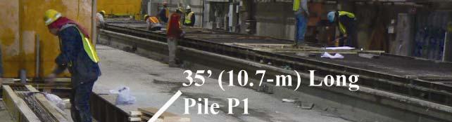
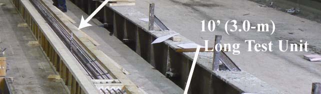
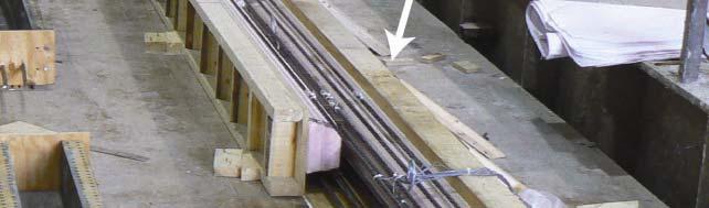
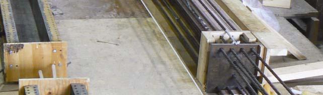

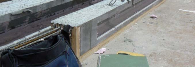
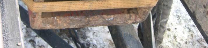
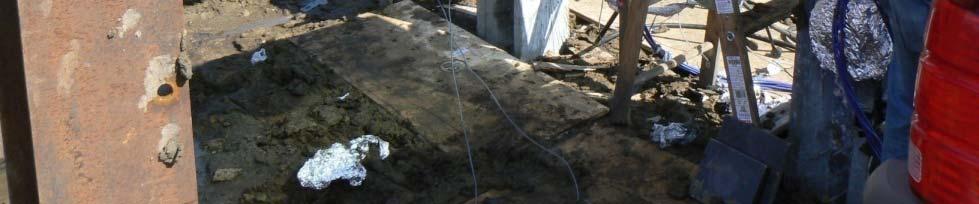
9 Construction b


10 Laboratory Testing Cells Top Tilt Gauge Curvature, φ (mm -1 ) DCDTs String Deflection Gauges Moment, M (in k kip) Calculated Response Lab Test Measured Data Moment, M (kn m) Curvature, φ (in -1 )
11 Field Investigation: US63 Oskaloosa, IA
12 Site Soil Profile SPT Blow Count (blows/ft) Tip Resistance, q 2 c (ton/ft ) Friction, f 2 s (ton/ft ) Friction Ratio, F r (%) Soil Classification Undrained Shear Strength, s u (psi) % 5% 1% 15% Clay Friction Angle, φ Sensitive Fine Grained Clay Depth (ft) 2 Sand Sandy Silt to Clayey Silt 2 6 Depth (m) 25 Sand to Silty Sand Tip Resistance, q c (kpa) Friction, f s (kpa) 3 Sandy Silt to Clayey Silt Very Stiff 1 Fine Clay Grained Gravelly Sand to Sand Undrained Shear Strength, s u (kpa)
13 Field Testing Plan Reaction Pile Reaction Beam Reaction Pile Reaction Pile 6.5 ft 6.5 ft 5. ft 4. ft Unit UHPC 1 Steel Pile Reaction Pile Unit UHPC 2


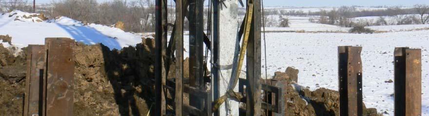
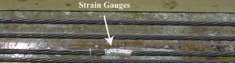
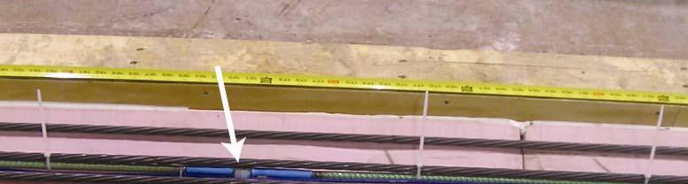
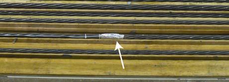
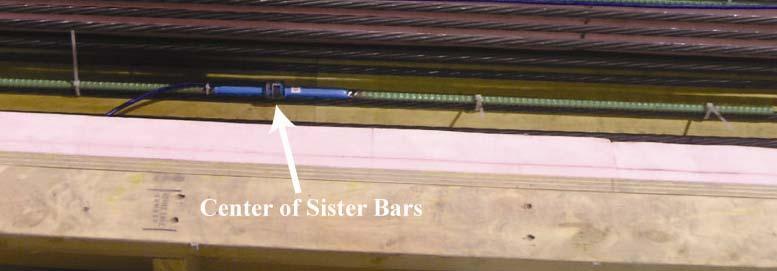
14 Driving of UHPC and Steel Piles Hammer Leads Pile PDA Accelerometer PDA Strain Gauge
15 Driving Logs Cum Blows etration Depth (m) Pen Blows/.3m of Steel HP 1x57 Blows/.3 m of UHPC 1 Cum blows for steel HP 1x57 Cum blows for UHPC h (ft) Pen netration Dept Blows/ ft
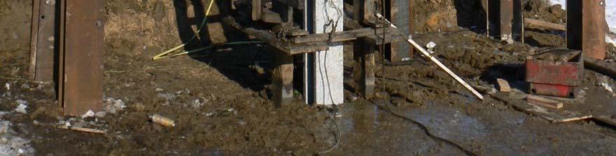
16 Driving

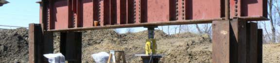
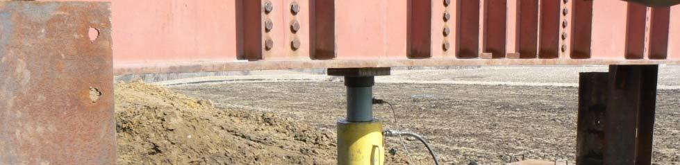
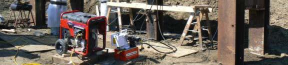
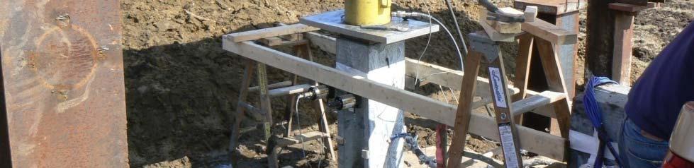
17 Vertical Load Tests
18 Load-Displacement Relationship Load (kn) Load (kn) Extrapolation Displacement (mm) Displacement (in.) Displacement (mm) Displace ment (in.) Davi avisson Pile Capacity = 198 Kips Davisson Failure Crit Criterion Davisson son Failure Criterion 7.7 Davisson Pile Capacity = 369 Kips Load (Kips) Load (Kips) UHPC Steel Pile
19 Load Transfer Depth (m) Vertical Load (kn) Ground Surface Vertical Load (Kips) Depth (ft) Load (kn)

20 Lateral Load Test
 11 1 1 2 3 4 5 6 7 8 9 24 22 9 2 8 18 Lateral Load (kn) 7 6 5 4 3 2")
 Bundle of wires 5 1 15 2 25 (b) Lateral")
21 UHPC Pile Lateral Load-Displacement Lateral Displacement (in.) Lateral Load (kn) UHPC 1 UHPC La ateral Load (K Kips) Shear cracks Bundle of wires (a) Bundle of wires (b) Lateral Displacement (mm)
22 UHPC Pile Lateral Load-Displacement Strain (με) De epth (m) Ground Surface 15.9 kn 27.9 kn 4.7 kn 55.9 kn 68.8 kn 77.8 kn 92.7 kn 11.2 kn epth (ft) D
23 Questions
This procedure covers the determination of the moment of inertia about the neutral axis.
 327 Sample Problems Problem 16.1 The moment of inertia about the neutral axis for the T-beam shown is most nearly (A) 36 in 4 (C) 236 in 4 (B) 136 in 4 (D) 736 in 4 This procedure covers the determination
INTERFACE STRESSES BETWEEN SOIL AND LARGE DIAMETER DRILLED SHAFT UNDER LATERAL LOADING
 INTERFACE STRESSES BETWEEN SOIL AND LARGE DIAMETER DRILLED SHAFT UNDER LATERAL LOADING Kerop D. Janoyan 1, P.E., Member, Geo-Institute, and Matthew J. Whelan 2 ABSTRACT: Results are presented of a field
Lesson 25. Static Pile Load Testing, O-cell, and Statnamic. Reference Manual Chapter 18
 Lesson 25 Static Pile Load Testing, O-cell, and Statnamic Reference Manual Chapter 18 STATIC LOAD TESTING Most accurate method to determine static pile capacity Perform at design or construction stage
INCREASE IN PILE CAPACITY WITH TIME IN MISSOURI RIVER ALLUVIUM
 INCREASE IN PILE CAPACITY WITH TIME IN MISSOURI RIVER ALLUVIUM Paul J. Axtell Jacob W. Owen Scott D. Vollink U.S. Army Corps of Engineers U.S. Army Corps of Engineers U.S. Army Corps of Engineers Kansas
Cone Penetration Test (CPT) Interpretation
 Interpretation") Cone Penetration Test (CPT) Interpretation Gregg uses a proprietary CPT interpretation and plotting software. The software takes the CPT data and performs basic interpretation in terms of soil behavior
Cone Penetration Test (CPT) Interpretation Gregg uses a proprietary CPT interpretation and plotting software. The software takes the CPT data and performs basic interpretation in terms of soil behavior
Experimental Investigation of Interface Stresses between Soil and Laterally Loaded Shaft
 Experimental Investigation of Interface Stresses between Soil and Laterally Loaded Shaft K.D. Janoyan & M.J. Whelan Clarkson University, Potsdam, New York, USA ABSTRACT: Presented are results of a field
ANALYSIS OF LATERALLY LOADED FIXED HEADED SINGLE FLOATING PILE IN MULTILAYERED SOIL USING BEF APPROACH
 INDIAN GEOTECHNICAL SOCIETY, KOLKATA CHAPTER GEOTECHNICS FOR INFRASTRUCTURE DEVELOPMENT KOLKATA 11 th 12 th March 2016, Kolkata, West Bengal, India ANALYSIS OF LATERALLY LOADED FIXED HEADED SINGLE FLOATING
Liquefaction and Foundations
 Liquefaction and Foundations Amit Prashant Indian Institute of Technology Gandhinagar Short Course on Seismic Design of Reinforced Concrete Buildings 26 30 November, 2012 What is Liquefaction? Liquefaction
FINITE ELEMENT ANALYSIS OF ARKANSAS TEST SERIES PILE #2 USING OPENSEES (WITH LPILE COMPARISON)
") FINITE ELEMENT ANALYSIS OF ARKANSAS TEST SERIES PILE #2 USING OPENSEES (WITH LPILE COMPARISON) Ahmed Elgamal and Jinchi Lu October 07 Introduction In this study, we conduct a finite element simulation
FINITE ELEMENT ANALYSIS OF ARKANSAS TEST SERIES PILE #2 USING OPENSEES (WITH LPILE COMPARISON) Ahmed Elgamal and Jinchi Lu October 07 Introduction In this study, we conduct a finite element simulation
Jose Brito, Cenor, Portugal
 Jose Brito, Cenor, Portugal Carsten S. Sorensen, COWI, Denmark In this example it is asked to design a square pad foundation according to Eurocode 7. The aim is the evaluation of the foundation width with
Type approval granted by the Finnish Ministry of the Environment
 RR Piling Manual 2 Type approval granted by the Finnish Ministry of the Environment 2..02. RR Piling Manual 1. General This manual deals with impact-driven RR piles. It is an abridgement of the RR Piling
Table 3. Empirical Coefficients for BS 8002 equation. A (degrees) Rounded Sub-angular. 2 Angular. B (degrees) Uniform Moderate grading.
 Rounded Sub-angular. 2 Angular. B (degrees) Uniform Moderate grading.") Hatanaka and Uchida (1996); ' 20N 20 12N 20 ' 45 A lower bound for the above equation is given as; 12N 15 ' 45 Table 3. Empirical Coefficients for BS 8002 equation A Angularity 1) A (degrees) Rounded 0
Hatanaka and Uchida (1996); ' 20N 20 12N 20 ' 45 A lower bound for the above equation is given as; 12N 15 ' 45 Table 3. Empirical Coefficients for BS 8002 equation A Angularity 1) A (degrees) Rounded 0
NEW DOWN-HOLE PENETROMETER (DHP-CIGMAT) FOR CONSTRUCTION APPLICATIONS
 FOR CONSTRUCTION APPLICATIONS") NEW DOWN-HOLE PENETROMETER (DHP-CIGMAT) FOR CONSTRUCTION APPLICATIONS 1 2 C. Vipulanandan 1, Ph.D., M. ASCE and Omer F. Usluogullari 2 Chairman, Professor, Director of Center for Innovative Grouting Materials
NEW DOWN-HOLE PENETROMETER (DHP-CIGMAT) FOR CONSTRUCTION APPLICATIONS 1 2 C. Vipulanandan 1, Ph.D., M. ASCE and Omer F. Usluogullari 2 Chairman, Professor, Director of Center for Innovative Grouting Materials
BACKGROUND AND INTRODUCTION
 WAVE MECHANICS As applied to pile testing 1 BACKGROUND AND INTRODUCTION Wave Mechanics 2 1 HISTORIC TOOLS AND MATERIALS Timber piles Drop Hammers 10 Days for the Romans to build the bridge over the Rhine
CPT Data Interpretation Theory Manual
 CPT Data Interpretation Theory Manual 2016 Rocscience Inc. Table of Contents 1 Introduction... 3 2 Soil Parameter Interpretation... 5 3 Soil Profiling... 11 3.1 Non-Normalized SBT Charts... 11 3.2 Normalized
EFFECT OF SOIL TYPE LOCATION ON THE LATERALLY LOADED SINGLE PILE
 International Journal of Civil Engineering and Technology (IJCIET) Volume 9, Issue 12, December 2018, pp. 1196 1205, Article ID: IJCIET_09_12 122 Available online at http://www.ia aeme.com/ijciet/issues.asp?jtype=ijciet&vtype=
Chapter 12 Subsurface Exploration
 Page 12 1 Chapter 12 Subsurface Exploration 1. The process of identifying the layers of deposits that underlie a proposed structure and their physical characteristics is generally referred to as (a) subsurface
S E C T I O N 1 2 P R O D U C T S E L E C T I O N G U I D E - H E L I C A L S C R E W P I L E F O U N D A T I O N S
 1. P R O D U C T S E L E C T I O N G U I D E - H E L I C A L S C R E W P I L E F O U N D A T I O N S Helical foundation pile includes a lead and extension(s). The lead section is made of a central steel
Analysis of the horizontal bearing capacity of a single pile
 Engineering manual No. 16 Updated: 07/2018 Analysis of the horizontal bearing capacity of a single pile Program: Soubor: Pile Demo_manual_16.gpi The objective of this engineering manual is to explain how
K Design Graphs and Charts for Raft Foundations Spanning Local Depressions
 K Design Graphs and Charts for Raft Foundations Spanning Local Depressions The reader is advised to read the text in Chapter 13 before using these charts. The charts and figures are repeated here for quick
CPT: Geopractica Contracting (Pty) Ltd Total depth: m, Date:
 Ltd Total depth: m, Date:") The plot below presents the cross correlation coeficient between the raw qc and fs values (as measured on the field). X axes presents the lag distance (one lag is the distance between two sucessive CPT
The plot below presents the cross correlation coeficient between the raw qc and fs values (as measured on the field). X axes presents the lag distance (one lag is the distance between two sucessive CPT
Assessment of Calculation Procedures for Piles in Clay based on Static Loading Tests Anders Hust Augustesen
 Assessment of Calculation Procedures for Piles in Clay based on Static Loading Tests By Anders Hust Augustesen 1 Agenda Presentation of calculation procedures Basis for the evaluation of the calculation
MECE 3321 MECHANICS OF SOLIDS CHAPTER 3
 MECE 3321 MECHANICS OF SOLIDS CHAPTER 3 Samantha Ramirez TENSION AND COMPRESSION TESTS Tension and compression tests are used primarily to determine the relationship between σ avg and ε avg in any material.
LOAD RESISTANCE FACTOR DESIGN (LRFD) FOR DRIVEN PILES BASED ON DYNAMIC METHODS WITH ASSESSMENT OF SKIN AND TIP RESISTANCE FROM PDA SIGNALS
 FOR DRIVEN PILES BASED ON DYNAMIC METHODS WITH ASSESSMENT OF SKIN AND TIP RESISTANCE FROM PDA SIGNALS") LOAD RESISTANCE FACTOR DESIGN (LRFD) FOR DRIVEN PILES BASED ON DYNAMIC METHODS WITH ASSESSMENT OF SKIN AND TIP RESISTANCE FROM PDA SIGNALS By ARIEL PEREZ PEREZ A THESIS PRESENTED TO THE GRADUATE SCHOOL
LOAD RESISTANCE FACTOR DESIGN (LRFD) FOR DRIVEN PILES BASED ON DYNAMIC METHODS WITH ASSESSMENT OF SKIN AND TIP RESISTANCE FROM PDA SIGNALS By ARIEL PEREZ PEREZ A THESIS PRESENTED TO THE GRADUATE SCHOOL
Analysis of Pile Foundation Subjected to Lateral and Vertical Loads
 Analysis of Pile Foundation Subjected to Lateral and Vertical Loads Thadapaneni Kanakeswararao 1, B.Ganesh 2 1,2 Department of soil mechanics and foundation engg, Lenora college of Engineering and technology,
Sabah Shawkat Cabinet of Structural Engineering Walls carrying vertical loads should be designed as columns. Basically walls are designed in
 Sabah Shawkat Cabinet of Structural Engineering 17 3.6 Shear walls Walls carrying vertical loads should be designed as columns. Basically walls are designed in the same manner as columns, but there are
5. What is the moment of inertia about the x - x axis of the rectangular beam shown?
 1 of 5 Continuing Education Course #274 What Every Engineer Should Know About Structures Part D - Bending Strength Of Materials NOTE: The following question was revised on 15 August 2018 1. The moment
Congreso Internacional de Fundaciones Profundas de Bolivia Santa Cruz, Bolivia, 12 al 15 de Mayo de 2015 Day 1: Software Demonstrations
 Applications of Stress Wave Theory to Deep Foundations with an Emphasis on The Wave Equation (GRLWEAP) Congreso Internacional de Fundaciones Profundas de Bolivia Santa Cruz, Bolivia, 12 al 15 de Mayo de
Implementation of Laterally Loaded Piles in Multi-Layer Soils
 Implementation of Laterally Loaded Piles in Multi-Layer Soils JTRP SPR- 3261 Final SAC meeting SAC members Mir Zaheer and Keith Hoernschemeyer Purdue University Introduction Analysis developed for the
Experimental Study on The Seismic Assessment of Pile Foundation in Volcanic Ash Ground
 Experimental Study on The Seismic Assessment of Pile Foundation in Volcanic Ash Ground Takuya EGAWA, Satoshi NISHIMOTO & Koichi TOMISAWA Civil Engineering Research Institute for Cold Region, Public Works
Implementation of Pile Setup in the LRFD Design of Driven Piles in Louisiana
 Implementation of Pile Setup in the LRFD Design of Driven Piles in Louisiana Md. Nafiul Haque (Ph.D. Candidate) Murad Y. Abu-Farsakh, Ph.D., P.E. March 1, 2016 Louisiana Transportation Conference OUTLINE
Verification of a Micropile Foundation
 Engineering manual No. 36 Update 02/2018 Verification of a Micropile Foundation Program: File: Pile Group Demo_manual_en_36.gsp The objective of this engineering manual is to explain the application of
Clayey sand (SC)
") Pile Bearing Capacity Analysis / Verification Input data Project Task : PROJECT: "NEW STEAM BOILER U-5190 Part : A-1 Descript. : The objective of this Analysis is the Pile allowable bearing Capacity Analysis
Pile Bearing Capacity Analysis / Verification Input data Project Task : PROJECT: "NEW STEAM BOILER U-5190 Part : A-1 Descript. : The objective of this Analysis is the Pile allowable bearing Capacity Analysis
CPT: _CPTU1. GEOTEA S.R.L. Via della Tecnica 57/A San Lazzaro di Savena (BO)
") 468 - San Lazzaro di Savena (BO) +39.51.655377 Project: CPeT-IT v.1.7.6.4 - CPTU data presentation & interpretation software - Report created on: 5/1/16, 11.51.3 Project file: \\Server\server\GEOTEA\LAVORI\16\16.8_FA.TA.
468 - San Lazzaro di Savena (BO) +39.51.655377 Project: CPeT-IT v.1.7.6.4 - CPTU data presentation & interpretation software - Report created on: 5/1/16, 11.51.3 Project file: \\Server\server\GEOTEA\LAVORI\16\16.8_FA.TA.
Solid Mechanics Homework Answers
 Name: Date: Solid Mechanics Homework nswers Please show all of your work, including which equations you are using, and circle your final answer. Be sure to include the units in your answers. 1. The yield
Chapter 7: Settlement of Shallow Foundations
 Chapter 7: Settlement of Shallow Foundations Introduction The settlement of a shallow foundation can be divided into two major categories: (a) elastic, or immediate settlement and (b) consolidation settlement.
Appendix K Design Examples
 Appendix K Design Examples Example 1 * Two-Span I-Girder Bridge Continuous for Live Loads AASHTO Type IV I girder Zero Skew (a) Bridge Deck The bridge deck reinforcement using A615 rebars is shown below.
Appendix J. Example of Proposed Changes
 Appendix J Example of Proposed Changes J.1 Introduction The proposed changes are illustrated with reference to a 200-ft, single span, Washington DOT WF bridge girder with debonded strands and no skew.
MECHANICS OF MATERIALS Sample Problem 4.2
 Sample Problem 4. SOLUTON: Based on the cross section geometry, calculate the location of the section centroid and moment of inertia. ya ( + Y Ad ) A A cast-iron machine part is acted upon by a kn-m couple.
Design of RC Retaining Walls
 Lecture - 09 Design of RC Retaining Walls By: Prof Dr. Qaisar Ali Civil Engineering Department UET Peshawar www.drqaisarali.com 1 Topics Retaining Walls Terms Related to Retaining Walls Types of Retaining
Evaluation of short piles bearing capacity subjected to lateral loading in sandy soil
 Evaluation of short piles bearing capacity subjected to lateral loading in sandy soil [Jafar Bolouri Bazaz, Javad Keshavarz] Abstract Almost all types of piles are subjected to lateral loads. In many cases,
= 50 ksi. The maximum beam deflection Δ max is not = R B. = 30 kips. Notes for Strength of Materials, ET 200
 Notes for Strength of Materials, ET 00 Steel Six Easy Steps Steel beam design is about selecting the lightest steel beam that will support the load without exceeding the bending strength or shear strength
INTRODUCTION TO STATIC ANALYSIS PDPI 2013
 INTRODUCTION TO STATIC ANALYSIS PDPI 2013 What is Pile Capacity? When we load a pile until IT Fails what is IT Strength Considerations Two Failure Modes 1. Pile structural failure controlled by allowable
1 of 7. Law of Sines: Stress = E = G. Deformation due to Temperature: Δ
 NME: ES30 STRENGTH OF MTERILS FINL EXM: FRIDY, MY 1 TH 4PM TO 7PM Closed book. Calculator and writing supplies allowed. Protractor and compass allowed. 180 Minute Time Limit GIVEN FORMULE: Law of Cosines:
Engineeringmanuals. Part2
 Engineeringmanuals Part2 Engineering manuals for GEO5 programs Part 2 Chapter 1-12, refer to Engineering Manual Part 1 Chapter 13. Pile Foundations Introduction... 2 Chapter 14. Analysis of vertical load-bearing
Theory of Shear Strength
 SKAA 1713 SOIL MECHANICS Theory of Shear Strength Prepared by, Dr. Hetty 1 SOIL STRENGTH DEFINITION Shear strength of a soil is the maximum internal resistance to applied shearing forces The maximum or
Comparison of Static and Dynamic Pile Load Tests at Thi Vai International Port in Viet Nam
 Comparison of Static and Dynamic Pile Load Tests at Thi Vai International Port in Viet Nam Le Phan Ta, Ph.D student, Graduate School of Kanazawa University, Japan (HCMC University of Architecture, Viet
Part 1 is to be completed without notes, beam tables or a calculator. DO NOT turn Part 2 over until you have completed and turned in Part 1.
 NAME CM 3505 Fall 06 Test 2 Part 1 is to be completed without notes, beam tables or a calculator. Part 2 is to be completed after turning in Part 1. DO NOT turn Part 2 over until you have completed and
Liquefaction Induced Negative Skin Friction from Blast-induced Liquefaction Tests with Auger-cast Piles
 6 th International Conference on Earthquake Geotechnical Engineering 1-4 November 2015 Christchurch, New Zealand Liquefaction Induced Negative Skin Friction from Blast-induced Liquefaction Tests with Auger-cast
DYNAMIC ANALYSIS OF PILES IN SAND BASED ON SOIL-PILE INTERACTION
 October 1-17,, Beijing, China DYNAMIC ANALYSIS OF PILES IN SAND BASED ON SOIL-PILE INTERACTION Mohammad M. Ahmadi 1 and Mahdi Ehsani 1 Assistant Professor, Dept. of Civil Engineering, Geotechnical Group,
Maximum Envelope of Lateral Resistance through Dynamic Increasing Energy Test in Piles
 Maximum Envelope of Lateral Resistance through Dynamic Increasing Energy Test in Piles R.M. Valverde, F. Massad Abstract. The traditional dynamic load test, based on the one-dimensional wave propagation
PILE SETUP LA-1 EXPERIENCE. Ching-Nien Tsai, P.E.
 PILE SETUP LA-1 EXPERIENCE Ching-Nien Tsai, P.E. Bayou Lafourche Mississippi River GEOTECHNICAL INVESTIGATION PROGRAM 102 CPT soundings Depths from 100 feet to 200 feet 118 borings Depths from
vulcanhammer.info the website about Vulcan Iron Works Inc. and the pile driving equipment it manufactured Terms and Conditions of Use:
 this document downloaded from vulcanhammer.info the website about Vulcan Iron Works Inc. and the pile driving equipment it manufactured Terms and Conditions of Use: All of the information, data and computer
This document downloaded from vulcanhammer.net vulcanhammer.info Chet Aero Marine
 This document downloaded from vulcanhammer.net vulcanhammer.info Chet Aero Marine Don t forget to visit our companion site http://www.vulcanhammer.org Use subject to the terms and conditions of the respective
Experimental Lab. Principles of Superposition
 Experimental Lab Principles of Superposition Objective: The objective of this lab is to demonstrate and validate the principle of superposition using both an experimental lab and theory. For this lab you
8.1. What is meant by the shear strength of soils? Solution 8.1 Shear strength of a soil is its internal resistance to shearing stresses.
 8.1. What is meant by the shear strength of soils? Solution 8.1 Shear strength of a soil is its internal resistance to shearing stresses. 8.2. Some soils show a peak shear strength. Why and what type(s)
Load Capacity Evaluation of Pennsylvania s Single Span T-Beam Bridges
 Presentation at 2003 TRB Meeting, Washington, D.C. UNIVERSITY Load Capacity Evaluation of Pennsylvania s Single Span T-Beam Bridges F. N. Catbas, A. E. Aktan, K. Ciloglu, O. Hasancebi, J. S. Popovics Drexel
(C) Global Journal of Engineering Science and Research Management
 Global Journal of Engineering Science and Research Management") GEOTECHNCIAL ASSESSMENT OF PART OF PORT HARCOURT, NIGER DELTA FOR STRUCTURAL ANALYSIS Warmate Tamunonengiyeofori Geostrat International Services Limited, www.geostratinternational.com. *Correspondence
GEOTECHNCIAL ASSESSMENT OF PART OF PORT HARCOURT, NIGER DELTA FOR STRUCTURAL ANALYSIS Warmate Tamunonengiyeofori Geostrat International Services Limited, www.geostratinternational.com. *Correspondence
INDOT/Purdue Pile Driving Method for Estimation of Axial Capacity
 1 2015 Purdue Road School Transportation and Conference and Expo INDOT/Purdue Pile Driving Method for Estimation of Axial Capacity Zaheer, Mir, INDOT Salgado, Rodrigo, Purdue University Prezzi, Monica,
Transmission Line Design Structures & Foundations TADP 549
 Transmission Line Design Structures & Foundations TADP 549 Steel Poles - Direct Embedment Foundations - Point of Fixity Presentation 6.3 Dr. Prasad Yenumula Transmission & Distribution Program Reference
Experimental Investigation of Steel Pipe Pile to Concrete Cap Connections
 Brigham Young University BYU ScholarsArchive All Theses and Dissertations 211-4-19 Experimental Investigation of Steel Pipe Pile to Concrete Cap Connections Ryan S. Eastman Brigham Young University - Provo
Deep Foundations 2. Load Capacity of a Single Pile
 Deep Foundations 2 Load Capacity of a Single Pile All calculations of pile capacity are approximate because it is almost impossible to account for the variability of soil types and the differences in the
This document downloaded from vulcanhammer.net vulcanhammer.info Chet Aero Marine
 This document downloaded from vulcanhammer.net vulcanhammer.info Chet Aero Marine Don t forget to visit our companion site http://www.vulcanhammer.org Use subject to the terms and conditions of the respective
CPT Guide 5 th Edition. CPT Applications - Deep Foundations. Gregg Drilling & Testing, Inc. Dr. Peter K. Robertson Webinar # /2/2013
 Gregg Drilling & Testing, Inc. Site Investigation Experts CPT Applications - Deep Foundations Dr. Peter K. Robertson Webinar #6 2013 CPT Guide 5 th Edition Robertson & Cabal (Robertson) 5 th Edition 2012
DYNAMIC CENTRIFUGE TEST OF PILE FOUNDATION STRUCTURE PART TWO : BEHAVIOR OF STRUCTURE AND GROUND DURING EXTREME EARTHQUAKE CONDITIONS
 DYNAMIC CENTRIFUGE TEST OF PILE FOUNDATION STRUCTURE PART TWO : BEHAVIOR OF STRUCTURE AND GROUND DURING EXTREME EARTHQUAKE CONDITIONS Ryouichi BABASAKI 1, Katsuo TOGASHI 2, Satoru NAKAFUSA 3, Toshio HASHIBA
In-class Exercise. Problem: Select load factors for the Strength I and Service I Limit States for the. Loading Diagram for Student Exercise
 In-class Exercise Problem: Select load factors for the Strength I and Service I Limit States for the problem illustrated below. Loading Diagram for Student Exercise For this exercise, complete the following
Reliability of Settlement Analysis for Shallow Foundations
 Geotechnical Engineering Research Laboratory University of Massachusetts Lowell, MA USA Reliability of Settlement Analysis for Shallow Foundations 14.533 ADVANCED FOUNDATION ENGINEERING Fall 2013 Samuel
twenty one concrete construction: shear & deflection ARCHITECTURAL STRUCTURES: FORM, BEHAVIOR, AND DESIGN DR. ANNE NICHOLS SUMMER 2014 lecture
 ARCHITECTURAL STRUCTURES: FORM, BEHAVIOR, AND DESIGN DR. ANNE NICHOLS SUMMER 2014 lecture twenty one concrete construction: Copyright Kirk Martini shear & deflection Concrete Shear 1 Shear in Concrete
Flexible Pavement Stress Analysis
 Flexible Pavement Stress Analysis Dr. Antonis Michael Frederick University Notes Courtesy of Dr. Christos Drakos, University of Florida Need to predict & understand stress/strain distribution within the
Solution: The moment of inertia for the cross-section is: ANS: ANS: Problem 15.6 The material of the beam in Problem
 Problem 15.4 The beam consists of material with modulus of elasticity E 14x10 6 psi and is subjected to couples M 150, 000 in lb at its ends. (a) What is the resulting radius of curvature of the neutral
1 of 12. Law of Sines: Stress = E = G. Deformation due to Temperature: Δ
 NAME: ES30 STRENGTH OF MATERIALS FINAL EXAM: FRIDAY, MAY 1 TH 4PM TO 7PM Closed book. Calculator and writing supplies allowed. Protractor and compass allowed. 180 Minute Time Limit GIVEN FORMULAE: Law
Seismic Pushover Analysis Using AASHTO Guide Specifications for LRFD Seismic Bridge Design
 Seismic Pushover Analysis Using AASHTO Guide Specifications for LRFD Seismic Bridge Design Elmer E. Marx, Alaska Department of Transportation and Public Facilities Michael Keever, California Department
Steel Cross Sections. Structural Steel Design
 Steel Cross Sections Structural Steel Design PROPERTIES OF SECTIONS Perhaps the most important properties of a beam are the depth and shape of its cross section. There are many to choose from, and there
PILE LOAD TEST IN OLD ALLUVIUM
 An evening talk organized by GeoSS PILE LOAD TEST IN OLD ALLUVIUM Wong Kai Sin 25 August 2016 1 PILE LOAD TEST IN OLD ALLUVIUM 1.Should we accept or reject the test results? 2.What are the expected unit
Civil Engineering, Surveying and Environmental Consulting WASP0059.ltr.JLS.Mich Ave Bridge Geotech.docx
 2365 Haggerty Road South * Canton, Michigan 48188 P: 734-397-3100 * F: 734-397-3131 * www.manniksmithgroup.com August 29, 2012 Mr. Richard Kent Washtenaw County Parks and Recreation Commission 2330 Platt
LRFD Application in Driven Piles (Recent Development in Pavement & Geotech at LTRC)
") LRFD Application in Driven Piles (Recent Development in Pavement & Geotech at LTRC) 2007 Louisiana Transportation Engineering Conference February 12, 2007 Sungmin Sean Yoon, Ph. D., P.E. and Murad Abu-Farsakh,
LRFD Application in Driven Piles (Recent Development in Pavement & Geotech at LTRC) 2007 Louisiana Transportation Engineering Conference February 12, 2007 Sungmin Sean Yoon, Ph. D., P.E. and Murad Abu-Farsakh,
Introduction to Structural Member Properties
 Introduction to Structural Member Properties Structural Member Properties Moment of Inertia (I): a mathematical property of a cross-section (measured in inches 4 or in 4 ) that gives important information
Prof. Dr.-Ing. Martin Achmus Institute of Soil Mechanics, Foundation Engineering and Waterpower Engineering. Monopile design
 Prof. Dr.-Ing. Martin Achmus Institute of Soil Mechanics, Foundation Engineering and Waterpower Engineering Monopile design Addis Ababa, September 2010 Monopile design Presentation structure: Design proofs
Effective stress analysis of pile foundations in liquefiable soil
 Effective stress analysis of pile foundations in liquefiable soil H. J. Bowen, M. Cubrinovski University of Canterbury, Christchurch, New Zealand. M. E. Jacka Tonkin and Taylor Ltd., Christchurch, New
Understanding Dynamic Pile Testing and Driveability
 008-015 understand dynamic 5/30/06 5:10 PM Page 8 Understanding Dynamic Pile Testing and Driveability... By: Engr. Dr Sam Ming Tuck MIEM, P.Eng INTRODUCTION Traditionally, piles are static load tested
EVALUATION OF STRENGTH OF SOILS AGAINST LIQUEFACTION USING PIEZO DRIVE CONE
 4 th International Conference on Earthquake Geotechnical Engineering June 25-28, 2007 Paper No. 1146 EVALUATION OF STRENGTH OF SOILS AGAINST LIQUEFACTION USING PIEZO DRIVE CONE Shun-ichi Sawada 1 ABSTRACT
Seismic Fragility Analysis of Highway Bridges. Sponsored by Mid-America Earthquake Center Technical Report MAEC RR-4 Project
 Seismic Fragility Analysis of Highway Bridges Sponsored by Mid-America Earthquake Center Technical Report MAEC RR-4 Project Prepared by Howard Hwang, Jing Bo Liu, and Yi-Huei Chiu Center for Earthquake
Nonlinear pushover analysis for pile foundations
 Proc. 18 th NZGS Geotechnical Symposium on Soil-Structure Interaction. Ed. CY Chin, Auckland Michael Pender Department of Civil and Environmental Engineering, University of Auckland Keywords: piles, lateral
Evaluation of Geotechnical Hazards
 Evaluation of Geotechnical Hazards by Geoffrey R. Martin Appendix B: Evaluation of Geotechnical Hazards Describes Evaluation Procedures Soil Liquefaction Soil Settlement Surface Fault Rupture Flooding
3.5 Reinforced Concrete Section Properties
 CHAPER 3: Reinforced Concrete Slabs and Beams 3.5 Reinforced Concrete Section Properties Description his application calculates gross section moment of inertia neglecting reinforcement, moment of inertia
THE STRUCTURAL DESIGN OF PILE FOUNDATIONS BASED ON LRFD FOR JAPANESE HIGHWAYS
 THE STRUCTURAL DESIGN OF PILE FOUNDATIONS BASED ON LRFD FOR JAPANESE HIGHWAYS Hideaki Nishida 1,Toshiaki Nanazawa 2, Masahiro Shirato 3, Tetsuya Kohno 4, and Mitsuaki Kitaura 5 Abstract One of the motivations
Gapping effects on the lateral stiffness of piles in cohesive soil
 Gapping effects on the lateral stiffness of piles in cohesive soil Satyawan Pranjoto Engineering Geology, Auckland, New Zealand. M. J. Pender Department of Civil and Environmental Engineering, University
2004 OpenSees User Workshop. OpenSees. Geotechnical Capabilities and Applications. (U.C. San Diego) Roadmap
 Roadmap") P E E R 24 OpenSees User Workshop OpenSees Geotechnical Capabilities and Applications Ahmed Elgamal Jinchi Lu Zhaohui Yang Linjun Yan (U.C. San Diego) 1 Roadmap Soil materials and elements (manual and
P E E R 24 OpenSees User Workshop OpenSees Geotechnical Capabilities and Applications Ahmed Elgamal Jinchi Lu Zhaohui Yang Linjun Yan (U.C. San Diego) 1 Roadmap Soil materials and elements (manual and
Minnesota Department of Transportation Geotechnical Section Cone Penetration Test Index Sheet 1.0 (CPT 1.0)
") This Cone Penetration Test (CPT) Sounding follows ASTM D 778 and was made by ordinary and conventional methods and with care deemed adequate for the Department's design purposes. Since this sounding was
This Cone Penetration Test (CPT) Sounding follows ASTM D 778 and was made by ordinary and conventional methods and with care deemed adequate for the Department's design purposes. Since this sounding was
Additional Pile Design Considerations
 Additional Pile Design Considerations PDCA 2015 Professor Driven Pile Institute Patrick Hannigan GRL Engineers, Inc. What Are Additional Pile Design Considerations? Time Dependent Soil Strength Changes
Verification of Signal Matching Analysis of Pile Driving Using a Finite Difference Based Continuum Numerical Method
 Verification of Signal Matching Analysis of Pile Driving Using a Finite Difference Based Continuum Numerical Method Shahram Feizee Masouleh 1, Kazem Fakharian 1,* Received 2 September 27; accepted 9 June
CPT Pore Water Pressure Correlations with PDA to Identify Pile Drivability Problem
 CPT Pore Water Pressure Correlations with PDA to Identify Pile Drivability Problem Fauzi Jarushi, Paul Cosentino, Edward Kalajian, Hadeel Dekhn Abstract At certain depths during large diameter displacement
Lateral impact loading and snap-back testing to estimate linear and nonlinear dynamic response of near-shore piles
 2th IMEKO TC4 International Symposium and 18th International Workshop on ADC Modelling and Testing Research on Electric and Electronic Measurement for the Economic Upturn Benevento, Italy, September 15-17,
B-1 BORE LOCATION PLAN. EXHIBIT Drawn By: 115G BROOKS VETERINARY CLINIC CITY BASE LANDING AND GOLIAD ROAD SAN ANTONIO, TEXAS.
 N B-1 SYMBOLS: Exploratory Boring Location Project Mngr: BORE LOCATION PLAN Project No. GK EXHIBIT Drawn By: 115G1063.02 GK Scale: Checked By: 1045 Central Parkway North, Suite 103 San Antonio, Texas 78232
DETAILED INVESTIGATION OF PILES DAMAGED BY HYOGOKEN NAMBU EARTHQUAKE
 DETAILED INVESTIGATION OF PILES DAMAGED BY HYOGOKEN NAMBU EARTHQUAKE Kenichi HORIKOSHI 1, Akira TATEISHI 2 And Hiroyasu OHTSU 3 SUMMARY Since the 199 Hyogoken Nambu earthquake, a number of detailed investigations
IN SITU TESTING TECHNOLOGY FOR FOUNDATION & EARTHQUAKE ENGINEERING. Wesley Spang, Ph.D., P.E. AGRA Earth & Environmental, Inc.
 IN SITU TESTING TECHNOLOGY FOR FOUNDATION & EARTHQUAKE ENGINEERING Wesley Spang, Ph.D., P.E. AGRA Earth & Environmental, Inc. Portland, Oregon In situ testing of soil, which essentially consists of evaluating
Ch 4a Stress, Strain and Shearing
 Ch. 4a - Stress, Strain, Shearing Page 1 Ch 4a Stress, Strain and Shearing Reading Assignment Ch. 4a Lecture Notes Sections 4.1-4.3 (Salgado) Other Materials Handout 4 Homework Assignment 3 Problems 4-13,
TC211 Workshop CALIBRATION OF RIGID INCLUSION PARAMETERS BASED ON. Jérôme Racinais. September 15, 2015 PRESSUMETER TEST RESULTS
 Jérôme Racinais September 15, 215 TC211 Workshop CALIBRATION OF RIGID INCLUSION PARAMETERS BASED ON PRESSUMETER TEST RESULTS Table of contents 1. Reminder about pressuremeter tests 2. General behaviour
CHAPTER 8 CALCULATION THEORY
 CHAPTER 8 CALCULATION THEORY. Volume 2 CHAPTER 8 CALCULATION THEORY Detailed in this chapter: the theories behind the program the equations and methods that are use to perform the analyses. CONTENTS CHAPTER
Chapter (11) Pile Foundations
 Pile Foundations") Chapter (11) Introduction Piles are structural members that are made of steel, concrete, or timber. They are used to build pile foundations (classified as deep foundations) which cost more than shallow
Chapter (11) Introduction Piles are structural members that are made of steel, concrete, or timber. They are used to build pile foundations (classified as deep foundations) which cost more than shallow