INDOT/Purdue Pile Driving Method for Estimation of Axial Capacity
|
|
|
- Mark McCoy
- 6 years ago
- Views:
Transcription
1 Purdue Road School Transportation and Conference and Expo INDOT/Purdue Pile Driving Method for Estimation of Axial Capacity Zaheer, Mir, INDOT Salgado, Rodrigo, Purdue University Prezzi, Monica, Purdue Unviersity Han, Fei, Purdue University 3/19/2015
2 2 Overview Purdue sand/ clay method 3/19/2015 Pile driving formula Case study
3 3/19/ Purdue sand/clay method
4 4 Components of pile resistance Axial Load 3/19/2015 Soil Shaft resistance + Total resistance Base resistance
5 5 Purdue Sand Method [1] 3/19/2015 Unit base and shaft resistance for closed-ended pipe piles o Unit base resistance (q b,ult ) q b, ult bl = Fq bl [ D ] F = min 1, q φ ( ) ' c+ φc D σ R h = 1.64 pe A pa o Unit shaft resistance (q sl ) q D q sl = ( R 0.051) tan(0.9 φc ) bl R D R CPT q c σ ' h ln φ c 0.841ln pa pa DR (%) = 100% σ h ' φc ln pa SPT D (%) = 100 R N60 σ v ' A + BC p A A = 36.5, B = 27, C = 1 for NC soil [1] Salgado, R., Woo, S. and Kim, D. (2011), "Development of load and resistance factor design for ultimate and serviceability limit states of transportation structure foundations", Publication FHWA/IN/JTRP-2011/03. Joint Transportation Research Program, Indiana Department of Transportation and Purdue University, West Lafayette, Indiana.
6 6 Purdue Clay Method [1] 3/19/2015 Unit base and shaft resistance for closed-ended pipe piles o Unit base resistance (q b,ult ) q = 12.35s + q bl o Unit shaft resistance (q sl ) u 0 CPT s u = qc σ v q sl = αs u 0.05 σ v ' A ( 3,min ) s φc φ r u pa α = 1.28 A1+ (1 A1) e σ v ' s u A3 = ln σ v ' Unconfined Compression test A 1 = 0.43 for φ φ, 0.75 for φ φ,min 5 and linearly interpolated value between them c r,min 12 c r s u = s u [1] Salgado, R., Woo, S. and Kim, D. (2011), "Development of load and resistance factor design for ultimate and serviceability limit states of transportation structure foundations", Publication FHWA/IN/JTRP-2011/03. Joint Transportation Research Program, Indiana Department of Transportation and Purdue University, West Lafayette, Indiana.
7 7 Calculation Process shaft resistance 3/19/2015 Subdivide the soil layer q c, N 60, or s u according to field test (SPT, CPT) data points Depth
8 Calculation Process shaft resistance 3/19/ For all sub-layers from the ground surface to the pile tip, B p q c, N 60, or s u calculate the unit shaft resistance q (i) sl based on the test data and soil type q sl (1) q sl (2)... Calculate shaft load capacity Q sl (i) for i th sub-layer L p Q sl (i) = πb p L (i) q sl (i) L (14) q sl (14) Depth
9 Calculation Process base resistance 3/19/ Calculate unit base resistance q b,ult (i) B p q c, N 60, or s u for each sub-layer from depth L p B p to L p + 2B p L p B p L p 3.0 B p q b,ult (1) q b,ult (2) q b,ult (3) q b,ult (4) q b,ult (5) Depth
10 Calculation Process base resistance 3/19/ Estimate q b,ult at L p + B p / 2 using weighted average: B p q c, N 60, or s u o q b,ult = [Σ (i) q b,ult (i) ] / [Σ (i) ] o (i) : distance from center of each sub-layer to L p + B p / 2 L p Calculate total base load capacity Q b,ult L p B p o Q b,ult = area q b,ult Calculate total ultimate load capacity: q b,ult (1) q b,ult (2) o Q ult = Q sl + Q b,ult 3.0 B p q b,ult (3) q b,ult (4) q b,ult (5) Depth
11 3/19/ Demonstration of the web software
12 3/19/ Pile driving formula
13 Pile driving formula 3/19/2015 Driving resistance R dyn (blows/ft) Depth (ft) QQ uu = ff(rr dddddd, ooooooooo vvvvvvvvvvvvvvvvvv ) Other variables? f ( )? Static load capacity Q u CAPWAP, Gates, Danish, Purdue

14 14 Typical Cases 3/19/2015 Floating pile in sand Floating pile in clay Relative density D R = 10% ~ 90% Normally consolidated clay OCR = 1
15 15 Typical Cases 3/19/2015 End-bearing pile in sand End-bearing pile in clay End-bearing pile in sand crossing clay Relative density D R = 30% Normally consolidated clay OCR = 1 Normally consolidated clay OCR = 1 Relative density D R = 30% ~ 90% Overconsolidated Clay OCR = 4, 10 Relative density D R = 40% ~ 90%
16 16 Pile Driving Formulas For floating piles in sand, end-bearing piles in sand and piles crossing a clay layer and resting on sand: 3/19/ Q b,10% W e H eff Eh DR s W H = a exp d 2 pl a R WR WL R R 100% LR W P For floating piles in clay and end-bearing piles in clay: D R 100% b c e f g su b c e f g v b,10% e H eff Eh s σ + H = a 2 a R R R R R P Q W W pl W WL L W W H = ram weight e eff = hammer efficiency E h = hammer energy D R = relative density W P = pile weight s = observed pile set W R = 100 kn = 22.5 kips L R = 1 m = 3.28 ft =39.3
17 17 Pile Driving Formulas Coefficients of pile driving formulas for closed-ended steel pipe piles 3/19/2015 Soil Profile Variables a b c d e f g R 2 Floating piles in sand End-bearing piles in sand Floating piles in clay End-bearing piles in clay Piles cross clay resting on sand N/A N/A
18 18 Pile Driving Formulas Coefficients of pile driving formulas for precast concrete piles 3/19/2015 Soil Profile Variables a b c d e f g R 2 Floating piles in sand End-bearing piles in sand Floating piles in clay End-bearing piles in clay Piles cross clay resting on sand N/A N/A
19 19 Example calculation: US 31 3/19/2015 Pile information Soil information o o Embedment depth: 50.6 ft Pile weight: 3.45 kips Hammer information (APE D30-32) o o Maximum rated energy: 69.6 kip ft Ram weight: 6.61 kips o Averaged relative density along pile shaft: 75% Driving record o The observed pile set at the end of pile driving: 0.25 inch o Stroke at rated energy: ft
20 20 Example calculation: US 31 Coefficients of pile driving formulas for closed-ended steel pipe piles 3/19/ Q b,10% W e H eff Eh DR s W H = a exp d 2 pl a R WR WL R R 100% LR W P Variables a b c d e f g R 2 Floating piles in sand D R 100% b c e f g W H = ram weight e eff = hammer efficiency E h = hammer energy D R = relative density W P = pile weight s = observed pile set W R = 100 kn = 22.5 kips L R = 1 m = 3.28 ft =39.3
21 21 Example calculation: US 31 Pile capacity predicted by different pile driving formulas 3/19/2015 Case Static load test (kip) Purdue (kip) CAPWAP (kip) Gates formula (kip) Modified ENR (kip) Danish formula (kip) US

22 Case Studies Mir A. Zaheer, P.E., Geotechnical Design Engineer, INDOT
23 Case Study SR 9 in Lagrange County (Pipe) SR 49 in Jasper County (Pipe) SR 49 in Jasper County (H) SR 55 in Lake County (H) US 31 in Marshall County (Pipe)
24 Different Codes or Standards Eurocode 7 - Geotechnical Design is based on Limit State Methods. The pile load tests deliver values of nominal bearing resistance, recommended as the value at a settlement of 10% of the pile diameter out of which the value of the pile compressive resistance has to be selected. ASTM D1143 Standard Test Method for Piles Under Static Axial Compressive Load The term failure as used in this method indicates rapid progressive settlement of the pile or pile group under a constant load. Interpreted based on Davisson Offset limit method.
25 Widely Used Method in USA Davisson Offset Limit Method (1972). In his paper, Davisson explains that the criterion was developed for point bearing driven piles but goes on to state that it can also be applied to friction piles.. In this method since the offset is defined by the pile diameter, the capacity is therefore dependent on pile diameter. In his words: There are many ways of interpreting a load test; almost all of them are unsatisfactory for high capacity piles. It appears that engineering practice is based primarily on experience, precedent, and perhaps prayer, even for low capacity piles. Engineers need a scientific basis for making engineering decisions.
26 Case Study SR 9 in Lagrange County (Pipe) SR 49 in Jasper County (Pipe) SR 49 in Jasper County (H) SR 55 in Lake County (H) US 31 in Marshall County (Pipe)
27 Soil and Pile Information Gravelly sand Unit weight: lb/ft 3 (at depth of ft), lb/ft 3 (at depth below 9.8 ft) Critical-state friction angle: 33.3 o K 0 : 0.45 for loose sand (D R < 35%), 0.4 for medium dense to dense sand (D R 35%) Ground water table depth: 9.8 ft Closed-ended pipe pile 14 inch, 0.5 inch thick Pile length: 27.0 ft Embedment 22.6 ft
28 Field Test Data SPT CPT
29 Comparison of Load Capacities Q sl (kip) Q bult ** (kip) Q ult (kip) Measured * Purdue method (SPT) Purdue method (CPT) DLT*** DRIVEN SLT (Davisson)** * Not accounting for residual loads **Load at settlement of 10% of pile diameter *** Davisson Method at 0.8 inches pile head movement
30 Case Study SR 9 in Lagrange County (Pipe) SR 49 in Jasper County (Pipe) SR 49 in Jasper County (H) SR 55 in Lake County (H) US 31 in Marshall County (Pipe) /19/2015
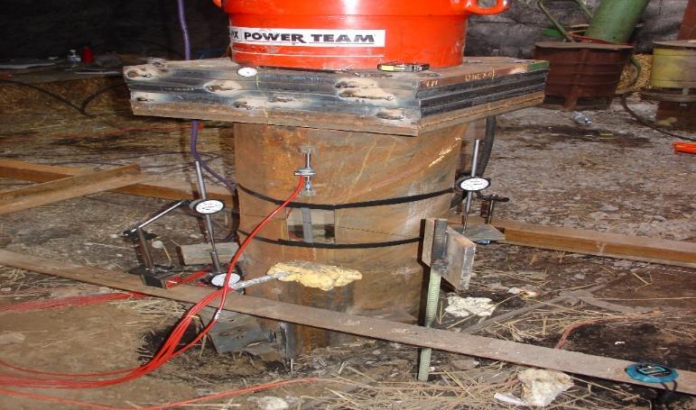
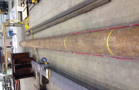
31 Schematics of Load Test Piles Pile Load Test Site Closed-ended pipe pile Pile base at 57 feet Pile Diameter = 14 inches Site Investigation 4 SPT borings with soil sampling 6 CPT tests Piezometer 1 2 f t C T C 1 2 f t C T Piezomete C r C2 2 fts2 C1 S1 2 ft Main Test Pile (MP1) C4 S3 C6 2 ft C7 6 ft CTC C5 4ft Main Test Pile (MP2) S4 6 ft CTC

32 SR 49 Load Test
33 Soil and Pile Information K 0 : 0.45 for loose sand (D R < 35%), 0.4 for medium dense to dense sand (D R 35%) Ground water table depth: 3.3 ft Closed-ended pipe pile 14 inches, 0.5 inch thick Pile length: 65.3 ft Embedded depth: 57.1 ft
34 CPT Data 0.0 highly organic soil clayey sand sandy clay clayey sand sandy clay clayey sand silty clay clayey silt silty clay Depth (m) Depth (M) Q t (MPa) C7 C Depth (M) F s/q t (%) C7 C silty clay very stiff silt Pile base location silty clay 20 20
35 Field Test Data SPT CPT
36 Comparison of Load Capacities Q sl (kip) Q bult * (kip) Q ult (kip) Measured/SLT CAPWAP/DLT Purdue method (SPT) Purdue method (CPT) DRIVEN * Not accounting for residual loads ** Load at settlement of 10% of pile diameter
37 Case Study SR 9 in Lagrange County (Pipe) SR 49 in Jasper County (Pipe) SR 49 in Jasper County (H) SR 55 in Lake County (H) US 31 in Marshall County (Pipe) /19/2015
38 Soil and Pile Information K 0 : 0.45 for loose sand (D R < 35%), 0.4 for medium dense to dense sand (D R 35%) Ground water table depth: 3.3 ft H pile: HP Embedded depth: 57.1 ft
39 Field Test Data CPT SPT
40 Comparison of Load Capacities Q sl (kip) Q bult * (kip) Q ult (kip) Measured/SLT CAPWAP/DLT Purdue method (CPT) DRIVEN *Load at settlement of 10% of pile diameter
41 Case Study SR 9 in Lagrange County (Pipe) SR 49 in Jasper County (Pipe) SR 49 in Jasper County (H) SR 55 in Lake County (H) US 31 in Marshall County (Pipe) /19/2015


42 Field Test Data CPT-1 CPT-2 3/19/
43 Soil and Pile Information Sand - 0 to 37 ft (N60 ~ 10-20) Silty Clay - 37 to 41 ft (N60 ~ 7-9) Sand - 41 to 45 ft (N60 ~ 20-30) Silty Clay - 45 to 66 ft (N60 ~ 8-9) Sand - 66 to 73 ft (N60 ~ 20-40) Silty Clay - 73 to 76 ft (N60 ~ 20) H-Pile 12x53 Embedment Depth 69.1 feet
44 Comparison of Load Capacities Method Q SL (kip) Q bult (kip) Q ult (kip) DLT/CAPWAP Purdue (CPT) DRIVEN
45 Case Study SR 9 in Lagrange County (Pipe) SR 49 in Jasper County (Pipe) SR 49 in Jasper County (H) SR 55 in Lake County (H) US 31 in Marshall County (Pipe)
46 Soil and Pile Information Layer number Elevation (lft) Soil Total unit weight (lb/ft3) Moisture content (%) Brown, moist, stiff to very stiff loam Brown, moist, medium dense sandy loam Brown, moist, dense sandy loam Gray, moist, very stiff loam Gray, moist, medium dense to very dense sandy loam Gray, moist, hard loam Pipe Pile 14 inch, inch thick Embedment Depth 51.2 feet

")
47 Static Load Test (June 25 th, 2014)
48 Field Test Data 0 CPT Cone resistance (tsf) SPT 10 CP T1 Depth (ft) CPT data
49 Comparison of Load Capacities Method Q sl (kip) Q bult* (kip) Q ult (kip) Measured Measured corrected by residual load DLT/CAPWAP Purdue (SPT with capping) Purdue (SPT without capping) Purdue method (CPT) DRIVEN * Load at settlement of 10% of pile diameter
50 Reference Research Papers Paik, K., Salgado, R., Lee, J., and Kim, B. (2003). Behavior of Openand Closed-Ended Piles Driven into Sands. Journal of Geotechnical and Geoenvironmental Engineering, 129(4), Assessment of Axially Loaded Pile Dynamic Design Methods and Review of INDOT Axially Loaded Pile Design Procedure, JTRP Research SPR-2856 Report Number: FHWA/IN/JTRP-2008/6 Kim, D., Bica, A. V., Salgado, R., Prezzi, M., & Lee, W. (2009). Load testing of a closed-ended pipe pile driven in multilayered soil. Journal of Geotechnical and Geoenvironmental Engineering, 135(4), Bica, Prezzi, Seo, Salgado and Kim (2012). Instrumentation and axial load testing of displacement piles Proceedings of the Institution of Civil Engineers, Paper Use of Pile Driving Analysis For Assessment of Axial Load Capacity of Piles, JTRP Research - SPR Report Number: FHWA/IN/JTRP-2012/11
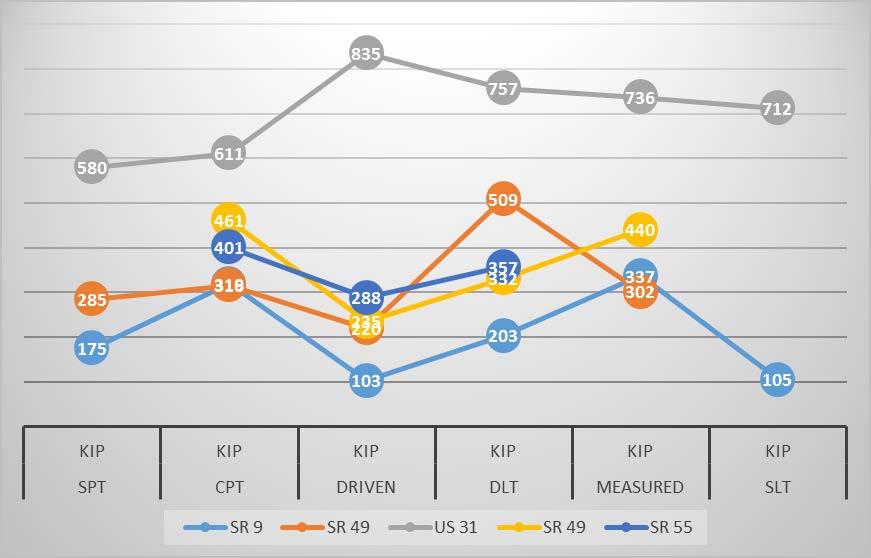
51 Comparison of Data

52 Comparison of CPT, Driven & DLT
53 Conclusions: Since, designs are based on Limit states, design of piles should also be based on servicibility limit states, i.e. settlement. The most predominant and most reliable method of pile design shall be the CPT Design Method. More number of Static Load Tests needs to be performed. Measured capacities were based on Chin Method. However, in many cases failure could be extrapolated.
54 INDOT Pile Costs 2009 to 2014 Indiana Standard Spec. Method of Pile Driving (a) (Gates) (b) (DLT/ CAPWAP) Totals Plan Contract Length (lft) Paid Pile Length (lft) 246, ,100 1,241, , ,873 1,154,517 Pile Lengths underrun/overrun (lft) (29,408) (57,227) (86,635) Pile Lengths underrun/overrun % (13.6%) (6.1%) (7.5%) Cost Paid to Contractor $ 11,653,634 $ 46,178,800 $ 57,832,434 Average Unit Cost (per lft) $ $ $ 50.09
55 Conclusions The use of pile dynamic formula (PDF) (a) has economic drawbacks: Factored load carrying capacity of PDF pile is 21% less than a DLT pile. For the same factored load pile lengths for PDF piles will be greater than DLT piles by 10 to 20%. Pile support cost per kip of structure load is 39% higher than a DLT pile. Based on past six years data, on an average per linear feet in ground cost of PDF piles is 9.2% more than the DLT piles. On an average, DLT capacity is less than Davisson Offset limit Capacity.
56 Conclusions (Contd.) DLT does a better site coverage, hence minimizes variability and overruns and underruns. The use of DLT piles should be increased for: All Piles designed for side friction Piles driven in to soft shale's There is a lesser risk in DLT piles than with Static Load test pile. Based on past six years data, on an average per linear feet in ground cost of PDF piles is 9.2% more than the DLT piles.
57 Thank you! 57
58 58 Dynamic formula [1] Nominal driving resistance 3/19/2015 R = 6.7 Elog(10 N) 445 ndr o o o o R ndr = nominal driving resistance (kn) E = manufacturer s rated energy (J) at the field observed ram stroke and not reduced for efficiency Log(10N) = logarithm to the base 10 of the quantity 10 multiplied by N N = number of hammer blows per 25mm at final penetration [1] INDOT Standard Specifications 2012.
59 59 Traditional Pile Driving Formulas 3/19/2015
60 ICP-05 [1] 3/19/ Unit base resistance (q b,ult ) for closed-ended pipe piles o In sandy soils [ ] q, = 1 0.5log( B/ B ) q b ult CPT c B = pile diameter B CPT = m o In clays q q = 0.8q b, ult cb, avg = 1.3q b, ult cb, avg Undrained loading Drained loading q cb,avg = averaged q c over a depth of 1.5B above and below the pile base level [1] Richard Jardine, Fiona Chow, Robert Overy and Jamie Standing. (2005), ICP Design Methods for Driven Piles in Sands and Clays", Published by Thomas Telford Publishing, Thomas Telford Ltd, 1 Heron Quay, London E14 4JD.
61 61 ICP-05 [1] Unit shaft resistance (q sl ) for closed-ended pipe piles o In sandy soils q = ( σ + σ ) tanδ sl rc rd cv σ v0 h 0.029qc max,8 p A R σ rc = σ = 2 G r/ R rd 6 2 ( σ ) ( σ ) G = q q p q p c c A v0 c A v0 R = pile radius r = 0.02mm for lightly rusted steel piles δδ cccc = interface friction angle (0.9ϕ c ) 1 3/19/2015 Pile length = h + z z h [1] Richard Jardine, Fiona Chow, Robert Overy and Jamie Standing. (2005), ICP Design Methods for Driven Piles in Sands and Clays", Published by Thomas Telford Publishing, Thomas Telford Ltd, 1 Heron Quay, London E14 4JD.
62 62 ICP-05 [1] Unit shaft resistance (q sl ) for closed-ended pipe piles o In clays Pile length = h + z 3/19/2015 q = 0.8K σ tanδ sl c v0 cv h c = vy max,8 K OCR I OCR R I = log S vy 10 t z R = pile radius S t = Sensitivity of clay δδ cccc = interface friction angle (0.9ϕ c ) h [1] Richard Jardine, Fiona Chow, Robert Overy and Jamie Standing. (2005), ICP Design Methods for Driven Piles in Sands and Clays", Published by Thomas Telford Publishing, Thomas Telford Ltd, 1 Heron Quay, London E14 4JD.
63 63 NGI-05 [1] 3/19/2015 Unit base resistance (q b,ult ) for closed-ended pipe piles o In sandy soils q 0.8q = q 1 0.4ln 22 cb, avg b, ult 2 cb, avg ( σ p ) vb A q cb,avg = the representative cone resistance at the pile base level [1] Clausen, C. J. F., P. M. Aas, and K. Karlsrud. (2005) "Bearing capacity of driven piles in sand, the NGI approach." Proceedings of Proceedings of International Symposium. on Frontiers in Offshore Geotechnics, Perth
64 64 NGI-05 [1] Unit shaft resistance (q sl ) for closed-ended pipe piles 3/19/2015 o In sandy soils 0.25 z σ v qsl = max pa Fq F,0.1 c tipfload Fmat σ v zbase p A F F F F q c tip load mat q c = ln ( σ v0 pa) = 1.6 = 1.3 = z base z [1] Clausen, C. J. F., P. M. Aas, and K. Karlsrud. (2005) "Bearing capacity of driven piles in sand, the NGI approach." Proceedings of Proceedings of International Symposium. on Frontiers in Offshore Geotechnics, Perth
65 65 NGI-05 [1] Unit shaft resistance (q sl ) for closed-ended pipe piles 3/19/2015 o In clays q α q sl NC NC = 0.32(PI 10) α = 0.5( s / σ ) F q u sl u tip u = ( s / σ ) tip u v sl = α u s = αsf = αs v 0.5 ( ) s / σ < 0.25 u v NC 0.20 α 1.0 ( ) s / σ > 1.0 u v F tip ( s σ ) 0.25 < / < 1.0 u v NC clay OC clay α is determined by a linear interpolation [1] Karlsrud, K., Clausen, C.J.F. and Aas, P.M. (2005), "Bearing capacity of driven piles in clay, the NGI approach", Proc., 1st Int. Symposium on Frontiers in Offshore Geotechnics, Balkema, Perth, Ausralia,
66 66 UWA-05 [1] 3/19/2015 Unit base resistance (q b,ult ) for closed-ended pipe piles o In sandy soils q = 0.6q b, ult cb, avg q cb,avg = the representative cone resistance at the pile base level [1] Lehane, B. M., Schneider, J. A., & Xu, X. (2005). The UWA-05 method for prediction of axial capacity of driven piles in sand. Frontiers in Offshore Geotechnics: ISFOG,
67 67 UWA-05 [1] Unit shaft resistance (q sl ) for closed-ended pipe piles o In sandy soils q f 4G r = σ + tanδ f D sl rc cv c h σ rc = 0.03qc max, 2 D qc / p A G/ qc = ( σ v0 / pa) r = 0.02mm f / f c = 1 for compression and 0.75 for tension δδ cccc = interface friction angle (0.9ϕ c ) 3/19/2015 Pile length = h + z z h [1] Lehane, B. M., Schneider, J. A., & Xu, X. (2005). The UWA-05 method for prediction of axial capacity of driven piles in sand. Frontiers in Offshore Geotechnics: ISFOG,
Assessment of Calculation Procedures for Piles in Clay based on Static Loading Tests Anders Hust Augustesen
 Assessment of Calculation Procedures for Piles in Clay based on Static Loading Tests By Anders Hust Augustesen 1 Agenda Presentation of calculation procedures Basis for the evaluation of the calculation
Lesson 25. Static Pile Load Testing, O-cell, and Statnamic. Reference Manual Chapter 18
 Lesson 25 Static Pile Load Testing, O-cell, and Statnamic Reference Manual Chapter 18 STATIC LOAD TESTING Most accurate method to determine static pile capacity Perform at design or construction stage
INTRODUCTION TO STATIC ANALYSIS PDPI 2013
 INTRODUCTION TO STATIC ANALYSIS PDPI 2013 What is Pile Capacity? When we load a pile until IT Fails what is IT Strength Considerations Two Failure Modes 1. Pile structural failure controlled by allowable
Civil Engineering, Surveying and Environmental Consulting WASP0059.ltr.JLS.Mich Ave Bridge Geotech.docx
 2365 Haggerty Road South * Canton, Michigan 48188 P: 734-397-3100 * F: 734-397-3131 * www.manniksmithgroup.com August 29, 2012 Mr. Richard Kent Washtenaw County Parks and Recreation Commission 2330 Platt
Implementation of Pile Setup in the LRFD Design of Driven Piles in Louisiana
 Implementation of Pile Setup in the LRFD Design of Driven Piles in Louisiana Md. Nafiul Haque (Ph.D. Candidate) Murad Y. Abu-Farsakh, Ph.D., P.E. March 1, 2016 Louisiana Transportation Conference OUTLINE
Cone Penetration Test (CPT) Interpretation
 Interpretation") Cone Penetration Test (CPT) Interpretation Gregg uses a proprietary CPT interpretation and plotting software. The software takes the CPT data and performs basic interpretation in terms of soil behavior
Cone Penetration Test (CPT) Interpretation Gregg uses a proprietary CPT interpretation and plotting software. The software takes the CPT data and performs basic interpretation in terms of soil behavior
In-class Exercise. Problem: Select load factors for the Strength I and Service I Limit States for the. Loading Diagram for Student Exercise
 In-class Exercise Problem: Select load factors for the Strength I and Service I Limit States for the problem illustrated below. Loading Diagram for Student Exercise For this exercise, complete the following
Use of Ultra-High Performance Concrete in Geotechnical and Substructure Applications
 Use of Ultra-High Performance Concrete in Geotechnical and Substructure Applications i PI: Muhannad Suleiman Co-PI: Sri Sritharan Graduate Research Assistant: Thomas L. Vande Voort January 13, 29 IOWA
LRFD Calibration of Axially-Loaded Concrete Piles Driven into Louisiana Soils
 LRFD Calibration of Axially-Loaded Concrete Piles Driven into Louisiana Soils Louisiana Transportation Conference February 10, 2009 Sungmin Sean Yoon, Ph. D., P.E. (Presenter) Murad Abu-Farsakh, Ph. D.,
PILE SETUP LA-1 EXPERIENCE. Ching-Nien Tsai, P.E.
 PILE SETUP LA-1 EXPERIENCE Ching-Nien Tsai, P.E. Bayou Lafourche Mississippi River GEOTECHNICAL INVESTIGATION PROGRAM 102 CPT soundings Depths from 100 feet to 200 feet 118 borings Depths from
CPT Data Interpretation Theory Manual
 CPT Data Interpretation Theory Manual 2016 Rocscience Inc. Table of Contents 1 Introduction... 3 2 Soil Parameter Interpretation... 5 3 Soil Profiling... 11 3.1 Non-Normalized SBT Charts... 11 3.2 Normalized
Penetration Rate Effects on Cone Resistance: Insights From Calibration Chamber and Field Testing
 Penetration Rate Effects on Cone Resistance: Insights From Calibration Chamber and Field Testing R. Salgado, M. Prezzi Abstract. Cone penetration in mixed or intermediate soils (soils containing mixtures
USE OF CPT/CPTU FOR SOLUTION OF
 USE OF CPT/CPTU FOR SOLUTION OF PRACTICAL PROBLEMS Tom Lunne, NGI USE OF CPT/CPTU FOR SULUTION OF PRACTICAL PROBLEMS Indirect design method: Interprete CPT/CPTU results to arrive at soil design parameters
CPT Guide 5 th Edition. CPT Applications - Deep Foundations. Gregg Drilling & Testing, Inc. Dr. Peter K. Robertson Webinar # /2/2013
 Gregg Drilling & Testing, Inc. Site Investigation Experts CPT Applications - Deep Foundations Dr. Peter K. Robertson Webinar #6 2013 CPT Guide 5 th Edition Robertson & Cabal (Robertson) 5 th Edition 2012
LRFD Application in Driven Piles (Recent Development in Pavement & Geotech at LTRC)
") LRFD Application in Driven Piles (Recent Development in Pavement & Geotech at LTRC) 2007 Louisiana Transportation Engineering Conference February 12, 2007 Sungmin Sean Yoon, Ph. D., P.E. and Murad Abu-Farsakh,
LRFD Application in Driven Piles (Recent Development in Pavement & Geotech at LTRC) 2007 Louisiana Transportation Engineering Conference February 12, 2007 Sungmin Sean Yoon, Ph. D., P.E. and Murad Abu-Farsakh,
Implementation of Laterally Loaded Piles in Multi-Layer Soils
 Implementation of Laterally Loaded Piles in Multi-Layer Soils JTRP SPR- 3261 Final SAC meeting SAC members Mir Zaheer and Keith Hoernschemeyer Purdue University Introduction Analysis developed for the
Additional Pile Design Considerations
 Additional Pile Design Considerations PDCA 2015 Professor Driven Pile Institute Patrick Hannigan GRL Engineers, Inc. What Are Additional Pile Design Considerations? Time Dependent Soil Strength Changes
CPT: Geopractica Contracting (Pty) Ltd Total depth: m, Date:
 Ltd Total depth: m, Date:") The plot below presents the cross correlation coeficient between the raw qc and fs values (as measured on the field). X axes presents the lag distance (one lag is the distance between two sucessive CPT
The plot below presents the cross correlation coeficient between the raw qc and fs values (as measured on the field). X axes presents the lag distance (one lag is the distance between two sucessive CPT
A presentation of UniPile software for calculation of Capacity, Drag Force, Downdrag, and Settlement for Piles and Piled Foundations
 528 River Road, Ottawa, Ontario, Canada, K1V 1E9 E: info@unisoftgs.com A presentation of UniPile software for calculation of Capacity, Drag Force, Downdrag, and Settlement for Piles and Piled Foundations
Axially Loaded Piles
 Axially Loaded Piles 1 t- Curve Method using Finite Element Analysis The stress-strain relationship for an axially loaded pile can be described through three loading mechanisms: axial deformation in the
Chapter (11) Pile Foundations
 Pile Foundations") Chapter (11) Introduction Piles are structural members that are made of steel, concrete, or timber. They are used to build pile foundations (classified as deep foundations) which cost more than shallow
Chapter (11) Introduction Piles are structural members that are made of steel, concrete, or timber. They are used to build pile foundations (classified as deep foundations) which cost more than shallow
Chapter 12 Subsurface Exploration
 Page 12 1 Chapter 12 Subsurface Exploration 1. The process of identifying the layers of deposits that underlie a proposed structure and their physical characteristics is generally referred to as (a) subsurface
INCREASE IN PILE CAPACITY WITH TIME IN MISSOURI RIVER ALLUVIUM
 INCREASE IN PILE CAPACITY WITH TIME IN MISSOURI RIVER ALLUVIUM Paul J. Axtell Jacob W. Owen Scott D. Vollink U.S. Army Corps of Engineers U.S. Army Corps of Engineers U.S. Army Corps of Engineers Kansas
CHAPTER 7 ANALYSES OF THE AXIAL LOAD TESTS AT THE ROUTE 351 BRIDGE
 CHAPTER 7 ANALYSES OF THE AXIAL LOAD TESTS AT THE ROUTE 351 BRIDGE 7.1 INTRODUCTION In this chapter, calculations using methods commonly employed in practice are presented for the pile axial load capacity,
ASD and LRFD Methods Codes and Economics of Dynamic Testing ASTM D4945
 ASD and LRFD Methods Codes and Economics of Dynamic Testing ASTM D4945 Load Testing. Static Load Testing ASTM D1143 Deadload Testing React. Piles/Anchors Static Load Tests are the standard Costly: Need
The Bearing Capacity of Soils. Dr Omar Al Hattamleh
 The Bearing Capacity of Soils Dr Omar Al Hattamleh Example of Bearing Capacity Failure Omar Play the move of bearing Capacity failure The Philippine one Transcona Grain Silos Failure - Canada The Bearing
Class Principles of Foundation Engineering CEE430/530
 Class Principles of Foundation Engineering CEE430/530 1-1 General Information Lecturer: Scott A. Barnhill, P.E. Lecture Time: Thursday, 7:10 pm to 9:50 pm Classroom: Kaufmann, Room 224 Office Hour: I have
CPT Pore Water Pressure Correlations with PDA to Identify Pile Drivability Problem
 CPT Pore Water Pressure Correlations with PDA to Identify Pile Drivability Problem Fauzi Jarushi, Paul Cosentino, Edward Kalajian, Hadeel Dekhn Abstract At certain depths during large diameter displacement
Chapter 7 GEOMECHANICS
 Chapter 7 Final SCDOT GEOTECHNICAL DESIGN MANUAL August 2008 Table of Contents Section Page 7.1 Introduction...7-1 7.2 Geotechnical Design Approach...7-1 7.3 Geotechnical Engineering Quality Assurance...7-2
Calibration of Resistance Factors for Drilled Shafts for the 2010 FHWA Design Method
 Calibration of Resistance Factors for Drilled Shafts for the 21 FHWA Design Method Murad Y. Abu-Farsakh, Ph.D., P.E. Qiming Chen, Ph.D., P.E. Md Nafiul Haque, MS Feb 2, 213 213 Louisiana Transportation
Engineeringmanuals. Part2
 Engineeringmanuals Part2 Engineering manuals for GEO5 programs Part 2 Chapter 1-12, refer to Engineering Manual Part 1 Chapter 13. Pile Foundations Introduction... 2 Chapter 14. Analysis of vertical load-bearing
Soil property-based methods for design of nondisplacement piles
 Soil property-based methods for design of nondisplacement piles R. Salgado Professor, School of Civil Engineering, Purdue University, West Lafayette, Indiana, USA M. Prezzi Professor, School of Civil Engineering,
Jose Brito, Cenor, Portugal
 Jose Brito, Cenor, Portugal Carsten S. Sorensen, COWI, Denmark In this example it is asked to design a square pad foundation according to Eurocode 7. The aim is the evaluation of the foundation width with
Comparisons of rapid load test, dynamic load test and static load test on driven piles
 Comparisons of rapid load test, dynamic load test and static load test on driven piles Bamrungwong, C., Chaisukhang, J. & Janmonta, K. Department of Rural Roads, Thailand Kitiyodom, P. Geotechnical & Foundation
Discussion: behaviour of jacked and driven piles in sandy soil
 Title Discussion: behaviour of jacked and driven piles in sandy soil Author(s) Yang, J; Tham, LG; Lee, PKK; Chan, ST; Yu, F Citation Géotechnique, 27, v. 7 n., p. 47-478 Issued Date 27 URL http://hdl.handle.net/1722/7161
S E C T I O N 1 2 P R O D U C T S E L E C T I O N G U I D E - H E L I C A L S C R E W P I L E F O U N D A T I O N S
 1. P R O D U C T S E L E C T I O N G U I D E - H E L I C A L S C R E W P I L E F O U N D A T I O N S Helical foundation pile includes a lead and extension(s). The lead section is made of a central steel
SHEAR STRENGTH OF SOIL
 Soil Failure Criteria SHEAR STRENGTH OF SOIL Knowledge about the shear strength of soil important for the analysis of: Bearing capacity of foundations, Slope stability, Lateral pressure on retaining structures,
Deep Foundations 2. Load Capacity of a Single Pile
 Deep Foundations 2 Load Capacity of a Single Pile All calculations of pile capacity are approximate because it is almost impossible to account for the variability of soil types and the differences in the
CHAPTER 8 CALCULATION THEORY
 CHAPTER 8 CALCULATION THEORY. Volume 2 CHAPTER 8 CALCULATION THEORY Detailed in this chapter: the theories behind the program the equations and methods that are use to perform the analyses. CONTENTS CHAPTER
Numerical modelling of tension piles
 Numerical modelling of tension piles S. van Baars Ministry of Public Works, Utrecht, Netherlands W.J. van Niekerk Ballast Nedam Engineering, Amstelveen, Netherlands Keywords: tension piles, shaft friction,
8.1. What is meant by the shear strength of soils? Solution 8.1 Shear strength of a soil is its internal resistance to shearing stresses.
 8.1. What is meant by the shear strength of soils? Solution 8.1 Shear strength of a soil is its internal resistance to shearing stresses. 8.2. Some soils show a peak shear strength. Why and what type(s)
Table 3. Empirical Coefficients for BS 8002 equation. A (degrees) Rounded Sub-angular. 2 Angular. B (degrees) Uniform Moderate grading.
 Rounded Sub-angular. 2 Angular. B (degrees) Uniform Moderate grading.") Hatanaka and Uchida (1996); ' 20N 20 12N 20 ' 45 A lower bound for the above equation is given as; 12N 15 ' 45 Table 3. Empirical Coefficients for BS 8002 equation A Angularity 1) A (degrees) Rounded 0
Hatanaka and Uchida (1996); ' 20N 20 12N 20 ' 45 A lower bound for the above equation is given as; 12N 15 ' 45 Table 3. Empirical Coefficients for BS 8002 equation A Angularity 1) A (degrees) Rounded 0
Centrifuge investigation of the axial cyclic behaviour of a single pile used for the foundation of a jacket type offshore wind turbine
 Centrifuge investigation of the axial cyclic behaviour of a single pile used for the foundation of a jacket type offshore wind turbine Mathieu Blanc, Luc Thorel, Rocio Isorna, Christophe Dano, Panagiotis
Ohio Department of Transportation. Development of CPT Driven Pile Direct Design Methodology for ODOT
 Ohio Department of Transportation John R. Kasich, Governor Jerry Wray, Director Development of CPT Driven Pile Direct Design Methodology for ODOT Alexander B.C. Dettloff, P.E. Foundations Engineer Division
BACKGROUND AND INTRODUCTION
 WAVE MECHANICS As applied to pile testing 1 BACKGROUND AND INTRODUCTION Wave Mechanics 2 1 HISTORIC TOOLS AND MATERIALS Timber piles Drop Hammers 10 Days for the Romans to build the bridge over the Rhine
The San Jacinto Monument Case History
 Picture obtained from http://www.laanba.net/photoblog/ January05/sanjacinto.jpg Jean-Louis Briaud Texas A&M University The San Jacinto Monument Case History 1 2 CREDITS Phillip King Fugro Briaud J.-L.,
Drilled Shaft Foundations in Limestone. Dan Brown, P.E., Ph.D. Dan Brown and Associates
 Drilled Shaft Foundations in Limestone Dan Brown, P.E., Ph.D. Dan Brown and Associates Foundation Engineering How we teach our students Fundamental understanding of soil and rock behavior (good!) Focus
Maximum Envelope of Lateral Resistance through Dynamic Increasing Energy Test in Piles
 Maximum Envelope of Lateral Resistance through Dynamic Increasing Energy Test in Piles R.M. Valverde, F. Massad Abstract. The traditional dynamic load test, based on the one-dimensional wave propagation
Congreso Internacional de Fundaciones Profundas de Bolivia Santa Cruz, Bolivia, 12 al 15 de Mayo de 2015 Day 1: Software Demonstrations
 Applications of Stress Wave Theory to Deep Foundations with an Emphasis on The Wave Equation (GRLWEAP) Congreso Internacional de Fundaciones Profundas de Bolivia Santa Cruz, Bolivia, 12 al 15 de Mayo de
A Comparative Study on Bearing Capacity of Shallow Foundations in Sand from N and /
 DOI 10.1007/s40030-017-0246-7 ORIGINAL CONTRIBUTION A Comparative Study on Bearing Capacity of Shallow Foundations in Sand from N and / V. A. Sakleshpur 1 C. N. V. Satyanarayana Reddy 1 Received: 9 January
Theory of Shear Strength
 SKAA 1713 SOIL MECHANICS Theory of Shear Strength Prepared by, Dr. Hetty 1 SOIL STRENGTH DEFINITION Shear strength of a soil is the maximum internal resistance to applied shearing forces The maximum or
Soil type identification and fines content estimation using the Screw Driving Sounding (SDS) data
 data") Mirjafari, S.Y. & Orense, R.P. & Suemasa, N. () Proc. th NZGS Geotechnical Symposium. Eds. GJ Alexander & CY Chin, Napier Soil type identification and fines content estimation using the Screw Driving Sounding
Mirjafari, S.Y. & Orense, R.P. & Suemasa, N. () Proc. th NZGS Geotechnical Symposium. Eds. GJ Alexander & CY Chin, Napier Soil type identification and fines content estimation using the Screw Driving Sounding
This document downloaded from vulcanhammer.net vulcanhammer.info Chet Aero Marine
 This document downloaded from vulcanhammer.net vulcanhammer.info Chet Aero Marine Don t forget to visit our companion site http://www.vulcanhammer.org Use subject to the terms and conditions of the respective
The CPT in unsaturated soils
 The CPT in unsaturated soils Associate Professor Adrian Russell (UNSW) Mr David Reid (Golder Associates) Prof Nasser Khalili (UNSW) Dr Mohammad Pournaghiazar (UNSW) Dr Hongwei Yang (Uni of Hong Kong) Outline
 Project: ITHACA-TOMPKINS REGIONAL AIRPORT EXPANSION Project Location: ITHACA, NY Project Number: 218-34 Key to Soil Symbols and Terms TERMS DESCRIBING CONSISTENCY OR CONDITION COARSE-GRAINED SOILS (major
Laboratory Testing Total & Effective Stress Analysis
 SKAA 1713 SOIL MECHANICS Laboratory Testing Total & Effective Stress Analysis Prepared by: Dr. Hetty Mohr Coulomb failure criterion with Mohr circle of stress 2 ' 2 ' ' ' 3 ' 1 ' 3 ' 1 Cot Sin c ' ' 2
Chapter 5 Shear Strength of Soil
 Page 5 Chapter 5 Shear Strength of Soil. The internal resistance per unit area that the soil mass can offer to resist failure and sliding along any plane inside it is called (a) strength (b) shear strength
NEW DOWN-HOLE PENETROMETER (DHP-CIGMAT) FOR CONSTRUCTION APPLICATIONS
 FOR CONSTRUCTION APPLICATIONS") NEW DOWN-HOLE PENETROMETER (DHP-CIGMAT) FOR CONSTRUCTION APPLICATIONS 1 2 C. Vipulanandan 1, Ph.D., M. ASCE and Omer F. Usluogullari 2 Chairman, Professor, Director of Center for Innovative Grouting Materials
NEW DOWN-HOLE PENETROMETER (DHP-CIGMAT) FOR CONSTRUCTION APPLICATIONS 1 2 C. Vipulanandan 1, Ph.D., M. ASCE and Omer F. Usluogullari 2 Chairman, Professor, Director of Center for Innovative Grouting Materials
Cone Penetration Test Design Guide for State Geotechnical Engineers
 Cone Penetration Test Design Guide for State Geotechnical Engineers Author: David Saftner Report Number: 2018-32 Date Published: November 2018 Minnesota Department of Transportation Research Services &
ANALYSIS OF LATERALLY LOADED FIXED HEADED SINGLE FLOATING PILE IN MULTILAYERED SOIL USING BEF APPROACH
 INDIAN GEOTECHNICAL SOCIETY, KOLKATA CHAPTER GEOTECHNICS FOR INFRASTRUCTURE DEVELOPMENT KOLKATA 11 th 12 th March 2016, Kolkata, West Bengal, India ANALYSIS OF LATERALLY LOADED FIXED HEADED SINGLE FLOATING
B-1 BORE LOCATION PLAN. EXHIBIT Drawn By: 115G BROOKS VETERINARY CLINIC CITY BASE LANDING AND GOLIAD ROAD SAN ANTONIO, TEXAS.
 N B-1 SYMBOLS: Exploratory Boring Location Project Mngr: BORE LOCATION PLAN Project No. GK EXHIBIT Drawn By: 115G1063.02 GK Scale: Checked By: 1045 Central Parkway North, Suite 103 San Antonio, Texas 78232
WIND TUNNEL TESTING GEOTECHNICAL STUDY
 WIND TUNNEL TESTING Wind tunnel testing was conducted by the Boundary Layer Wind Tunnel Laboratory (BLWTL) at the University of Western Ontario (UWO) to develop wind load time histories for the chimney.
EN Eurocode 7. Section 3 Geotechnical Data Section 6 Spread Foundations. Trevor L.L. Orr Trinity College Dublin Ireland.
 EN 1997 1: Sections 3 and 6 Your logo Brussels, 18-20 February 2008 Dissemination of information workshop 1 EN 1997-1 Eurocode 7 Section 3 Geotechnical Data Section 6 Spread Foundations Trevor L.L. Orr
Conventional Field Testing & Issues (SPT, CPT, DCPT, Geophysical methods)
") Conventional Field Testing & Issues (SPT, CPT, DCPT, Geophysical methods) Ajanta Sachan Assistant Professor Civil Engineering IIT Gandhinagar Conventional Field Testing 1 Field Test: In-situ shear strength
Conventional Field Testing & Issues (SPT, CPT, DCPT, Geophysical methods) Ajanta Sachan Assistant Professor Civil Engineering IIT Gandhinagar Conventional Field Testing 1 Field Test: In-situ shear strength
Cone Penetration Testing in Geotechnical Practice
 Cone Penetration Testing in Geotechnical Practice Table Of Contents: LIST OF CONTENTS v (4) PREFACE ix (2) ACKNOWLEDGEMENTS xi (1) SYMBOL LIST xii (4) CONVERSION FACTORS xvi (6) GLOSSARY xxii 1. INTRODUCTION
Safety Concepts and Calibration of Partial Factors in European and North American Codes of Practice
 Safety Concepts and Calibration of Partial Factors in European and North American Codes of Practice The Dutch approach on Geotechnical Design by Eurocode 7 Adriaan van Seters Hein Jansen Fugro GeoServices
Geotechnical Engineering Report
 Geotechnical Engineering Report Turner Turnpike Widening Bridge B Bridge Crossing: South 257 th West Avenue Creek County, Oklahoma June 1, 2016 Terracon Project No. 04155197 Prepared for: Garver, LLC Tulsa,
CPT: _CPTU1. GEOTEA S.R.L. Via della Tecnica 57/A San Lazzaro di Savena (BO)
") 468 - San Lazzaro di Savena (BO) +39.51.655377 Project: CPeT-IT v.1.7.6.4 - CPTU data presentation & interpretation software - Report created on: 5/1/16, 11.51.3 Project file: \\Server\server\GEOTEA\LAVORI\16\16.8_FA.TA.
468 - San Lazzaro di Savena (BO) +39.51.655377 Project: CPeT-IT v.1.7.6.4 - CPTU data presentation & interpretation software - Report created on: 5/1/16, 11.51.3 Project file: \\Server\server\GEOTEA\LAVORI\16\16.8_FA.TA.
Soil Behaviour Type from the CPT: an update
 Soil Behaviour Type from the CPT: an update P.K. Robertson Gregg Drilling & Testing Inc., Signal Hill, California, USA ABSTRACT: One of the most common applications of CPT results is to evaluate soil type
DRILLED DISPLACMENT PILE PERFORMANCE IN COASTAL PLAIN AND RESIDUAL SOILS
 DRILLED DISPLACMENT PILE PERFORMANCE IN COASTAL PLAIN AND RESIDUAL SOILS Presented by: W. Morgan NeSmith, P.E. Berkel & Company Contractors Inc. 770.941.5100 mnesmith@berkelapg.com SC Engineering Conference
Cavity Expansion Methods in Geomechanics
 Cavity Expansion Methods in Geomechanics by Hai-Sui Yu School of Civil Engineering, University of Nottingham, U. K. KLUWER ACADEMIC PUBLISHERS DORDRECHT / BOSTON / LONDON TABLE OF CONTENTS Foreword Preface
Recent developments in axial design of driven offshore piles. DGF Copenhagen April 1 st 2014
 Recent developments in axial design of driven offshore piles DGF Copenhagen April 1 st 2014 Richard Jardine Page 1 Themes: Changed API, ISO axial capacity recommendations for sands, including ICP-05 Research
Soil Mechanics Brief Review. Presented by: Gary L. Seider, P.E.
 Soil Mechanics Brief Review Presented by: Gary L. Seider, P.E. 1 BASIC ROCK TYPES Igneous Rock (e.g. granite, basalt) Rock formed in place by cooling from magma Generally very stiff/strong and often abrasive
FHWA/IN/JTRP-2008/5. Final Report. Dongwook Kim Rodrigo Salgado
 FHWA/IN/JTRP-2008/5 Final Report LIMIT STATES AND LOAD AND RESISTANCE DESIGN OF SLOPES AND RETAINING STRUCTURES Dongwook Kim Rodrigo Salgado January 2009 INDOT Research TECHNICAL Summary Technology Transfer
SHEAR STRENGTH OF SOIL
 SHEAR STRENGTH OF SOIL Necessity of studying Shear Strength of soils : Soil failure usually occurs in the form of shearing along internal surface within the soil. Shear Strength: Thus, structural strength
PERFORMANCE OF BITUMINOUS COATS IN REDUCING NEGATIVE SKIN
 PERFORMANCE OF BITUMINOUS COATS IN REDUCING NEGATIVE SKIN FRICTION Makarand G. Khare, PhD Research Scholar, Indian Institute of Technology Madras, Chennai, India Shailesh R. Gandhi, Professor, Indian Institute
Theory of Shear Strength
 MAJ 1013 ADVANCED SOIL MECHANICS Theory of Shear Strength Prepared by, Dr. Hetty 1 Strength of different materials Steel Concrete Soil Tensile strength Compressive strength Shear strength Complex behavior
Shear Strength of Soils
 Shear Strength of Soils STRESSES IN A SOIL ELEMENT t s v Analyze Effective Stresses (s ) Load carried by Soil t Where: s H t t s H s = t f = s v = s H = t = s v Stresses in a Soil Element after Figure
Boreholes. Implementation. Boring. Boreholes may be excavated by one of these methods: 1. Auger Boring 2. Wash Boring 3.
 Implementation Boreholes 1. Auger Boring 2. Wash Boring 3. Rotary Drilling Boring Boreholes may be excavated by one of these methods: 4. Percussion Drilling The right choice of method depends on: Ground
World Academy of Science, Engineering and Technology International Journal of Geotechnical and Geological Engineering Vol:11, No:9, S.
 Design and Construction Validation of Pile Performance through High Strain Pile Dynamic Tests for both Contiguous Flight Auger and Drilled Displacement Piles S. Pirrello Abstract Sydney s booming real
Chapter (5) Allowable Bearing Capacity and Settlement
 Allowable Bearing Capacity and Settlement") Chapter (5) Allowable Bearing Capacity and Settlement Introduction As we discussed previously in Chapter 3, foundations should be designed for both shear failure and allowable settlement. So the allowable
Chapter (5) Allowable Bearing Capacity and Settlement Introduction As we discussed previously in Chapter 3, foundations should be designed for both shear failure and allowable settlement. So the allowable
Geotechnical Engineering Report
 Geotechnical Engineering Report Turner Turnpike Widening Bridge D Bridge Crossing: South 209 th West Avenue Creek County, Oklahoma June 1, 2016 Terracon Project No. 04155197 Prepared for: Garver, LLC Tulsa,
Correlations between soil parameters and penetration testing results
 1 A 1 6 Correlations between soil parameters and penetration testing results Corrélation entre paramètres du sol et résultats de sondage J. FORMAZIN, Director, VEB SBK Wasserbau, KB Baugrund Berlin, Berlin,
 R-1 Conveyor Relocation Project Legend 0 500 1000 1500 ft. This map is a user generated static output from an Internet mapping site and is for general reference only. Data layers that appear on this map
Liquefaction Induced Negative Skin Friction from Blast-induced Liquefaction Tests with Auger-cast Piles
 6 th International Conference on Earthquake Geotechnical Engineering 1-4 November 2015 Christchurch, New Zealand Liquefaction Induced Negative Skin Friction from Blast-induced Liquefaction Tests with Auger-cast
Understanding Dynamic Pile Testing and Driveability
 008-015 understand dynamic 5/30/06 5:10 PM Page 8 Understanding Dynamic Pile Testing and Driveability... By: Engr. Dr Sam Ming Tuck MIEM, P.Eng INTRODUCTION Traditionally, piles are static load tested
Chapter (12) Instructor : Dr. Jehad Hamad
 Instructor : Dr. Jehad Hamad") Chapter (12) Instructor : Dr. Jehad Hamad 2017-2016 Chapter Outlines Shear strength in soils Direct shear test Unconfined Compression Test Tri-axial Test Shear Strength The strength of a material is the
Chapter (12) Instructor : Dr. Jehad Hamad 2017-2016 Chapter Outlines Shear strength in soils Direct shear test Unconfined Compression Test Tri-axial Test Shear Strength The strength of a material is the
Use of CPT for design, monitoring, and performance verification of compaction projects
 Cone Stress, q t (MPa) 2 3 Sleeve Friction (KPa) 2 4 Pore Pressure (KPa) 2 7, Friction Ratio (%) 2 3 4 Profile Mixed Y 2 2 2 2 CLAY 3 3 3 3 4 4 4 4 SAN D Use of CPT for design, monitoring, and performance
vulcanhammer.info the website about Vulcan Iron Works Inc. and the pile driving equipment it manufactured Terms and Conditions of Use:
 this document downloaded from vulcanhammer.info the website about Vulcan Iron Works Inc. and the pile driving equipment it manufactured Terms and Conditions of Use: All of the information, data and computer
Comparison of Static and Dynamic Pile Load Tests at Thi Vai International Port in Viet Nam
 Comparison of Static and Dynamic Pile Load Tests at Thi Vai International Port in Viet Nam Le Phan Ta, Ph.D student, Graduate School of Kanazawa University, Japan (HCMC University of Architecture, Viet
Geotechnical Engineering Report
 Geotechnical Engineering Report Turner Turnpike Widening Polecat Creek Bridge (Bridge A) June 1, 2016 Terracon Project No. 04155197 Prepared for: Garver, LLC Prepared by: Terracon Consultants, Inc. TABLE
June 9, R. D. Cook, P.Eng. Soils Engineer Special Services Western Region PUBLIC WORKS CANADA WESTERN REGION REPORT ON
 PUBLIC WORKS CANADA WESTERN REGION REPORT ON GEOTECHNICAL INVESTIGATION PROPOSED MARTIN RIVER BRIDGE MILE 306.7 MACKENZIE HIGHWAY Submitted by : R. D. Cook, P.Eng. Soils Engineer Special Services Western
Liquefaction and Foundations
 Liquefaction and Foundations Amit Prashant Indian Institute of Technology Gandhinagar Short Course on Seismic Design of Reinforced Concrete Buildings 26 30 November, 2012 What is Liquefaction? Liquefaction
STUDY OF THE BEHAVIOR OF PILE GROUPS IN LIQUEFIED SOILS
 STUDY OF THE BEHAVIOR OF PILE GROUPS IN LIQUEFIED SOILS Shin-Tower Wang 1, Luis Vasquez 2, and Lymon C. Reese 3, Honorary Member,, ASCE ABSTRACT : 1&2 President & Project Manager, Ensoft, Inc. Email: ensoft@ensoftinc.com
s u (mm) D r 1 0.1a D D r ) E p 5 Young s modulus of pile material (kn>mm 2 )
 D r 1 0.1a D D r ) E p 5 Young s modulus of pile material (kn>mm 2 )") 11.1 Pile Load Tests 585 Pile settlement may increase with load to a certain point, beyond which the load settlement curve becomes vertical. The load corresponding to the point where the curve of Q versus
11.1 Pile Load Tests 585 Pile settlement may increase with load to a certain point, beyond which the load settlement curve becomes vertical. The load corresponding to the point where the curve of Q versus
Neutral Plane Method for Drag Force of Deep Foundations and the AASHTO LRFD Bridge Design Specifications
 Neutral Plane Method for Drag Force of Deep Foundations and the AASHTO LRFD Bridge Design Specifications Timothy C. Siegel, P.E., G.E., D.GE Dan Brown and Associates, PC, Knoxville, Tennessee USA Rich
Geotechnical Recommendations for Proposed Additions to the Three Mile Creek Severe Weather Attenuation Tank Project
 TECHNICAL MEMORANDUM Geotechnical Recommendations for Proposed Additions to the Three Mile Creek Severe Weather Attenuation Tank Project PREPARED FOR: PREPARED BY: DATE: June 28, 218 PROJECT NUMBER: 697482
Reliability of Settlement Analysis for Shallow Foundations
 Geotechnical Engineering Research Laboratory University of Massachusetts Lowell, MA USA Reliability of Settlement Analysis for Shallow Foundations 14.533 ADVANCED FOUNDATION ENGINEERING Fall 2013 Samuel
Structure, Member Design - Geotechnics Piles XX
 E N G I N E E R S Consulting Engineers jxxx 1 Material Properties Characteristic strength of concrete, f cu ( 60N/mm 2 ; HSC ) 40 N/mm 2 OK Yield strength of longitudinal steel, f y 460 N/mm 2 Yield strength
B-1 SURFACE ELEVATION
 5A 5B LOGGED BY El. S. Bhangoo DRILLING CONTRACTOR Pitcher Drilling DRILLING METHOD Rotary Wash BEGIN DATE 12-14-12 SAMPLER TYPE(S) AND SIZE(S) (ID) SPT, MC BOREHOLE BACKFILL AND COMPLETION COMPLETION