Lesson 25. Static Pile Load Testing, O-cell, and Statnamic. Reference Manual Chapter 18
|
|
|
- Bryan Adams
- 6 years ago
- Views:
Transcription
1 Lesson 25 Static Pile Load Testing, O-cell, and Statnamic Reference Manual Chapter 18
2 STATIC LOAD TESTING Most accurate method to determine static pile capacity Perform at design or construction stage Axial compression, axial tension, and lateral loading
3 TYPES of LOAD TESTS Axial compression (ASTM D1143) Axial tension (ASTM D3689) Lateral (ASTM D3966)
4 REASONS TO LOAD TEST Develop information for use in the design and/or construction. Confirm the suitability of the pile-soil system to support the pile design load with an appropriate factor of safety. Implement new static or dynamic analysis methods or procedures. LRFD calibration.
5 PREREQUISITES FOR STATIC LOAD TESTS Detailed subsurface information program Well-defined soil stratigraphy Static capacity calculations to select pile type, length, and load test locations
6 DEVELOPING A LOAD TEST PROGRAM Specify required capacity of loading apparatus Specify load cell & spherical bearing plate Specify dial gages with sufficient travel Require dynamic monitoring on load test piles
7 EFFECTIVE USE OF LOAD TESTS (Design Stage) Allows testing of several pile types or lengths to determine most-economical foundation design Confirms driveability Establishes preliminary driving criteria for production piles Release results to bidders lower costs
8 EFFECTIVE USE OF LOAD TESTS (Construction Phase) Confirms the pile design loads are OK and installation procedures are satisfactory Refines estimated pile lengths and establishes pile penetration requirements May be only practicable time for load testing on smaller projects
9 COMPRESSION LOAD TESTS Pile loaded incrementally at pile head Load and pile head movement versus time is recorded Load movement curve is plotted Failure load and corresponding movement are determined Additional instrumentation for load transfer versus depth
10 Static Load Test Basic Mechanism Q 1 +Q 2 +Q 3, etc. Q 1 +Q 2 +Q 3 Q 1 Q 1 +Q 2 Load (Q) Telltale A Movement Telltale B Telltale A Pile Head Telltale B
11 COMPRESSION TEST EQUIPMENT Load applied by jacking against reaction piles and beam or weighted platform, or by direct application Load measured with load cell and jack pressure Use spherical bearing plate Movement measured with LVDTs or dial gages with mirror and wire line as backup
12 Static Load Test - Test Setup Reaction Beam Load Cell Hydraulic Jack Ram Stiffeners Plate Spherical Bearing Bourdon Gage LVDT Dial Gage Wire Mirror Scale Test Pile Grade Bracket Attached to Pile

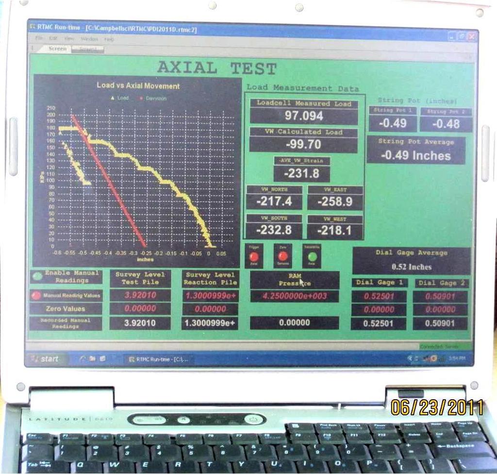
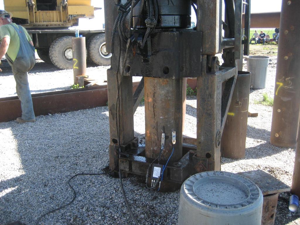
13 Reaction Beam Static Load Test Load Application and Monitoring Components Spherical Bearing Plates Load Cell Hydraulic Jack Reference Beam Vishay Box Jack Pressure Gage Jack Pump

14 Load Test Movement Monitoring Components Reference Beam Dial Gage LVDT Smooth Surface Magnetic Base

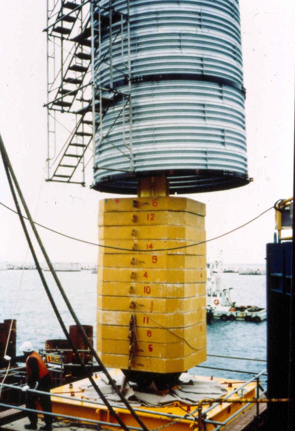
15 Jack Against Weighted Platform
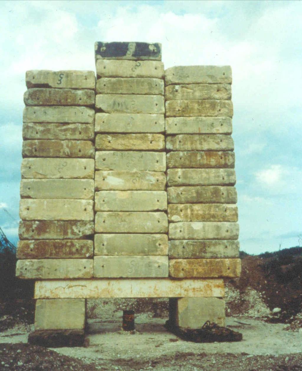
16

17 Direct Load Application

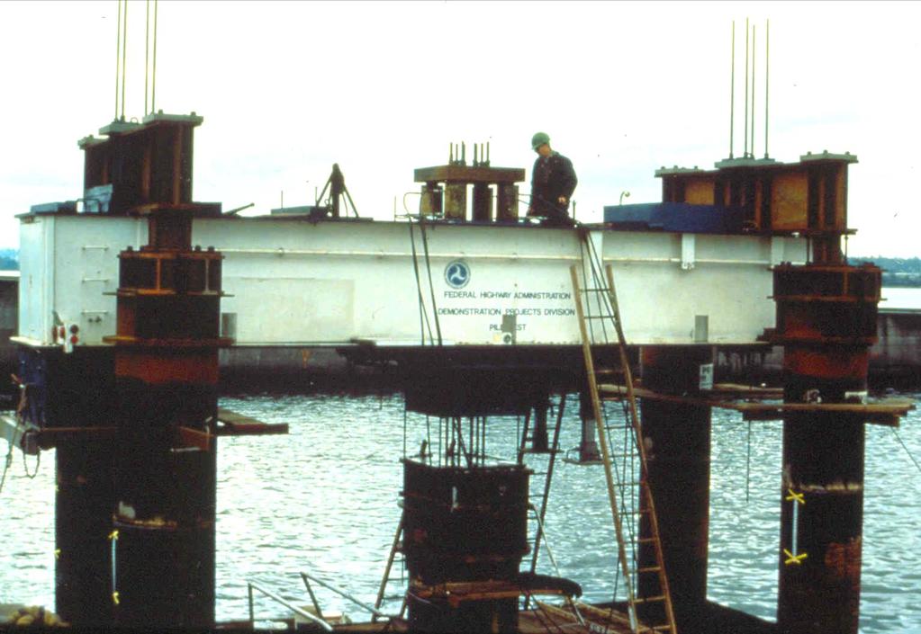
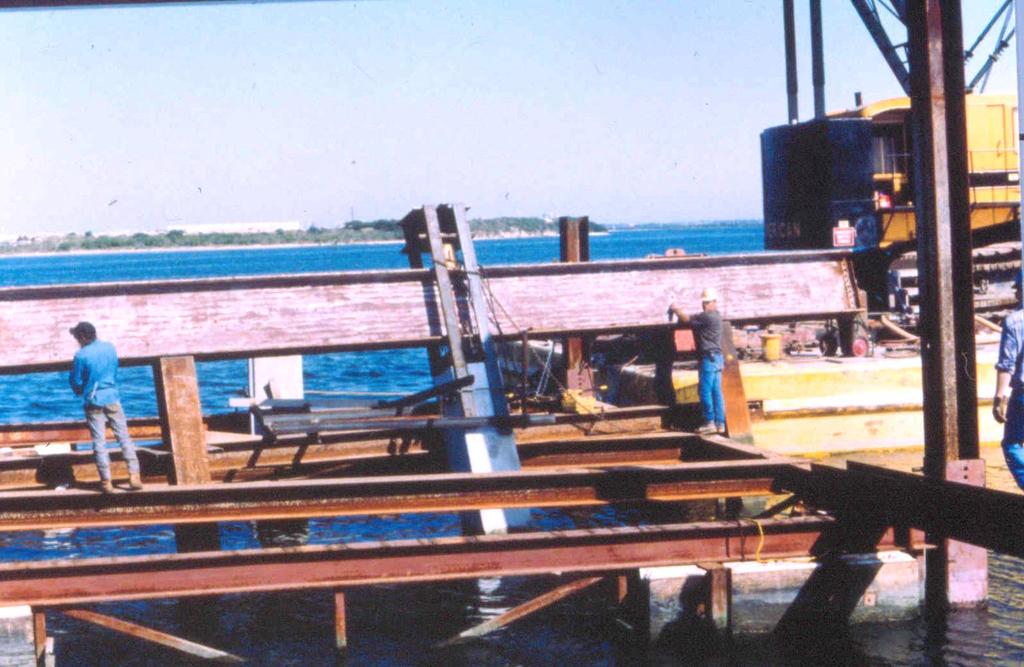
18 Jack Against Reaction Beam and Piles
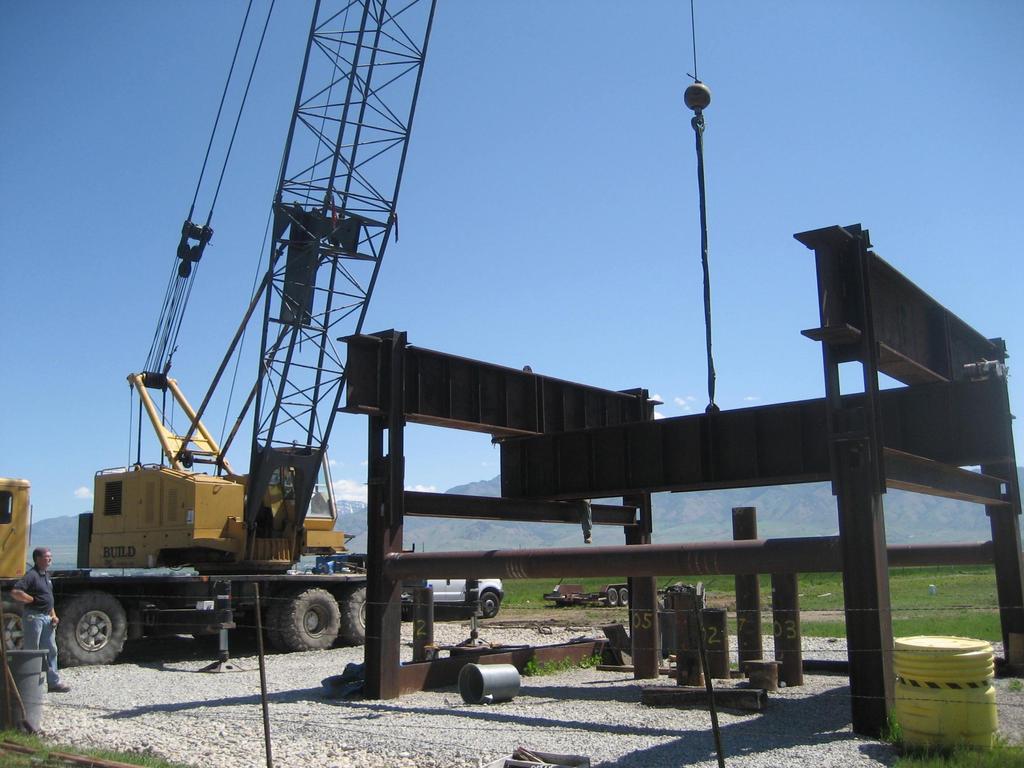
19
20
21

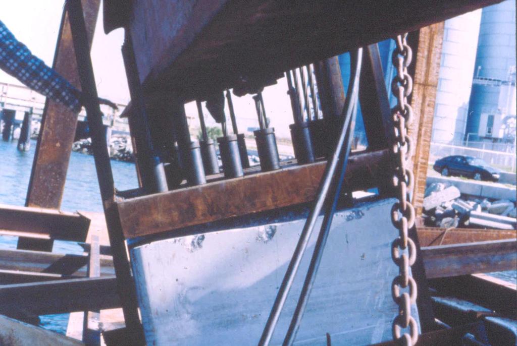
22 Load Test Hardware Reaction Beam Spacers Spherical Bearing Plate Ram Hydraulic Jack Test Pile Load Cell
23
24
25 FAILURE CRITERIA The commonly used failure criteria are based on the elastic pile compression plus an offset. Davisson Method The elastic compression, Δ, is calculated as follows: Δ = PL / AE Where: P = axial load in kn (kips) L = pile length in mm (in) A = pile cross sectional area in m 2 (in 2 ) E = elastic modulus of the pile material in kpa (ksi)
26 FAILURE CRITERIA (b < 24 in) The recommended offset is based on the pile diameter. In US Units s f = + (0.15 +b/120) In SI Units s f = + ( b) Where: s f = Settlement at failure load in inches (mm) b = Pile diameter or width in inches (mm) = Elastic deformation of total pile length in inches (mm)
27 FAILURE CRITERIA (b > 24 in) The recommended offset is based on the pile diameter. s f = + (b / 30) Where: s f = Settlement at failure load in inches (mm) b = Pile diameter or width in inches (mm) = Elastic deformation of total pile length in inches (mm)
28

29 CalTRANS Pile Load Testing 4000-Ton Mobile Compression or Tension Test Frame
30
 Failure in compression as a production pile? Why?")
31 QUESTION Would you feel comfortable using a pile that has been tested to geotechnical (plunging) Failure in compression as a production pile? Why? / Why not?
32 LOAD TRANSFER EVALUATIONS Determine relative resistance contributions from shaft and toe. Determine load transfer behavior along shaft (shaft resistance distribution). Confirm, correlate, and calibrate static analyses, WEAP input, CAPWAP soil resistance distributions. Refine dragload magnitudes.


33 VWSG with welded anchor blocks and protective channel VWSG sister bars for concrete embedment
34 Elevation (ft) Elevation, feet (USGS Datum) 605 Calculated Calculated Axial Axial Compression Load Load in Pile, in tons Pile (tons) , , tons / [ 12.3 ft (3.67 ft) ] = 0.36 tsf
 Unit Load Transfer, t t = (Q 2 - Q 3 ) / (π DL) Displacement, z z = (Displ.")
35 T-Z CURVES 101 Based on the previous data/graph, we have an idea of load versus depth T-Z Curves show load transfer from one point to another (i.e., pt. 2 to pt. 3) Unit Load Transfer, t t = (Q 2 - Q 3 ) / (π DL) Displacement, z z = (Displ. at top) Σ(ε*ΔL)
36 T-Z CURVES 101 We can now relate the unit skin friction/load transfer to the displacement This allows us to determine loadsettlement relationships

 / (π r 2 ) Toe Displacement, z z = (Displ.")
37 Q-Z (or Q-W) CURVES 101 Based on the previous data/graph, we can also address end bearing Q-Z Curves show load transfer at the pile toe End Bearing Pressure, q q = (Q 4 ) / (π r 2 ) Toe Displacement, z z = (Displ. at top) Σ(ε*ΔL)

38 T-Z CURVES 101 Residual Stresses

39 TENSION TESTING (UPLIFT CAPACITY) SHIP IMPACT SEISMIC EVENT LATERAL LOADING
40
41
42
43 19-22
44 STUDENT EXERCISE #9 (FYI ) An axial compression static load test has been performed and the results must be interpreted to determine if the pile has an ultimate capacity in excess of the required ultimate capacity. The load - movement curve from the static load on a 16 inch square prestressed concrete pile is presented on the following page. The pile has a cross sectional area, A, of 256 in 2 and a length, L, of 100 ft. The concrete compression strength, f'c is 6.0 ksi. The pile has a required ultimate pile capacity of 800 kips.
45 Osterberg Cell Method O-Cell Reference Manual Chapter 19
46 Comparison Between Standard Load Test and Osterberg Cell Test
47 Osterberg Cell PORTABLE COMPUTER BOTTOM PLATE TELLTALE INDICATOR TOP OF PILE INDICATOR REFERENCE BEAM Cast in Pile DATA LOGGER PILE COMPRESSION INDICATOR PRESSURE TRANSDUCER HYDRAULIC PUMP WITH PRESSURE GAUGE PILE SHAFT RESISTANCE TELLTALE CASINGS HYDRAULIC RETURN LINE HYDRAULIC SUPPLY LINE OSTERBERG CELL CAST INTO PILE PILE TOE RESISTANCE
48

49 Osterberg Load Cell Test Socket Load Cell Reaction Socket 14-17
50
51 Aucilla River Subsurface Profile 2.1m 3.2m Dense Silty Sand Silty Clay with Sand Lenses 21.3m 15.3m 0.7m Limerock
52 Aucilla River Test Results
53 O-CELL ADVANTAGES Reduced Cost & Improved Safety No External Reaction System is Required End Bearing & Shaft Friction Measured Test Over Water High Capacity
54 O-CELL DISADVANTAGES Limited to displacement piles Pile selection in advance O-Cell is expendable Specialists are required Patented Ultimate capacity is NOT determined Void is created after unloading
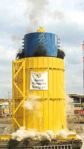
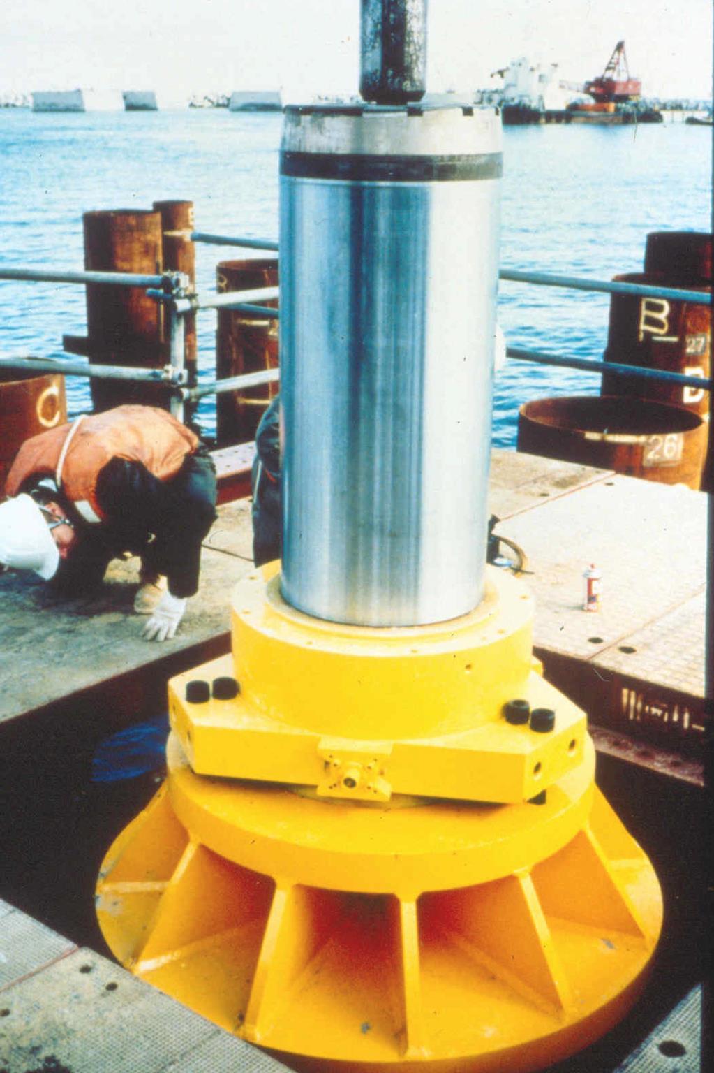
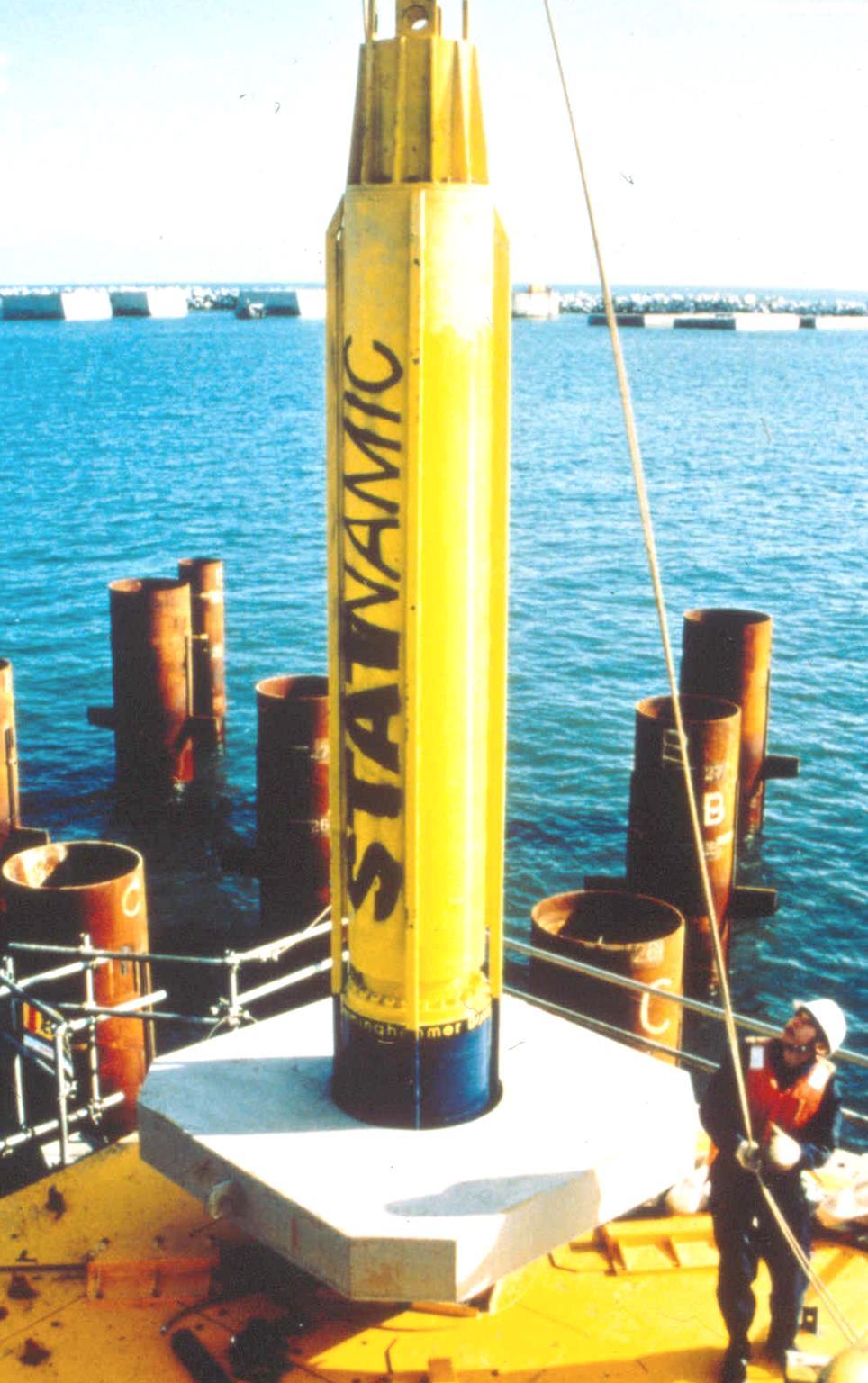
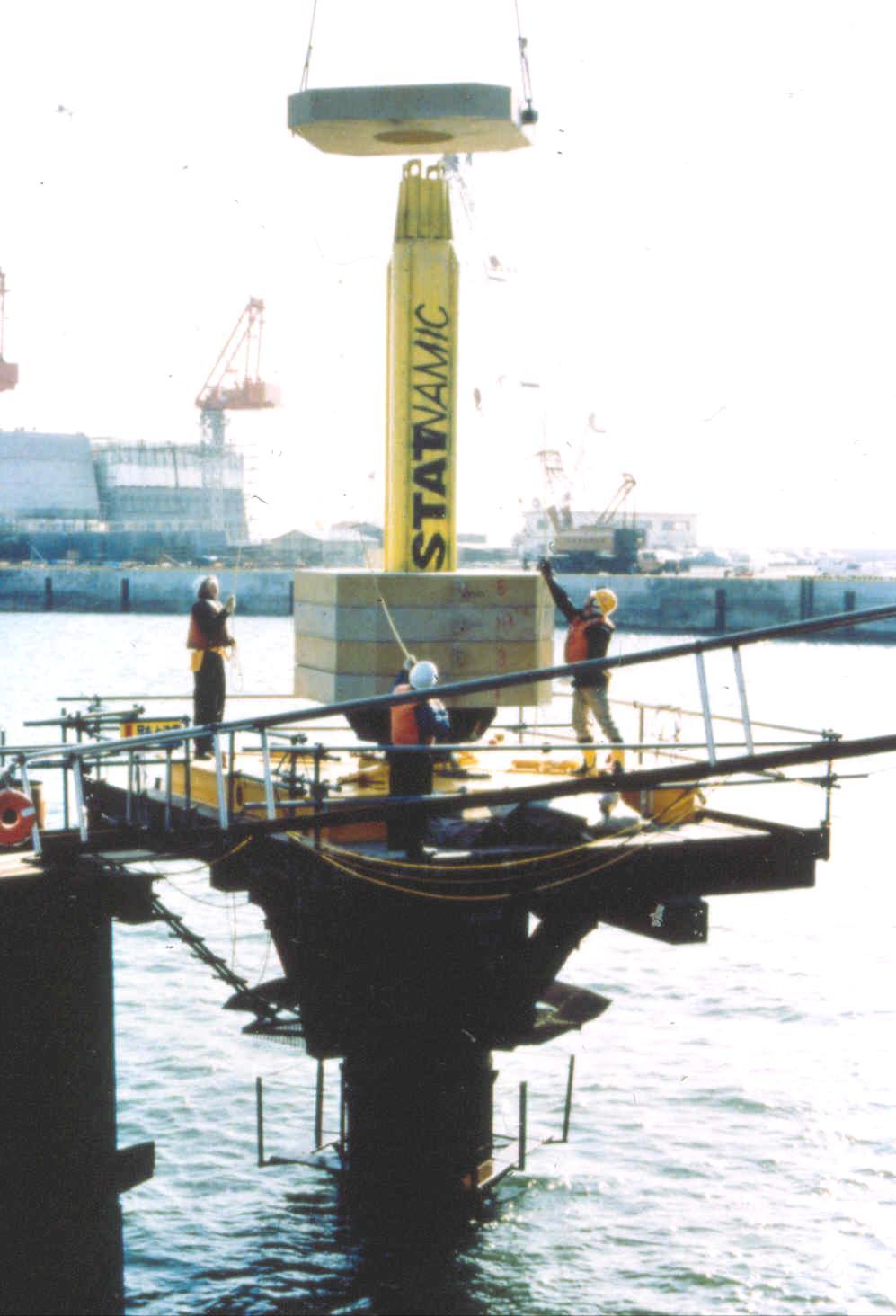
55 Statnamic Method Reference Manual Chapter 20


56 Statnamic Concept

57 1000 Kip Device 9000 Kip Device

58 Retention Structure Schematic
59
60
61
62

63 Accelerometers attached to the pile top surface are now more commonly used to obtain displacement instead of laser.
64

65
66
67
68 Load Movement Plot From Load Cell & Laser Data
69 Displacement (mm) Derived Statnamic Load Displacement Curve (UPM) Load (MN)
70 Loading Rate Reduction Factors NCHRP (2002) recommended a loading rate reduction factor also be applied to account for over-predictions associated with loading rate. Recommended reduction factors are: Rock = 0.96 Sand = 0.91 Silt = 0.69 Clay = 0.65
71 STATNAMIC TEST RESULT 1067 mm O.D. Open End Pipe Pile Derived Static with Rate Factor FHWA Failure Line
72 STATNAMIC ADVANTAGES Cost & Speed External Reaction System Not Required Works on Battered Piles
73 STATNAMIC DISADVANTAGES Dynamic Test Proprietary Specially Trained Personnel
74 Any Questions?
INCREASE IN PILE CAPACITY WITH TIME IN MISSOURI RIVER ALLUVIUM
 INCREASE IN PILE CAPACITY WITH TIME IN MISSOURI RIVER ALLUVIUM Paul J. Axtell Jacob W. Owen Scott D. Vollink U.S. Army Corps of Engineers U.S. Army Corps of Engineers U.S. Army Corps of Engineers Kansas
This document downloaded from vulcanhammer.net vulcanhammer.info Chet Aero Marine
 This document downloaded from vulcanhammer.net vulcanhammer.info Chet Aero Marine Don t forget to visit our companion site http://www.vulcanhammer.org Use subject to the terms and conditions of the respective
S E C T I O N 1 2 P R O D U C T S E L E C T I O N G U I D E - H E L I C A L S C R E W P I L E F O U N D A T I O N S
 1. P R O D U C T S E L E C T I O N G U I D E - H E L I C A L S C R E W P I L E F O U N D A T I O N S Helical foundation pile includes a lead and extension(s). The lead section is made of a central steel
INTRODUCTION TO STATIC ANALYSIS PDPI 2013
 INTRODUCTION TO STATIC ANALYSIS PDPI 2013 What is Pile Capacity? When we load a pile until IT Fails what is IT Strength Considerations Two Failure Modes 1. Pile structural failure controlled by allowable
OP-023. INTERPRETATION OF INSTRUMENTED TEST PILE RESULT
 INTERPRETATION OF INSTRUMENTED TEST PILE RESULT Page 1 of 9 WORK INSTRUCTIONS FOR ENGINEERS GSJ Compiled by : Checked by KYW : LSS Approved by : OP-23. INTERPRETATION OF INSTRUMENTED TEST PILE RESULT INTERPRETATION
Drilled Shaft Foundations in Limestone. Dan Brown, P.E., Ph.D. Dan Brown and Associates
 Drilled Shaft Foundations in Limestone Dan Brown, P.E., Ph.D. Dan Brown and Associates Foundation Engineering How we teach our students Fundamental understanding of soil and rock behavior (good!) Focus
Deep Foundations 2. Load Capacity of a Single Pile
 Deep Foundations 2 Load Capacity of a Single Pile All calculations of pile capacity are approximate because it is almost impossible to account for the variability of soil types and the differences in the
APPLICATION OF GLOBAL STRAIN EXTENSOMETER (GLOSTREXT) METHOD FOR INSTRUMENTED BORED PILES IN MALAYSIA
 METHOD FOR INSTRUMENTED BORED PILES IN MALAYSIA") Paper published in 1 th International Conference on Piling and Deep Foundations, 31 st May 2 nd June, Amsterdam. APPLICATION OF GLOBAL STRAIN EXTENSOMETER (GLOSTREXT) METHOD FOR INSTRUMENTED BORED PILES
Paper published in 1 th International Conference on Piling and Deep Foundations, 31 st May 2 nd June, Amsterdam. APPLICATION OF GLOBAL STRAIN EXTENSOMETER (GLOSTREXT) METHOD FOR INSTRUMENTED BORED PILES
Calibration of Resistance Factors for Drilled Shafts for the 2010 FHWA Design Method
 Calibration of Resistance Factors for Drilled Shafts for the 21 FHWA Design Method Murad Y. Abu-Farsakh, Ph.D., P.E. Qiming Chen, Ph.D., P.E. Md Nafiul Haque, MS Feb 2, 213 213 Louisiana Transportation
Lateral Resistance of Short Rock Sockets in Weak Rock: a Case History. Text word count: 4140 Number of figures and tables: 13
 Lateral Resistance of Short Rock Sockets in Weak Rock: a Case History Text word count: Number of figures and tables: 1 Robert L. Parsons PhD, P.E (Corresponding Author) Associate Professor Department of
Implementation of Pile Setup in the LRFD Design of Driven Piles in Louisiana
 Implementation of Pile Setup in the LRFD Design of Driven Piles in Louisiana Md. Nafiul Haque (Ph.D. Candidate) Murad Y. Abu-Farsakh, Ph.D., P.E. March 1, 2016 Louisiana Transportation Conference OUTLINE
BACKGROUND AND INTRODUCTION
 WAVE MECHANICS As applied to pile testing 1 BACKGROUND AND INTRODUCTION Wave Mechanics 2 1 HISTORIC TOOLS AND MATERIALS Timber piles Drop Hammers 10 Days for the Romans to build the bridge over the Rhine
In-class Exercise. Problem: Select load factors for the Strength I and Service I Limit States for the. Loading Diagram for Student Exercise
 In-class Exercise Problem: Select load factors for the Strength I and Service I Limit States for the problem illustrated below. Loading Diagram for Student Exercise For this exercise, complete the following
Additional Pile Design Considerations
 Additional Pile Design Considerations PDCA 2015 Professor Driven Pile Institute Patrick Hannigan GRL Engineers, Inc. What Are Additional Pile Design Considerations? Time Dependent Soil Strength Changes
PERFORMANCE OF BITUMINOUS COATS IN REDUCING NEGATIVE SKIN
 PERFORMANCE OF BITUMINOUS COATS IN REDUCING NEGATIVE SKIN FRICTION Makarand G. Khare, PhD Research Scholar, Indian Institute of Technology Madras, Chennai, India Shailesh R. Gandhi, Professor, Indian Institute
Analysis of a single pile settlement
 Engineering manual No. 14 Updated: 06/2018 Analysis of a single pile settlement Program: Pile File: Demo_manual_14.gpi The objective of this engineering manual is to explain the application of the GEO
vulcanhammer.info the website about Vulcan Iron Works Inc. and the pile driving equipment it manufactured Terms and Conditions of Use:
 this document downloaded from vulcanhammer.info the website about Vulcan Iron Works Inc. and the pile driving equipment it manufactured Terms and Conditions of Use: All of the information, data and computer
CPT Guide 5 th Edition. CPT Applications - Deep Foundations. Gregg Drilling & Testing, Inc. Dr. Peter K. Robertson Webinar # /2/2013
 Gregg Drilling & Testing, Inc. Site Investigation Experts CPT Applications - Deep Foundations Dr. Peter K. Robertson Webinar #6 2013 CPT Guide 5 th Edition Robertson & Cabal (Robertson) 5 th Edition 2012
Rapid Load Test from Theory to Practice in Singapore. 1. Introduction
 GEOSS SEMINAR 2014 on PILE LOAD TESTS IN SINGAPORE Presentation on Rapid Load Test from Theory to Practice in Singapore By Dr. Chew Soon Hoe Assistant Professor National University of Singapore ceecsh@nus.edu.sg
LRFD Application in Driven Piles (Recent Development in Pavement & Geotech at LTRC)
") LRFD Application in Driven Piles (Recent Development in Pavement & Geotech at LTRC) 2007 Louisiana Transportation Engineering Conference February 12, 2007 Sungmin Sean Yoon, Ph. D., P.E. and Murad Abu-Farsakh,
LRFD Application in Driven Piles (Recent Development in Pavement & Geotech at LTRC) 2007 Louisiana Transportation Engineering Conference February 12, 2007 Sungmin Sean Yoon, Ph. D., P.E. and Murad Abu-Farsakh,
Understanding Dynamic Pile Testing and Driveability
 008-015 understand dynamic 5/30/06 5:10 PM Page 8 Understanding Dynamic Pile Testing and Driveability... By: Engr. Dr Sam Ming Tuck MIEM, P.Eng INTRODUCTION Traditionally, piles are static load tested
Comparison of Static and Dynamic Pile Load Tests at Thi Vai International Port in Viet Nam
 Comparison of Static and Dynamic Pile Load Tests at Thi Vai International Port in Viet Nam Le Phan Ta, Ph.D student, Graduate School of Kanazawa University, Japan (HCMC University of Architecture, Viet
DRILLED DISPLACMENT PILE PERFORMANCE IN COASTAL PLAIN AND RESIDUAL SOILS
 DRILLED DISPLACMENT PILE PERFORMANCE IN COASTAL PLAIN AND RESIDUAL SOILS Presented by: W. Morgan NeSmith, P.E. Berkel & Company Contractors Inc. 770.941.5100 mnesmith@berkelapg.com SC Engineering Conference
Axially Loaded Piles
 Axially Loaded Piles 1 t- Curve Method using Finite Element Analysis The stress-strain relationship for an axially loaded pile can be described through three loading mechanisms: axial deformation in the
PILE SETUP LA-1 EXPERIENCE. Ching-Nien Tsai, P.E.
 PILE SETUP LA-1 EXPERIENCE Ching-Nien Tsai, P.E. Bayou Lafourche Mississippi River GEOTECHNICAL INVESTIGATION PROGRAM 102 CPT soundings Depths from 100 feet to 200 feet 118 borings Depths from
SHEET PILE WALLS. Mehdi Mokhberi Islamic Azad University
 SHEET PILE WALLS Mehdi Mokhberi Islamic Azad University Lateral Support In geotechnical engineering, it is often necessary to prevent lateral soil movements. Tie rod Anchor Sheet pile Cantilever retaining
Use of Ultra-High Performance Concrete in Geotechnical and Substructure Applications
 Use of Ultra-High Performance Concrete in Geotechnical and Substructure Applications i PI: Muhannad Suleiman Co-PI: Sri Sritharan Graduate Research Assistant: Thomas L. Vande Voort January 13, 29 IOWA
CHAPTER II EXPERIMENTAL INVESTIGATION
 CHAPTER II EXPERIMENTAL INVESTIGATION 2.1 SCOPE OF TESTING The objective of this research is to determine the force distribution between the column web and stiffener when the column flanges are subjected
WIND TUNNEL TESTING GEOTECHNICAL STUDY
 WIND TUNNEL TESTING Wind tunnel testing was conducted by the Boundary Layer Wind Tunnel Laboratory (BLWTL) at the University of Western Ontario (UWO) to develop wind load time histories for the chimney.
CAPWAP Introduction. 2016, Pile Dynamics, Inc. CAPWAP is a registered trademark of Pile Dynamics, Inc. Load (kn) Displacement (mm) Pile Top Bottom
 Displacement (mm) Pile Top Bottom") CAPWAP Introduction Load (kn) 0.0 1000.0 2000.0 3000.0 4000.0 0.00 Pile Top Bottom Displacement (mm) 5.00 10.00 Ru = Rs = Rb = Dy = Dx = 3425.2 kn 1458.6 kn 1966.6 kn 18.8 mm 18.8 mm 15.00 20.00 2016,
CAPWAP Introduction Load (kn) 0.0 1000.0 2000.0 3000.0 4000.0 0.00 Pile Top Bottom Displacement (mm) 5.00 10.00 Ru = Rs = Rb = Dy = Dx = 3425.2 kn 1458.6 kn 1966.6 kn 18.8 mm 18.8 mm 15.00 20.00 2016,
Liquefaction Induced Negative Skin Friction from Blast-induced Liquefaction Tests with Auger-cast Piles
 6 th International Conference on Earthquake Geotechnical Engineering 1-4 November 2015 Christchurch, New Zealand Liquefaction Induced Negative Skin Friction from Blast-induced Liquefaction Tests with Auger-cast
Neutral Plane Method for Drag Force of Deep Foundations and the AASHTO LRFD Bridge Design Specifications
 Neutral Plane Method for Drag Force of Deep Foundations and the AASHTO LRFD Bridge Design Specifications Timothy C. Siegel, P.E., G.E., D.GE Dan Brown and Associates, PC, Knoxville, Tennessee USA Rich
CAPWAP rules Important!
 CAPWAP rules Important! Unit friction < 4 ksf (200 kpa ) for most soils QT (+TG) < Dmax, toe to assure activation QS < 0.2 inch (5 mm ) usually 0.1 inch; 2.5 mm SS, ST < 0.4 s/ft (1.3 s/m ) if higher,
CHAPTER 8 CALCULATION THEORY
 CHAPTER 8 CALCULATION THEORY. Volume 2 CHAPTER 8 CALCULATION THEORY Detailed in this chapter: the theories behind the program the equations and methods that are use to perform the analyses. CONTENTS CHAPTER
Foundation Engineering Prof. Mahendra Singh Department of Civil Engineering Indian Institute of Technology, Roorkee
 Foundation Engineering Prof. Mahendra Singh Department of Civil Engineering Indian Institute of Technology, Roorkee Module - 03 Lecture - 05 Field Tests Hello viewers, welcome back to the course on Foundation
Interpretation of Pile Integrity Test (PIT) Results
 Results") Annual Transactions of IESL, pp. 78-84, 26 The Institution of Engineers, Sri Lanka Interpretation of Pile Integrity Test (PIT) Results H. S. Thilakasiri Abstract: A defect present in a pile will severely
Annual Transactions of IESL, pp. 78-84, 26 The Institution of Engineers, Sri Lanka Interpretation of Pile Integrity Test (PIT) Results H. S. Thilakasiri Abstract: A defect present in a pile will severely
LRFD GEOTECHNICAL IMPLEMENTATION
 LRFD GEOTECHNICAL IMPLEMENTATION Ching-Nien Tsai, P.E. LADOTD Pavement and Geotechnical Services In Conjunction with LTRC WHY LRFD FHWA deadline - October 2007 LRFD is a better method Risk is quantified
Experimental Investigation of Steel Pipe Pile to Concrete Cap Connections
 Brigham Young University BYU ScholarsArchive All Theses and Dissertations 211-4-19 Experimental Investigation of Steel Pipe Pile to Concrete Cap Connections Ryan S. Eastman Brigham Young University - Provo
LOAD RESISTANCE FACTOR DESIGN (LRFD) FOR DRIVEN PILES BASED ON DYNAMIC METHODS WITH ASSESSMENT OF SKIN AND TIP RESISTANCE FROM PDA SIGNALS
 FOR DRIVEN PILES BASED ON DYNAMIC METHODS WITH ASSESSMENT OF SKIN AND TIP RESISTANCE FROM PDA SIGNALS") LOAD RESISTANCE FACTOR DESIGN (LRFD) FOR DRIVEN PILES BASED ON DYNAMIC METHODS WITH ASSESSMENT OF SKIN AND TIP RESISTANCE FROM PDA SIGNALS By ARIEL PEREZ PEREZ A THESIS PRESENTED TO THE GRADUATE SCHOOL
LOAD RESISTANCE FACTOR DESIGN (LRFD) FOR DRIVEN PILES BASED ON DYNAMIC METHODS WITH ASSESSMENT OF SKIN AND TIP RESISTANCE FROM PDA SIGNALS By ARIEL PEREZ PEREZ A THESIS PRESENTED TO THE GRADUATE SCHOOL
DEEP FOUNDATIONS. Lesson 09 - Topic 4 Drilled Shafts
 DEEP FOUNDATIONS Lesson 09 - Topic 4 Drilled Shafts Learning Outcomes gat the end of this session, the participant will be able to: - Contrast driven piles and drilled shafts - Compare mobilization of
Improving site specific modified driving formulae using high frequency displacement monitoring
 Proc. 20 th NZGS Geotechnical Symposium. Eds. GJ Alexander & CY Chin, Napier Improving site specific modified driving formulae using high frequency displacement monitoring R Damen Brian Perry Civil, Auckland,
Chapter 7: Settlement of Shallow Foundations
 Chapter 7: Settlement of Shallow Foundations Introduction The settlement of a shallow foundation can be divided into two major categories: (a) elastic, or immediate settlement and (b) consolidation settlement.
Analysis of the horizontal bearing capacity of a single pile
 Engineering manual No. 16 Updated: 07/2018 Analysis of the horizontal bearing capacity of a single pile Program: Soubor: Pile Demo_manual_16.gpi The objective of this engineering manual is to explain how
LRFD Calibration of Axially-Loaded Concrete Piles Driven into Louisiana Soils
 LRFD Calibration of Axially-Loaded Concrete Piles Driven into Louisiana Soils Louisiana Transportation Conference February 10, 2009 Sungmin Sean Yoon, Ph. D., P.E. (Presenter) Murad Abu-Farsakh, Ph. D.,
PILE LOAD TEST IN OLD ALLUVIUM
 An evening talk organized by GeoSS PILE LOAD TEST IN OLD ALLUVIUM Wong Kai Sin 25 August 2016 1 PILE LOAD TEST IN OLD ALLUVIUM 1.Should we accept or reject the test results? 2.What are the expected unit
FLAC3D analysis on soil moving through piles
 University of Wollongong Research Online Faculty of Engineering - Papers (Archive) Faculty of Engineering and Information Sciences 211 FLAC3D analysis on soil moving through piles E H. Ghee Griffith University
Seismic Pushover Analysis Using AASHTO Guide Specifications for LRFD Seismic Bridge Design
 Seismic Pushover Analysis Using AASHTO Guide Specifications for LRFD Seismic Bridge Design Elmer E. Marx, Alaska Department of Transportation and Public Facilities Michael Keever, California Department
Bored Sockets in weathered Basalt
 Bored Sockets in weathered Basalt L. Maertens Manager Engineering Department Besix, Belgium Associate Professor Catholic University Leuven Keywords: sockets, open-end piles, tensile piles, basalt ABSTRACT:
Maximum Envelope of Lateral Resistance through Dynamic Increasing Energy Test in Piles
 Maximum Envelope of Lateral Resistance through Dynamic Increasing Energy Test in Piles R.M. Valverde, F. Massad Abstract. The traditional dynamic load test, based on the one-dimensional wave propagation
Engineeringmanuals. Part2
 Engineeringmanuals Part2 Engineering manuals for GEO5 programs Part 2 Chapter 1-12, refer to Engineering Manual Part 1 Chapter 13. Pile Foundations Introduction... 2 Chapter 14. Analysis of vertical load-bearing
TC211 Workshop CALIBRATION OF RIGID INCLUSION PARAMETERS BASED ON. Jérôme Racinais. September 15, 2015 PRESSUMETER TEST RESULTS
 Jérôme Racinais September 15, 215 TC211 Workshop CALIBRATION OF RIGID INCLUSION PARAMETERS BASED ON PRESSUMETER TEST RESULTS Table of contents 1. Reminder about pressuremeter tests 2. General behaviour
Views on Accuracy of Tests and Analyses
 Piling & Deep Foundations Asia 29 Workshop A, July 13, 29 Views on Accuracy of Tests and Analyses Bengt H. Fellenius ======================================================================================================================
Discussion: behaviour of jacked and driven piles in sandy soil
 Title Discussion: behaviour of jacked and driven piles in sandy soil Author(s) Yang, J; Tham, LG; Lee, PKK; Chan, ST; Yu, F Citation Géotechnique, 27, v. 7 n., p. 47-478 Issued Date 27 URL http://hdl.handle.net/1722/7161
SIDE FRICTION OF DRILLED PILES IN COBBLE LAYERS
 This article has been peer reviewed and accepted for publication in JMST but has not yet been copyediting, typesetting, pagination and proofreading process. Please note that the publication version of
Prof. B V S Viswanadham, Department of Civil Engineering, IIT Bombay
 56 Module 4: Lecture 7 on Stress-strain relationship and Shear strength of soils Contents Stress state, Mohr s circle analysis and Pole, Principal stressspace, Stress pathsin p-q space; Mohr-Coulomb failure
AN ABSTRACT OF THE THESIS OF
 AN ABSTRACT OF THE THESIS OF Nasim Adami for the degree of Master of Science in Civil Engineering presented on October 28, 213. Title: Development of an ACIP Pile-Specific Load-Displacement Model. Abstract
STUDY OF THE BEHAVIOR OF PILE GROUPS IN LIQUEFIED SOILS
 STUDY OF THE BEHAVIOR OF PILE GROUPS IN LIQUEFIED SOILS Shin-Tower Wang 1, Luis Vasquez 2, and Lymon C. Reese 3, Honorary Member,, ASCE ABSTRACT : 1&2 President & Project Manager, Ensoft, Inc. Email: ensoft@ensoftinc.com
CHAPTER 7 ANALYSES OF THE AXIAL LOAD TESTS AT THE ROUTE 351 BRIDGE
 CHAPTER 7 ANALYSES OF THE AXIAL LOAD TESTS AT THE ROUTE 351 BRIDGE 7.1 INTRODUCTION In this chapter, calculations using methods commonly employed in practice are presented for the pile axial load capacity,
User Guide for FB-Deep F.C. Townsend
 User Guide or FB-Deep F.C. Townsend Intro: FB-Deep (ormerly SHAFT-SPT) is a combination o SHAFT 98, which uses the FHWA O Neill & Reese method or drilled shats and intermediate geomaterials, and SPT97,
Landslide FE Stability Analysis
 Landslide FE Stability Analysis L. Kellezi Dept. of Geotechnical Engineering, GEO-Danish Geotechnical Institute, Denmark S. Allkja Altea & Geostudio 2000, Albania P. B. Hansen Dept. of Geotechnical Engineering,
Evaluation of Geotechnical Hazards
 Evaluation of Geotechnical Hazards by Geoffrey R. Martin Appendix B: Evaluation of Geotechnical Hazards Describes Evaluation Procedures Soil Liquefaction Soil Settlement Surface Fault Rupture Flooding
PDA Workshop: Stresses, Integrity, Energy and Capacity
 PDA Workshop: Stresses, Integrity, Energy and Capacity Ir Richard C L Yu IEM 2 Sep 2013 Dynamic Pile Monitoring For each blow determine Pile driving stresses Pile integrity Hammer performance Capacity
Christian Linde Olsen Griffith University, Faculty of Engineering and Information Technology, Gold Coast Campus.
 1 Introduction Test on Cyclic Lateral Loaded Piles in Sand Christian Linde Olsen Griffith University, Faculty of Engineering and Information Technology, Gold Coast Campus. Abstract The following paper
SCHOOL OF CIVIL ENGINEERING
 SCHOOL OF CIVIL ENGINEERING JOINT HIGHWAY RESEARCH PROJECT FHWA/IN/JHRP-87/l - ( Final Report PILE CAPACITY PREDICTIONS USINC STATIC AND DYNAMIC LOAD TESTIN( Ahmad Amr Darrag $ UNIVERSITY JOINT HIGHWAY
Bearing Capacity of Soils in Deep Foundations Course No. CE0148 PDH: 5
 Bearing Capacity of Soils in Deep Foundations Course No. CE0148 PDH: 5 ** PLEASE NOTE: THIS COURSE IS A SUBSECTION OF COURSE # CE0009 ** In order to obtain credit for this course, the following steps listed
Solid Mechanics Homework Answers
 Name: Date: Solid Mechanics Homework nswers Please show all of your work, including which equations you are using, and circle your final answer. Be sure to include the units in your answers. 1. The yield
INTI COLLEGE MALAYSIA
 EGC373 (F) / Page 1 of 5 INTI COLLEGE MALAYSIA UK DEGREE TRANSFER PROGRAMME INTI ADELAIDE TRANSFER PROGRAMME EGC 373: FOUNDATION ENGINEERING FINAL EXAMINATION : AUGUST 00 SESSION This paper consists of
CHAPTER 8 ANALYSES OF THE LATERAL LOAD TESTS AT THE ROUTE 351 BRIDGE
 CHAPTER ANALYSES OF THE LATERAL LOAD TESTS AT THE ROUTE 351 BRIDGE.1 INTRODUCTION An important objective of this research is to determine whether accurate analyses of the lateral load-deflection behavior
Full-Scale Testing of Blast-Induced Liquefaction Downdrag on Driven Piles in Sand
 Brigham Young University BYU ScholarsArchive All Theses and Dissertations 2017-07-01 Full-Scale Testing of Blast-Induced Liquefaction Downdrag on Driven Piles in Sand Luke Ian Kevan Brigham Young University
UNIVERSITY OF AKRON Department of Civil Engineering
 UNIVERSITY OF AKRON Department of Civil Engineering 4300:401-301 July 9, 2013 Steel Design Sample Quiz 2 1. The W10 x 54 column shown has both ends pinned and consists of A992 steel (F y = 50 ksi, F u
1.105 Solid Mechanics Laboratory Fall 2003 Experiment 3 The Tension Test
 1.105 Solid Mechanics Laboratory Fall 2003 Experiment 3 The Tension Test Our objective is to measure the Elastic Modulus of steel. The experiment comes in two parts. In the first, you will subject a steel
vulcanhammer.info the website about Vulcan Iron Works Inc. and the pile driving equipment it manufactured Terms and Conditions of Use:
 this document downloaded from vulcanhammer.info the website about Vulcan Iron Works Inc. and the pile driving equipment it manufactured Terms and Conditions of Use: All of the information, data and computer
Influence of Relative Compaction on Passive Resistance of Abutments with Mechanically Stabilized Earth (MSE) Wingwalls
 Wingwalls") Brigham Young University BYU ScholarsArchive All Theses and Dissertations 2010-08-11 Influence of Relative Compaction on Passive Resistance of Abutments with Mechanically Stabilized Earth (MSE) Wingwalls
Brigham Young University BYU ScholarsArchive All Theses and Dissertations 2010-08-11 Influence of Relative Compaction on Passive Resistance of Abutments with Mechanically Stabilized Earth (MSE) Wingwalls
Calibration of Resistance Factors for Driven Piles using Static and Dynamic Tests
 University of Arkansas, Fayetteville ScholarWorks@UARK Theses and Dissertations 12-2014 Calibration of Resistance Factors for Driven Piles using Static and Dynamic Tests Deshinka A. Bostwick University
EFFECT OF SOIL TYPE LOCATION ON THE LATERALLY LOADED SINGLE PILE
 International Journal of Civil Engineering and Technology (IJCIET) Volume 9, Issue 12, December 2018, pp. 1196 1205, Article ID: IJCIET_09_12 122 Available online at http://www.ia aeme.com/ijciet/issues.asp?jtype=ijciet&vtype=
Standard Test Method for High-Strain Dynamic Testing of Deep Foundations 1
 Designation: D4945 12 Standard Test Method for High-Strain Dynamic Testing of Deep Foundations 1 This standard is issued under the fixed designation D4945; the number immediately following the designation
TRANSPORTATION RESEARCH BOARD. Static and Seismic Design of Piles for Downdrag. Thursday, October 4, :00-3:30 PM ET
 TRANSPORTATION RESEARCH BOARD Static and Seismic Design of Piles for Downdrag Thursday, October 4, 2018 2:00-3:30 PM ET The Transportation Research Board has met the standards and requirements of the Registered
Comparisons of rapid load test, dynamic load test and static load test on driven piles
 Comparisons of rapid load test, dynamic load test and static load test on driven piles Bamrungwong, C., Chaisukhang, J. & Janmonta, K. Department of Rural Roads, Thailand Kitiyodom, P. Geotechnical & Foundation
Implementation of Laterally Loaded Piles in Multi-Layer Soils
 Implementation of Laterally Loaded Piles in Multi-Layer Soils JTRP SPR- 3261 Final SAC meeting SAC members Mir Zaheer and Keith Hoernschemeyer Purdue University Introduction Analysis developed for the
PECivilExam.com. Copyright 2015 Pecivilexam.com all rights reserved- E-Book Geotechnical Depth Exam: 80 problems
 PECivilExam.com PE Civil Exam 80- Geotechnical Questions & Answers (pdf Format) For Depth Exam (Evening Session) PE Civil Depth Exam (Evening Session): This practice exam contains 80- Geotechnical questions,
[5] Stress and Strain
![[5] Stress and Strain](/thumbs/95/123344550.jpg "[5] Stress and Strain") [5] Stress and Strain Page 1 of 34 [5] Stress and Strain [5.1] Internal Stress of Solids [5.2] Design of Simple Connections (will not be covered in class) [5.3] Deformation and Strain [5.4] Hooke s Law
[5] Stress and Strain Page 1 of 34 [5] Stress and Strain [5.1] Internal Stress of Solids [5.2] Design of Simple Connections (will not be covered in class) [5.3] Deformation and Strain [5.4] Hooke s Law
ASD and LRFD Methods Codes and Economics of Dynamic Testing ASTM D4945
 ASD and LRFD Methods Codes and Economics of Dynamic Testing ASTM D4945 Load Testing. Static Load Testing ASTM D1143 Deadload Testing React. Piles/Anchors Static Load Tests are the standard Costly: Need
50 ksi Steel H-pile Capacity
 50 ksi Steel H-pile Capacity FINAL REPORT June 30, 2015 Kent A Harries, PhD, FACI, FIIFC, PEng Jeen-Shang Lin, ScD, PE Marwa Hasanzoi, MSCE COMMONWEALTH OF PENNSYLVANIA DEPARTMENT OF TRANSPORTATION CONTRACT
Research work in this thesis deals with the effects of lateral loads in the longitudinal
 ABSTRACT POSSIEL, BENJAMIN ALLEN. Point of Fixity Analysis of Laterally Loaded Bridge Bents. (Under the direction of Dr. Mohammed Gabr and Dr. Mervyn Kowalsky.) Research work in this thesis deals with
PILE-SUPPORTED RAFT FOUNDATION SYSTEM
 PILE-SUPPORTED RAFT FOUNDATION SYSTEM Emre Biringen, Bechtel Power Corporation, Frederick, Maryland, USA Mohab Sabry, Bechtel Power Corporation, Frederick, Maryland, USA Over the past decades, there has
Experimental Investigation of Interface Stresses between Soil and Laterally Loaded Shaft
 Experimental Investigation of Interface Stresses between Soil and Laterally Loaded Shaft K.D. Janoyan & M.J. Whelan Clarkson University, Potsdam, New York, USA ABSTRACT: Presented are results of a field
ME 202 STRENGTH OF MATERIALS SPRING 2014 HOMEWORK 4 SOLUTIONS
 ÇANKAYA UNIVERSITY MECHANICAL ENGINEERING DEPARTMENT ME 202 STRENGTH OF MATERIALS SPRING 2014 Due Date: 1 ST Lecture Hour of Week 12 (02 May 2014) Quiz Date: 3 rd Lecture Hour of Week 12 (08 May 2014)
Literature review Quasi-static and Dynamic pile load tests
 Literature review Quasi-static and Dynamic pile load tests --------N.Q.HUY-------- Table of contents: I. Introduction.3 II. Quasi static pile load test methods...4 2.1. Quasi static pile load test procedures
Verification of a Micropile Foundation
 Engineering manual No. 36 Update 02/2018 Verification of a Micropile Foundation Program: File: Pile Group Demo_manual_en_36.gsp The objective of this engineering manual is to explain the application of
THE STRUCTURAL DESIGN OF PILE FOUNDATIONS BASED ON LRFD FOR JAPANESE HIGHWAYS
 THE STRUCTURAL DESIGN OF PILE FOUNDATIONS BASED ON LRFD FOR JAPANESE HIGHWAYS Hideaki Nishida 1,Toshiaki Nanazawa 2, Masahiro Shirato 3, Tetsuya Kohno 4, and Mitsuaki Kitaura 5 Abstract One of the motivations
Civil Engineering, Surveying and Environmental Consulting WASP0059.ltr.JLS.Mich Ave Bridge Geotech.docx
 2365 Haggerty Road South * Canton, Michigan 48188 P: 734-397-3100 * F: 734-397-3131 * www.manniksmithgroup.com August 29, 2012 Mr. Richard Kent Washtenaw County Parks and Recreation Commission 2330 Platt
DESIGNING FOR DOWNDRAG ON UNCOATED AND BITUMEN COATED PILES
 DESIGNING FOR DOWNDRAG ON UNCOATED AND BITUMEN COATED PILES Jean-Louis BRIAUD, PhD, PE President of ISSMGE Professor and Holder of the Buchanan Chair Texas A&M University Piling and Deep Foundations Middle
MATERIALS FOR CIVIL AND CONSTRUCTION ENGINEERS
 MATERIALS FOR CIVIL AND CONSTRUCTION ENGINEERS 3 rd Edition Michael S. Mamlouk Arizona State University John P. Zaniewski West Virginia University Solution Manual FOREWORD This solution manual includes
Numerical Modelling of Dynamic Earth Force Transmission to Underground Structures
 Numerical Modelling of Dynamic Earth Force Transmission to Underground Structures N. Kodama Waseda Institute for Advanced Study, Waseda University, Japan K. Komiya Chiba Institute of Technology, Japan
1.103 CIVIL ENGINEERING MATERIALS LABORATORY (1-2-3) Dr. J.T. Germaine Spring 2004 LABORATORY ASSIGNMENT NUMBER 6
 Dr. J.T. Germaine Spring 2004 LABORATORY ASSIGNMENT NUMBER 6") 1.103 CIVIL ENGINEERING MATERIALS LABORATORY (1-2-3) Dr. J.T. Germaine MIT Spring 2004 LABORATORY ASSIGNMENT NUMBER 6 COMPRESSION TESTING AND ANISOTROPY OF WOOD Purpose: Reading: During this laboratory
1.103 CIVIL ENGINEERING MATERIALS LABORATORY (1-2-3) Dr. J.T. Germaine MIT Spring 2004 LABORATORY ASSIGNMENT NUMBER 6 COMPRESSION TESTING AND ANISOTROPY OF WOOD Purpose: Reading: During this laboratory
SEISMIC BEHAVIORS OF EARTH-CORE, CONCRETE-FACED- ROCK-FILL, AND COMPOSITE DAMS
 SEISMIC BEHAVIORS OF EARTH-CORE, CONCRETE-FACED- ROCK-FILL, AND COMPOSITE DAMS D.S. Kim Korea Institute of Science and Technology (KAIST), Professor M.K. Kim HYUNDAI ENGINEERING Co., LTD. S.H. Kim Korea
UPDATED 04 JUN 12. Memorandum
 Memorandum To: From: Chris Behling Shung Chiu Kent Hokens Mike Navin Neil Schwanz Mike McGuire George Filz Date: December 26, 2010 Subject: Interim Guidance, Revised "LPILE Method" to Calculate Bending
Verification of Signal Matching Analysis of Pile Driving Using a Finite Difference Based Continuum Numerical Method
 Verification of Signal Matching Analysis of Pile Driving Using a Finite Difference Based Continuum Numerical Method Shahram Feizee Masouleh 1, Kazem Fakharian 1,* Received 2 September 27; accepted 9 June
g e o p i e r u p l i f t r e s i s t a n c e
 geopier foundation co inc t e c h n i c a l b u l l e t i n N o. 3 g e o p i e r u p l i f t r e s i s t a n c e This Technical Bulletin discusses the behavior of Geopier Rammed Aggregate Pier elements
Piles Capacity Reference Manual
 Piles Capacity Reference Manual hetge hetge geotechnics on the go Piles Capacity Reference Manual January 3, 2013 Version: PC-1.3.130103 hetge LLC Moscow Virginia Istanbul E info@hetge.com W www.hetge.com