This document downloaded from vulcanhammer.net vulcanhammer.info Chet Aero Marine
|
|
|
- Walter Miller
- 5 years ago
- Views:
Transcription

1 This document downloaded from vulcanhammer.net vulcanhammer.info Chet Aero Marine Don t forget to visit our companion site Use subject to the terms and conditions of the respective websites.
2 ENCE 4610 Foundation Analysis and Design Lecture 16 Pile Dynamics

3 Overview of Pile Dynamics Background and the Dynamic Formulae Development of the Wave Equation Application of the Wave Equation to Piles Use of the Wave Equation in field monitoring Statnamic Testing

4 Pile Blow Counts
5 Dynamic Formulae The original method of estimating the relationship between the blow count of the hammer and the "capacity" of the pile Use Newtonian impact mechanics
6 Engineering News Formula P a = 2 E r s+ 0.1 Developed by A.M. Wellington in 1888 The most common dynamic formula Assumes a factor of safety of 6 Variables E r = Rated striking energy of the hammer, ft-kips s = set of the hammer per blow, in. P a = allowable pile capacity, kips
7 Other Dynamic Formulae (after Parola,, 1970)
8 Weaknesses of Dynamic Formulae Does not take into consideration the elasticity of the pile, which is distributed with the mass No really accurate model of the cushion and cap system between the hammer and the pile Newtonian impact mechanics not applicable since the pile is in constant contact with the soil No ability to estimate or calculate tensile stresses in the pile
9 The Wave Equation When applied to piling, must be expanded to include dampening and spring of shaft resistance Closed form solution possible but limited in application Solved numerically for real piling problems Variables u = displacement, m x = distance along the length of the rod, m t = time, seconds Hyperbolic, second order differential equation


10 Semi-Infinite Pile Theory From this, This relates pile particle velocity to pile displacement Define pile impedance: Assumes pile: o Has no resistance of any kind along pile shaft o Starts at x = 0 and goes to infinity o Has no reflections back to the pile head For semi-infinite piles,


11 Modeling the Pile Hammer With semi-infinite pile theory, pile is modeled as a dashpot Ram and pile top motion solved using methods from dynamics and vibrations For cushionless ram:

 to infinite (fixed end) and an intermediate condition")
12 Closed Form Solution Finite Undamped Pile K m K p Hammer Cushion Pile Cap Pile Toe Spring Simple hammer-pile-soil system We will use this to analyze the effect of the variation of the pile toe Pile toe spring stiffness can vary from zero (free end) to infinite (fixed end) and an intermediate condition Pile Period:

13 Fixed End Results
14 Intermediate Case Results

15 Free End Results
16 Numerical Solutions Subsequent Solutions TTI (Texas Transportation Institute) late 1960's Very similar to Smith's solution GRL/Case 1970's and 1980's Added adequate modelling of diesel hammers Added convenience features TNO First developed at Raymond Concrete Pile by E.A.L. Smith (1960) Solution was first done manually, then computers were involved One of the first applications of computers to civil engineering
17 Necessity for Numerical Solution Non-uniformity of the pile cross section along the length of the pile, and in some cases the pile changes materials. Slack conditions in the pile. These are created by splices in the pile and also pile defects. With diesel hammers, the forcetime characteristics during combustion are difficult to simulate in closed form. (It actually took around fifteen years, until the first version of WEAP was released, to do a proper job numerically.) Unusual driving conditions, such as driving from the bottom of the pile or use of a long follower between the hammer and the pile head. Existence of dampening, both at the toe, along the shaft, and in all of the physical components of the system. In theory, inclusion of distributed spring constant and dampening along the shaft could be simulated using the Telegrapher s wave equation, but other factors make this impractical also. Non-linear force-displacements along the toe and shaft, and in the cushion material. Exceeding the elastic limit of the soil is in fact one of the central objects of pile driving. Non-uniformity of soils along the pile shaft, both in type of soil and in the intensity of the resistance. Inextensibililty of many of the interfaces of the system, including all interfaces of the hammer-cushion-pile system and the pile toe itself.
18 Wave Equation for Piles in Practical Solution
19 Bearing Graph Result of Wave Equation

20 Allowable Axial Stresses in Driven Piles
21 TAMWAVE Originally developed in 2005; recently extensively revised With simple soil and pile input, capable of the following for single piles: Axial load-deflection analysis Lateral load-deflection analysis Wave Equation Drivability Analysis Uses method presented earlier to estimate static capacity Uses ALP method for axial load-deflection analysis Uses CLM 2 method for lateral load-deflection analysis Hammer database (in ascending energy order) and initial hammer selection estimate available Includes estimate of soil set-up in clays


22 16 Concrete Pile Example
23 16 Concrete Pile Example
24 16 Concrete Pile Example SRD, kip Stress, k Blows per Foot of Penetration Soil Resistance, kips Maximum Compressive Stress, ksi Maximum Tensile Stress, ksi
 o Pile data, including length, material, etc.")
25 Basic Steps in Wave Equation Analysis Gather information o Hammer type, ram weight, cushion data, etc. o Suggested trial energy shown in chart below (included in program) o Pile data, including length, material, etc. o Soil data; layers, soil types, properties Construct Analysis o o o Run static capacity analysis on pile as pile driving resistance Apply setup factor (if necessary) on static capacity Input data for hammer, pile and soil resistance profile into wave equation analysis Run program o Run wave equation analysis for different soil resistances (factoring original static analysis) and (for some wave equation programs) different depths of driving Analyse Results o Blow counts, tension and compression stresses, driving time
26 Soil Resistance to Driving
27 Pile Setup in Clays soil setup factor: the failure load from a static load test divided by the end-of-drive wave equation capacity
28 Pile Resistance Example
29 strain gage F (t) v(t) Dynamic Pile Testing accelerometer Load is applied by impacting ram Load is measured by strain transducers Motion is measured by accelerometers
 Soil Resistance Case Method")
30 The Pile Driving Analyser For Dynamic Pile Monitoring: Stresses Hammer Performance Pile Integrity For Dynamic Load Test: Bearing Capacity at time of testing Separating Dynamic from Total (Static + Dynamic) Soil Resistance Case Method CAPWAP-C

31 Dynamic Pile Testing Isolation of the static pile resistance from the total pile response is the key challenge in the interpretation of dynamic pile testing methods. 1. CASE METHOD Simple closed-form solution which can be computed in real time on site, but needs a damping factor to be estimated. 2. WAVE EQUATION ANALYSIS The mechanics of the pile and soil behavior is modelled. The model is adjusted to match the measured and computed responses.
32 CAPWAP Modeling of Pile Response and Capacity


33 Case Method for Pile Analysis Simple Method for Estimating Pile Capacity from Dynamic Results Assumptions: o o The pile resistance is concentrated at the pile toe, as was the case with the closed form solutions above. The static toe resistance is completely plastic, as opposed to the purely elastic resistance modelled above. (Both the wave equation numerical analysis and CAPWAP assume an elasto-plastic model for the static component of the resistance.
34 Case Method Example Find o Case Method ultimate capacity for the RSP and RMX methods. Given o Pile with impedance of 381 knsec/m o Force-time history as shown at the left FT1 = 1486 kn FT2 = 819 kn VT1 = 3.93 m/sec (Z VT1 = (381)(3.93) = kn) VT2 = 1.07 m/sec (Z VT2 = (381)(1.07) = kn)


35 Example RSP Solution There are two curves, both at the pile top. The first F curve (solid line) is the force-time history of the impact blow. The V curve (dashed line) is the velocity-time history. Generally speaking, the velocity history is multiplied by the pile impedance, as is the case here. This is not only to make the two quantities scale properly on one graph; as noted earlier, if the pile were semi-infinite, the two curves would be identical. This is in fact the case in the early portion of the impact; neither pile movement relative to the soil nor reflections from the shaft are a factor until later. Case Method results can be interpreted in several ways. The method shown in the graph is the RSP method, best used for piles with low displacements and high shaft resistances. The t1 for the RSP method is the first peak point in the force-time curve; the time t2 is time 2L/c after that. The time t1 is not the same as the time t = 0 in the closed form solution, or the very beginning of impact. A Case damping constant J = 0.4 is assumed.

 The RMX method is best for piles with large toe resistances and large displacement piles with the large toe quakes that accompany them.")
36 Case Method Example RMX Solution The time t1 is now the peak initial force plus a time shift, generally 30 msec with the RMX method (Fellenius (2009).) The time t2 is still t1 + 2L/c. This time shift is to account for the delay caused by the elasticity of the soil. (It is worth repeating that one of the implicit assumptions of the Case Method is that the soil resistance is perfectly plastic.) The RMX method is best for piles with large toe resistances and large displacement piles with the large toe quakes that accompany them. The quake of the soil is the distance from initial position of the soil-pile interface at which the deformation changes from elastic to plastic, see variable Q. The toe quake is proportional to the size of the pile at the toe. The Case damping constant for the RMX method is generally greater than the one used for RSP, typically by +0.2, and should be at least 0.4. In this case we will assume J = 0.7. FT1 = 819 kn FT2 = 1486 kn VT1 = 1.92 m/sec (Z VT1 = (381)(1.92) = kn) VT2 = 0 m/sec (Z VT2 = (381)(0) = 0 kn)
37 Determining Case Damping Constant The reality is that the Case damping constant is a job-specific quantity which can and will change with changes of soil, pile and even pile hammer. These require calibration, either with CAPWAP or theoretically with the wave equation program. The Case Method requires a great deal of experience and judgment in its application to actual pile driving situations.
38 Interpreting Force-Time Curves
39 Dynamic Pile Testing Critique Quick and inexpensive Can test all types of preformed piles (concrete, steel and timber) and drilled shafts with well defined geometry No special preparation required Static capacity is interpreted rather than measured directly Requires experience for correct interpretation


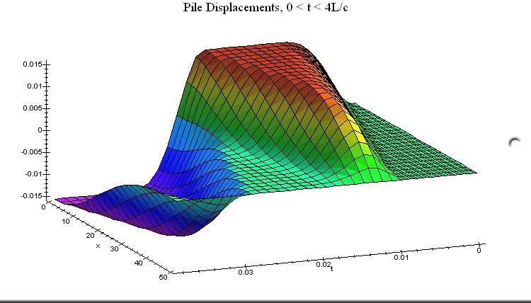
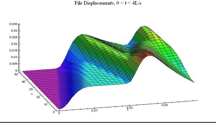
40 Finite Element Solution of Wave Equation
41 Deflection Curves

42 Displacement-Time Relationship Pile Head Pile Toe Time from Impact

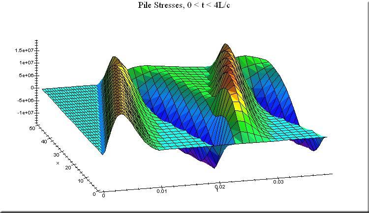
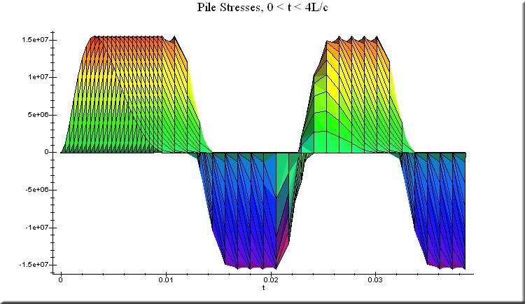
43 Stress-Time Relationship Pile Head Pile Toe Time from Impact

44 Pile Integrity Testing Hammer: Instrumented for TRM Accelerometer PILE INTEGRITY TESTER Pulse Echo: Velocity vs Time Transient Response: Mobility vs Frequency

45 Pile Integrity Testing Fast, Inexpensive Mobile equipment, minimum site support Test many or even all piles on site No advance planning required Minimal pile surface preparation Finds major defects

46 Better solution is Prevention defect Bad Pile Good Pile input toe


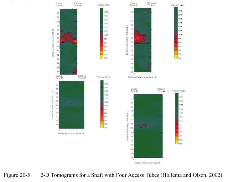
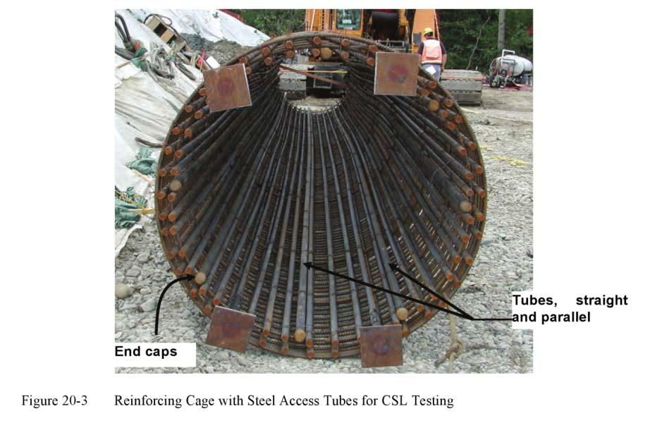
47 Crosshole Methods Crosshole Acoustic Logging Crosshole Tomography


48 Statnamic Tests
49 Statnamic Device and Principles Controlled explosion detonated; loads the pile over longer period of time than impact dynamic testing Upward thrust transferred to reaction weights Laser sensor records deflections; load cell records loads
50 Typical Statnamic Force- Time Curves Force, kn -100 Load (kn) Deflection, m Deflection (m) Time, sec
51 Typical Statnamic Load- Deflection Curves Total Force Static Force Displacement (m) Unloading Point Load (kn) Total Force less inertial force
52 Statnamic Advantages and Disadvantages Advantages Much faster and simpler than static load testing Does not require a pile hammer as high-strain dynamic testing does Especially applicable to drilled shafts and other bored piles Disadvantages Does not give a clear picture of the distribution of capacity between the shaft and the toe Technique not entirely developed for clay (high dampening) soils
53 Questions
Interpretation of Pile Integrity Test (PIT) Results
 Results") Annual Transactions of IESL, pp. 78-84, 26 The Institution of Engineers, Sri Lanka Interpretation of Pile Integrity Test (PIT) Results H. S. Thilakasiri Abstract: A defect present in a pile will severely
Annual Transactions of IESL, pp. 78-84, 26 The Institution of Engineers, Sri Lanka Interpretation of Pile Integrity Test (PIT) Results H. S. Thilakasiri Abstract: A defect present in a pile will severely
BACKGROUND AND INTRODUCTION
 WAVE MECHANICS As applied to pile testing 1 BACKGROUND AND INTRODUCTION Wave Mechanics 2 1 HISTORIC TOOLS AND MATERIALS Timber piles Drop Hammers 10 Days for the Romans to build the bridge over the Rhine
Lesson 25. Static Pile Load Testing, O-cell, and Statnamic. Reference Manual Chapter 18
 Lesson 25 Static Pile Load Testing, O-cell, and Statnamic Reference Manual Chapter 18 STATIC LOAD TESTING Most accurate method to determine static pile capacity Perform at design or construction stage
CAPWAP Introduction. 2016, Pile Dynamics, Inc. CAPWAP is a registered trademark of Pile Dynamics, Inc. Load (kn) Displacement (mm) Pile Top Bottom
 Displacement (mm) Pile Top Bottom") CAPWAP Introduction Load (kn) 0.0 1000.0 2000.0 3000.0 4000.0 0.00 Pile Top Bottom Displacement (mm) 5.00 10.00 Ru = Rs = Rb = Dy = Dx = 3425.2 kn 1458.6 kn 1966.6 kn 18.8 mm 18.8 mm 15.00 20.00 2016,
CAPWAP Introduction Load (kn) 0.0 1000.0 2000.0 3000.0 4000.0 0.00 Pile Top Bottom Displacement (mm) 5.00 10.00 Ru = Rs = Rb = Dy = Dx = 3425.2 kn 1458.6 kn 1966.6 kn 18.8 mm 18.8 mm 15.00 20.00 2016,
PDA Workshop: Stresses, Integrity, Energy and Capacity
 PDA Workshop: Stresses, Integrity, Energy and Capacity Ir Richard C L Yu IEM 2 Sep 2013 Dynamic Pile Monitoring For each blow determine Pile driving stresses Pile integrity Hammer performance Capacity
Understanding Dynamic Pile Testing and Driveability
 008-015 understand dynamic 5/30/06 5:10 PM Page 8 Understanding Dynamic Pile Testing and Driveability... By: Engr. Dr Sam Ming Tuck MIEM, P.Eng INTRODUCTION Traditionally, piles are static load tested
Verification of Signal Matching Analysis of Pile Driving Using a Finite Difference Based Continuum Numerical Method
 Verification of Signal Matching Analysis of Pile Driving Using a Finite Difference Based Continuum Numerical Method Shahram Feizee Masouleh 1, Kazem Fakharian 1,* Received 2 September 27; accepted 9 June
CAPWAP rules Important!
 CAPWAP rules Important! Unit friction < 4 ksf (200 kpa ) for most soils QT (+TG) < Dmax, toe to assure activation QS < 0.2 inch (5 mm ) usually 0.1 inch; 2.5 mm SS, ST < 0.4 s/ft (1.3 s/m ) if higher,
Congreso Internacional de Fundaciones Profundas de Bolivia Santa Cruz, Bolivia, 12 al 15 de Mayo de 2015 Day 1: Software Demonstrations
 Applications of Stress Wave Theory to Deep Foundations with an Emphasis on The Wave Equation (GRLWEAP) Congreso Internacional de Fundaciones Profundas de Bolivia Santa Cruz, Bolivia, 12 al 15 de Mayo de
Deep Foundations 2. Load Capacity of a Single Pile
 Deep Foundations 2 Load Capacity of a Single Pile All calculations of pile capacity are approximate because it is almost impossible to account for the variability of soil types and the differences in the
This document downloaded from vulcanhammer.net vulcanhammer.info Chet Aero Marine
 This document downloaded from vulcanhammer.net vulcanhammer.info Chet Aero Marine Don t forget to visit our companion site http://www.vulcanhammer.org Use subject to the terms and conditions of the respective
vulcanhammer.info the website about Vulcan Iron Works Inc. and the pile driving equipment it manufactured Terms and Conditions of Use:
 this document downloaded from vulcanhammer.info the website about Vulcan Iron Works Inc. and the pile driving equipment it manufactured Terms and Conditions of Use: All of the information, data and computer
Improving site specific modified driving formulae using high frequency displacement monitoring
 Proc. 20 th NZGS Geotechnical Symposium. Eds. GJ Alexander & CY Chin, Napier Improving site specific modified driving formulae using high frequency displacement monitoring R Damen Brian Perry Civil, Auckland,
vulcanhammer.info the website about Vulcan Iron Works Inc. and the pile driving equipment it manufactured Terms and Conditions of Use:
 this document downloaded from vulcanhammer.info the website about Vulcan Iron Works Inc. and the pile driving equipment it manufactured Terms and Conditions of Use: All of the information, data and computer
INCREASE IN PILE CAPACITY WITH TIME IN MISSOURI RIVER ALLUVIUM
 INCREASE IN PILE CAPACITY WITH TIME IN MISSOURI RIVER ALLUVIUM Paul J. Axtell Jacob W. Owen Scott D. Vollink U.S. Army Corps of Engineers U.S. Army Corps of Engineers U.S. Army Corps of Engineers Kansas
LOAD RESISTANCE FACTOR DESIGN (LRFD) FOR DRIVEN PILES BASED ON DYNAMIC METHODS WITH ASSESSMENT OF SKIN AND TIP RESISTANCE FROM PDA SIGNALS
 FOR DRIVEN PILES BASED ON DYNAMIC METHODS WITH ASSESSMENT OF SKIN AND TIP RESISTANCE FROM PDA SIGNALS") LOAD RESISTANCE FACTOR DESIGN (LRFD) FOR DRIVEN PILES BASED ON DYNAMIC METHODS WITH ASSESSMENT OF SKIN AND TIP RESISTANCE FROM PDA SIGNALS By ARIEL PEREZ PEREZ A THESIS PRESENTED TO THE GRADUATE SCHOOL
LOAD RESISTANCE FACTOR DESIGN (LRFD) FOR DRIVEN PILES BASED ON DYNAMIC METHODS WITH ASSESSMENT OF SKIN AND TIP RESISTANCE FROM PDA SIGNALS By ARIEL PEREZ PEREZ A THESIS PRESENTED TO THE GRADUATE SCHOOL
Maximum Envelope of Lateral Resistance through Dynamic Increasing Energy Test in Piles
 Maximum Envelope of Lateral Resistance through Dynamic Increasing Energy Test in Piles R.M. Valverde, F. Massad Abstract. The traditional dynamic load test, based on the one-dimensional wave propagation
vulcanhammer.info the website about Vulcan Iron Works Inc. and the pile driving equipment it manufactured Terms and Conditions of Use:
 this document downloaded from vulcanhammer.info the website about Vulcan Iron Works Inc. and the pile driving equipment it manufactured Terms and Conditions of Use: All of the information, data and computer
INTRODUCTION TO STATIC ANALYSIS PDPI 2013
 INTRODUCTION TO STATIC ANALYSIS PDPI 2013 What is Pile Capacity? When we load a pile until IT Fails what is IT Strength Considerations Two Failure Modes 1. Pile structural failure controlled by allowable
Additional Pile Design Considerations
 Additional Pile Design Considerations PDCA 2015 Professor Driven Pile Institute Patrick Hannigan GRL Engineers, Inc. What Are Additional Pile Design Considerations? Time Dependent Soil Strength Changes
Standard Test Method for High-Strain Dynamic Testing of Deep Foundations 1
 Designation: D4945 12 Standard Test Method for High-Strain Dynamic Testing of Deep Foundations 1 This standard is issued under the fixed designation D4945; the number immediately following the designation
Literature review Quasi-static and Dynamic pile load tests
 Literature review Quasi-static and Dynamic pile load tests --------N.Q.HUY-------- Table of contents: I. Introduction.3 II. Quasi static pile load test methods...4 2.1. Quasi static pile load test procedures
This document downloaded from vulcanhammer.net vulcanhammer.info Chet Aero Marine
 This document downloaded from vulcanhammer.net vulcanhammer.info Chet Aero Marine Don t forget to visit our companion site http://www.vulcanhammer.org Use subject to the terms and conditions of the respective
EQUIVALENT FRACTURE ENERGY CONCEPT FOR DYNAMIC RESPONSE ANALYSIS OF PROTOTYPE RC GIRDERS
 EQUIVALENT FRACTURE ENERGY CONCEPT FOR DYNAMIC RESPONSE ANALYSIS OF PROTOTYPE RC GIRDERS Abdul Qadir Bhatti 1, Norimitsu Kishi 2 and Khaliq U Rehman Shad 3 1 Assistant Professor, Dept. of Structural Engineering,
Impact. m k. Natural Period of Vibration τ. Static load Gray area Impact load t > 3 τ. Absorbing energy. Carrying loads
 Impact also called shock, sudden or impulsive loading driving a nail with a hammer, automobile collisions. dashpot a) Rapidly moving vehicles crossing a bridge To distinguish: b) Suddenly applied c) Direct
NON-DESTRUCTIVE EVALUATION METHODS FOR COMPOSITE PILES
 NON-DESTRUCTIVE EVALUATION METHODS FOR COMPOSITE PILES John F. Davila Graduate Research Assistant 2006 URI-UPRM SUMMER INTERNSHIP RESEARCH PROGRAM Kingstown, RI July 29 of 2006 PRESENTATION OUTLINE Introduction
Solid Mechanics Homework Answers
 Name: Date: Solid Mechanics Homework nswers Please show all of your work, including which equations you are using, and circle your final answer. Be sure to include the units in your answers. 1. The yield
five Mechanics of Materials 1 ARCHITECTURAL STRUCTURES: FORM, BEHAVIOR, AND DESIGN DR. ANNE NICHOLS SUMMER 2017 lecture
 ARCHITECTURAL STRUCTURES: FORM, BEHAVIOR, AND DESIGN DR. ANNE NICHOLS SUMMER 2017 lecture five mechanics www.carttalk.com of materials Mechanics of Materials 1 Mechanics of Materials MECHANICS MATERIALS
Discussion: behaviour of jacked and driven piles in sandy soil
 Title Discussion: behaviour of jacked and driven piles in sandy soil Author(s) Yang, J; Tham, LG; Lee, PKK; Chan, ST; Yu, F Citation Géotechnique, 27, v. 7 n., p. 47-478 Issued Date 27 URL http://hdl.handle.net/1722/7161
Back-Calculation of Winkler Foundation Parameters for Dynamic Analysis of Piles from Field Test Data
 Back-Calculation of Winkler Foundation Parameters for Dynamic Analysis of Piles from Field Test Data ABSTRACT A. (Rajah) Anandarajah, Jigang Zhang and G. Gnanaranjan Department of Civil Engineering Johns
Comparisons of rapid load test, dynamic load test and static load test on driven piles
 Comparisons of rapid load test, dynamic load test and static load test on driven piles Bamrungwong, C., Chaisukhang, J. & Janmonta, K. Department of Rural Roads, Thailand Kitiyodom, P. Geotechnical & Foundation
Numerical Modelling of Dynamic Earth Force Transmission to Underground Structures
 Numerical Modelling of Dynamic Earth Force Transmission to Underground Structures N. Kodama Waseda Institute for Advanced Study, Waseda University, Japan K. Komiya Chiba Institute of Technology, Japan
APPENDIX A - COMPUTER PROGRAM INPUT DATA. NCARDS = Total number of identification cards to be read, including Card 1 (Maximum of 8 cards).
.") APPENDIX A - COMPUTER PROGRAM INPUT DATA Introduction The following section lists the required information necessary to perform an analysis using the wave equation computer program. A detailed discussion
APPENDIX A - COMPUTER PROGRAM INPUT DATA Introduction The following section lists the required information necessary to perform an analysis using the wave equation computer program. A detailed discussion
Special edition paper
 Development of New Aseismatic Structure Using Escalators Kazunori Sasaki* Atsushi Hayashi* Hajime Yoshida** Toru Masuda* Aseismatic reinforcement work is often carried out in parallel with improvement
RAPID PLATE LOAD TESTS ON BEARING STRATUM OF A BUILDING FOUNDATION
 152 RAPID PLATE LOAD TESTS ON BEARING STRATUM OF A BUILDING FOUNDATION H. NEMOTO and H. SAKIHAMA ANDO Corporation, 1-19-61 Ooi-chuo, Fujimino City, Saitama, Japan fvgv182@mb.infoweb.ne.jp Y. NAKASHIMA
Lecture 19. Measurement of Solid-Mechanical Quantities (Chapter 8) Measuring Strain Measuring Displacement Measuring Linear Velocity
 Measuring Strain Measuring Displacement Measuring Linear Velocity") MECH 373 Instrumentation and Measurements Lecture 19 Measurement of Solid-Mechanical Quantities (Chapter 8) Measuring Strain Measuring Displacement Measuring Linear Velocity Measuring Accepleration and
MECH 373 Instrumentation and Measurements Lecture 19 Measurement of Solid-Mechanical Quantities (Chapter 8) Measuring Strain Measuring Displacement Measuring Linear Velocity Measuring Accepleration and
MATERIALS FOR CIVIL AND CONSTRUCTION ENGINEERS
 MATERIALS FOR CIVIL AND CONSTRUCTION ENGINEERS 3 rd Edition Michael S. Mamlouk Arizona State University John P. Zaniewski West Virginia University Solution Manual FOREWORD This solution manual includes
S E C T I O N 1 2 P R O D U C T S E L E C T I O N G U I D E - H E L I C A L S C R E W P I L E F O U N D A T I O N S
 1. P R O D U C T S E L E C T I O N G U I D E - H E L I C A L S C R E W P I L E F O U N D A T I O N S Helical foundation pile includes a lead and extension(s). The lead section is made of a central steel
Neutral Plane Method for Drag Force of Deep Foundations and the AASHTO LRFD Bridge Design Specifications
 Neutral Plane Method for Drag Force of Deep Foundations and the AASHTO LRFD Bridge Design Specifications Timothy C. Siegel, P.E., G.E., D.GE Dan Brown and Associates, PC, Knoxville, Tennessee USA Rich
Presented by: Civil Engineering Academy
 Presented by: Civil Engineering Academy Structural Design and Material Properties of Steel Presented by: Civil Engineering Academy Advantages 1. High strength per unit length resulting in smaller dead
CPT Guide 5 th Edition. CPT Applications - Deep Foundations. Gregg Drilling & Testing, Inc. Dr. Peter K. Robertson Webinar # /2/2013
 Gregg Drilling & Testing, Inc. Site Investigation Experts CPT Applications - Deep Foundations Dr. Peter K. Robertson Webinar #6 2013 CPT Guide 5 th Edition Robertson & Cabal (Robertson) 5 th Edition 2012
Bored Sockets in weathered Basalt
 Bored Sockets in weathered Basalt L. Maertens Manager Engineering Department Besix, Belgium Associate Professor Catholic University Leuven Keywords: sockets, open-end piles, tensile piles, basalt ABSTRACT:
[5] Stress and Strain
![[5] Stress and Strain](/thumbs/95/123344550.jpg "[5] Stress and Strain") [5] Stress and Strain Page 1 of 34 [5] Stress and Strain [5.1] Internal Stress of Solids [5.2] Design of Simple Connections (will not be covered in class) [5.3] Deformation and Strain [5.4] Hooke s Law
[5] Stress and Strain Page 1 of 34 [5] Stress and Strain [5.1] Internal Stress of Solids [5.2] Design of Simple Connections (will not be covered in class) [5.3] Deformation and Strain [5.4] Hooke s Law
IMPACT RESPONSE ANALYSIS OF LARGE SCALE RC GIRDER WITH SAND CUSHION
 -Technical Paper- IMPACT RESPONSE ANALYSIS OF LARGE SCALE RC GIRDER WITH SAND CUSHION Abdul Qadir BHATTI *1, Norimitsu KISHI *2, Shin-ya OKADA *3 and Hisashi KONNO *4 ABSTRACT In order to establish a proper
TIME-DEPENDENT BEHAVIOR OF PILE UNDER LATERAL LOAD USING THE BOUNDING SURFACE MODEL
 TIME-DEPENDENT BEHAVIOR OF PILE UNDER LATERAL LOAD USING THE BOUNDING SURFACE MODEL Qassun S. Mohammed Shafiqu and Maarib M. Ahmed Al-Sammaraey Department of Civil Engineering, Nahrain University, Iraq
This document downloaded from vulcanhammer.net vulcanhammer.info Chet Aero Marine
 This document downloaded from vulcanhammer.net vulcanhammer.info Chet Aero Marine Don t forget to visit our companion site http://www.vulcanhammer.org Use subject to the terms and conditions of the respective
Use of Ultra-High Performance Concrete in Geotechnical and Substructure Applications
 Use of Ultra-High Performance Concrete in Geotechnical and Substructure Applications i PI: Muhannad Suleiman Co-PI: Sri Sritharan Graduate Research Assistant: Thomas L. Vande Voort January 13, 29 IOWA
Model tests and FE-modelling of dynamic soil-structure interaction
 Shock and Vibration 19 (2012) 1061 1069 1061 DOI 10.3233/SAV-2012-0712 IOS Press Model tests and FE-modelling of dynamic soil-structure interaction N. Kodama a, * and K. Komiya b a Waseda Institute for
Seismic Pushover Analysis Using AASHTO Guide Specifications for LRFD Seismic Bridge Design
 Seismic Pushover Analysis Using AASHTO Guide Specifications for LRFD Seismic Bridge Design Elmer E. Marx, Alaska Department of Transportation and Public Facilities Michael Keever, California Department
PILE SETUP LA-1 EXPERIENCE. Ching-Nien Tsai, P.E.
 PILE SETUP LA-1 EXPERIENCE Ching-Nien Tsai, P.E. Bayou Lafourche Mississippi River GEOTECHNICAL INVESTIGATION PROGRAM 102 CPT soundings Depths from 100 feet to 200 feet 118 borings Depths from
Drilled Shaft Foundations in Limestone. Dan Brown, P.E., Ph.D. Dan Brown and Associates
 Drilled Shaft Foundations in Limestone Dan Brown, P.E., Ph.D. Dan Brown and Associates Foundation Engineering How we teach our students Fundamental understanding of soil and rock behavior (good!) Focus
LRFD GEOTECHNICAL IMPLEMENTATION
 LRFD GEOTECHNICAL IMPLEMENTATION Ching-Nien Tsai, P.E. LADOTD Pavement and Geotechnical Services In Conjunction with LTRC WHY LRFD FHWA deadline - October 2007 LRFD is a better method Risk is quantified
MECE 3321 MECHANICS OF SOLIDS CHAPTER 3
 MECE 3321 MECHANICS OF SOLIDS CHAPTER 3 Samantha Ramirez TENSION AND COMPRESSION TESTS Tension and compression tests are used primarily to determine the relationship between σ avg and ε avg in any material.
Axially Loaded Piles
 Axially Loaded Piles 1 t- Curve Method using Finite Element Analysis The stress-strain relationship for an axially loaded pile can be described through three loading mechanisms: axial deformation in the
Ground vibrations induced by impact pile driving.
 Ground vibrations induced by impact pile driving. Massarsch, K.R., and Fellenius, B.H., 28. Ground vibrations induced by impact pile driving. The Sixth International Conference on Case Histories in Geotechnical
two structural analysis (statics & mechanics) APPLIED ACHITECTURAL STRUCTURES: DR. ANNE NICHOLS SPRING 2017 lecture STRUCTURAL ANALYSIS AND SYSTEMS
 APPLIED ACHITECTURAL STRUCTURES: DR. ANNE NICHOLS SPRING 2017 lecture STRUCTURAL ANALYSIS AND SYSTEMS") APPLIED ACHITECTURAL STRUCTURES: STRUCTURAL ANALYSIS AND SYSTEMS DR. ANNE NICHOLS SPRING 2017 lecture two structural analysis (statics & mechanics) Analysis 1 Structural Requirements strength serviceability
APPLIED ACHITECTURAL STRUCTURES: STRUCTURAL ANALYSIS AND SYSTEMS DR. ANNE NICHOLS SPRING 2017 lecture two structural analysis (statics & mechanics) Analysis 1 Structural Requirements strength serviceability
MODELING SLAB-COLUMN CONNECTIONS REINFORCED WITH GFRP UNDER LOCALIZED IMPACT
 MODELING SLAB-COLUMN CONNECTIONS REINFORCED WITH GFRP UNDER LOCALIZED IMPACT QI ZHANG and AMGAD HUSSEIN Faculty of Engineering, Memorial University of Newfoundland St. John s, Newfoundland, Canada, A1B
Experiment Two (2) Torsional testing of Circular Shafts
 Torsional testing of Circular Shafts") Experiment Two (2) Torsional testing of Circular Shafts Introduction: Torsion occurs when any shaft is subjected to a torque. This is true whether the shaft is rotating (such as drive shafts on engines,
Experiment Two (2) Torsional testing of Circular Shafts Introduction: Torsion occurs when any shaft is subjected to a torque. This is true whether the shaft is rotating (such as drive shafts on engines,
CE 221: MECHANICS OF SOLIDS I CHAPTER 1: STRESS. Dr. Krisada Chaiyasarn Department of Civil Engineering, Faculty of Engineering Thammasat university
 CE 221: MECHANICS OF SOLIDS I CHAPTER 1: STRESS By Dr. Krisada Chaiyasarn Department of Civil Engineering, Faculty of Engineering Thammasat university Agenda Introduction to your lecturer Introduction
Feasibility of dynamic test methods in classification of damaged bridges
 Feasibility of dynamic test methods in classification of damaged bridges Flavio Galanti, PhD, MSc., Felieke van Duin, MSc. TNO Built Environment and Geosciences, P.O. Box 49, 26 AA, Delft, The Netherlands.
Calibration of Resistance Factors for Driven Piles using Static and Dynamic Tests
 University of Arkansas, Fayetteville ScholarWorks@UARK Theses and Dissertations 12-2014 Calibration of Resistance Factors for Driven Piles using Static and Dynamic Tests Deshinka A. Bostwick University
EVALUATION OF LOAD TESTS FOR DRIVEN PILES FOR THE ALABAMA DEPARTMENT OF TRANSPORTATION. Jacob Wayne Hill
 EVALUATION OF LOAD TESTS FOR DRIVEN PILES FOR THE ALABAMA DEPARTMENT OF TRANSPORTATION Except where reference is made to the work of others, the work described in this thesis is my own or was done in collaboration
The science of elasticity
 The science of elasticity In 1676 Hooke realized that 1.Every kind of solid changes shape when a mechanical force acts on it. 2.It is this change of shape which enables the solid to supply the reaction
1.103 CIVIL ENGINEERING MATERIALS LABORATORY (1-2-3) Dr. J.T. Germaine Spring 2004 LABORATORY ASSIGNMENT NUMBER 6
 Dr. J.T. Germaine Spring 2004 LABORATORY ASSIGNMENT NUMBER 6") 1.103 CIVIL ENGINEERING MATERIALS LABORATORY (1-2-3) Dr. J.T. Germaine MIT Spring 2004 LABORATORY ASSIGNMENT NUMBER 6 COMPRESSION TESTING AND ANISOTROPY OF WOOD Purpose: Reading: During this laboratory
1.103 CIVIL ENGINEERING MATERIALS LABORATORY (1-2-3) Dr. J.T. Germaine MIT Spring 2004 LABORATORY ASSIGNMENT NUMBER 6 COMPRESSION TESTING AND ANISOTROPY OF WOOD Purpose: Reading: During this laboratory
Chapter Two: Mechanical Properties of materials
 Chapter Two: Mechanical Properties of materials Time : 16 Hours An important consideration in the choice of a material is the way it behave when subjected to force. The mechanical properties of a material
Implementation of Laterally Loaded Piles in Multi-Layer Soils
 Implementation of Laterally Loaded Piles in Multi-Layer Soils JTRP SPR- 3261 Final SAC meeting SAC members Mir Zaheer and Keith Hoernschemeyer Purdue University Introduction Analysis developed for the
THE STRUCTURAL DESIGN OF PILE FOUNDATIONS BASED ON LRFD FOR JAPANESE HIGHWAYS
 THE STRUCTURAL DESIGN OF PILE FOUNDATIONS BASED ON LRFD FOR JAPANESE HIGHWAYS Hideaki Nishida 1,Toshiaki Nanazawa 2, Masahiro Shirato 3, Tetsuya Kohno 4, and Mitsuaki Kitaura 5 Abstract One of the motivations
Dynamic Pile Testing ASTM D4945
 Dynamic Pile Testing ASTM D4945 Pile Driving Analyzer Garland Likins, Pile Dynamics, Inc. 2011 PDCA Professor s Institute Why test driven piles? Public assured of safe foundation (bridges, buildings, etc.)
Comparison of Static and Dynamic Pile Load Tests at Thi Vai International Port in Viet Nam
 Comparison of Static and Dynamic Pile Load Tests at Thi Vai International Port in Viet Nam Le Phan Ta, Ph.D student, Graduate School of Kanazawa University, Japan (HCMC University of Architecture, Viet
ON THE PREDICTION OF EXPERIMENTAL RESULTS FROM TWO PILE TESTS UNDER FORCED VIBRATIONS
 Transactions, SMiRT-24 ON THE PREDICTION OF EXPERIMENTAL RESULTS FROM TWO PILE TESTS UNDER FORCED VIBRATIONS 1 Principal Engineer, MTR & Associates, USA INTRODUCTION Mansour Tabatabaie 1 Dynamic response
VMS-GeoMil. Background
 Background When using a drilling rig for cone penetration testing, a mechanical clamp can be mounted to the drilling head (by means of a special transition piece). The depth than can be achieved depends
Pre-failure Deformability of Geomaterials. Hsin-yu Shan Dept. of Civil Engineering National Chiao Tung University
 Pre-failure Deformability of Geomaterials Hsin-yu Shan Dept. of Civil Engineering National Chiao Tung University Strain Levels Strain at failure Sand Clay Rock Distribution of strain of soil in the field
Guidelines on Foundation Loading and Deformation Due to Liquefaction Induced Lateral Spreading
 Guidelines on Foundation Loading and Deformation Due to Liquefaction Induced Lateral Spreading February, 2011 1 INTRODUCTION Past earthquakes offer many examples of bridges that either collapsed or incurred
This document downloaded from vulcanhammer.net vulcanhammer.info Chet Aero Marine
 This document downloaded from vulcanhammer.net vulcanhammer.info Chet Aero Marine Don t forget to visit our companion site http://www.vulcanhammer.org Use subject to the terms and conditions of the respective
Improvement of Low Strain Pile Integrity Test
 Improvement of Low Strain Pile Integrity Test Wenzhang Luo 1, Fan Chen 2, and Junling Hu 1 1 Deparment of Mechanical Engineering, University of Bridgeport, Bridgeport, CT 06604 2 National Center for Quality
Mechanics of Materials Primer
 Mechanics of Materials rimer Notation: A = area (net = with holes, bearing = in contact, etc...) b = total width of material at a horizontal section d = diameter of a hole D = symbol for diameter E = modulus
ROLLER BEARING FAILURES IN REDUCTION GEAR CAUSED BY INADEQUATE DAMPING BY ELASTIC COUPLINGS FOR LOW ORDER EXCITATIONS
 ROLLER BEARIG FAILURES I REDUCTIO GEAR CAUSED BY IADEQUATE DAMPIG BY ELASTIC COUPLIGS FOR LOW ORDER EXCITATIOS ~by Herbert Roeser, Trans Marine Propulsion Systems, Inc. Seattle Flexible couplings provide
Sean Carey Tafe No Lab Report: Hounsfield Tension Test
 Sean Carey Tafe No. 366851615 Lab Report: Hounsfield Tension Test August 2012 The Hounsfield Tester The Hounsfield Tester can do a variety of tests on a small test-piece. It is mostly used for tensile
Back Calculation of Rock Mass Modulus using Finite Element Code (COMSOL)
") Back Calculation of Rock Mass Modulus using Finite Element Code (COMSOL) Amirreza Ghasemi 1. Introduction Deformability is recognized as one of the most important parameters governing the behavior of rock
Back Calculation of Rock Mass Modulus using Finite Element Code (COMSOL) Amirreza Ghasemi 1. Introduction Deformability is recognized as one of the most important parameters governing the behavior of rock
vulcanhammer.info the website about Vulcan Iron Works Inc. and the pile driving equipment it manufactured Terms and Conditions of Use:
 this document downloaded from vulcanhammer.info the website about Vulcan Iron Works Inc. and the pile driving equipment it manufactured Terms and Conditions of Use: All of the information, data and computer
COEFFICIENT OF DYNAMIC HORIZONTAL SUBGRADE REACTION OF PILE FOUNDATIONS ON PROBLEMATIC GROUND IN HOKKAIDO Hirofumi Fukushima 1
 COEFFICIENT OF DYNAMIC HORIZONTAL SUBGRADE REACTION OF PILE FOUNDATIONS ON PROBLEMATIC GROUND IN HOKKAIDO Hirofumi Fukushima 1 Abstract In this study, static loading tests and dynamic shaking tests of
Lateral Resistance of Short Rock Sockets in Weak Rock: a Case History. Text word count: 4140 Number of figures and tables: 13
 Lateral Resistance of Short Rock Sockets in Weak Rock: a Case History Text word count: Number of figures and tables: 1 Robert L. Parsons PhD, P.E (Corresponding Author) Associate Professor Department of
Civil Engineering Design (1) Design of Reinforced Concrete Columns 2006/7
 Design of Reinforced Concrete Columns 2006/7") Civil Engineering Design (1) Design of Reinforced Concrete Columns 2006/7 Dr. Colin Caprani, Chartered Engineer 1 Contents 1. Introduction... 3 1.1 Background... 3 1.2 Failure Modes... 5 1.3 Design Aspects...
Civil Engineering Design (1) Design of Reinforced Concrete Columns 2006/7 Dr. Colin Caprani, Chartered Engineer 1 Contents 1. Introduction... 3 1.1 Background... 3 1.2 Failure Modes... 5 1.3 Design Aspects...
Finite Element Modelling with Plastic Hinges
 01/02/2016 Marco Donà Finite Element Modelling with Plastic Hinges 1 Plastic hinge approach A plastic hinge represents a concentrated post-yield behaviour in one or more degrees of freedom. Hinges only
Stress Analysis Lecture 3 ME 276 Spring Dr./ Ahmed Mohamed Nagib Elmekawy
 Stress Analysis Lecture 3 ME 276 Spring 2017-2018 Dr./ Ahmed Mohamed Nagib Elmekawy Axial Stress 2 Beam under the action of two tensile forces 3 Beam under the action of two tensile forces 4 Shear Stress
Failure in Flexure. Introduction to Steel Design, Tensile Steel Members Modes of Failure & Effective Areas
 Introduction to Steel Design, Tensile Steel Members Modes of Failure & Effective Areas MORGAN STATE UNIVERSITY SCHOOL OF ARCHITECTURE AND PLANNING LECTURE VIII Dr. Jason E. Charalambides Failure in Flexure!
Chapter (3) Ultimate Bearing Capacity of Shallow Foundations
 Ultimate Bearing Capacity of Shallow Foundations") Chapter (3) Ultimate Bearing Capacity of Shallow Foundations Introduction To perform satisfactorily, shallow foundations must have two main characteristics: 1. They have to be safe against overall shear
Chapter (3) Ultimate Bearing Capacity of Shallow Foundations Introduction To perform satisfactorily, shallow foundations must have two main characteristics: 1. They have to be safe against overall shear
Verification of a Micropile Foundation
 Engineering manual No. 36 Update 02/2018 Verification of a Micropile Foundation Program: File: Pile Group Demo_manual_en_36.gsp The objective of this engineering manual is to explain the application of
Members Subjected to Torsional Loads
 Members Subjected to Torsional Loads Torsion of circular shafts Definition of Torsion: Consider a shaft rigidly clamped at one end and twisted at the other end by a torque T = F.d applied in a plane perpendicular
Numerical modelling of tension piles
 Numerical modelling of tension piles S. van Baars Ministry of Public Works, Utrecht, Netherlands W.J. van Niekerk Ballast Nedam Engineering, Amstelveen, Netherlands Keywords: tension piles, shaft friction,
Effective stress analysis of pile foundations in liquefiable soil
 Effective stress analysis of pile foundations in liquefiable soil H. J. Bowen, M. Cubrinovski University of Canterbury, Christchurch, New Zealand. M. E. Jacka Tonkin and Taylor Ltd., Christchurch, New
Liquefaction Induced Negative Skin Friction from Blast-induced Liquefaction Tests with Auger-cast Piles
 6 th International Conference on Earthquake Geotechnical Engineering 1-4 November 2015 Christchurch, New Zealand Liquefaction Induced Negative Skin Friction from Blast-induced Liquefaction Tests with Auger-cast
Assessment of Calculation Procedures for Piles in Clay based on Static Loading Tests Anders Hust Augustesen
 Assessment of Calculation Procedures for Piles in Clay based on Static Loading Tests By Anders Hust Augustesen 1 Agenda Presentation of calculation procedures Basis for the evaluation of the calculation
SOIL-STRUCTURE INTERACTION, WAVE PASSAGE EFFECTS AND ASSYMETRY IN NONLINEAR SOIL RESPONSE
 SOIL-STRUCTURE INTERACTION, WAVE PASSAGE EFFECTS AND ASSYMETRY IN NONLINEAR SOIL RESPONSE Mihailo D. Trifunac Civil Eng. Department University of Southern California, Los Angeles, CA E-mail: trifunac@usc.edu
Task 1 - Material Testing of Bionax Pipe and Joints
 Task 1 - Material Testing of Bionax Pipe and Joints Submitted to: Jeff Phillips Western Regional Engineer IPEX Management, Inc. 20460 Duncan Way Langley, BC, Canada V3A 7A3 Ph: 604-534-8631 Fax: 604-534-7616
Flexure: Behavior and Nominal Strength of Beam Sections
 4 5000 4000 (increased d ) (increased f (increased A s or f y ) c or b) Flexure: Behavior and Nominal Strength of Beam Sections Moment (kip-in.) 3000 2000 1000 0 0 (basic) (A s 0.5A s ) 0.0005 0.001 0.0015
Chapter (11) Pile Foundations
 Pile Foundations") Chapter (11) Introduction Piles are structural members that are made of steel, concrete, or timber. They are used to build pile foundations (classified as deep foundations) which cost more than shallow
Chapter (11) Introduction Piles are structural members that are made of steel, concrete, or timber. They are used to build pile foundations (classified as deep foundations) which cost more than shallow
Summary and Review of Part II of the Symposium on Pile Foundations
 Summary and Review of Part II of the Symposium on Pile Foundations G. A. LEONARDS, Purdue University PILE FOUNDATIONS share with cellular cofferdams the distinction of yielding most reluctantly to the
1/2. E c Part a The solution is identical for grade 40 and grade 60 reinforcement. P s f c n A s lbf. The steel carries 13.3 percent of the load
 1/2 3.1. A 16 20 in. column is made of the same concrete and reinforced with the same six No. 9 (No. 29) bars as the column in Examples 3.1 and 3.2, except t hat a steel with yield strength f y = 40 ksi
Study of Rotational Column with Plastic Hinge
 Study of Rotational Column with Plastic Hinge Presented by: Michael Long, Rice University Corey Bergad, Bates College REU Interns, SUNY at Buffalo Advisor: Andrei M. Reinhorn, Ph.D., P.E. Professor and