Implementation of Pile Setup in the LRFD Design of Driven Piles in Louisiana
|
|
|
- Michael Thornton
- 6 years ago
- Views:
Transcription
1 Implementation of Pile Setup in the LRFD Design of Driven Piles in Louisiana Md. Nafiul Haque (Ph.D. Candidate) Murad Y. Abu-Farsakh, Ph.D., P.E. March 1, 2016 Louisiana Transportation Conference

2 OUTLINE Objectives Brief Background Methodology Results and Analysis Analytical Models LRFD Calibration 2
3 OBJECTIVES Evaluate the time-dependant increase in pile capacity (or setup) for piles driven into Louisiana soils through conducting repeated static and dynamic field testing with time on full-scale instrumented test piles. Study the effect of soil type/properties, pile size, and their interaction on pile setup phenomenon. Develop analytical model(s) to estimate pile setup with time using typical soil properties. Incorporate setup into LRFD design of driven pile in Louisiana (calibrate setup resistance factor, f setup ). 3
.")

4 PILE SET-UP Pile resistance/capacity have been reported to usually increase with time, after end of pile driving (EOD). The increase in resistance/capacity after end of driving, is known as pile set-up. Set-up is observed both in cohesive (clayey) and non-cohesive (sandy-silty) soils. 4
5 Benefits of Incorporating Set-up in Design The implementation of pile set-up capacity in the design can result in significant cost savings through Shortening pile lengths Reducing pile cross-sectional area (using smaller-diameter/width piles) Smaller hammer to drive pile Reducing the number of piles Substantial cost will be saved for full project 5
6 MECHANISMS - Pile Set-Up Soil around the pile usually experiences plastic deformation and remolded during pile driving. Excess pore water pressure develops as the result of pile driving. After the completion of pile driving, a certain degree of excess pore water pressure dissipates at the soil-pile interface zone, usually resulting in an increase in pile resistance. Aging and Thixotropy also plays significant role in set-up. Fellenius, 2008 Result from Our Study 6
7 MECHANISMS - Pile Set-Up In cohesive soils, the induced excess pore water pressure may dissipate slowly due to low permeability and it takes days to dissipate. However, for noncohesive soils, the duration of dissipation of excess pore water pressure take several hours to several days due to high permeability. This dissipation phase plays the most significant role for the set-up phase / period or how long it will take for the completion of set-up. Clayey Soil Sandy Soil 7
8 EMPIRICAL MODELS The model that were developed earlier were mainly formed by regression analyses of limited data sets. The first model for pile set-up was proposed by Skov and Denver in Rt t R o = 1 + A log 10 t o R t : the ultimate pile capacity at time t after driving, R o : the ultimate pile capacity at time (Reference time) t o, A : a constant that depends on soil type and pile characteristics, t o : initial time (taken as the time to first restrike), Reference time 8
9 Resistance/Capacity Phase 1 A parameter R t Phase 2 R o Slope of the line, A Phase 3 t o log (t/t o ) t 9
10 Methodology Conduct Field Test Collect Data From Performed Old Set-up Studies Analyze Data For Individual Soil Layers Correlate Set-up of Individual Soil Layers with Soil Properties Develop Model LRFD Calibration 10
11 METHODOLOGY Field Projects Instrumented Test Piles (12 Test Piles) 1. Bayou Lacassine (3 Test Piles) 2. Bayou Zourie (1 Test Pile) 3. Bayou Bouef (1 Test Pile) 4. LA-1 (6 Test Piles) 5. Bayou Teche (1 Test Pile) 11
12 METHODOLOGY-FIELD PROJECTS 12
13 Depth (m) Depth (ft) SOIL INVESTIGATION Soil Type TN. SI. SA. BR. SA. SI. GR. & TN. SA GR. & TN. CL. SA. w/cl TN. SA. GR. Sandy CL. GR. SI. CL. GR. & BR. CL M.C.; L.L.; & P.I Liquid Limit Moisture Content Plasticity Index Particle Size Distribution (%) Clay Silt Sand Zhang and Tumay (1999) method S u (kpa) Coefficient of Probability of Consolidation (cmtip 2 /sec) Resistance, q t, (MPa) Soil Type(%) S u from UU PCPT Test-1 3 S u from CPT Minimum Test-2 6 Maximum Insitu 9 Test

14 Normalized Excess Pore Water Pressure ( u/ui) Normalized Excess Pore Water Pressure ( u/ui) Dissipation Tests to Calculate c v m m m m m m m m m m m 5.14 m 8.38 m 6.38 m m Time (sec) BL-TP Time (sec) BL-TP-3 Bayou Zourrie 14
15 METHODOLOGY-INSTRUMENTATION Sister bar Strain gauges Pressure cells Piezometers Multilevel Piezometers Clayey Sandy Clayey Sandy Sandy Clayey Soil Profile 15
16 Depth (ft) METHODOLOGY-INSTRUMENTATION OCR OCR from CPT OCR from Lab Tip Resistance, q t (MPa) Rf (%) Probability of Soil Type (%) " Always one pair of strain gauge was installed near top in order to calibrate the elastic G.L. modulus 8.0' Layer ' 28.0' 23 Sandy Clayey Clayey Clayey Layer ' Layer-3 5.0' Layer-4 5.0' Layer ' Layer-6 5.0' Layer-7 5.0' Layer-8 5.0' 12.0' B 14.0' B 10.0' B B B MP-1 MP-2 MP-3 B B B MP-4 MP-5 MP-6 B MP-7 MP-8 MP-9 One pair of strain gauge near tip in order to calculate the tip resistance 16
17 INSTRUMENTATION PLAN FOR TEST PILES 30" 30" G.L. G.L. 8.0' 8.0' Layer ' 28.0' Layer ' 28.0' Layer ' Layer-3 5.0' Layer-4 5.0' Layer ' Layer-6 5.0' Layer-7 5.0' Layer-8 5.0' TP-1 B B B Layer-2 4.0' Layer-3 8.0' MP-1 MP-2 MP ' B B B Layer-4 5.0' Layer-5 5.0' MP-4 MP-5 MP ' B B B Layer ' 10.0' MP-7 MP-8 MP-9 Layer ' 2.0' Layer-8 B B B MP-1 MP-2 MP-3 8.0' B B B MP-4 MP-5 MP ' B B B MP-7 MP-8 MP ' 7.0' TP-3 17


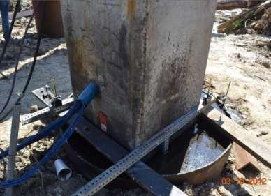
18 INSTRUMENTATION Sister bar strain gauges Sister bar strain gauges always installed in pairs- The average readings were taken in order to eliminate the effect bending stress during driving 18


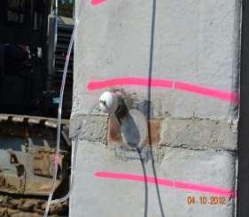
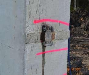
19 INSTRUMENTATION Geokon Model 4820 Pressure cell Piezometer Geokon Model 4500S Pressure cell & Piezometer 19


20 INSTRUMENTATION Installed in predefined depth Before Pouring Concrete After Pouring Concrete 20

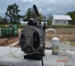
21 INSTRUMENTATION Saturated before driving Vacuum pump and peanut oil was used 21


22 INSTRUMENTATION Multilevel Piezometer Saturated before driving Installed with PVC pipe at predefined depth 22


23 INSTRUMENTATION All the wires were pulled out through a PVC pipe near the top of pile The wires were connected to a data logger system through a trench A data collection system composed of CR-1000, multiplexels and solar panel was there for six months 23


24 DRIVING AND LOAD TESTS Hammer PDA device Accelerometer and strain transducer 24

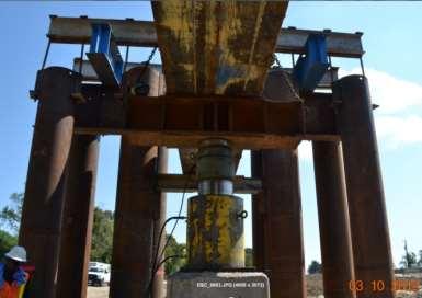
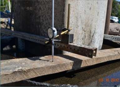
25 STATIC LOAD TESTS 25

26 BAYOU LACASSINE 26


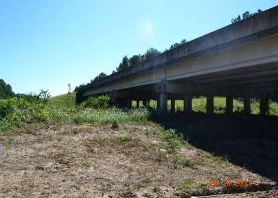
27 BAYOU LACASSINE The project was located in Lake Charles, Louisiana The test piles were monitored for 6 months. 3 dynamic load tests and 5 static load tests were conducted. TP-1 TP-2 TP-3 27
28 Depth (m) Depth (ft) DYNAMIC LOAD TEST Total Side Resistance (kips) Driving EOD 1st Restrike (0.5 hour) 2nd Restrike (1 day) 3rd Restrike (217 day) 217 days Total Side Resistance (kn) TP-1 Total Side Resistance (kips) Driving EOD 1st Restrike (1 hour) 2nd Restrike (1 day) 3rd Restrike (181 day) Total Side Resistance (kn) TP days
29 Settlement (mm) Settlement (inch) STATIC LOAD TEST 0 Load (kips) Load (kips) st SLT (13 days) 2nd SLT (53 days) 3rd SLT (127 days) 4th SLT (148 days) 5th SLT (208 days) 1 st SLT 5 th SLT. 1st SLT (15 days) 2nd SLT (29 days) 3rd SLT (93 days) 4th SLT (129 days) 5th SLT (175 days) 1 st SLT 5 th SLT Load (kn) TP Load (kn) TP-3 29
30 Set-Up Plots for Bayou Lacassine Set-up for TP-1 Set-up for TP-3 30
31 Set-Up for TP-1 Events Time from EOD Total Resistanc e Increas e from EOD Side Resistan ce Increas e from EOD Tip Resistan ce Increas e from EOD Set-up factor for Total Resistan ce Days kips % kips % kips % (R t /R o ) TP-1 EOD st RST nd RST SLT SLT SLT SLT SLT rd RST
32 Results-Bayou Zourrie 32
33 Pile Resistance, QR (kn) Pile Resistance,QR (kips) Set-up Results for Bayou Zourrie Events Time Side Resistance Tip Resistance Total Resistance kips % kips % kips % Driven /602-1 st Dynamic Load Test 1 hr / nd Dynamic Load Test 1 day / st Static Load Test 14 days 2 nd Static Load Test 30 days 3 rd Dynamic Load Test 78 days / R 2 = Time, t (Days) 33

34 LA-1 TP-2 TP-3 TP-4 TP-5 34

 BZ R s /R so 1.")
35 LA-1 Time Side Resistance, R s Events Set-up Hour kips Ratio s (R s /R so ) EOD st DLT nd DLT rd DLT th DLT th DLT th DLT th DLT Static Test For BL R s /R so 1.7 times (In 6 months) BZ R s /R so 1.8 times (In 3 months) Very soft soil 35


36 Set-Up for Bayou Teche and Bayou Bouef Bayou Teche Bayou Bouef R s /R so 1.9 times (In 32 days) R s /R so 3.8 times (In 716 days-almost 2 years) 36
 The result is consistent")

37 Pile Set-Up (Result of 12 Test Piles) The result is consistent with literature that set-up fits best with linear logarithmic of time 37
38 Percentage of Excess Pore Water Pressure Dissipation (%) Set-Up Process with Consolidation Behavior 0 2nd Restrike 1st SLT 2nd Restrike Installation of Load Frame 8.54 m deep m deep m deep m deep 3rd SLT 4th SLT 2nd SLT 5th SLT Time after EOD, t (Days) TP-1 Installation of Load Frame 8.54 m deep m deep m deep m deep Time after EOD, t (Days) TP-3 1st SLT 2nd SLT 3rd SLT 4th SLT 5th SLT Set-up continues for 127 days No set-up after 15 days 38


39 Set-Up Process with Consolidation Behavior By Layers Smaller amount of set-up or low rate of set-up as consolidation process finished earlier Higher amount or rate of set-up as consolidation process continued for longer period of time 39


40 Set-Up for Individual Soil Layers P = E x ξ x A Load-Strain Plot Tip Resistance Used to calculate the resistance of individual soil layers Modulus-Strain Plot Load Distribution Plot 40
41 Depth (m) Depth (m) Depth (ft) Depth (ft) CAPWAP ANALYSES Unit SIde Resistance (kpa) EOD BOR1 BOR2 BOR Unit Side Resistance (kpa) CAPWAP analyses for Bayou Zourrie Total Side Resistance (kips) EOD BOR1 BOR2 BOR Total Side Resistance (kn) CAPWAP analyses for LA-1 Test Pile 41

42 Depth (m) Soil Profile for Bayou Zourrie Depth (ft) Soil Type TN. SI. SA. BR. SA. SI. GR. & TN. SA GR. & TN. CL. SA. w/cl TN. SA. GR. Sandy CL. GR. SI. CL. GR. & BR. CL M.C.; L.L.; & P.I Liquid Limit Moisture Content Plasticity Index Particle Size Distribution (%) Clay Silt Sand Layer-1 Layer-2 Layer-3 Layer-4 Layer-5 Layer-6 S u (kpa) Coefficient of Probability of Consolidation (cmtip 2 /sec) Resistance, q t, (MPa) Soil Type(%) S u from UU PCPT Test-1 3 S u from CPT Minimum Test-2 6 Maximum Insitu 9 Test
43 Set-up Ratio of Side Resistance (f t /f o ) Set-Up in Clayey Soil layers Unit Side Resistance, f (kpa) Dissipation of Excess PWP (kpa) Unit Side Resistance, f (kpa) Excess PWP DLT SLT f t /f o = 0.26 log (t/t o ) + 1 R 2 = Time after EOD, t (Days) 20 Clayey Soil Layer of Bayou Lacassine Clayey Soil Layer of Bayou Lacassine Unit Side Resistance, f (ksf)2.20 DLT-Layer-1 SLT-Layer-1 DLT-Layer-6 SLT-Layer-6 DLT-Layer-7 SLT-Layer-7 f s /f so = 0.31 log (t/t o ) + 1 R 2 = 0.96 f s /f so = 0.37 log (t/t o ) + 1 R 2 = 0.70 f s /f so = 0.43 log (t/t o ) + 1 R 2 = Time, t (Days) Clayey Soil Layer of LA-1 site Time, t (Days) Unit Side Resistance, f (ksf)0.95 DLT-Layer-2 SLT-Layer-2 DLT-Layer-4 SLT-Layer-4 DLT-Layer-5 SLT-Layer-5 f s /f so = 0.40 log (t/t o ) + 1 R 2 = 0.99 f s /f so = 0.45 log (t/t o ) + 1 R 2 = 0.99 f s /f so = 0.51 log (t/t o ) + 1 R 2 = 0.96 Clayey Soil Layer of LA-1 site
44 Set-Up in Sandy Soil layers Unit Side Resistance, f (kpa) Unit Side Resistance, f (kpa) Sandy Soil Layer of Bayou Zourie Time, t (Days) Unit Side Resistance, f (ksf)2.80 DLT-Layer-2 SLT-Layer-2 SLT-Layer-5 SLT-Layer-5 DLT-Layer-8 f s /f so = 0.08 log (t/t o ) + 1 R 2 = 0.94 f s /f so = 0.07 log (t/t o ) + 1 R 2 = 0.76 f s /f so = 0.13 log (t/t o ) + 1 R 2 = Sandy Soil Layers of LA-1 site Sandy Soil Layer of Bayou Lacassine Time, t (Days) Unit Side Resistance, f (ksf)2.05 DLT-Layer-3 SLT-Layer-3 DLT-Layer-6 SLT-Layer-6 DLT-Layer-9 SLT-Layer-9 f s /f so = 0.20 log (t/t o ) + 1 R 2 = 0.97 f s /f so = 0.16 log (t/t o ) + 1 R 2 = 0.96 f s /f so = 0.12 log (t/t o ) + 1 R 2 = Sandy Soil Layers of LA-1 site 44
45 SUMMARY OF A 94 soil layers were first identified based on soil strata from 12 instrumented test piles. Clayey soil behavior was dominant in 70 soil layers. Sandy soil behavior was dominant in 24 soil layers. Set-up parameter A was back-calculated for all soil layers using unit side resistance (f s ). The maximum A for clayey soil layers was The average A for clayey soil layer was The maximum A for sandy soil layers was The average A for sandy soil layer was


46 EMPIRICAL MODEL 46
47 Steps Followed for Model Preparation Identify potential soil properties Find the correlation between soil properties and A parameter Develop the model with SAS Perform F test and t test to find the significance of the model as well the independent parameters Perform detail statistical analyses (Goodness of fit, COV, Correlation among the parameters, P seudo R 2 etc) Validate the model with non-instrumented pile (These were not used to develop the model) Verify the model with published case studies 47
 Overburden pressure/depth Pile size/width (r) Sensitivity (S t ) Corrected Cone Tip")
48 Undrained Shear Strength (S u ) Plasticity Index (PI) Over consolidation ratio (OCR) Coefficient of consolidation (c v ) Overburden pressure/depth Pile size/width (r) Sensitivity (S t ) Corrected Cone Tip Resistance (q t ) 48
49 EMPIRICAL MODELS Level-1 Including Undrained Shear Strength (S u ) Plasticity Index (PI) Level-2 Including Undrained Shear Strength (S u ) Plasticity Index (PI) Coefficient of Consolidation (c v ) Level-3 Including Undrained Shear Strength (S u ) Plasticity Index (PI) Coefficient of Consolidation (c v ) Sensitivity (S t ) 49
50 Clayey soil with high S u exhibited low set-up Clayey soil with low S u exhibited high set-up Clayey soil with low PI exhibited low set-up Clayey soil with high PI exhibited high set-up 50
51 Clayey soil with high c v exhibited low set-up Clayey soil with low c v exhibited high set-up OC clay exhibited low set-up NC clay exhibited high set-up 51
52 High sensitive clay exhibited higher set-up Low sensitive clay exhibited lower set-up 52
53 No strong correlation was observed in between depth and pile size with r 53
54 Final Developed Models A = 0.79 S u 1tsf PI A=f (PI, S u ) A = S u 1tsf log PI C v 0.01 in2 hour A=f (PI, S u, C v ) A = S u 1tsf log PI 100 C v 0.01 in2 hour S t A=f (PI, S u, C v, S t ) 54
55 EMPIRICAL MODEL Implementation Procedure 1. Define the soil layers along the length of the pile 2. Calculate the subsurface soil properties (i.e., S u, PI, OCR, c v, S t, q t ) 3. Evaluate f so of each soil layer from 1 st restrike (1 hr to 1 day). 4. Use the developed model to calculate f s at desired time (for clay) f s fso = 1 + [ 0.79 PI ] log t Su to 1 tsf R si (set-up) = f si (set-up ) x A si 5. Use a constant value of A = 0.15 set-up parameter (for sand) f s fso = log t to 6. R s (set-up) = R s1 (set-up) + R s2 (set-up) +..+ R sn (set-up) 55
56 LRFD CALIBRATION
57 LRFD CALIBRATION The limit state equation is g (R, Q) = R Q After considering set-up the above Equation can be rewritten as g (R, Q) = (R 14 +R set-up ) Q The limit state equation becomes ϕ 14 R 14 + ϕ set-up R set-up = γ DL Q DL + γ LL Q LL 57
58 LRFD CALIBRATION For Φ 14 By Abu-Farsakh et al. (2009) Resistance Factor (f14) and Efficiency Factor (f/l) for Louisiana Soil Design Method Monte Carlo FOSM FORM Simulation f 14 f14/l f 14 f 14 /l f 14 f 14 /l a-tomlinson Recommended Static method method and Nordlund method Schmertmann f 14 Direct CPT method LCPC/LCP De Ruiter and Beringen CPT average Dynamic CAPWAP (EOD) measurement CAPWAP (14 days BOR)
59 LRFD CALIBRATION *Set-up was predicted with the developed models. *Set-up was calculated or LRFD was calibrated for the resistance after 14 days for four different times days days days days (a) Comparison of (R 30 - R 14 ) for Level-1 (b) Comparison of (R 45 - R 14 ) for Level-1
60 LRFD CALIBRATION (c) Comparison of (R 60 - R 14 ) for Level-1 Summary Statistics R m /R p R p /R m Time Mean (λ R ) σ COV Mean (d) Comparison of (R 90 - R 14 ) for Level-1
61 Probability Density Function and Histogram R 30 - R 14 R 45 - R 14 R 60 - R 14 R 90 - R 14 61
62 LRFD CALIBRATION Reliability Calibration Methods: FOSM closed form solution ϕ setup = γ D.L. + γ L.L. Ҡ ϕ 14 α (1 + Ҡ) λ D.L. + λ L.L Ҡ λ R14 (γ ϕ D.L. + γ L.L. Ҡ) R setup 14 α = R 14 Q D.L. + Q L.L Ҡ = Q L.L. Q D.L. = FORM iterative procedure Monte Carlo Simulation (MCS) Method iterative procedure 62
63 CALIBRATION RESULTS R 30 - R 14 R 45 - R R 60 - R 14 R 90 - R
64 CALIBRATION RESULTS β T = 2.33 FOSM FORM MC Recommended Days Days Days Days Kam Ng (2013) Yang & Liang (2006) Overall Recommended = f setup = 0.35 D Q D L Q L f 14 R 14 f setup R setup 64
65 CONCLUSIONS Set-up study was conducted on 12 instrumented test piles of 5 different sites. Set-up was mainly exhibited by side resistance. The tip resistance was almost constant. Set-up was mainly attribute to the consolidation behavior. Amount of set-up and set-up rate increased significantly during consolidation phase. Very small amount of set-up was observed during aging period. Horizontal effective stress increased significantly during the consolidation period. Once the consolidation period was over, the amount of increase became slower. Set-up for individual soil layers was calculated with the aid of strain gauge. The set-up rate A for clayey soil layers was 0.31 and for sandy soil layers it was
66 Three models were developed A = 0.79 A = A = S u 1tsf S u 1tsf S u 1tsf PI PI log C v 0.01 in2 hour 0.44 PI 100 S t log CONCLUSIONS C v 0.01 in2 hour A= f(pi, S u ) [Lab Test] A= f(pi, S u, C v ) [Lab Test] A= f(pi, S u, C v, S t ) [Lab Test] Set-up rate can be processed to predict total set-up resistance. The recommended set-up factor is 0.35 for LRFD design. 66
67 Chen, Q., Haque, Md. N., Abu-Farsakh, M., and Fernandez, B. A. (2014). Field investigation of pile setup in mixed soil. Geotechnical Testing Journal, Vol. 37(2), pp Haque, Md. N., Abu-Farsakh, M., Chen, Q., and Zhang, Z. (2014). A case study on instrumenting and testing full scale test piles for evaluating set-up phenomenon. Journal of the Transportation Research Board No 2462, National Research Council, Washington, D.C., pp Haque, Md. N., Abu-Farsakh, M., Zhang, Z. and Okeil, A. (2016). Estimate pile set-up for individual soil layers and develop a model to estimate the increase in unit side resistance with time based on PCPT data. Journal of the Transportation Research Board, National Research Council, Washington, D.C. (In Press). Haque, Md. N., Chen, Q., Abu-Farsakh, M., and Tsai, C. (2014). Effects of pile size on set-up behavior of cohesive soils. In Proceedings of Geo-Congress- 2014: Geo-Characterization and Modeling for Sustainability, Technical Papers GSP 234, pp Haque, Md. N., Abu-Farsakh, M., and Chen, Q. (2015). Pile set-up for individual soil layers along instrumented test piles in clayey soil. In Proceedings of the 15 th Pan-American Conference on Soil Mechanics and Geotechnical Engineering (From fundamentals to applications in Geotechnics), November 15-18, Argentina, pp

")
68 ACKNOWLEDGEMENT LADOTD Geotechnical Department Louisiana Transportation Research Center (LTRC) 68
LRFD Calibration of Axially-Loaded Concrete Piles Driven into Louisiana Soils
 LRFD Calibration of Axially-Loaded Concrete Piles Driven into Louisiana Soils Louisiana Transportation Conference February 10, 2009 Sungmin Sean Yoon, Ph. D., P.E. (Presenter) Murad Abu-Farsakh, Ph. D.,
LRFD GEOTECHNICAL IMPLEMENTATION
 LRFD GEOTECHNICAL IMPLEMENTATION Ching-Nien Tsai, P.E. LADOTD Pavement and Geotechnical Services In Conjunction with LTRC WHY LRFD FHWA deadline - October 2007 LRFD is a better method Risk is quantified
LRFD Application in Driven Piles (Recent Development in Pavement & Geotech at LTRC)
") LRFD Application in Driven Piles (Recent Development in Pavement & Geotech at LTRC) 2007 Louisiana Transportation Engineering Conference February 12, 2007 Sungmin Sean Yoon, Ph. D., P.E. and Murad Abu-Farsakh,
LRFD Application in Driven Piles (Recent Development in Pavement & Geotech at LTRC) 2007 Louisiana Transportation Engineering Conference February 12, 2007 Sungmin Sean Yoon, Ph. D., P.E. and Murad Abu-Farsakh,
Calibration of Resistance Factors for Drilled Shafts for the 2010 FHWA Design Method
 Calibration of Resistance Factors for Drilled Shafts for the 21 FHWA Design Method Murad Y. Abu-Farsakh, Ph.D., P.E. Qiming Chen, Ph.D., P.E. Md Nafiul Haque, MS Feb 2, 213 213 Louisiana Transportation
Additional Pile Design Considerations
 Additional Pile Design Considerations PDCA 2015 Professor Driven Pile Institute Patrick Hannigan GRL Engineers, Inc. What Are Additional Pile Design Considerations? Time Dependent Soil Strength Changes
TECHNICAL REPORT STANDARD PAGE
 TECHNICAL REPORT STANDARD PAGE 1. Report No. FHWA/LA.9/449 2. Government Accession No. 3. Recipient's Catalog No. 4. Title and Subtitle Calibration of Resistance Factors Needed in the LRFD Design of Driven
Lesson 25. Static Pile Load Testing, O-cell, and Statnamic. Reference Manual Chapter 18
 Lesson 25 Static Pile Load Testing, O-cell, and Statnamic Reference Manual Chapter 18 STATIC LOAD TESTING Most accurate method to determine static pile capacity Perform at design or construction stage
Calculation of 1-D Consolidation Settlement
 Calculation of 1-D Consolidation Settlement A general theory for consolidation, incorporating threedimensional flow is complicated and only applicable to a very limited range of problems in geotechnical
CPT Data Interpretation Theory Manual
 CPT Data Interpretation Theory Manual 2016 Rocscience Inc. Table of Contents 1 Introduction... 3 2 Soil Parameter Interpretation... 5 3 Soil Profiling... 11 3.1 Non-Normalized SBT Charts... 11 3.2 Normalized
Chapter (5) Allowable Bearing Capacity and Settlement
 Allowable Bearing Capacity and Settlement") Chapter (5) Allowable Bearing Capacity and Settlement Introduction As we discussed previously in Chapter 3, foundations should be designed for both shear failure and allowable settlement. So the allowable
Chapter (5) Allowable Bearing Capacity and Settlement Introduction As we discussed previously in Chapter 3, foundations should be designed for both shear failure and allowable settlement. So the allowable
Compressibility & Consolidation
 CHAPTER Compressibility & Consolidation Settlement If a structure is placed on soil surface, then the soil will undergo an elastic and plastic deformation. In engineering practice, the deformation or reduction
PILE SETUP LA-1 EXPERIENCE. Ching-Nien Tsai, P.E.
 PILE SETUP LA-1 EXPERIENCE Ching-Nien Tsai, P.E. Bayou Lafourche Mississippi River GEOTECHNICAL INVESTIGATION PROGRAM 102 CPT soundings Depths from 100 feet to 200 feet 118 borings Depths from
Khalid Alshibli, Ayman Okeil, Bashar Alramahi, and Zhongjie Zhang
 Khalid Alshibli, Ayman Okeil, Bashar Alramahi, and Zhongjie Zhang Objectives Methodology Data Collection and Archiving Reliability Analysis Results Summary and Conclusions Implementations Acknowledgements
INTRODUCTION TO STATIC ANALYSIS PDPI 2013
 INTRODUCTION TO STATIC ANALYSIS PDPI 2013 What is Pile Capacity? When we load a pile until IT Fails what is IT Strength Considerations Two Failure Modes 1. Pile structural failure controlled by allowable
Cone Penetration Test (CPT) Interpretation
 Interpretation") Cone Penetration Test (CPT) Interpretation Gregg uses a proprietary CPT interpretation and plotting software. The software takes the CPT data and performs basic interpretation in terms of soil behavior
Cone Penetration Test (CPT) Interpretation Gregg uses a proprietary CPT interpretation and plotting software. The software takes the CPT data and performs basic interpretation in terms of soil behavior
SHEAR STRENGTH OF SOIL
 Soil Failure Criteria SHEAR STRENGTH OF SOIL Knowledge about the shear strength of soil important for the analysis of: Bearing capacity of foundations, Slope stability, Lateral pressure on retaining structures,
Chapter (11) Pile Foundations
 Pile Foundations") Chapter (11) Introduction Piles are structural members that are made of steel, concrete, or timber. They are used to build pile foundations (classified as deep foundations) which cost more than shallow
Chapter (11) Introduction Piles are structural members that are made of steel, concrete, or timber. They are used to build pile foundations (classified as deep foundations) which cost more than shallow
Chapter 7: Settlement of Shallow Foundations
 Chapter 7: Settlement of Shallow Foundations Introduction The settlement of a shallow foundation can be divided into two major categories: (a) elastic, or immediate settlement and (b) consolidation settlement.
ASD and LRFD Methods Codes and Economics of Dynamic Testing ASTM D4945
 ASD and LRFD Methods Codes and Economics of Dynamic Testing ASTM D4945 Load Testing. Static Load Testing ASTM D1143 Deadload Testing React. Piles/Anchors Static Load Tests are the standard Costly: Need
LRFD CALIBRATION OF AXIALLY-LOADED CONCRETE PILES DRIVEN INTO SOFT SOILS
 Yoon, Au-Farsakh, Tsai, and Zhang LRFD CALIBRATION OF AXIALLY-LOADED CONCRETE PILES DRIVEN INTO SOFT SOILS Sungmin Yoon, Ph.D., P.E. Research Associate Louisiana Transportation Research Center Louisiana
Interpretation of Flow Parameters from In-Situ Tests (P.W. Mayne, November 2001)
") Interpretation of Flow Parameters from In-Situ Tests (P.W. Mayne, November 2001) FLOW PROPERTIES Soils exhibit flow properties that control hydraulic conductivity (k), rates of consolidation, construction
Interpretation of Flow Parameters from In-Situ Tests (P.W. Mayne, November 2001) FLOW PROPERTIES Soils exhibit flow properties that control hydraulic conductivity (k), rates of consolidation, construction
Maximum Envelope of Lateral Resistance through Dynamic Increasing Energy Test in Piles
 Maximum Envelope of Lateral Resistance through Dynamic Increasing Energy Test in Piles R.M. Valverde, F. Massad Abstract. The traditional dynamic load test, based on the one-dimensional wave propagation
Class Principles of Foundation Engineering CEE430/530
 Class Principles of Foundation Engineering CEE430/530 1-1 General Information Lecturer: Scott A. Barnhill, P.E. Lecture Time: Thursday, 7:10 pm to 9:50 pm Classroom: Kaufmann, Room 224 Office Hour: I have
A Thesis presented to the Faculty of the Graduate School at the University of Missouri-Columbia
 LRFD for Settlement Analyses of Shallow Foundations and Embankments ------ Developed Resistance Factors for Consolidation Settlement Analyses A Thesis presented to the Faculty of the Graduate School at
Ohio Department of Transportation. Development of CPT Driven Pile Direct Design Methodology for ODOT
 Ohio Department of Transportation John R. Kasich, Governor Jerry Wray, Director Development of CPT Driven Pile Direct Design Methodology for ODOT Alexander B.C. Dettloff, P.E. Foundations Engineer Division
8.1. What is meant by the shear strength of soils? Solution 8.1 Shear strength of a soil is its internal resistance to shearing stresses.
 8.1. What is meant by the shear strength of soils? Solution 8.1 Shear strength of a soil is its internal resistance to shearing stresses. 8.2. Some soils show a peak shear strength. Why and what type(s)
INDOT/Purdue Pile Driving Method for Estimation of Axial Capacity
 1 2015 Purdue Road School Transportation and Conference and Expo INDOT/Purdue Pile Driving Method for Estimation of Axial Capacity Zaheer, Mir, INDOT Salgado, Rodrigo, Purdue University Prezzi, Monica,
A Study on Dynamic Properties of Cement-Stabilized Soils
 A Study on Dynamic Properties of Cement-Stabilized Soils Pei-Hsun Tsai, a and Sheng-Huoo Ni 2,b Department of Construction Engineering, Chaoyang University of Technology, 68 Jifong E. Rd., Wufong District,
TABLE OF CONTENTS CHAPTER TITLE PAGE TITLE PAGE DECLARATION DEDIDATION ACKNOWLEDGEMENTS ABSTRACT ABSTRAK
 TABLE OF CONTENTS CHAPTER TITLE PAGE TITLE PAGE DECLARATION DEDIDATION ACKNOWLEDGEMENTS ABSTRACT ABSTRAK TABLE OF CONTENTS LIST OF TABLE LIST OF FIGURES LIST OF SYMBOLS LIST OF APENDICES i ii iii iv v
Liquefaction Induced Negative Skin Friction from Blast-induced Liquefaction Tests with Auger-cast Piles
 6 th International Conference on Earthquake Geotechnical Engineering 1-4 November 2015 Christchurch, New Zealand Liquefaction Induced Negative Skin Friction from Blast-induced Liquefaction Tests with Auger-cast
1.8 Unconfined Compression Test
 1-49 1.8 Unconfined Compression Test - It gives a quick and simple measurement of the undrained strength of cohesive, undisturbed soil specimens. 1) Testing method i) Trimming a sample. Length-diameter
ISC 5 SELF-BORING PRESSUREMETER TESTS AT THE NATIONAL FIELD TESTING FACILITY, BALLINA 5 9 SEPT 2016
 ISC 5 5 9 SEPT 2016 SELF-BORING PRESSUREMETER TESTS AT THE NATIONAL FIELD TESTING FACILITY, BALLINA Fillippo Gaone James Doherty Susan Gourvenec Centre for Offshore Foundation Systems, UWA School of Civil,
Use of Ultra-High Performance Concrete in Geotechnical and Substructure Applications
 Use of Ultra-High Performance Concrete in Geotechnical and Substructure Applications i PI: Muhannad Suleiman Co-PI: Sri Sritharan Graduate Research Assistant: Thomas L. Vande Voort January 13, 29 IOWA
A practical method for extrapolating ambient pore pressures from incomplete pore pressure dissipation tests conducted in fine grained soils
 A practical method for extrapolating ambient pore pressures from incomplete pore pressure dissipation tests conducted in fine grained soils J. Scheremeta; M.S., E.I. Knight Piésold and Co., Denver, Colorado,
HKIE-GD Workshop on Foundation Engineering 7 May Shallow Foundations. Dr Limin Zhang Hong Kong University of Science and Technology
 HKIE-GD Workshop on Foundation Engineering 7 May 2011 Shallow Foundations Dr Limin Zhang Hong Kong University of Science and Technology 1 Outline Summary of design requirements Load eccentricity Bearing
vulcanhammer.info the website about Vulcan Iron Works Inc. and the pile driving equipment it manufactured Terms and Conditions of Use:
 this document downloaded from vulcanhammer.info the website about Vulcan Iron Works Inc. and the pile driving equipment it manufactured Terms and Conditions of Use: All of the information, data and computer
Axially Loaded Piles
 Axially Loaded Piles 1 t- Curve Method using Finite Element Analysis The stress-strain relationship for an axially loaded pile can be described through three loading mechanisms: axial deformation in the
Engineeringmanuals. Part2
 Engineeringmanuals Part2 Engineering manuals for GEO5 programs Part 2 Chapter 1-12, refer to Engineering Manual Part 1 Chapter 13. Pile Foundations Introduction... 2 Chapter 14. Analysis of vertical load-bearing
CAPWAP rules Important!
 CAPWAP rules Important! Unit friction < 4 ksf (200 kpa ) for most soils QT (+TG) < Dmax, toe to assure activation QS < 0.2 inch (5 mm ) usually 0.1 inch; 2.5 mm SS, ST < 0.4 s/ft (1.3 s/m ) if higher,
Lateral Earth Pressure
 1 of 11 6/2/2012 4:28 AM Lateral Earth Pressure The magnitude of lateral earth pressure depends on: 1. Shear strength characteristics of soil 2. Lateral strain condition 3. Pore water pressure 4. State
IN SITU TESTING TECHNOLOGY FOR FOUNDATION & EARTHQUAKE ENGINEERING. Wesley Spang, Ph.D., P.E. AGRA Earth & Environmental, Inc.
 IN SITU TESTING TECHNOLOGY FOR FOUNDATION & EARTHQUAKE ENGINEERING Wesley Spang, Ph.D., P.E. AGRA Earth & Environmental, Inc. Portland, Oregon In situ testing of soil, which essentially consists of evaluating
CPT: Geopractica Contracting (Pty) Ltd Total depth: m, Date:
 Ltd Total depth: m, Date:") The plot below presents the cross correlation coeficient between the raw qc and fs values (as measured on the field). X axes presents the lag distance (one lag is the distance between two sucessive CPT
The plot below presents the cross correlation coeficient between the raw qc and fs values (as measured on the field). X axes presents the lag distance (one lag is the distance between two sucessive CPT
Liquefaction and Foundations
 Liquefaction and Foundations Amit Prashant Indian Institute of Technology Gandhinagar Short Course on Seismic Design of Reinforced Concrete Buildings 26 30 November, 2012 What is Liquefaction? Liquefaction
Boreholes. Implementation. Boring. Boreholes may be excavated by one of these methods: 1. Auger Boring 2. Wash Boring 3.
 Implementation Boreholes 1. Auger Boring 2. Wash Boring 3. Rotary Drilling Boring Boreholes may be excavated by one of these methods: 4. Percussion Drilling The right choice of method depends on: Ground
Analysis of a single pile settlement
 Engineering manual No. 14 Updated: 06/2018 Analysis of a single pile settlement Program: Pile File: Demo_manual_14.gpi The objective of this engineering manual is to explain the application of the GEO
In-class Exercise. Problem: Select load factors for the Strength I and Service I Limit States for the. Loading Diagram for Student Exercise
 In-class Exercise Problem: Select load factors for the Strength I and Service I Limit States for the problem illustrated below. Loading Diagram for Student Exercise For this exercise, complete the following
Introduction to Soil Mechanics
 Introduction to Soil Mechanics Sela Sode and Colin Jones WILEY Blackwell Contents Preface Dedication and Acknowledgments List of Symbols Soil Structure 1.1 Volume relationships 1.1.1 Voids ratio (e) 1.1.2
vulcanhammer.info the website about Vulcan Iron Works Inc. and the pile driving equipment it manufactured Terms and Conditions of Use:
 this document downloaded from vulcanhammer.info the website about Vulcan Iron Works Inc. and the pile driving equipment it manufactured Terms and Conditions of Use: All of the information, data and computer
CPT Pore Water Pressure Correlations with PDA to Identify Pile Drivability Problem
 CPT Pore Water Pressure Correlations with PDA to Identify Pile Drivability Problem Fauzi Jarushi, Paul Cosentino, Edward Kalajian, Hadeel Dekhn Abstract At certain depths during large diameter displacement
FUNDAMENTALS OF CONSOLIDATION
 FUNDAMENTALS OF CONSOLIDATION σ (Vertical Stress Increase) SAND CLAY CONSOLIDATION: Volume change in saturated soils caused by the expulsion of pore water from loading. Saturated Soils: σ causes u to increase
GEO-SLOPE International Ltd, Calgary, Alberta, Canada Wick Drain
 1 Introduction Wick Drain This example is about modeling the behavior of a wick drain. The primary purpose here is to illustrate how interface elements can conveniently be used to include the effects of
D1. A normally consolidated clay has the following void ratio e versus effective stress σ relationship obtained in an oedometer test.
 (d) COMPRESSIBILITY AND CONSOLIDATION D1. A normally consolidated clay has the following void ratio e versus effective stress σ relationship obtained in an oedometer test. (a) Plot the e - σ curve. (b)
YOUR HW MUST BE STAPLED YOU MUST USE A PENCIL (no pens)
") Spring 2008 CIVE 462 HOMEWORK #1 1. Print out the syllabus. Read it. Write the grade percentages in the first page of your notes. 2. Go back to your 301 notes, internet, etc. and find the engineering definition
Spring 2008 CIVE 462 HOMEWORK #1 1. Print out the syllabus. Read it. Write the grade percentages in the first page of your notes. 2. Go back to your 301 notes, internet, etc. and find the engineering definition
CPT Guide 5 th Edition. CPT Applications - Deep Foundations. Gregg Drilling & Testing, Inc. Dr. Peter K. Robertson Webinar # /2/2013
 Gregg Drilling & Testing, Inc. Site Investigation Experts CPT Applications - Deep Foundations Dr. Peter K. Robertson Webinar #6 2013 CPT Guide 5 th Edition Robertson & Cabal (Robertson) 5 th Edition 2012
The San Jacinto Monument Case History
 Picture obtained from http://www.laanba.net/photoblog/ January05/sanjacinto.jpg Jean-Louis Briaud Texas A&M University The San Jacinto Monument Case History 1 2 CREDITS Phillip King Fugro Briaud J.-L.,
Chapter 5 Shear Strength of Soil
 Page 5 Chapter 5 Shear Strength of Soil. The internal resistance per unit area that the soil mass can offer to resist failure and sliding along any plane inside it is called (a) strength (b) shear strength
Cone Penetration Test Design Guide for State Geotechnical Engineers
 Cone Penetration Test Design Guide for State Geotechnical Engineers Author: David Saftner Report Number: 2018-32 Date Published: November 2018 Minnesota Department of Transportation Research Services &
Some Recent Advances in (understanding) the Cyclic Behavior of Soils
 the Cyclic Behavior of Soils") 39 th SPRING SEMINAR and 19 th LA GEO EXPO American Society of Civil Engineers Geo-Institute, Los Angeles Section Wednesday April 13, 216 Queen Mary, Long Beach, CA 982 Invited lecture: Some Recent Advances
39 th SPRING SEMINAR and 19 th LA GEO EXPO American Society of Civil Engineers Geo-Institute, Los Angeles Section Wednesday April 13, 216 Queen Mary, Long Beach, CA 982 Invited lecture: Some Recent Advances
Comparisons of rapid load test, dynamic load test and static load test on driven piles
 Comparisons of rapid load test, dynamic load test and static load test on driven piles Bamrungwong, C., Chaisukhang, J. & Janmonta, K. Department of Rural Roads, Thailand Kitiyodom, P. Geotechnical & Foundation
Rate of earthquake-induced settlement of level ground H. Matsuda Department of Civil Engineering, Yamaguchi University,
 Rate of earthquake-induced settlement of level ground H. Matsuda Department of Civil Engineering, Yamaguchi University, Abstract When a clay layer is subjected to cyclic shear, the excess pore water pressure
Calibration of Resistance Factors for Driven Piles using Static and Dynamic Tests
 University of Arkansas, Fayetteville ScholarWorks@UARK Theses and Dissertations 12-2014 Calibration of Resistance Factors for Driven Piles using Static and Dynamic Tests Deshinka A. Bostwick University
A presentation of UniPile software for calculation of Capacity, Drag Force, Downdrag, and Settlement for Piles and Piled Foundations
 528 River Road, Ottawa, Ontario, Canada, K1V 1E9 E: info@unisoftgs.com A presentation of UniPile software for calculation of Capacity, Drag Force, Downdrag, and Settlement for Piles and Piled Foundations
Dynamic Analyses of an Earthfill Dam on Over-Consolidated Silt with Cyclic Strain Softening
 Keynote Lecture: Dynamic Analyses of an Earthfill Dam on Over-Consolidated Silt with Cyclic Strain Softening W.D. Liam Finn University of British Columbia, BC, Canada Guoxi Wu BC Hydro, Burnaby, BC, Canada
Cone Penetration Testing in Geotechnical Practice
 Cone Penetration Testing in Geotechnical Practice Table Of Contents: LIST OF CONTENTS v (4) PREFACE ix (2) ACKNOWLEDGEMENTS xi (1) SYMBOL LIST xii (4) CONVERSION FACTORS xvi (6) GLOSSARY xxii 1. INTRODUCTION
Shear Strength of Soils
 Shear Strength of Soils STRESSES IN A SOIL ELEMENT t s v Analyze Effective Stresses (s ) Load carried by Soil t Where: s H t t s H s = t f = s v = s H = t = s v Stresses in a Soil Element after Figure
Comparison of Static and Dynamic Pile Load Tests at Thi Vai International Port in Viet Nam
 Comparison of Static and Dynamic Pile Load Tests at Thi Vai International Port in Viet Nam Le Phan Ta, Ph.D student, Graduate School of Kanazawa University, Japan (HCMC University of Architecture, Viet
CPT: _CPTU1. GEOTEA S.R.L. Via della Tecnica 57/A San Lazzaro di Savena (BO)
") 468 - San Lazzaro di Savena (BO) +39.51.655377 Project: CPeT-IT v.1.7.6.4 - CPTU data presentation & interpretation software - Report created on: 5/1/16, 11.51.3 Project file: \\Server\server\GEOTEA\LAVORI\16\16.8_FA.TA.
468 - San Lazzaro di Savena (BO) +39.51.655377 Project: CPeT-IT v.1.7.6.4 - CPTU data presentation & interpretation software - Report created on: 5/1/16, 11.51.3 Project file: \\Server\server\GEOTEA\LAVORI\16\16.8_FA.TA.
CE : CIVIL ENGINEERING
 2009 CE : CIVIL ENGINEERING Duration : Three Hours Read the following instructions carefully. l. This question paper contains 16 printed pages including pages for rough work. Please check all pages and
Deep Foundations 2. Load Capacity of a Single Pile
 Deep Foundations 2 Load Capacity of a Single Pile All calculations of pile capacity are approximate because it is almost impossible to account for the variability of soil types and the differences in the
Application of cyclic accumulation models for undrained and partially drained general boundary value problems
 Application of cyclic accumulation models for undrained and partially drained general boundary value problems A. M. Page Risueño Yngres Dag 2014, May 15 th 2014 Introduction Cyclic loads in geotechnical
Application of DCP in Prediction of Resilient Modulus of Subgrade Soils
 Application of DCP in Prediction of Resilient Modulus of Subgrade Soils Louay Mohammad, Ph.D. Louisiana Transportation Research Center Louisiana State University 2006 Pavement Performance Seminar April
The Ohio Department of Transportation Office of Research & Development Executive Summary Report
 The Ohio Department of Transportation Office of Research & Development Executive Summary Report Shear Strength of Clay and Silt Embankments Start Date: January 1, 2007 Duration: 2 Years- 10 Months Completion
TIME-DEPENDENT BEHAVIOR OF PILE UNDER LATERAL LOAD USING THE BOUNDING SURFACE MODEL
 TIME-DEPENDENT BEHAVIOR OF PILE UNDER LATERAL LOAD USING THE BOUNDING SURFACE MODEL Qassun S. Mohammed Shafiqu and Maarib M. Ahmed Al-Sammaraey Department of Civil Engineering, Nahrain University, Iraq
LOAD RESISTANCE FACTOR DESIGN (LRFD) FOR DRIVEN PILES BASED ON DYNAMIC METHODS WITH ASSESSMENT OF SKIN AND TIP RESISTANCE FROM PDA SIGNALS
 FOR DRIVEN PILES BASED ON DYNAMIC METHODS WITH ASSESSMENT OF SKIN AND TIP RESISTANCE FROM PDA SIGNALS") LOAD RESISTANCE FACTOR DESIGN (LRFD) FOR DRIVEN PILES BASED ON DYNAMIC METHODS WITH ASSESSMENT OF SKIN AND TIP RESISTANCE FROM PDA SIGNALS By ARIEL PEREZ PEREZ A THESIS PRESENTED TO THE GRADUATE SCHOOL
LOAD RESISTANCE FACTOR DESIGN (LRFD) FOR DRIVEN PILES BASED ON DYNAMIC METHODS WITH ASSESSMENT OF SKIN AND TIP RESISTANCE FROM PDA SIGNALS By ARIEL PEREZ PEREZ A THESIS PRESENTED TO THE GRADUATE SCHOOL
CHAPTER 8 CALCULATION THEORY
 CHAPTER 8 CALCULATION THEORY. Volume 2 CHAPTER 8 CALCULATION THEORY Detailed in this chapter: the theories behind the program the equations and methods that are use to perform the analyses. CONTENTS CHAPTER
Liquefaction: Additional issues. This presentation consists of two parts: Section 1
 Liquefaction: Additional issues Ahmed Elgamal This presentation consists of two parts: Section 1 Liquefaction of fine grained soils and cyclic softening in silts and clays Section 2 Empirical relationship
Landslide FE Stability Analysis
 Landslide FE Stability Analysis L. Kellezi Dept. of Geotechnical Engineering, GEO-Danish Geotechnical Institute, Denmark S. Allkja Altea & Geostudio 2000, Albania P. B. Hansen Dept. of Geotechnical Engineering,
Time Rate of Consolidation Settlement
 Time Rate of Consolidation Settlement We know how to evaluate total settlement of primary consolidation S c which will take place in a certain clay layer. However this settlement usually takes place over
CHAPTER 8 ANALYSES OF THE LATERAL LOAD TESTS AT THE ROUTE 351 BRIDGE
 CHAPTER ANALYSES OF THE LATERAL LOAD TESTS AT THE ROUTE 351 BRIDGE.1 INTRODUCTION An important objective of this research is to determine whether accurate analyses of the lateral load-deflection behavior
Dynamic Pile Testing ASTM D4945
 Dynamic Pile Testing ASTM D4945 Pile Driving Analyzer Garland Likins, Pile Dynamics, Inc. 2011 PDCA Professor s Institute Why test driven piles? Public assured of safe foundation (bridges, buildings, etc.)
STUDY OF THE BEHAVIOR OF PILE GROUPS IN LIQUEFIED SOILS
 STUDY OF THE BEHAVIOR OF PILE GROUPS IN LIQUEFIED SOILS Shin-Tower Wang 1, Luis Vasquez 2, and Lymon C. Reese 3, Honorary Member,, ASCE ABSTRACT : 1&2 President & Project Manager, Ensoft, Inc. Email: ensoft@ensoftinc.com
CHEN YUE. Bachelor of Science in Civil Engineering
 INVESTIGATION OF PREDICTION METHODS FOR BEARING CAPACITY OF PILES By CHEN YUE Final Year Project Report submitted in partial fulfillment of the requirement of the Degree of Bachelor of Science in Civil
Clayey sand (SC)
") Pile Bearing Capacity Analysis / Verification Input data Project Task : PROJECT: "NEW STEAM BOILER U-5190 Part : A-1 Descript. : The objective of this Analysis is the Pile allowable bearing Capacity Analysis
Pile Bearing Capacity Analysis / Verification Input data Project Task : PROJECT: "NEW STEAM BOILER U-5190 Part : A-1 Descript. : The objective of this Analysis is the Pile allowable bearing Capacity Analysis
Finite Element Investigation of the Interaction between a Pile and a Soft Soil focussing on Negative Skin Friction
 NGM 2016 Reykjavik Proceedings of the 17 th Nordic Geotechnical Meeting Challenges in Nordic Geotechnic 25 th 28 th of May Finite Element Investigation of the Interaction between a Pile and a Soft Soil
Soil Behaviour Type from the CPT: an update
 Soil Behaviour Type from the CPT: an update P.K. Robertson Gregg Drilling & Testing Inc., Signal Hill, California, USA ABSTRACT: One of the most common applications of CPT results is to evaluate soil type
DRILLED DISPLACMENT PILE PERFORMANCE IN COASTAL PLAIN AND RESIDUAL SOILS
 DRILLED DISPLACMENT PILE PERFORMANCE IN COASTAL PLAIN AND RESIDUAL SOILS Presented by: W. Morgan NeSmith, P.E. Berkel & Company Contractors Inc. 770.941.5100 mnesmith@berkelapg.com SC Engineering Conference
NEW DOWN-HOLE PENETROMETER (DHP-CIGMAT) FOR CONSTRUCTION APPLICATIONS
 FOR CONSTRUCTION APPLICATIONS") NEW DOWN-HOLE PENETROMETER (DHP-CIGMAT) FOR CONSTRUCTION APPLICATIONS 1 2 C. Vipulanandan 1, Ph.D., M. ASCE and Omer F. Usluogullari 2 Chairman, Professor, Director of Center for Innovative Grouting Materials
NEW DOWN-HOLE PENETROMETER (DHP-CIGMAT) FOR CONSTRUCTION APPLICATIONS 1 2 C. Vipulanandan 1, Ph.D., M. ASCE and Omer F. Usluogullari 2 Chairman, Professor, Director of Center for Innovative Grouting Materials
Laboratory Testing Total & Effective Stress Analysis
 SKAA 1713 SOIL MECHANICS Laboratory Testing Total & Effective Stress Analysis Prepared by: Dr. Hetty Mohr Coulomb failure criterion with Mohr circle of stress 2 ' 2 ' ' ' 3 ' 1 ' 3 ' 1 Cot Sin c ' ' 2
Effective stress analysis and set-up for shaft capacity of piles in clay. Bengt H. Fellenius, Dr.Tech., P.Eng., M.ASCE
 Fellenius, B.H., 28. Effective stress analysis and set-up for shaft capacity of piles in clay. Honoring John Schmertmann "From research to practice in geotechnical Engineering", The Geo-Institute of the
Soil strength. the strength depends on the applied stress. water pressures are required
 Soil Strength Soil strength u Soils are essentially frictional materials the strength depends on the applied stress u Strength is controlled by effective stresses water pressures are required u Soil strength
Congreso Internacional de Fundaciones Profundas de Bolivia Santa Cruz, Bolivia, 12 al 15 de Mayo de 2015 Day 1: Software Demonstrations
 Applications of Stress Wave Theory to Deep Foundations with an Emphasis on The Wave Equation (GRLWEAP) Congreso Internacional de Fundaciones Profundas de Bolivia Santa Cruz, Bolivia, 12 al 15 de Mayo de
THE STRUCTURAL DESIGN OF PILE FOUNDATIONS BASED ON LRFD FOR JAPANESE HIGHWAYS
 THE STRUCTURAL DESIGN OF PILE FOUNDATIONS BASED ON LRFD FOR JAPANESE HIGHWAYS Hideaki Nishida 1,Toshiaki Nanazawa 2, Masahiro Shirato 3, Tetsuya Kohno 4, and Mitsuaki Kitaura 5 Abstract One of the motivations
Calibration of Resistance Factor for Design of Pile Foundations Considering Feasibility Robustness
 Calibration of Resistance Factor for Design of Pile Foundations Considering Feasibility Robustness Hsein Juang Glenn Professor of Civil Engineering Clemson University 1 2 Outline of Presentation Background
INVESTIGATION OF SATURATED, SOFT CLAYS UNDER EMBANKMENTS. Zsolt Rémai Budapest University of Technology and Economics Department of Geotechnics
 INVESTIGATION OF SATURATED, SOFT CLAYS UNDER EMBANKMENTS PhD thesis Zsolt Rémai Budapest University of Technology and Economics Department of Geotechnics Budapest December, 2012 1. IMPORTANCE OF THE RESEARCH
Results from long-term measurement in piles of drag force and downdrag
 Results from long-term measurement in piles of drag force and downdrag The Bäckebol site in June 1968 Fellenius, B.H., 26. Results from long-term measurement in piles of drag force and downdrag. Canadian
Jose Brito, Cenor, Portugal
 Jose Brito, Cenor, Portugal Carsten S. Sorensen, COWI, Denmark In this example it is asked to design a square pad foundation according to Eurocode 7. The aim is the evaluation of the foundation width with
Soft Ground Coupled Consolidation
 1 Introduction Soft Ground Coupled Consolidation This example is about constructing an embankment in delayed stages on a soft foundation so that some of the excess pore-pressure is allowed to dissipate
Engineering Units. Multiples Micro ( ) = 10-6 Milli (m) = 10-3 Kilo (k) = Mega (M) = 10 +6
 = 10-6 Milli (m) = 10-3 Kilo (k) = Mega (M) = 10 +6") Engineering Units Multiples Micro ( ) = 10-6 Milli (m) = 10-3 Kilo (k) = 10 +3 Mega (M) = 10 +6 Imperial Units SI Units Length feet (ft) meter (m) Area square feet (ft 2 ) square meter (m 2 ) Force pounds
Engineering Units Multiples Micro ( ) = 10-6 Milli (m) = 10-3 Kilo (k) = 10 +3 Mega (M) = 10 +6 Imperial Units SI Units Length feet (ft) meter (m) Area square feet (ft 2 ) square meter (m 2 ) Force pounds
DYNAMIC CENTRIFUGE TEST OF PILE FOUNDATION STRUCTURE PART TWO : BEHAVIOR OF STRUCTURE AND GROUND DURING EXTREME EARTHQUAKE CONDITIONS
 DYNAMIC CENTRIFUGE TEST OF PILE FOUNDATION STRUCTURE PART TWO : BEHAVIOR OF STRUCTURE AND GROUND DURING EXTREME EARTHQUAKE CONDITIONS Ryouichi BABASAKI 1, Katsuo TOGASHI 2, Satoru NAKAFUSA 3, Toshio HASHIBA
PILE LOAD TEST IN OLD ALLUVIUM
 An evening talk organized by GeoSS PILE LOAD TEST IN OLD ALLUVIUM Wong Kai Sin 25 August 2016 1 PILE LOAD TEST IN OLD ALLUVIUM 1.Should we accept or reject the test results? 2.What are the expected unit