Rapid Load Test from Theory to Practice in Singapore. 1. Introduction
|
|
|
- Elfrieda Marion York
- 6 years ago
- Views:
Transcription

1 GEOSS SEMINAR 2014 on PILE LOAD TESTS IN SINGAPORE Presentation on Rapid Load Test from Theory to Practice in Singapore By Dr. Chew Soon Hoe Assistant Professor National University of Singapore Outline of Presentation 1. Introduction 2. Theory Concept and Basic Features of Rapid Load test 3. Interpretation of Rapid Load Test 4. Practices -- Case study of Rapid load test in Singapore and Malaysia 5. Correlation of Rapid Load Test with SLT 6. CONCLUSION - Peroductivity Improvement using Rapid Load test Introduction Pile Load Tests are needed to 1. Determine the bearing capacity of piles 2. Determine the settlement of pile when it is subjected to n times working load condition 3. Verify the soil parameters used in pile design (i.e. unit skin friction and unit end bearing capacity) 4. Check the quality of pile construction Proof Load Test. Traditional Pile load test Static Maintained Load Test using Kentledge blocks or steel plates More recently, in Malaysia and Singapore, due to rapid development, there is a drive and need to improve the productivity of construction industry particularly, to reduce the time needed to verify the soil parameters used in pile design, and speed up the process of the proof load tests for many hundreds of piles per project.. 3 4


2 2. Theory -- Concept and Basic Features of Rapid Pile Load Testing F = m.a 5 6 Patrick Bermingham Statnamic Long duration load, quasi static pile and soil behavior Accelerating a mass and generating a push load on the pile head is called the Statnamic method 7 8


3 Peter Middendorp StatRapid Deceleration of a mass from a drop mass onto a spring system to prolong loading time, and generate a push load on the pile head is called the StatRapid STR method. a = ~ 20 g m RLT = 1/20 m SLT m.a=f Pile Long duration load, quasi static pile and soil behavior 9 10 Modular and adjustable spring system 11 12


 Total")
4 In Europe, there is a growing awareness that in Dynamics Test the pile capacities is determined by signal matching techniques which is heavily depend on the assumptions made by the person analyzing the test results and yield a wide range of results, especially for cast in situ piles (i.e. cross-section area non-uniform). This is one of the reasons that in 2010 the Dutch CUR commission adopted the Rapid Load Testing technique (over the Dynamic testing method) as the results are consistent and virtually independent of the person analyzing the test data. In Japan, The statnamic Pile testing method is accepted in Japanese Code since In 2008 This method is officially accepted as ASTM Standard Method -- ASTM D Comparison between Static, Rapid & Dynamic Pile Load Tests Static Rapid Dynamic Unit Cost - For Marine Piles, $/Ton Loading Duration Reaction mass (% test load) Total test Duration Interpretation 1 week ms ms 100% 5% 1-1.5% >1 Month days to 1 week 1-2 days V.Easy Easy Very Complex (many uncertainty) 15 16
5 Load Test Methods DYNAMIC TESTING Drop mass 1-2 % Load Displacement STATIC Dead weight 100 % RAPID LOAD TESTING STATNAMIC STATRAPID 3. Interpretation and Analysis of Rapid Load Test Results Strain Acceleration Load Reaction mass 5-10% High pressure gas Load Drop mass 5-10% Soft cushioning Displacement Displacement Signal matching Unloading Point Method (UPM) 18 Analysis of Rapid Load Test In Rapid load test (e.g. Statnamic and StatRapid), the loading duration is many times longer than the pile length such that the stresswaves effect can be ignored, hence the analysis of a Rapid Load Test is greatly simplified in comparison to a Dynamic Load Test. Although stress-waves may be ignored, the dynamic effects of INERTIA, as well as DAMPING part of soil respond CANNOT! Equation of motion -- single d.o.f model where m = mass of pile, c = damping coefficient, F stat (t) k = spring constant, a(t) = acceleration at time t, v(t) = velocity at time t, u(t) = displacement at time t, F RLT (t) = applied Rapid Load Test force. 20

 (Correction for Damping and rate effect) Displacement u")


 (known) Acc.")
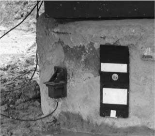
6 Typical response of a Rapid Load Test Load time Converting RAPID (STATNAMIC) to STATIC.. Corrected Static Equivalent curve Dynamic effects Load F Disp Load Rate effects F max Peak Force Point (P pp, pp ) Rapid Load (statnamic) Corrected Equivalent Static Disp Unloading Point (P up, up ) (Correction for Damping and rate effect) Displacement u Unloading point Unloading Point Method (UPM) Developed by Peter Middendorp and Patrick Bermingham in 1989 Used for calculating the static bearing capacity of piles from rapid load tests Assumptions: Long duration of the load in relation to the pile length Rigid Pile No wave phenomenon Measurements Rapid Load Testing A : Load cells B : Reflector Plate C : Acceleration sensor D : Pile head E : Loading Plate F : Spring system plate Load Cells -> F(t) (known) Acc.Sensor -> a(t) (known) Laser/Optical reflector plate > u(t) (known) 23 24
![Unloading Point Method (UPM) F(t) F(t) = Applied force on the pile top Equilibrium: F(t) = F SOIL (t) + F inertia (t) F(t) = Measured load on the pile head [N] F SOIL (t) =](/docs-images/75/72267079/images/7-0.jpg "Force from the soil on the pile [N] F inertia (t) = Internal force [N] F inertia (t) F SOIL (t) = Reaction force of the soil on the pile. Shaft and toe.")
![a(t) = Measured acceleration [m/s 2 ] m = Mass of the pile [kg] F inertia (t) = m a(t) F SOIL (t) F inertia (t) = Reaction force of the mass of the pile.](/docs-images/75/72267079/images/7-1.jpg "Therefore: F SOIL (t) = F(t) - m a(t) 25 26 F SOIL = F static-spring + F V F static-spring = Force dependent on displacement (Plastic spring) Static Resistance F V = Force")
-m x a(t wmax ) w Example: F(t) = 2.8 MN m = 3619 kg a = -30 m/s 2 F static spring = 2.8-3619*-30/1e6 F static spring = 2.8 + 0,11 = 2.")
7 Unloading Point Method (UPM) F(t) F(t) = Applied force on the pile top Equilibrium: F(t) = F SOIL (t) + F inertia (t) F(t) = Measured load on the pile head [N] F SOIL (t) = Force from the soil on the pile [N] F inertia (t) = Internal force [N] F inertia (t) F SOIL (t) = Reaction force of the soil on the pile. Shaft and toe. a(t) = Measured acceleration [m/s 2 ] m = Mass of the pile [kg] F inertia (t) = m a(t) F SOIL (t) F inertia (t) = Reaction force of the mass of the pile. Therefore: F SOIL (t) = F(t) - m a(t) F SOIL = F static-spring + F V F static-spring = Force dependent on displacement (Plastic spring) Static Resistance F V = Force dependent on velocity (Linear damper) = C x v F V F SOIL : F statder k F static = F RLT M x a C x v F F k c F V c U v F static-spring = F(t) - m x a(t) C x v(t) At t = t wmax then v = 0 F static spring = F(t wmax )-m x a(t wmax ) w Example: F(t) = 2.8 MN m = 3619 kg a = -30 m/s 2 F static spring = *-30/1e6 F static spring = ,11 = 2.91MN F V=0 Unloading point F(t) w=max v=0 a

 Uses all data points of the measured signals Analysis is performed numerically F STR is corrected with the inertia force F A Then the force is")
8 C mean Determining C Multiple Cyclic Testing Sheffield Method (SHM) Unloading Point Method is less aureate in pure clay soils Rate effects are large in clay soils Therefore the Sheffield Method is developed. Overview of applicability of available interpretation methods. Method Property Clay Silt Sand Rock UPM Bearing capacity Initial stiffness SHM Bearing capacity Initial stiffness Very suitable, + Suitable, + Questionable, Not really suitable, Not suitable Sheffield Method (SHM) Uses all data points of the measured signals Analysis is performed numerically F STR is corrected with the inertia force F A Then the force is corrected for rate effects with α, β α, β depend on type of clay and pile velocity Preferred practice : α, β determined from Lab. Tests But practical factors are available For calculating the static load displacement also a loading rate v static and a reference velocity v ref is used. 32
 L = Pile lengthe (m) c = stress wave velocity pile material (m/s).")
9 RLT Test Criteria Inertia force < 20% of F(t) (in Singapore, most of time <5%) L Pile Load Depth DLT RLT T f L/c Requirements for RLT Time Time 10 < T f / (L/c p ) < 1000 T f = Duration of the load [s] L = Length of the pile [m] C p = wave velocity in the pile [m/s] T f = Load duration(s) L = Pile lengthe (m) c = stress wave velocity pile material (m/s). 33 Loading duration requirement in ASTM D7838 Video showing the modelling of Dynamic vs Rapid load test From Mr. Martijn van Delft, Allnamics Internation Ltd 36


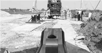
10 Comparison of Load Tests 4. Practices Case Study of RLT -- A. Examples of projects using RAPID LOAD TEST -- where and why it was used effectively? Tons Test at Jn P. Ramlee & Mont Kiara, Kuala Lumpur 500 Tons Tests at Jurong Port & Penang Port 39 40


11 Test in Progress Kuala Lumpur 1400 Tons Test at Jalan Cheras Upgrading Video Tons Test at Quay West, Melbourne 600 Tons Test in Kobe, Japan 43 44


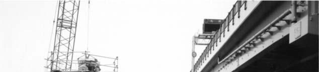
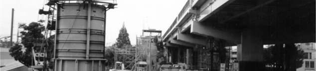
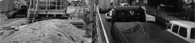
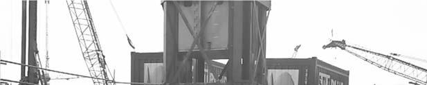
12 3000 Tons Test at Second Link, Johor Singapore Practices - STATNAMIC Tuas West Extension : LTA C1687 & C1688 Barrette piles of up to 4,750 tonnes Singapore Practices - STATNAMIC Singapore Practices - STATRAPID Tuas West Extension : C1687 & C1688 Barrette piles of up to 4,750 tonnes 47 HDB Yishun and Bukit Merah 48


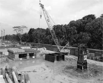
13 Other StatRapid Photos - STATRAPID 4. Practices Case Study of RLT -- B. Case Study of projects using RAPID LOAD TEST -- real number!! Case Study 1 Calibration of Statnamics Test via Static load test at Punggol East Contract 40 Static & Statnamic Load Test 16 th Aug


 1.0 WL 3.")

14 Static Load Test UTP 5 UTP 5-1 st & 2 nd Cycle Load Transfer Curve Pile ref. : UTP 5 Pile Diameter : ɸ 900 mm Pile Length : m Ref. Borehole : BH-9 Pile installed : 2 nd Dec 2011 Test commenced : 17 th Dec 2011 Test completed : 24 th Dec 2011 Working Load : tons 1 st Cycle 2 nd Cycle *T1 & T2 Telltales UTP 5 Load vs Settlement Curve (Dial Gauge) 1.0 WL 3.0 WL Statnamic Test UTP 3 Pile ref. : UTP 3 Pile Diameter : ɸ 900 mm Pile Length : m Ref. Borehole : ABH 9 Test completed : 12 th Mar 2012 Working Load : tons Permanent settlement = 4.1 mm 16 mm 55 56


 477.0 492.")
")
 1,446.0 (2.")
 871.0 (2.")


 (3.")


15 UTP 3 Statnamic Load Transfer Curve UTP 3 - Statnamic Pile Top & Toe Displacement vs Time Plot UTP 3 Statnamic Load vs Settlement Plot Static & Statnamic Test Results Comparison 19 mm 1.0 WL 3.0 WL 59 Pile ref. No. UTP 3 UTP 5 UTP 6 UTP 7 Load Test method Statnamic Static Statnamic Static Pile Diameter ɸ 900 mm ɸ 900 mm ɸ 700 mm ɸ 700 mm Pile Length m m m m Ref. Borehole ABH 9 BH 9 ABH 16 ABH 20 Design WL (tons) Max. load applied (tons) 1,506.0 (3.15 x WL) 1,446.0 (2.94 x WL) (3.35 x WL) (2.95 x WL) Max. static Load 1,498.0 Same as above Same as above (tons) tested (3.14 x WL) (3.29 x WL) Max. Displacement at mm mm mm mm 3.0 x WL Max. Displacement at 1.0 x WL ~4.5 mm ~ ~3 mm ~3 mm Permanent Settlement mm 3.74 mm 4.50 mm 2.74 mm 3.20 mm 60


16 Contribution from Mr Foo H K of RESOURCE PILING PTE LTD Compare Statnamic Pile Load Test Result Against Kentledge Load Test Result Punggol C40 UTP-3&6: Statnamic UTP-1,2,4,5,7&8: Kentledge UTP PILE SIZE TEST DATE SETTLEMENT (mm) DATE CAST (mm) FROM TO 1xWL 2xWL 3xWL NEAREST BOREHOLE REFERENCE Compare UTP-2 vs. UTP-3 Compare UTP-6 vs. UTP /12/2011 4/1/ /1/ ABH /12/ /12/ /12/ BH /3/ /3/ /3/ ABH09 Stn /12/ /12/2011 3/1/ BH /12/ /12/ /12/ BH /3/ /3/ /3/ ABH /11/2011 9/12/ /12/ ABH /12/2011 7/1/ /1/ BH16 Stn


17 UTP-2 UTP-7 UTP-6 UTP-3 UTP UTP UTP-7 UTP UTP


18 Summary Statnamic test works very well as compared with static load test in this site! 70 Case Study 2 Calibration of StatRapid Test via Static load test at Punggol waterway C36 and At Geylang C16 Project Project 1 Geylang HDB project C18 Total no of pile on this site = 714 May-June Additional StstRapid Test done on this 72


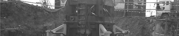
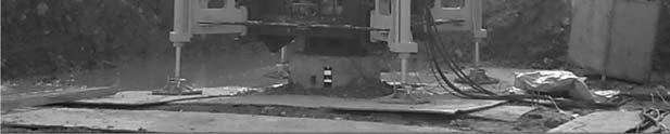
19 StatRapid Setup at test Site Video of StatRapid Test in Singapore 75 76


20 77 78 Near BH3 and BH6 N


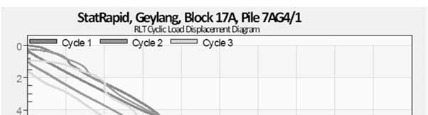
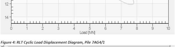
21 Additional StstRapid Test done on this Comparing with Static Load Test Results WL = 9.2 WL = 11.2 mm WL = 11.0 WL = 12.3 mm WL = 7.0 WL = 8.6 mm Settlement using Scale Rule StatRapid Results P=3.7 MN, d=4.5 mm P=7.4 MN, d=9.0 mm 83 84


22 Settlement Rate Issue Correlation of Statnamic vs Static test Recent Malaysia Case 9.6 mm 10.0 mm Pile and Testing Details Testing conducted on 18 July 2014 Pile ID Pile Dia. (m) Pile Length (m) Working Load (kn) Test Load (kn) Test Method Date TP ,000 22,500 Statnamic 18 th July 2014 TP ,900 32,250 Static (Kentledge) 2 nd to 6 th July

 and")
23 N-Values of Boreholes near to test piles Summary Result for TP 1 and TP2 Pile Cut-off level Load Settlement Respond Specific Settlement at Specific Load 2. Normalised Load Settlement Respond of Static Test Pile (TP 1) and Statnamic Test Pile (TP 2) 91 92
24 In summary, the overall load-settlement respond of static equivalent from statnamic compares very well with the conventional static load test results. 3. Load Transfer Curves TP 1 TP 2 Note that the two piles TP1 and TP2 do not have the same length, not the same diameter, and not exactly the same soil profile, yet their normalised load-settlement performance are very rational and very close to one another Comparison of Load Transfer Curves from Static and Statnamic Non-dimensional Comparison of Load Transfer Curves from Static and Statnamic with Normalized Depth Debonded 95 96

25 4. Mobilised Shaft Friction for TP 1 (Statnamic test ) Mobilised Shaft Friction for TP 2 (Static test ) Mobilized End Bearing for TP1 and TP 2 1. The load-settlement behavior of the test piles subjected to Static test and Statnamics test was very similar. 2. Correlation between the two was found to be excellent in terms of (a) specific settlement values at specific load, as well as (b) non-dimensional load settlement respond, where settlement is normalized by pile diameter, and load is normalized by working load. 3. d. The load-transfer curves of the two test piles are very much the same in nature and again, correlation between the two test methods (Statnamic and static) were excellent The mobilized unit shaft friction and unit end bearing mobilized were found to be very consistent between results of static test and Statnamic test. 100
26 5. Correlation -- In conclusion, Statnamic Test was well correlated with the Static Test conducted at this particular site. Summary of correlation tests conducted between Rapid Load tests and Static load tests in Singapore/Malaysia soils A. Test sequence Four (4) possible arrangements of Correlation Tests Same Pile : StatRapid load test -> Static load test Same Pile : Static load test -> StatRapid load test Different nearby piles (with same diameter) with similar soil profile Different nearby piles (with different diameters) with similar soil profile. B. Soil Profiles Typical..Kallang, OA Kallang, Jurong Formation Residual Soils, Jurong Formation 103 HDB Punggol C36 Pile 7C47/1 (STATIC -> STATRAPID) Simplified Soil Profile 15m of loose silty sand 3m of firm clay (Kallang Formation) 3m of dense silty sand 3m of stiff sandy organic clay (Kallang Formation) 27m of dense to very dense silty sand (OA) 104
 74/5 Simplified Soil Profile 12m")
 22.")
 Very good correlation for piles")

27 HDB Punggol C36 Pile 7C47/1 (STATIC -> STATRAPID) HDB Punggol C36 Pile G74/5 (STATRAPID -> STATIC) 74/5 Simplified Soil Profile 12m of soft to firm sandy silt (Kallang Formation) 12m of sandy clay (Kallang Formation) 22.2m of medium to very dense silty sand (OA) HDB Punggol C36 Pile G74/5 (STATRAPID -> STATIC) Very good correlation for piles socketed in OA even with thick layer of loose silt on top! Noted that there was very little permanent settlement in both piles during virgin load cycles by StatRapid or Static Test
 3m of")
 16.")


 111 112")
28 95 Marine Parade (STATRAPID -> STATIC (2 weeks later) 95 Marine Parade (STATRAPID -> STATIC (2 weeks later) Simplified Soil Profile 3m of sandy silt (fill) 3m of silty sand 9m of marine clay (Kallang Formation) 24m of sandy clay (Kallang Formation) 16.5m of sandy silt (OA) Very good correlation for the pile socketed in OA even with thick layer of marine clay Bukit Merah Care is required for correlation as permanent settlement from virgin load by quasi-static test need to be accounted for. This is also true vice versa Simplified Soil Profile 4m of sandy clay Residual soil - fill) 16.18m of hard silt (Jurong Formation)


 Working Load WL (MN) 900 4.")
 - 2 nd - 10.41 mm (1.")
 Soil Profile 6m of sandy silt 6m of hard sandy silt 11.")

 - 2 nd - 9.80 mm (1.")
29 Bukit Merah Very good correlation for the pile socketed in Jurong Formation after accounting for permanent settlement. Care is required for correlation as permanent settlement from virgin load by static test need to be accounted for. This is also true vice versa Yishun N5C6 Yishun N5C6 4 StatRapid vs 4 Static test on different nearby piles Pile - Testing Method P9 G41-1 Static P10 G14-2 StatRapid Pile Dia., D (mm) Working Load WL (MN) Cycle Load (Settlement/pile diameter, %) 1.0 x WL 2.0 x WL 1 st 5.04 mm (0.56%) - 2 nd mm (1.16%) 1 st 3.90 mm (0.39%) - 2 nd mm (0.96%) Soil Profile 6m of sandy silt 6m of hard sandy silt 11.3m of silty sand 4.91m of silty sand StatRapid % - Static % -0.17% -0.20% P11 G50-6 Static P12 G3-2 StatRapid st 4.36 mm (0.55%) - 2 nd mm (1.06%) 1 st 3.80 mm (0.42%) - 2 nd mm (1.09%) 12m firm sandy silt 3m of very stiff sandy silt 15.07m of dense silty sand 6m of sandy silt 6m of sandy clay 15.03m of silty sand 115 StatRapid % - Static % -0.13% 0.03% 116
 and StatRapid (STR) are Rapid Load Tests (RLT) and generate similar pile testing results.")


30 Yishun N5C6 4 StatRapid vs 4 Static test on different neighbouring piles STR vs ST CONCLUSIONS Rapid Load Test (RLT) is a world wide accepted pile testing method, which is covered by many national and international codes, regulations and guidelines. STR Smaller Statnamic (STN) and StatRapid (STR) are Rapid Load Tests (RLT) and generate similar pile testing results. STR Larger STR Larger STR Larger RLT in combination with the UPM analysis method, yields consistent and user independent pile load test results comparable with static load tests. Creep phenomena however are not considered. With the development of StatRapid (STR) a safe, productive and easy to use device has become available, which allows to perform several pile test per day economically and reliably. 118 CONCLUSION ON CORELLECTION WITH STATIC TEST - Excellent correlation were obtained between Rapid Load test vs static test for various type of correlation sequence, and at typical Singapore soils (KF, OA, FJ). - Care need to taken for same pile correlation test conducted for virgin load-settlement cycle vs Unloaded-reloaded cycles. - Rate effect is negligible for Singapore / Malaysia piling practices as most of the piles design are well socketed into stiff soil/weathered rock. NO pile embedded in stiff clay (floating friction pile). - Productivity increase. 119 PRODUCTIVITY IMPROVEMENT CASE STUDY OF STATRAPID C36 Activity Kentledge Load Test Method Construction of kentledge base 1. Kentledge base 1 day - Mob / Setup 1. Test beam and leg setting up 2. Concrete block setting up 3. Equipment setting up 4. Testing Duration Demob / Removal 1. Test beam and leg removal 2. Concrete block removal 3. Equipment removal Trailer Trips 1 set / 0.5 day 360 Ton / day NA 4 days 1 set / 0.5 day 360 Ton / day NA ~40 tonnes per trailer, ~Hundreds of trips each way StatRapid Load Test Method NA NA 1.5 day 1 day NA NA 1 day Four trailer trips each way ESTIMATED DURATION FOR 2,000 ton ~16 days 3.5 days PRODUCTIVITY INCREASE OF ~400%! 120
 Conventional Load Test (Est.")
 Thank You!")
31 Punggol East Contract 36 & Common Green Original Piling Contract Duration: 6.5 months (March Mid-October) Conventional Load Test (Est. Duration) 14 Nos of SLT 7 Nos of SLT were replaced with STATRAPID (Selection of SLTs on the critical path) Thank You!! PROJECT COMPLETION DATE: All SLTs completed by end August Project completed 1.5 months ahead of schedule!! Productivity gain!! 121
Comparisons of rapid load test, dynamic load test and static load test on driven piles
 Comparisons of rapid load test, dynamic load test and static load test on driven piles Bamrungwong, C., Chaisukhang, J. & Janmonta, K. Department of Rural Roads, Thailand Kitiyodom, P. Geotechnical & Foundation
Lesson 25. Static Pile Load Testing, O-cell, and Statnamic. Reference Manual Chapter 18
 Lesson 25 Static Pile Load Testing, O-cell, and Statnamic Reference Manual Chapter 18 STATIC LOAD TESTING Most accurate method to determine static pile capacity Perform at design or construction stage
RAPID PLATE LOAD TESTS ON BEARING STRATUM OF A BUILDING FOUNDATION
 152 RAPID PLATE LOAD TESTS ON BEARING STRATUM OF A BUILDING FOUNDATION H. NEMOTO and H. SAKIHAMA ANDO Corporation, 1-19-61 Ooi-chuo, Fujimino City, Saitama, Japan fvgv182@mb.infoweb.ne.jp Y. NAKASHIMA
PILE LOAD TEST IN OLD ALLUVIUM
 An evening talk organized by GeoSS PILE LOAD TEST IN OLD ALLUVIUM Wong Kai Sin 25 August 2016 1 PILE LOAD TEST IN OLD ALLUVIUM 1.Should we accept or reject the test results? 2.What are the expected unit
Comparison of Static and Dynamic Pile Load Tests at Thi Vai International Port in Viet Nam
 Comparison of Static and Dynamic Pile Load Tests at Thi Vai International Port in Viet Nam Le Phan Ta, Ph.D student, Graduate School of Kanazawa University, Japan (HCMC University of Architecture, Viet
This document downloaded from vulcanhammer.net vulcanhammer.info Chet Aero Marine
 This document downloaded from vulcanhammer.net vulcanhammer.info Chet Aero Marine Don t forget to visit our companion site http://www.vulcanhammer.org Use subject to the terms and conditions of the respective
APPLICATION OF GLOBAL STRAIN EXTENSOMETER (GLOSTREXT) METHOD FOR INSTRUMENTED BORED PILES IN MALAYSIA
 METHOD FOR INSTRUMENTED BORED PILES IN MALAYSIA") Paper published in 1 th International Conference on Piling and Deep Foundations, 31 st May 2 nd June, Amsterdam. APPLICATION OF GLOBAL STRAIN EXTENSOMETER (GLOSTREXT) METHOD FOR INSTRUMENTED BORED PILES
Paper published in 1 th International Conference on Piling and Deep Foundations, 31 st May 2 nd June, Amsterdam. APPLICATION OF GLOBAL STRAIN EXTENSOMETER (GLOSTREXT) METHOD FOR INSTRUMENTED BORED PILES
INTI COLLEGE MALAYSIA
 EGC373 (F) / Page 1 of 5 INTI COLLEGE MALAYSIA UK DEGREE TRANSFER PROGRAMME INTI ADELAIDE TRANSFER PROGRAMME EGC 373: FOUNDATION ENGINEERING FINAL EXAMINATION : AUGUST 00 SESSION This paper consists of
Neutral Plane Method for Drag Force of Deep Foundations and the AASHTO LRFD Bridge Design Specifications
 Neutral Plane Method for Drag Force of Deep Foundations and the AASHTO LRFD Bridge Design Specifications Timothy C. Siegel, P.E., G.E., D.GE Dan Brown and Associates, PC, Knoxville, Tennessee USA Rich
Deep Foundations 2. Load Capacity of a Single Pile
 Deep Foundations 2 Load Capacity of a Single Pile All calculations of pile capacity are approximate because it is almost impossible to account for the variability of soil types and the differences in the
OP-023. INTERPRETATION OF INSTRUMENTED TEST PILE RESULT
 INTERPRETATION OF INSTRUMENTED TEST PILE RESULT Page 1 of 9 WORK INSTRUCTIONS FOR ENGINEERS GSJ Compiled by : Checked by KYW : LSS Approved by : OP-23. INTERPRETATION OF INSTRUMENTED TEST PILE RESULT INTERPRETATION
1 MPa = 150 psi 10 kn = 1 ton 25 mm = 1 inch
 INTELLIGENT COMPACTION: AN OVERVIEW Developed by Jean-Louis Briaud Department of Civil Engineering Texas A&M University Presented to the 5 th Idaho Asphalt Conference, October 27, 5 By Fouad Bayomy Department
Axially Loaded Piles
 Axially Loaded Piles 1 t- Curve Method using Finite Element Analysis The stress-strain relationship for an axially loaded pile can be described through three loading mechanisms: axial deformation in the
Literature review Quasi-static and Dynamic pile load tests
 Literature review Quasi-static and Dynamic pile load tests --------N.Q.HUY-------- Table of contents: I. Introduction.3 II. Quasi static pile load test methods...4 2.1. Quasi static pile load test procedures
Interpretation of Pile Integrity Test (PIT) Results
 Results") Annual Transactions of IESL, pp. 78-84, 26 The Institution of Engineers, Sri Lanka Interpretation of Pile Integrity Test (PIT) Results H. S. Thilakasiri Abstract: A defect present in a pile will severely
Annual Transactions of IESL, pp. 78-84, 26 The Institution of Engineers, Sri Lanka Interpretation of Pile Integrity Test (PIT) Results H. S. Thilakasiri Abstract: A defect present in a pile will severely
TC211 Workshop CALIBRATION OF RIGID INCLUSION PARAMETERS BASED ON. Jérôme Racinais. September 15, 2015 PRESSUMETER TEST RESULTS
 Jérôme Racinais September 15, 215 TC211 Workshop CALIBRATION OF RIGID INCLUSION PARAMETERS BASED ON PRESSUMETER TEST RESULTS Table of contents 1. Reminder about pressuremeter tests 2. General behaviour
BACKGROUND AND INTRODUCTION
 WAVE MECHANICS As applied to pile testing 1 BACKGROUND AND INTRODUCTION Wave Mechanics 2 1 HISTORIC TOOLS AND MATERIALS Timber piles Drop Hammers 10 Days for the Romans to build the bridge over the Rhine
SOME GEOTECHNICAL PROPERTIES OF KLANG CLAY
 SOME GEOTECHNICAL PROPERTIES OF KLANG CLAY Y.C. Tan, S.S. Gue, H.B. Ng 3, P.T. Lee 4 ABSTRACT A series of subsurface investigation including in-situ and laboratory tests has been carefully planned and
Analysis of a single pile settlement
 Engineering manual No. 14 Updated: 06/2018 Analysis of a single pile settlement Program: Pile File: Demo_manual_14.gpi The objective of this engineering manual is to explain the application of the GEO
Dynamic Response of EPS Blocks /soil Sandwiched Wall/embankment
 Proc. of Second China-Japan Joint Symposium on Recent Development of Theory and Practice in Geotechnology, Hong Kong, China Dynamic Response of EPS Blocks /soil Sandwiched Wall/embankment J. C. Chai 1
A wavelet based method for estimating the damping
 1 1 2 3 4 5 6 7 8 9 10 11 12 13 14 15 16 17 18 19 A wavelet based method for estimating the damping ratio in Stanamic pile load tests Pei-hsun Tsai a, Zheng-yi Feng* b, Shang-yuh Lin a a Department of
Calibration of Resistance Factors for Drilled Shafts for the 2010 FHWA Design Method
 Calibration of Resistance Factors for Drilled Shafts for the 21 FHWA Design Method Murad Y. Abu-Farsakh, Ph.D., P.E. Qiming Chen, Ph.D., P.E. Md Nafiul Haque, MS Feb 2, 213 213 Louisiana Transportation
Cone Penetration Testing in Geotechnical Practice
 Cone Penetration Testing in Geotechnical Practice Table Of Contents: LIST OF CONTENTS v (4) PREFACE ix (2) ACKNOWLEDGEMENTS xi (1) SYMBOL LIST xii (4) CONVERSION FACTORS xvi (6) GLOSSARY xxii 1. INTRODUCTION
Numerical Modeling of Interface Between Soil and Pile to Account for Loss of Contact during Seismic Excitation
 Numerical Modeling of Interface Between Soil and Pile to Account for Loss of Contact during Seismic Excitation P. Sushma Ph D Scholar, Earthquake Engineering Research Center, IIIT Hyderabad, Gachbowli,
Drilled Shaft Foundations in Limestone. Dan Brown, P.E., Ph.D. Dan Brown and Associates
 Drilled Shaft Foundations in Limestone Dan Brown, P.E., Ph.D. Dan Brown and Associates Foundation Engineering How we teach our students Fundamental understanding of soil and rock behavior (good!) Focus
Maximum Envelope of Lateral Resistance through Dynamic Increasing Energy Test in Piles
 Maximum Envelope of Lateral Resistance through Dynamic Increasing Energy Test in Piles R.M. Valverde, F. Massad Abstract. The traditional dynamic load test, based on the one-dimensional wave propagation
THE STRUCTURAL DESIGN OF PILE FOUNDATIONS BASED ON LRFD FOR JAPANESE HIGHWAYS
 THE STRUCTURAL DESIGN OF PILE FOUNDATIONS BASED ON LRFD FOR JAPANESE HIGHWAYS Hideaki Nishida 1,Toshiaki Nanazawa 2, Masahiro Shirato 3, Tetsuya Kohno 4, and Mitsuaki Kitaura 5 Abstract One of the motivations
COEFFICIENT OF DYNAMIC HORIZONTAL SUBGRADE REACTION OF PILE FOUNDATIONS ON PROBLEMATIC GROUND IN HOKKAIDO Hirofumi Fukushima 1
 COEFFICIENT OF DYNAMIC HORIZONTAL SUBGRADE REACTION OF PILE FOUNDATIONS ON PROBLEMATIC GROUND IN HOKKAIDO Hirofumi Fukushima 1 Abstract In this study, static loading tests and dynamic shaking tests of
INTRODUCTION TO STATIC ANALYSIS PDPI 2013
 INTRODUCTION TO STATIC ANALYSIS PDPI 2013 What is Pile Capacity? When we load a pile until IT Fails what is IT Strength Considerations Two Failure Modes 1. Pile structural failure controlled by allowable
Static Pile Head Impedance using 3D Nonlinear FEM Analysis
 Static Pile Head Impedance using 3D Nonlinear FEM Analysis Ichiro NAGASHIMA Technology Center, Taisei Corporation, 344-1 Nasecho, Totsuka-ku, Yokohama 245-51, Japan, ichiro.nagashima@sakura.taisei.co.jp
Engineeringmanuals. Part2
 Engineeringmanuals Part2 Engineering manuals for GEO5 programs Part 2 Chapter 1-12, refer to Engineering Manual Part 1 Chapter 13. Pile Foundations Introduction... 2 Chapter 14. Analysis of vertical load-bearing
NUMERICAL STUDY ON LATERAL SPREADING OF LIQUEFIED GROUND BEHIND A SHEET PILE MODEL IN A LARGE SCALE SHAKE TABLE TEST
 13 th World Conference on Earthquake Engineering Vancouver, B.C., Canada August 1-6, 24 Paper No. 2515 NUMERICAL STUDY ON LATERAL SPREADING OF LIQUEFIED GROUND BEHIND A SHEET PILE MODEL IN A LARGE SCALE
Back-Calculation of Winkler Foundation Parameters for Dynamic Analysis of Piles from Field Test Data
 Back-Calculation of Winkler Foundation Parameters for Dynamic Analysis of Piles from Field Test Data ABSTRACT A. (Rajah) Anandarajah, Jigang Zhang and G. Gnanaranjan Department of Civil Engineering Johns
Effective stress analysis of pile foundations in liquefiable soil
 Effective stress analysis of pile foundations in liquefiable soil H. J. Bowen, M. Cubrinovski University of Canterbury, Christchurch, New Zealand. M. E. Jacka Tonkin and Taylor Ltd., Christchurch, New
INCREASE IN PILE CAPACITY WITH TIME IN MISSOURI RIVER ALLUVIUM
 INCREASE IN PILE CAPACITY WITH TIME IN MISSOURI RIVER ALLUVIUM Paul J. Axtell Jacob W. Owen Scott D. Vollink U.S. Army Corps of Engineers U.S. Army Corps of Engineers U.S. Army Corps of Engineers Kansas
CPT Guide 5 th Edition. CPT Applications - Deep Foundations. Gregg Drilling & Testing, Inc. Dr. Peter K. Robertson Webinar # /2/2013
 Gregg Drilling & Testing, Inc. Site Investigation Experts CPT Applications - Deep Foundations Dr. Peter K. Robertson Webinar #6 2013 CPT Guide 5 th Edition Robertson & Cabal (Robertson) 5 th Edition 2012
Numerical Modelling of Dynamic Earth Force Transmission to Underground Structures
 Numerical Modelling of Dynamic Earth Force Transmission to Underground Structures N. Kodama Waseda Institute for Advanced Study, Waseda University, Japan K. Komiya Chiba Institute of Technology, Japan
Discussion: behaviour of jacked and driven piles in sandy soil
 Title Discussion: behaviour of jacked and driven piles in sandy soil Author(s) Yang, J; Tham, LG; Lee, PKK; Chan, ST; Yu, F Citation Géotechnique, 27, v. 7 n., p. 47-478 Issued Date 27 URL http://hdl.handle.net/1722/7161
Results from long-term measurement in piles of drag force and downdrag
 Results from long-term measurement in piles of drag force and downdrag The Bäckebol site in June 1968 Fellenius, B.H., 26. Results from long-term measurement in piles of drag force and downdrag. Canadian
Design Procedures For Dynamically Loaded Foundations
 Design Procedures For Dynamically Loaded Foundations 1/11 Choice of parameters for equivalent lumped systems Lumped mass : the mass of the foundation and supported machinery Damping : 1 Geometrical(or
Prof. Dr.-Ing. Martin Achmus Institute of Soil Mechanics, Foundation Engineering and Waterpower Engineering. Monopile design
 Prof. Dr.-Ing. Martin Achmus Institute of Soil Mechanics, Foundation Engineering and Waterpower Engineering Monopile design Addis Ababa, September 2010 Monopile design Presentation structure: Design proofs
Centrifuge Shaking Table Tests and FEM Analyses of RC Pile Foundation and Underground Structure
 Centrifuge Shaking Table s and FEM Analyses of RC Pile Foundation and Underground Structure Kenji Yonezawa Obayashi Corporation, Tokyo, Japan. Takuya Anabuki Obayashi Corporation, Tokyo, Japan. Shunichi
PDA Workshop: Stresses, Integrity, Energy and Capacity
 PDA Workshop: Stresses, Integrity, Energy and Capacity Ir Richard C L Yu IEM 2 Sep 2013 Dynamic Pile Monitoring For each blow determine Pile driving stresses Pile integrity Hammer performance Capacity
Improving site specific modified driving formulae using high frequency displacement monitoring
 Proc. 20 th NZGS Geotechnical Symposium. Eds. GJ Alexander & CY Chin, Napier Improving site specific modified driving formulae using high frequency displacement monitoring R Damen Brian Perry Civil, Auckland,
ON THE PREDICTION OF EXPERIMENTAL RESULTS FROM TWO PILE TESTS UNDER FORCED VIBRATIONS
 Transactions, SMiRT-24 ON THE PREDICTION OF EXPERIMENTAL RESULTS FROM TWO PILE TESTS UNDER FORCED VIBRATIONS 1 Principal Engineer, MTR & Associates, USA INTRODUCTION Mansour Tabatabaie 1 Dynamic response
Shakedown analysis of pile foundation with limited plastic deformation. *Majid Movahedi Rad 1)
") Shakedown analysis of pile foundation with limited plastic deformation *Majid Movahedi Rad 1) 1) Department of Structural and Geotechnical Engineering, Széchenyi István University Egyetem Tér1, H-9026
Shakedown analysis of pile foundation with limited plastic deformation *Majid Movahedi Rad 1) 1) Department of Structural and Geotechnical Engineering, Széchenyi István University Egyetem Tér1, H-9026
S E C T I O N 1 2 P R O D U C T S E L E C T I O N G U I D E - H E L I C A L S C R E W P I L E F O U N D A T I O N S
 1. P R O D U C T S E L E C T I O N G U I D E - H E L I C A L S C R E W P I L E F O U N D A T I O N S Helical foundation pile includes a lead and extension(s). The lead section is made of a central steel
EFFECT OF SOIL TYPE LOCATION ON THE LATERALLY LOADED SINGLE PILE
 International Journal of Civil Engineering and Technology (IJCIET) Volume 9, Issue 12, December 2018, pp. 1196 1205, Article ID: IJCIET_09_12 122 Available online at http://www.ia aeme.com/ijciet/issues.asp?jtype=ijciet&vtype=
NUMERICAL ANALYSIS OF DAMAGE OF RIVER EMBANKMENT ON SOFT SOIL DEPOSIT DUE TO EARTHQUAKES WITH LONG DURATION TIME
 Proceedings of the International Symposium on Engineering Lessons Learned from the 2011 Great East Japan Earthquake, March 1-4, 2012, Tokyo, Japan NUMERICAL ANALYSIS OF DAMAGE OF RIVER EMBANKMENT ON SOFT
IN SITU TESTING TECHNOLOGY FOR FOUNDATION & EARTHQUAKE ENGINEERING. Wesley Spang, Ph.D., P.E. AGRA Earth & Environmental, Inc.
 IN SITU TESTING TECHNOLOGY FOR FOUNDATION & EARTHQUAKE ENGINEERING Wesley Spang, Ph.D., P.E. AGRA Earth & Environmental, Inc. Portland, Oregon In situ testing of soil, which essentially consists of evaluating
NEW DOWN-HOLE PENETROMETER (DHP-CIGMAT) FOR CONSTRUCTION APPLICATIONS
 FOR CONSTRUCTION APPLICATIONS") NEW DOWN-HOLE PENETROMETER (DHP-CIGMAT) FOR CONSTRUCTION APPLICATIONS 1 2 C. Vipulanandan 1, Ph.D., M. ASCE and Omer F. Usluogullari 2 Chairman, Professor, Director of Center for Innovative Grouting Materials
NEW DOWN-HOLE PENETROMETER (DHP-CIGMAT) FOR CONSTRUCTION APPLICATIONS 1 2 C. Vipulanandan 1, Ph.D., M. ASCE and Omer F. Usluogullari 2 Chairman, Professor, Director of Center for Innovative Grouting Materials
Finite Element Investigation of the Interaction between a Pile and a Soft Soil focussing on Negative Skin Friction
 NGM 2016 Reykjavik Proceedings of the 17 th Nordic Geotechnical Meeting Challenges in Nordic Geotechnic 25 th 28 th of May Finite Element Investigation of the Interaction between a Pile and a Soft Soil
EVALUATION OF BENDING LOAD IN BATTER PILES SET IN SOFT CLAY
 EVALUATION OF BENDING LOAD IN BATTER PILES SET IN SOFT CLAY Tetsuya KOHNO 1, Hiroyuki TANAKA 2, Masahiro SHIRATO 3 and Shoichi NAKATANI 4 Abstract In this study, we conducted centrifuge tests to evaluate
EQUIVALENT FRACTURE ENERGY CONCEPT FOR DYNAMIC RESPONSE ANALYSIS OF PROTOTYPE RC GIRDERS
 EQUIVALENT FRACTURE ENERGY CONCEPT FOR DYNAMIC RESPONSE ANALYSIS OF PROTOTYPE RC GIRDERS Abdul Qadir Bhatti 1, Norimitsu Kishi 2 and Khaliq U Rehman Shad 3 1 Assistant Professor, Dept. of Structural Engineering,
GEOTECHNICAL CRITERION FOR SERVICEABILITY LIMIT STATE OF HORIZONTALLY-LOADED DEEP FOUNDATIONS
 Abstract GEOTECHNICAL CITEION FO SEVICEABILITY LIMIT STATE OF HOIZONTALLY-LOADED DEEP FOUNDATIONS Masahiro Shirato 1, Shoichi Nakatani 2, Kenji Matsui 3, and Takashi Nakaura 4 This paper presents a first
EXAMPLE OF PILED FOUNDATIONS
 EXAMPLE OF PILED FOUNDATIONS The example developed below is intended to illustrate the various steps involved in the determination of the seismic forces developed in piles during earthquake shaking. The
Seabed instability and 3D FE jack-up soil-structure interaction analysis
 Seabed instability and 3D FE jack-up soil-structure interaction analysis Lindita Kellezi, GEO Danish Geotechnical Institute, Denmark Gregers Kudsk, Maersk Contractors, Denmark Hugo Hofstede, Marine Structure
Bored piles in clay and Codes of Practice. Malcolm Bolton
 Bored piles in clay and Codes of Practice Malcolm Bolton Background: design and decision-making Why is design not yet evidence-based? Reliance on past practice, rather than validation. Safety factors have
Geotechnical issues in seismic assessments: When do I need a geotechnical specialist?
 Geotechnical issues in seismic assessments: When do I need a geotechnical specialist? B.H. Rama & S.J. Palmer Tonkin & Taylor Ltd (T+T), Wellington, New Zealand. 2016 NZSEE Conference ABSTRACT: The Canterbury
Seismic Response Analysis of Structure Supported by Piles Subjected to Very Large Earthquake Based on 3D-FEM
 Seismic Response Analysis of Structure Supported by Piles Subjected to Very Large Earthquake Based on 3D-FEM *Hisatoshi Kashiwa 1) and Yuji Miyamoto 2) 1), 2) Dept. of Architectural Engineering Division
NON-LINEAR VISCOELASTIC MODEL OF STRUCTURAL POUNDING
 3 th World Conference on Earthquake Engineering Vancouver, B.C., Canada August -6, 004 Paper No. 308 NON-LINEAR VISCOELASTIC MODEL OF STRUCTURAL POUNDING Robert JANKOWSKI SUMMARY Pounding between structures
PILE FOUNDATION RESPONSE DUE TO SOIL LATERAL SPREADING DURING HYOGO-KEN NANBU EARTHQUAKE
 PILE FOUNDATION RESPONSE DUE TO SOIL LATERAL SPREADING DURING HYOGO-KEN NANBU EARTHQUAKE Kohji KOYAMADA, Yuji MIYAMOTO and Yuji SAKO Kobori Research Complex, Kajima Corporation, Tokyo, Japan Email: koyamada@krc.kajima.co.jp
EFFECTIVE STRESS ANALYSES OF TWO SITES WITH DIFFERENT EXTENT OF LIQUEFACTION DURING EAST JAPAN EARTHQUAKE
 Proceedings of the International Symposium on Engineering Lessons Learned from the 211 Great East Japan Earthquake, March 1-4, 212, Tokyo, Japan EFFECTIVE STRESS ANALYSES OF TWO SITES WITH DIFFERENT EXTENT
Landslide FE Stability Analysis
 Landslide FE Stability Analysis L. Kellezi Dept. of Geotechnical Engineering, GEO-Danish Geotechnical Institute, Denmark S. Allkja Altea & Geostudio 2000, Albania P. B. Hansen Dept. of Geotechnical Engineering,
Dynamic Analysis to Study Soil-Pile Interaction Effects
 by Pallavi Ravishankar, Neelima Satyam in Indexed in Scopus Compendex and Geobase Elsevier, Chemical Abstract Services-USA, Geo-Ref Information Services- USA, List B of Scientific Journals, Poland, Directory
ASD and LRFD Methods Codes and Economics of Dynamic Testing ASTM D4945
 ASD and LRFD Methods Codes and Economics of Dynamic Testing ASTM D4945 Load Testing. Static Load Testing ASTM D1143 Deadload Testing React. Piles/Anchors Static Load Tests are the standard Costly: Need
Gapping effects on the lateral stiffness of piles in cohesive soil
 Gapping effects on the lateral stiffness of piles in cohesive soil Satyawan Pranjoto Engineering Geology, Auckland, New Zealand. M. J. Pender Department of Civil and Environmental Engineering, University
Certification of a High Capacity Force Machine for Testing of Load Cells According to OIML R60
 Certification of a High Capacity Force Machine for Testing of Load Cells According to OIML R60 Bernd Meißner Physikalisch-Technische Bundesanstalt Weighing Instruments Laboratory Braunschweig Abstract
EVALUATION OF SITE CHARACTERISTICS IN LIQUEFIABLE SOILS
 4 th International Conference on Earthquake Geotechnical Engineering June 25-28, 27 Paper No. 1651 EVALUATION OF SITE CHARACTERISTICS IN LIQUEFIABLE SOILS Konstantinos TREVLOPOULOS 1, Nikolaos KLIMIS 2
DYNAMIC ANALYSIS OF PILES IN SAND BASED ON SOIL-PILE INTERACTION
 October 1-17,, Beijing, China DYNAMIC ANALYSIS OF PILES IN SAND BASED ON SOIL-PILE INTERACTION Mohammad M. Ahmadi 1 and Mahdi Ehsani 1 Assistant Professor, Dept. of Civil Engineering, Geotechnical Group,
Additional Pile Design Considerations
 Additional Pile Design Considerations PDCA 2015 Professor Driven Pile Institute Patrick Hannigan GRL Engineers, Inc. What Are Additional Pile Design Considerations? Time Dependent Soil Strength Changes
Implementation of Laterally Loaded Piles in Multi-Layer Soils
 Implementation of Laterally Loaded Piles in Multi-Layer Soils JTRP SPR- 3261 Final SAC meeting SAC members Mir Zaheer and Keith Hoernschemeyer Purdue University Introduction Analysis developed for the
ANALYSES OF SOIL-STRUCTURE INTERACTION BASED ON VERTICAL LOAD TESTS OF DISPLACEMENT PILES
 Technical Sciences 18(4), 2015, 261 270 ANALYSES OF SOIL-STRUCTURE INTERACTION BASED ON VERTICAL LOAD TESTS OF DISPLACEMENT PILES Department of Geotechnical engineering Vilnius Gediminas Technical University
SETTLEMENT EVALUATION OF SHALLOW FOUNDATION SUBJECTED TO VERTICAL LOAD ON THE MULTI-LAYER SOIL
 International Journal of Civil Engineering and Technology (IJCIET) Volume 9, Issue 12, December 18, pp. 1025 1034, Article ID: IJCIET_09_12_105 Available online at http://www.iaeme.com/ijciet/issues.asp?jtype=ijciet&vtype=9&itype=12
Cavity Expansion Methods in Geomechanics
 Cavity Expansion Methods in Geomechanics by Hai-Sui Yu School of Civil Engineering, University of Nottingham, U. K. KLUWER ACADEMIC PUBLISHERS DORDRECHT / BOSTON / LONDON TABLE OF CONTENTS Foreword Preface
Numerical Investigation of the Effect of Recent Load History on the Behaviour of Steel Piles under Horizontal Loading
 Numerical Investigation of the Effect of Recent Load History on the Behaviour of Steel Piles under Horizontal Loading K. Abdel-Rahman Dr.-Ing., Institute of Soil Mechanics, Foundation Engineering and Waterpower
CAPWAP rules Important!
 CAPWAP rules Important! Unit friction < 4 ksf (200 kpa ) for most soils QT (+TG) < Dmax, toe to assure activation QS < 0.2 inch (5 mm ) usually 0.1 inch; 2.5 mm SS, ST < 0.4 s/ft (1.3 s/m ) if higher,
Supplementary Problems for Chapter 7
 Supplementary Problems for Chapter 7 Problem 7.1 consolidation test has been carried out on a standard 19 mm thick clay sample. The oedometer s deflection gauge indicated 1.66 mm, just before the removal
Chapter (12) Instructor : Dr. Jehad Hamad
 Instructor : Dr. Jehad Hamad") Chapter (12) Instructor : Dr. Jehad Hamad 2017-2016 Chapter Outlines Shear strength in soils Direct shear test Unconfined Compression Test Tri-axial Test Shear Strength The strength of a material is the
Chapter (12) Instructor : Dr. Jehad Hamad 2017-2016 Chapter Outlines Shear strength in soils Direct shear test Unconfined Compression Test Tri-axial Test Shear Strength The strength of a material is the
IMPACT RESPONSE ANALYSIS OF LARGE SCALE RC GIRDER WITH SAND CUSHION
 -Technical Paper- IMPACT RESPONSE ANALYSIS OF LARGE SCALE RC GIRDER WITH SAND CUSHION Abdul Qadir BHATTI *1, Norimitsu KISHI *2, Shin-ya OKADA *3 and Hisashi KONNO *4 ABSTRACT In order to establish a proper
TRANSPORTATION RESEARCH BOARD. Static and Seismic Design of Piles for Downdrag. Thursday, October 4, :00-3:30 PM ET
 TRANSPORTATION RESEARCH BOARD Static and Seismic Design of Piles for Downdrag Thursday, October 4, 2018 2:00-3:30 PM ET The Transportation Research Board has met the standards and requirements of the Registered
Chapter (11) Pile Foundations
 Pile Foundations") Chapter (11) Introduction Piles are structural members that are made of steel, concrete, or timber. They are used to build pile foundations (classified as deep foundations) which cost more than shallow
Chapter (11) Introduction Piles are structural members that are made of steel, concrete, or timber. They are used to build pile foundations (classified as deep foundations) which cost more than shallow
Model tests and FE-modelling of dynamic soil-structure interaction
 Shock and Vibration 19 (2012) 1061 1069 1061 DOI 10.3233/SAV-2012-0712 IOS Press Model tests and FE-modelling of dynamic soil-structure interaction N. Kodama a, * and K. Komiya b a Waseda Institute for
Evaluation of dynamic behavior of culverts and embankments through centrifuge model tests and a numerical analysis
 Computer Methods and Recent Advances in Geomechanics Oka, Murakami, Uzuoka & Kimoto (Eds.) 2015 Taylor & Francis Group, London, ISBN 978-1-138-00148-0 Evaluation of dynamic behavior of culverts and embankments
APPENDIX J. Dynamic Response Analysis
 APPENDIX J Dynamic Response Analysis August 25, 216 Appendix J Dynamic Response Analysis TABLE OF CONTENTS J1 INTRODUCTION... 1 J2 EARTHQUAKE TIME HISTORIES... 1 J3 MODEL AND INPUT DATA FOR SITE RESPONSE
DRILLED DISPLACMENT PILE PERFORMANCE IN COASTAL PLAIN AND RESIDUAL SOILS
 DRILLED DISPLACMENT PILE PERFORMANCE IN COASTAL PLAIN AND RESIDUAL SOILS Presented by: W. Morgan NeSmith, P.E. Berkel & Company Contractors Inc. 770.941.5100 mnesmith@berkelapg.com SC Engineering Conference
World Academy of Science, Engineering and Technology International Journal of Geotechnical and Geological Engineering Vol:11, No:9, S.
 Design and Construction Validation of Pile Performance through High Strain Pile Dynamic Tests for both Contiguous Flight Auger and Drilled Displacement Piles S. Pirrello Abstract Sydney s booming real
CONTENTS. 1. GeneralsG Field Investigation WorkG Laboratory Testing Work Surface Soil Description-- 7.
 CONTENTS Page 1. GeneralsG 4 2. Field Investigation WorkG 4 3. Laboratory Testing Work--- 5 4. Surface Soil Description-- 7 Appendix A Borehole Location Plan 11 Soil Profile-- 15 Bore Logs--=---- 18 Appendix
Chapter 12 Subsurface Exploration
 Page 12 1 Chapter 12 Subsurface Exploration 1. The process of identifying the layers of deposits that underlie a proposed structure and their physical characteristics is generally referred to as (a) subsurface
Safety Concepts and Calibration of Partial Factors in European and North American Codes of Practice
 Safety Concepts and Calibration of Partial Factors in European and North American Codes of Practice The Dutch approach on Geotechnical Design by Eurocode 7 Adriaan van Seters Hein Jansen Fugro GeoServices
Chapter 7: Settlement of Shallow Foundations
 Chapter 7: Settlement of Shallow Foundations Introduction The settlement of a shallow foundation can be divided into two major categories: (a) elastic, or immediate settlement and (b) consolidation settlement.
A STUDY ON DAMAGE TO STEEL PIPE PILE FOUNDATION ON RECLAIMED LAND DURING HYOGO-KEN-NANBU EARTHQUAKE
 A STUDY ON DAMAGE TO STEEL PIPE PILE FOUNDATION ON RECLAIMED LAND DURING HYOGO-KEN-NANBU EARTHQUAKE Takaaki IKEDA 1, Shigeru MIWA And Hiroshi OH-OKA 3 SUMMARY Damage investigation was conducted on steel
HKIE-GD Workshop on Foundation Engineering 7 May Shallow Foundations. Dr Limin Zhang Hong Kong University of Science and Technology
 HKIE-GD Workshop on Foundation Engineering 7 May 2011 Shallow Foundations Dr Limin Zhang Hong Kong University of Science and Technology 1 Outline Summary of design requirements Load eccentricity Bearing
Dynamic Tests on Ring Shear Apparatus
 , July 1-3, 2015, London, U.K. Dynamic Tests on Ring Shear Apparatus G. Di Massa Member IAENG, S. Pagano, M. Ramondini Abstract Ring shear apparatus are used to determine the ultimate shear strength of
Congreso Internacional de Fundaciones Profundas de Bolivia Santa Cruz, Bolivia, 12 al 15 de Mayo de 2015 Day 1: Software Demonstrations
 Applications of Stress Wave Theory to Deep Foundations with an Emphasis on The Wave Equation (GRLWEAP) Congreso Internacional de Fundaciones Profundas de Bolivia Santa Cruz, Bolivia, 12 al 15 de Mayo de
Study on Settlement Prediction Model of High-Speed Railway Bridge Pile Foundation
 Journal of Applied Science and Engineering, Vol. 18, No. 2, pp. 187 193 (2015) DOI: 10.6180/jase.2015.18.2.12 Study on Settlement Prediction Model of High-Speed Railway Bridge Pile Foundation Zhong-Bo
Summary and Review of Part II of the Symposium on Pile Foundations
 Summary and Review of Part II of the Symposium on Pile Foundations G. A. LEONARDS, Purdue University PILE FOUNDATIONS share with cellular cofferdams the distinction of yielding most reluctantly to the
Views on Accuracy of Tests and Analyses
 Piling & Deep Foundations Asia 29 Workshop A, July 13, 29 Views on Accuracy of Tests and Analyses Bengt H. Fellenius ======================================================================================================================
FOUNDATION DESIGN AND CASE STUDIES
 The University of the West Indies Organization of American States PROFESSIONAL DEVELOPMENT PROGRAMME: COASTAL INFRASTRUCTURE DESIGN, CONSTRUCTION AND MAINTENANCE A COURSE IN DESIGN OF MARINE STRUCTURES
Harmonized European standards for construction in Egypt
 Harmonized European standards for construction in Egypt EN 1998 - Design of structures for earthquake resistance Jean-Armand Calgaro Chairman of CEN/TC250 Organised with the support of the Egyptian Organization