Views on Accuracy of Tests and Analyses
|
|
|
- Magdalene Hampton
- 5 years ago
- Views:
Transcription

1 Piling & Deep Foundations Asia 29 Workshop A, July 13, 29 Views on Accuracy of Tests and Analyses Bengt H. Fellenius ====================================================================================================================== 9658 First Street Tel.: (778) Sidney, BC, Canada e-address: V8L 3C6 Web site: [

2 2

3 Don't connect the reference beams to each other. A foot up on one beam and both references are disturbed! 3
4 See? 4

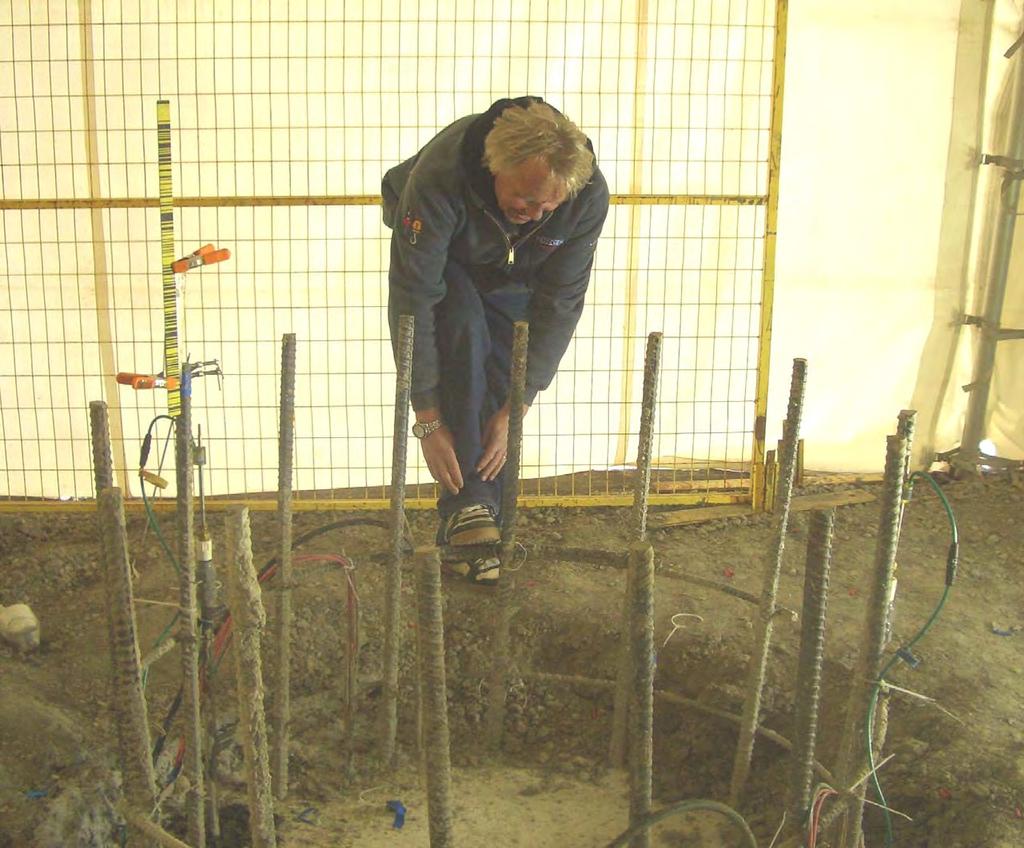
5 Make sure the support stakes of the reference beams are far enough away from the support of the kentledge load and the latter far enough from the pile. The distances are prescribed in the ASTM Guidelines. 5

6 Most piles are installed slightly inclined. Consider this when arranging the reaction structure and always use a swivel plate to avoid edge loading. 6
7 Fellenius
8 The error can be small or it can be large. Results from two tests at the same site using the same equipment testing two adjacent piles, one after the other Head-down O-cell Pile August 26 2, Shinho-Pile August 26 1,5 25 Error in Jack Load (KN) % Error Error (KN) 1, 5 15% Error 5 2.5% Error 2, 4, 6, 8, 1, Loadcell (KN) 5, 1, 15, Loadcell load (KN) Note, the test on the pile called "O-cell pile" is a head-down test after a preceding O-cell test. 8
9 A routine static loading test provides the load-movement of the pile head... and the pile capacity? 9
10 DECOURT 235 1
11 T e l l t a l e s A telltale measures shortening of a pile and must never be arranged to measure movement. Let toe movement be the pile head movement minus the pile shortening. For a single telltale, the shortening divided by the distance between the pile head and the telltale toe is the average strain over that length. For two telltales, the distance to use is that between the telltale tips. The strain times the cross section area of the pile times the pile material E-modulus is the average load in the pile. To plot a load distribution, where should the load value be plotted? Midway of the length or above or below? 11
12 Load distribution for constant unit shaft resistance PILE HEAD Average 1 Load A1 LOAD, Q PILE TOE 5 Midheight h 1 DEPTH, z A2 Load Distribution Q = az r s = a 12
13 Linearly increasing unit shaft resistance and its load distribution Unit Shaft Resistance az Average Load x A1 LOAD, Q A 1 = 3 ax 3 h DEPTH, z h A2 Load Distribution Q = az 2 /2 A2 = a( h 3 2 3x h + 6 A 1 = A2 2x 3 ) X is where the average load should be plotted h X = 58h 3 =. 13
14 Today, telltales are not used for determining strain (load) in a pile because using strain gages is a more assured, more accurate, and cheaper means of instrumentation. However, it is good policy to include a toe-telltale to measure toe movement. If arranged to measure shortening of the pile, it can also be used as an approximate back-up for the average load in the pile. The use of vibratory strain gages (sometimes, electrical resistance gages) is a well-established, accurate, and reliable means for determining loads imposed in the test pile. It is very unwise to cut corners by field-attaching single strain gages to the re-bar cage. Always install factory assembled sister bar gages. 14
 Rebar Strain Meter Rebar")
15 Rebar Strain Meter Sister Bar Three bars?! Instrument Cables Instrument Cable Reinforcing Rebar or Strand Reinforcing Rebar or Strand Wire Tie (2 places) Rebar Strain Meter Rebar Strain Meter (3 places, 12 apart) Wire Tie Tied to Reinforcing Rebar Tied to Reinforcing Rings Hayes 22 15
16 Lunch Generator turned off break Night Night Example of Electromagnetic Interference (EMI) noise from a generator and power cable affecting vibrating wire strain gages Sources of noise are for example arc welding, machinery ignition, power generators, and power cables, etc. Continual noise will impart a general trend of overall accuracy of data by increasing its spread between data points. Sudden noise, for example, when starting up a machine, the ignition may cause a spike in the readings. Electronic noise tends to result in a reduction in strain gage values, whereas magnetic noise increases the strain gage values. Osborne, N. and Tan, G.H., 29. Factors influencing the performance of strain-gage instrumented Monitoring systems. Geotechnical News, (27)
17 We have got the strain. How to we get the load? Load is stress times area Stress is Modulus (E) times strain σ = E ε The modulus is the key 17
18 For a concrete pile or a concrete-filled bored pile, the modulus to use is the combined modulus of concrete, reinforcement, and steel casing E comb = E s A A s s + + E A c c A c E comb = combined modulus E s = modulus for steel A s = area of steel E c = modulus for concrete A c = area of concrete 18
19 The modulus of steel is 2 GPa (27 GPa for those weak at heart) The modulus of concrete is....? Hard to answer. There is a sort of relation to the cylinder strength and the modulus usually appears as a value around 3 GPa, or perhaps 2 GPa or so, perhaps more. This is not good enough answer but being vague is not necessary. The modulus can be determined from the strain measurements. Calculate first the change of strain for a change of load and plot the values against the strain. E t = Δσ Δε Values are known 19
20 Example of Tangent Modulus Plot TANGENT MODULUS (GPa) Level 1 Level 2 Level 3 Level 4 Level 5 Best Fit Line MICROSTRAIN 2
21 In the stress range of the static loading test, modulus of concrete is not constant, but a more or less linear relation to the strain dσ E t = = aε + dε b Which can be integrated to: σ = a 2 ε 2 + bε But stress is also a function of secant modulus and strain: σ = Es ε Combined, we get a useful relation: E =.5a ε + s b and Q = A E s ε 21
22 Example of Tangent Modulus Plot 1 Level 1 9 Level 2 Intercept is b TANGENT MODULUS (GPa) Slope is a Level 3 Level 4 Level 5 Best Fit Line MICROSTRAIN 22
23 Note, just because a strain-gage has registered some strain values during a test does not guarantee that the data are useful. Strains unrelated to force can develop due to variations in the pile material and temperature and amount to as much as about 5± microstrain. Therefore, the test must be designed to achieve strains due to imposed force of ideally about 5 microstrain and beyond. If the imposed strains are smaller, the relative errors and imprecision will be large, and interpretation of the test data becomes uncertain, causing the investment in instrumentation to be less than meaningful. The test should engage the pile material up to at least half the strength. Preferably, aim for reaching close to the strength. Moreover, each gage reading must be assessed as to it being true to the actual strain and free from interference. 23
24 Results of static loading tests on 4 m long, instrumented steel piles in a saprolite soil. LOAD (KN) 2, 4, 6, 8, 1, UNIT SHAFT SHEAR (KPa) DEPTH (m) DEPTH (m) ? Each gage reading provides a load value. The treatment of the values has to be with understanding of the accuracy/error of each. The unit shaft resistance is calculated as the difference in evaluated loads for adjacent gage levels divided with shaft area (= distance between gage levels times pile circumference). The load difference is about the same magnitude as the error in each load value! 24
25 A more thoughtful analysis of the data LOAD (KN) UNIT SHAFT SHEAR (KPa) 2, 4, 6, 8, 1, ß = ß = DEPTH (m) ß =.4 DEPTH (m) ß =
26 Could there be load in the pile before we start the loading test? and, if so, Could such load have any significant effect on the data evaluation?
27 Determining load from strain-gage measurements in the pile The strain-gage measurement is supposed to be the change of strain relative the no-load situation (i.e., when no external load acts at the gage location). But, is the no-load situation really the reading taken at the beginning of the test? What is the true zero-reading to use? 27
28 We often assume somewhat optimistically or naively that the reading before the start of the test represents the no-load condition. However, at the time of the start of the loading test, loads do exist in the pile and they are often large. For a grouted pipe pile or a concrete cylinder pile, these loads are to a part the effect of the temperature generated during the curing of the grout. Then, the re-consolidation (set-up) of the soil after the driving or construction of the pile will impose additional loads on the pile. 28
29 What we measure is the increase of load in the pile due to the load applied to the pile head. The external-origin load in the pile that was there before we started the test is called "Residual Load". 29
30 Normalized Applied Load Load distributions in static loading tests on four instrumented piles in clay D E P T H 3
31 Example from Gregersen et al., 1973 LOAD (KN) LOAD (KN) Residual True minus Residual DEPTH (m) Pile DA Sand DEPTH (m) True Pile BC, Tapered A. Distribution of residual load in DA and BC before start of the loading test B. Load and resistance in DA for the ultimate load applied 31
32 Clay DEPTH (m) LOAD (KN) 5 1, 1,5 2, 2,5 Static Loading Test at Pend Oreille, Sandpoint, Idaho, for the realignment of US95 46 m diameter, 45 m embedment, closed-toe pipe pile driven in soft clay 2+ m Fellenius et al
33 Distribution of Measured Loads ( False Resistance ) and True Resistance 5 LOAD (KN) 5 1, 1,5 2, 2,5 Residual Load From Test data and from Calculations 1 DEPTH (m) True Resistance From Test data and from Calculations 35 4 Fellenius et al Measured Load From Test data and from Calculations 33
34 FHWA tests on.9 m diameter bored piles One in sand and one in clay (Baker et al., 199 and Briaud et al., 2) Cone Stress and SPT N-Index (MPa and bl/.3 m) Cone Stress (MPa) Silty Sand DEPTH (m ) q c Silty Sand N DEPTH (m ) Clay Clay 1 Sand 1 Pile 4 Pile
35 ANALYSIS RESULTS: Load-transfer curves.. LOAD (KN) LOAD (KN) 1, 2, 3, 4, 5, 1, 2, 3, 4, 5,. LOAD (KN) 1, 2, 3, 4, 5, DEPTH (m) Residual Load Measured Distribution Measured Distribution True Distribution 2. Residual Load DEPTH (m) Measured Distribution True Distribution PILE PILE 4 SAND SAND PILE 7 CLAY 35
36 Results of analysis of a Monotube pile in sand (Fellenius et al., 2) LOAD (KN) 1, 2, 3, 5 Residual Load Measured Resistance DEPTH (m) True Resistance 25 36
37 Method for evaluating the residual load distribution 2 RESISTANCE (KN) 5 1, 1,5 2, Measured Load DEPTH (m) Shaft Resistance True Resistance Extrapolated True Resistance 16 Residual Load Measured Shaft Resistance Divided by 2 37
38 The approach can be applied also to dynamic tests CPT Profile A Cone Stress, q t (MPa) B LOAD (KN) 5 1, 1, CAPWAP Determined Resistance Distribution Depth (m) Depth (m) Resistance Distribution (Data from Axelsson 1998) 38
39 Analysis Procedure LOAD (KN) 5 1, 1, Residual Load Measured Load Depth (m) Shaft Resistance Distribution Divided by True Resistance Extension of Matching Fellenius
40 Results LOAD (KN) 5 1, 1,5 2, 2 4 Depth (m) CAPWAP Determined Resistance True Resistance Residual CAPWAP Shaft Divided by 2 True Shaft Resistance 2 Fellenius 22 4
41 Presence of residual load is not just of academic interest 1, 8 No Strain Softening Residual Load present 1, 8 With Strain Softening Residual Load present LOAD (KN) 6 4 No Residual Load LOAD (KN) 6 4 No Residual Load 2 OFFSET LIMIT LOAD OFFSET LIMIT LOAD MOVEMENT (mm) MOVEMENT (mm) 41
42 Toe Resistance A 1,2 1, TOE TELLTALE HEAD LOAD (KN) TOE Does not this shape of measured toe movement suggest that there is a distinct toe capacity? MOVEMENT (mm) 42
43 A 1,2 1, TOE TELLTALE HEAD B 1,2 1, HEAD LOAD (KN) TOE LOAD (KN) TOE MOVEMENT (mm) "Virgin" Toe Curve MOVEMENT (mm) No, it only appears that way when we forget to consider the residual toe load (also called the initial, or virgin toe movement) 43
44 Residual load and other influences on evaluated load distribution
45 STRAIN (µε) 9d Strain measured during the 218-day wait-period between driving (grouting) and testing d 23d 3d 39d Do these strains really represent load in the pile, as present before the start of the static loading test? DEPTH (m) d 59d 82d 99d 5 122d 55 6 At an E- modulus of 3 GPa, this strain change corresponds to a load change of 3,2 KN 218d Day of Test 45
46 Concrete hydration temperature measured in a grouted concrete cylinder pile 7 TEMPERATURE ( C) Temperature at various depths in the grout of a.4 m center hole in a 56 m long,.6 m diameter, cylinder pile HOURS AFTER GROUTING Pusan Case 46
47 7 6 Temperatures measured in a 74.5 m long, 2.6 m diameter bored pile 7 6 Temperatures measured in a 74.5 m long, 2.6 m diameter bored pile TEMPERATURE ( C) TEMPERATURE ( C) Start of Static Loading Test DAY AFTER GROUTING DAY AFTER GROUTING Temperature records during curing of grout in the Golden Ears Bridge test pile, Vancouver, BC. Data courtesy of Trow Engineering Inc. and Amec Inc. 47
48 CHANGE OF STRAIN (µε) Rebar Shortening Change of strain measured in a 74.5 m long, 2.6 m diameter bored pile Slight Recovery of Shortening DAY AFTER GROUTING Change of strain during the hydration of the grout in the Golden Ears Bridge test pile 48
 pieces with")

49 Photo of short (2 m) pieces with plastic tube enabling them to be submerged 49
50 Temperature During Curing of a 2m Lab Specimen TEMPTATURE (ºC) S W N E April 25, Time (h) 5
51 Strain History During Curing of a 2 m Lab Specimen 5 PHC Piece CHANGE OF STRAIN (µε) A INCREASING SHORTENING OF REBAR RECOVERY OF SHORTENING (LENGTHENING) Days after Grouting Pusan Case 51
52 Submerging the short piece, letting it swell from absorption of water 1 Concrete Cylinder Piece 5 STRAIN (µε) INCREASING TENSION Pile piece submerged Time (days) S N E W 52
53 The strain gages themselves ar not are temperature sensitive, but the records may be! The vibrating wire and the rebar have almost the same temperature coefficient. However, the coefficients of steel and concrete are slightly different. This will influence the strains during the cooling of the grout. More important, the rise of temperature in the grout could affect the zero reading of the wire and its strain calibration. It is necessary to heat-cycle (anneal) the gage before calibration. (A routine measure of Geokon, US manufacturer of vibrating wire gages). 53
54 Readings should be taken immediately before (and after) every event of the piling work and not just during the actual loading test The No-Load Readings will tell what happened to the gage before the start of the test and will be helpful in assessing the possibility of a shift in the reading value representing the no-load condition If the importance of the No-Load Readings is recognized, and if those readings are reviewed and evaluated, then, we are ready to consider the actual readings during the test 54
55 Of course, we must consider also other aspects: 55
56 Interpretation of a series of tests performed at different times Change of Horizontal Stress (KPa) Cell D1 5 Days 1 Day 8 Days 4 Months 22 Months Movement (mm) Results thought due to set-up and explained as Increase in Horizontal Effective Stress Movement (mm) Fellenius 22 5 Days 1 Day 8 Days 4 Months 22 Months Results plotted According to Movement Path 56
57 Also the best field work can get messed up if the analysis and conclusion effort loses sight of the history of the data LOAD (KN) 2, 1,5 1, DYNAMIC TEST DYNAMIC TEST in a DYNAMIC series of TEST blows STATIC TEST Repeated STATIC TEST MOVEMENT (mm) The dynamic test (CAPWAP) was performed after the static test. The redriving (ten blows) forced the pile down additionally about 45 mm. 57
58 Often the past routines are nothing but jog trotting along with the humdrum past. For example, incorporating unloading/reloading cycles is useless and actually impairs a test. 58
59 Does unloading/reloading add anything of value to a test? Result on a test on a 2.5 m diameter, 85.5 m long bored pile 3 25 Repeat Acceptance test Criterion Acceptance Criterion LOAD (MN) MOVEMENT (mm) 59
60 Plotting the repeat test in proper sequence 3 25 Acceptance Criterion Repeat test test plotted in sequence in sequence of testing of i LOAD (MN) MOVEMENT (mm) 6
61 2, 1,5 LOAD (KN) 1, MOVEMENT (mm) The above series of unloading/reloading has added nothing but cost the client a lot of money. 61

62 Thank you for your attention
Lesson 25. Static Pile Load Testing, O-cell, and Statnamic. Reference Manual Chapter 18
 Lesson 25 Static Pile Load Testing, O-cell, and Statnamic Reference Manual Chapter 18 STATIC LOAD TESTING Most accurate method to determine static pile capacity Perform at design or construction stage
PILE LOAD TEST IN OLD ALLUVIUM
 An evening talk organized by GeoSS PILE LOAD TEST IN OLD ALLUVIUM Wong Kai Sin 25 August 2016 1 PILE LOAD TEST IN OLD ALLUVIUM 1.Should we accept or reject the test results? 2.What are the expected unit
OP-023. INTERPRETATION OF INSTRUMENTED TEST PILE RESULT
 INTERPRETATION OF INSTRUMENTED TEST PILE RESULT Page 1 of 9 WORK INSTRUCTIONS FOR ENGINEERS GSJ Compiled by : Checked by KYW : LSS Approved by : OP-23. INTERPRETATION OF INSTRUMENTED TEST PILE RESULT INTERPRETATION
Fellenius, B.H., and Tan, S.A., Analysis of bidirectional-cell tests for Icon Condominiums, Singapore. Proceedings of the 9th International
 Fellenius,.H., and Tan, S.A., 1. Analysis of bidirectional-cell tests for Icon Condominiums, Singapore. Proceedings of the 9th International Conference on Testing and esign Methods for eep Foundations,
A presentation of UniPile software for calculation of Capacity, Drag Force, Downdrag, and Settlement for Piles and Piled Foundations
 528 River Road, Ottawa, Ontario, Canada, K1V 1E9 E: info@unisoftgs.com A presentation of UniPile software for calculation of Capacity, Drag Force, Downdrag, and Settlement for Piles and Piled Foundations
Deep Foundations 2. Load Capacity of a Single Pile
 Deep Foundations 2 Load Capacity of a Single Pile All calculations of pile capacity are approximate because it is almost impossible to account for the variability of soil types and the differences in the
INTRODUCTION TO STATIC ANALYSIS PDPI 2013
 INTRODUCTION TO STATIC ANALYSIS PDPI 2013 What is Pile Capacity? When we load a pile until IT Fails what is IT Strength Considerations Two Failure Modes 1. Pile structural failure controlled by allowable
S E C T I O N 1 2 P R O D U C T S E L E C T I O N G U I D E - H E L I C A L S C R E W P I L E F O U N D A T I O N S
 1. P R O D U C T S E L E C T I O N G U I D E - H E L I C A L S C R E W P I L E F O U N D A T I O N S Helical foundation pile includes a lead and extension(s). The lead section is made of a central steel
Implementation of Pile Setup in the LRFD Design of Driven Piles in Louisiana
 Implementation of Pile Setup in the LRFD Design of Driven Piles in Louisiana Md. Nafiul Haque (Ph.D. Candidate) Murad Y. Abu-Farsakh, Ph.D., P.E. March 1, 2016 Louisiana Transportation Conference OUTLINE
EN Eurocode 7. Section 3 Geotechnical Data Section 6 Spread Foundations. Trevor L.L. Orr Trinity College Dublin Ireland.
 EN 1997 1: Sections 3 and 6 Your logo Brussels, 18-20 February 2008 Dissemination of information workshop 1 EN 1997-1 Eurocode 7 Section 3 Geotechnical Data Section 6 Spread Foundations Trevor L.L. Orr
MEASUREMENT AND PREDICTION OF THE LOAD DISTRIBUTION AND PERFORMANCE OF CONTINUOUS FLIGHT AUGER PILES
 MEASUREMENT AND PREDICTION OF THE LOAD DISTRIBUTION AND PERFORMANCE OF CONTINUOUS FLIGHT AUGER PILES by Thomas Leon Pine BEng, BComm This Thesis is presented for the Degree of Master of Engineering Science
[5] Stress and Strain
![[5] Stress and Strain](/thumbs/95/123344550.jpg "[5] Stress and Strain") [5] Stress and Strain Page 1 of 34 [5] Stress and Strain [5.1] Internal Stress of Solids [5.2] Design of Simple Connections (will not be covered in class) [5.3] Deformation and Strain [5.4] Hooke s Law
[5] Stress and Strain Page 1 of 34 [5] Stress and Strain [5.1] Internal Stress of Solids [5.2] Design of Simple Connections (will not be covered in class) [5.3] Deformation and Strain [5.4] Hooke s Law
CPT Guide 5 th Edition. CPT Applications - Deep Foundations. Gregg Drilling & Testing, Inc. Dr. Peter K. Robertson Webinar # /2/2013
 Gregg Drilling & Testing, Inc. Site Investigation Experts CPT Applications - Deep Foundations Dr. Peter K. Robertson Webinar #6 2013 CPT Guide 5 th Edition Robertson & Cabal (Robertson) 5 th Edition 2012
Axially Loaded Piles
 Axially Loaded Piles 1 t- Curve Method using Finite Element Analysis The stress-strain relationship for an axially loaded pile can be described through three loading mechanisms: axial deformation in the
PDA Workshop: Stresses, Integrity, Energy and Capacity
 PDA Workshop: Stresses, Integrity, Energy and Capacity Ir Richard C L Yu IEM 2 Sep 2013 Dynamic Pile Monitoring For each blow determine Pile driving stresses Pile integrity Hammer performance Capacity
CHAPTER 3 THE EFFECTS OF FORCES ON MATERIALS
 CHAPTER THE EFFECTS OF FORCES ON MATERIALS EXERCISE 1, Page 50 1. A rectangular bar having a cross-sectional area of 80 mm has a tensile force of 0 kn applied to it. Determine the stress in the bar. Stress
CHAPTER 8 ANALYSES OF THE LATERAL LOAD TESTS AT THE ROUTE 351 BRIDGE
 CHAPTER ANALYSES OF THE LATERAL LOAD TESTS AT THE ROUTE 351 BRIDGE.1 INTRODUCTION An important objective of this research is to determine whether accurate analyses of the lateral load-deflection behavior
There are three main types of structure - mass, framed and shells.
 STRUCTURES There are three main types of structure - mass, framed and shells. Mass structures perform due to their own weight. An example would be a dam. Frame structures resist loads due to the arrangement
Pseudo-Elastic Response and Performance of Micropiles copes
 Pseudo-Elastic Response and Performance of Micropiles copes ISM Workshop 2009 London, U.K. May 12, 2009 Terence P. Holman, Ph.D., P.E. CONSTRUCTION & GEOTECHNICAL SERVICES NEW JERSEY FLORIDA NEW YORK MASSACHUSETTS
THE STRUCTURAL DESIGN OF PILE FOUNDATIONS BASED ON LRFD FOR JAPANESE HIGHWAYS
 THE STRUCTURAL DESIGN OF PILE FOUNDATIONS BASED ON LRFD FOR JAPANESE HIGHWAYS Hideaki Nishida 1,Toshiaki Nanazawa 2, Masahiro Shirato 3, Tetsuya Kohno 4, and Mitsuaki Kitaura 5 Abstract One of the motivations
Measurement of effective stress shear strength of rock
 Measurement of effective stress shear strength of rock R. A. Failmezger, P.E., F. ASCE In-Situ Soil Testing, L.C., Lancaster, Virginia USA D. J. White, Ph. D., P.E. Iowa State University, Ames, Iowa USA
Discussion: behaviour of jacked and driven piles in sandy soil
 Title Discussion: behaviour of jacked and driven piles in sandy soil Author(s) Yang, J; Tham, LG; Lee, PKK; Chan, ST; Yu, F Citation Géotechnique, 27, v. 7 n., p. 47-478 Issued Date 27 URL http://hdl.handle.net/1722/7161
Results from long-term measurement in piles of drag force and downdrag
 Results from long-term measurement in piles of drag force and downdrag The Bäckebol site in June 1968 Fellenius, B.H., 26. Results from long-term measurement in piles of drag force and downdrag. Canadian
Boreholes. Implementation. Boring. Boreholes may be excavated by one of these methods: 1. Auger Boring 2. Wash Boring 3.
 Implementation Boreholes 1. Auger Boring 2. Wash Boring 3. Rotary Drilling Boring Boreholes may be excavated by one of these methods: 4. Percussion Drilling The right choice of method depends on: Ground
Mechanics of Solids. Mechanics Of Solids. Suraj kr. Ray Department of Civil Engineering
 Mechanics Of Solids Suraj kr. Ray (surajjj2445@gmail.com) Department of Civil Engineering 1 Mechanics of Solids is a branch of applied mechanics that deals with the behaviour of solid bodies subjected
This document downloaded from vulcanhammer.net vulcanhammer.info Chet Aero Marine
 This document downloaded from vulcanhammer.net vulcanhammer.info Chet Aero Marine Don t forget to visit our companion site http://www.vulcanhammer.org Use subject to the terms and conditions of the respective
Liquefaction Induced Negative Skin Friction from Blast-induced Liquefaction Tests with Auger-cast Piles
 6 th International Conference on Earthquake Geotechnical Engineering 1-4 November 2015 Christchurch, New Zealand Liquefaction Induced Negative Skin Friction from Blast-induced Liquefaction Tests with Auger-cast
NORMAL STRESS. The simplest form of stress is normal stress/direct stress, which is the stress perpendicular to the surface on which it acts.
 NORMAL STRESS The simplest form of stress is normal stress/direct stress, which is the stress perpendicular to the surface on which it acts. σ = force/area = P/A where σ = the normal stress P = the centric
DESIGNING FOR DOWNDRAG ON UNCOATED AND BITUMEN COATED PILES
 DESIGNING FOR DOWNDRAG ON UNCOATED AND BITUMEN COATED PILES Jean-Louis BRIAUD, PhD, PE President of ISSMGE Professor and Holder of the Buchanan Chair Texas A&M University Piling and Deep Foundations Middle
Interpretation of Pile Integrity Test (PIT) Results
 Results") Annual Transactions of IESL, pp. 78-84, 26 The Institution of Engineers, Sri Lanka Interpretation of Pile Integrity Test (PIT) Results H. S. Thilakasiri Abstract: A defect present in a pile will severely
Annual Transactions of IESL, pp. 78-84, 26 The Institution of Engineers, Sri Lanka Interpretation of Pile Integrity Test (PIT) Results H. S. Thilakasiri Abstract: A defect present in a pile will severely
STRAIN GAUGES YEDITEPE UNIVERSITY DEPARTMENT OF MECHANICAL ENGINEERING
 STRAIN GAUGES YEDITEPE UNIVERSITY DEPARTMENT OF MECHANICAL ENGINEERING 1 YEDITEPE UNIVERSITY ENGINEERING FACULTY MECHANICAL ENGINEERING LABORATORY 1. Objective: Strain Gauges Know how the change in resistance
AN ABSTRACT OF THE THESIS OF
 AN ABSTRACT OF THE THESIS OF Nasim Adami for the degree of Master of Science in Civil Engineering presented on October 28, 213. Title: Development of an ACIP Pile-Specific Load-Displacement Model. Abstract
Engineeringmanuals. Part2
 Engineeringmanuals Part2 Engineering manuals for GEO5 programs Part 2 Chapter 1-12, refer to Engineering Manual Part 1 Chapter 13. Pile Foundations Introduction... 2 Chapter 14. Analysis of vertical load-bearing
APPLICATION OF GLOBAL STRAIN EXTENSOMETER (GLOSTREXT) METHOD FOR INSTRUMENTED BORED PILES IN MALAYSIA
 METHOD FOR INSTRUMENTED BORED PILES IN MALAYSIA") Paper published in 1 th International Conference on Piling and Deep Foundations, 31 st May 2 nd June, Amsterdam. APPLICATION OF GLOBAL STRAIN EXTENSOMETER (GLOSTREXT) METHOD FOR INSTRUMENTED BORED PILES
Paper published in 1 th International Conference on Piling and Deep Foundations, 31 st May 2 nd June, Amsterdam. APPLICATION OF GLOBAL STRAIN EXTENSOMETER (GLOSTREXT) METHOD FOR INSTRUMENTED BORED PILES
Assessment of Calculation Procedures for Piles in Clay based on Static Loading Tests Anders Hust Augustesen
 Assessment of Calculation Procedures for Piles in Clay based on Static Loading Tests By Anders Hust Augustesen 1 Agenda Presentation of calculation procedures Basis for the evaluation of the calculation
PDDC 1 st Semester Civil Engineering Department Assignments of Mechanics of Solids [ ] Introduction, Fundamentals of Statics
![PDDC 1 st Semester Civil Engineering Department Assignments of Mechanics of Solids [ ] Introduction, Fundamentals of Statics](/thumbs/92/109382806.jpg "PDDC 1 st Semester Civil Engineering Department Assignments of Mechanics of Solids [ ] Introduction, Fundamentals of Statics") Page1 PDDC 1 st Semester Civil Engineering Department Assignments of Mechanics of Solids [2910601] Introduction, Fundamentals of Statics 1. Differentiate between Scalar and Vector quantity. Write S.I.
Page1 PDDC 1 st Semester Civil Engineering Department Assignments of Mechanics of Solids [2910601] Introduction, Fundamentals of Statics 1. Differentiate between Scalar and Vector quantity. Write S.I.
Use of Ultra-High Performance Concrete in Geotechnical and Substructure Applications
 Use of Ultra-High Performance Concrete in Geotechnical and Substructure Applications i PI: Muhannad Suleiman Co-PI: Sri Sritharan Graduate Research Assistant: Thomas L. Vande Voort January 13, 29 IOWA
EDEXCEL NATIONAL CERTIFICATE/DIPLOMA MECHANICAL PRINCIPLES AND APPLICATIONS NQF LEVEL 3 OUTCOME 1 - LOADING SYSTEMS TUTORIAL 3 LOADED COMPONENTS
 EDEXCEL NATIONAL CERTIICATE/DIPLOMA MECHANICAL PRINCIPLES AND APPLICATIONS NQ LEVEL 3 OUTCOME 1 - LOADING SYSTEMS TUTORIAL 3 LOADED COMPONENTS 1. Be able to determine the effects of loading in static engineering
Liquefaction and Foundations
 Liquefaction and Foundations Amit Prashant Indian Institute of Technology Gandhinagar Short Course on Seismic Design of Reinforced Concrete Buildings 26 30 November, 2012 What is Liquefaction? Liquefaction
(Refer Slide Time: 02:18)
") Geology and Soil Mechanics Prof. P. Ghosh Department of Civil Engineering Indian Institute of Technology Kanpur Lecture 40 Shear Strength of Soil - C Keywords: Shear strength of soil, direct shear test,
Geology and Soil Mechanics Prof. P. Ghosh Department of Civil Engineering Indian Institute of Technology Kanpur Lecture 40 Shear Strength of Soil - C Keywords: Shear strength of soil, direct shear test,
The University of Melbourne Engineering Mechanics
 The University of Melbourne 436-291 Engineering Mechanics Tutorial Four Poisson s Ratio and Axial Loading Part A (Introductory) 1. (Problem 9-22 from Hibbeler - Statics and Mechanics of Materials) A short
Chapter. Materials. 1.1 Notations Used in This Chapter
 Chapter 1 Materials 1.1 Notations Used in This Chapter A Area of concrete cross-section C s Constant depending on the type of curing C t Creep coefficient (C t = ε sp /ε i ) C u Ultimate creep coefficient
Chapter (11) Pile Foundations
 Pile Foundations") Chapter (11) Introduction Piles are structural members that are made of steel, concrete, or timber. They are used to build pile foundations (classified as deep foundations) which cost more than shallow
Chapter (11) Introduction Piles are structural members that are made of steel, concrete, or timber. They are used to build pile foundations (classified as deep foundations) which cost more than shallow
Bending Load & Calibration Module
 Bending Load & Calibration Module Objectives After completing this module, students shall be able to: 1) Conduct laboratory work to validate beam bending stress equations. 2) Develop an understanding of
SHEET PILE WALLS. Mehdi Mokhberi Islamic Azad University
 SHEET PILE WALLS Mehdi Mokhberi Islamic Azad University Lateral Support In geotechnical engineering, it is often necessary to prevent lateral soil movements. Tie rod Anchor Sheet pile Cantilever retaining
Finite Element Investigation of the Interaction between a Pile and a Soft Soil focussing on Negative Skin Friction
 NGM 2016 Reykjavik Proceedings of the 17 th Nordic Geotechnical Meeting Challenges in Nordic Geotechnic 25 th 28 th of May Finite Element Investigation of the Interaction between a Pile and a Soft Soil
High Tech High Top Hat Technicians. An Introduction to Solid Mechanics. Is that supposed to bend there?
 High Tech High Top Hat Technicians An Introduction to Solid Mechanics Or Is that supposed to bend there? Why don't we fall through the floor? The power of any Spring is in the same proportion with the
EDEXCEL NATIONAL CERTIFICATE/DIPLOMA SCIENCE FOR TECHNICIANS OUTCOME 1 - STATIC AND DYNAMIC FORCES TUTORIAL 3 STRESS AND STRAIN
 EDEXCEL NATIONAL CERTIFICATE/DIPLOMA SCIENCE FOR TECHNICIANS OUTCOME 1 - STATIC AND DYNAMIC FORCES TUTORIAL 3 STRESS AND STRAIN 1 Static and dynamic forces Forces: definitions of: matter, mass, weight,
Maximum Envelope of Lateral Resistance through Dynamic Increasing Energy Test in Piles
 Maximum Envelope of Lateral Resistance through Dynamic Increasing Energy Test in Piles R.M. Valverde, F. Massad Abstract. The traditional dynamic load test, based on the one-dimensional wave propagation
ME 243. Mechanics of Solids
 ME 243 Mechanics of Solids Lecture 2: Stress and Strain Ahmad Shahedi Shakil Lecturer, Dept. of Mechanical Engg, BUET E-mail: sshakil@me.buet.ac.bd, shakil6791@gmail.com Website: teacher.buet.ac.bd/sshakil
IN SITU TESTING TECHNOLOGY FOR FOUNDATION & EARTHQUAKE ENGINEERING. Wesley Spang, Ph.D., P.E. AGRA Earth & Environmental, Inc.
 IN SITU TESTING TECHNOLOGY FOR FOUNDATION & EARTHQUAKE ENGINEERING Wesley Spang, Ph.D., P.E. AGRA Earth & Environmental, Inc. Portland, Oregon In situ testing of soil, which essentially consists of evaluating
Safety Concepts and Calibration of Partial Factors in European and North American Codes of Practice
 Safety Concepts and Calibration of Partial Factors in European and North American Codes of Practice The Dutch approach on Geotechnical Design by Eurocode 7 Adriaan van Seters Hein Jansen Fugro GeoServices
HKIE-GD Workshop on Foundation Engineering 7 May Shallow Foundations. Dr Limin Zhang Hong Kong University of Science and Technology
 HKIE-GD Workshop on Foundation Engineering 7 May 2011 Shallow Foundations Dr Limin Zhang Hong Kong University of Science and Technology 1 Outline Summary of design requirements Load eccentricity Bearing
1 MPa = 150 psi 10 kn = 1 ton 25 mm = 1 inch
 INTELLIGENT COMPACTION: AN OVERVIEW Developed by Jean-Louis Briaud Department of Civil Engineering Texas A&M University Presented to the 5 th Idaho Asphalt Conference, October 27, 5 By Fouad Bayomy Department
Strength of Materials (15CV 32)
") Strength of Materials (15CV 32) Module 1 : Simple Stresses and Strains Dr. H. Ananthan, Professor, VVIET,MYSURU 8/21/2017 Introduction, Definition and concept and of stress and strain. Hooke s law, Stress-Strain
Strength of Materials (15CV 32) Module 1 : Simple Stresses and Strains Dr. H. Ananthan, Professor, VVIET,MYSURU 8/21/2017 Introduction, Definition and concept and of stress and strain. Hooke s law, Stress-Strain
IDE 110 Mechanics of Materials Spring 2006 Final Examination FOR GRADING ONLY
 Spring 2006 Final Examination STUDENT S NAME (please print) STUDENT S SIGNATURE STUDENT NUMBER IDE 110 CLASS SECTION INSTRUCTOR S NAME Do not turn this page until instructed to start. Write your name on
1. A pure shear deformation is shown. The volume is unchanged. What is the strain tensor.
 Elasticity Homework Problems 2014 Section 1. The Strain Tensor. 1. A pure shear deformation is shown. The volume is unchanged. What is the strain tensor. 2. Given a steel bar compressed with a deformation
Investigation of basic elements loading and tension of heavy hydraulic presses for metallurgical production
 Investigation of basic elements loading and tension of heavy hydraulic presses for metallurgical production Ganush V. I. National metallurgical academe of Ukraine Ostroverhov N. P., Sultan A. V., Dzichkovky
PES Institute of Technology
 PES Institute of Technology Bangalore south campus, Bangalore-5460100 Department of Mechanical Engineering Faculty name : Madhu M Date: 29/06/2012 SEM : 3 rd A SEC Subject : MECHANICS OF MATERIALS Subject
MECHANICS OF MATERIALS. Prepared by Engr. John Paul Timola
 MECHANICS OF MATERIALS Prepared by Engr. John Paul Timola Mechanics of materials branch of mechanics that studies the internal effects of stress and strain in a solid body. stress is associated with the
Purpose of this Guide: To thoroughly prepare students for the exact types of problems that will be on Exam 3.
 ES230 STRENGTH OF MTERILS Exam 3 Study Guide Exam 3: Wednesday, March 8 th in-class Updated 3/3/17 Purpose of this Guide: To thoroughly prepare students for the exact types of problems that will be on
GROUND IMPROVEMENT WORKSHOP JUNE 2010 PERTH, AUSTRALIA. CHAIRMAN OF T.C. Ground Improvement
 GROUND IMPROVEMENT WORKSHOP 11-12 JUNE 2010 PERTH, AUSTRALIA GROUND IMPROVEMENT IN EXTREME GROUND CONDITIONS Presented by Serge VARAKSIN CHAIRMAN OF T.C. Ground Improvement EPEC Bang Bo: Works Procedure
BACKGROUND AND INTRODUCTION
 WAVE MECHANICS As applied to pile testing 1 BACKGROUND AND INTRODUCTION Wave Mechanics 2 1 HISTORIC TOOLS AND MATERIALS Timber piles Drop Hammers 10 Days for the Romans to build the bridge over the Rhine
Strength of Material. Shear Strain. Dr. Attaullah Shah
 Strength of Material Shear Strain Dr. Attaullah Shah Shear Strain TRIAXIAL DEFORMATION Poisson's Ratio Relationship Between E, G, and ν BIAXIAL DEFORMATION Bulk Modulus of Elasticity or Modulus of Volume
APPLICATION OF INTENSIVE SHEAR REINFORCEMENT TO SPLICING SLEEVE JOINT OF PRE-FABRICATED REINFORCEMENT ASSEMBLY
 13 th World Conference on Earthquake Engineering Vancouver, B.C., Canada August 1-6, 24 Paper No. 587 APPLICATION OF INTENSIVE SHEAR REINFORCEMENT TO SPLICING SLEEVE JOINT OF PRE-FABRICATED REINFORCEMENT
LRFD GEOTECHNICAL IMPLEMENTATION
 LRFD GEOTECHNICAL IMPLEMENTATION Ching-Nien Tsai, P.E. LADOTD Pavement and Geotechnical Services In Conjunction with LTRC WHY LRFD FHWA deadline - October 2007 LRFD is a better method Risk is quantified
Chapter (5) Allowable Bearing Capacity and Settlement
 Allowable Bearing Capacity and Settlement") Chapter (5) Allowable Bearing Capacity and Settlement Introduction As we discussed previously in Chapter 3, foundations should be designed for both shear failure and allowable settlement. So the allowable
Chapter (5) Allowable Bearing Capacity and Settlement Introduction As we discussed previously in Chapter 3, foundations should be designed for both shear failure and allowable settlement. So the allowable
Use of CPT for design, monitoring, and performance verification of compaction projects
 Cone Stress, q t (MPa) 2 3 Sleeve Friction (KPa) 2 4 Pore Pressure (KPa) 2 7, Friction Ratio (%) 2 3 4 Profile Mixed Y 2 2 2 2 CLAY 3 3 3 3 4 4 4 4 SAN D Use of CPT for design, monitoring, and performance
Type approval granted by the Finnish Ministry of the Environment
 RR Piling Manual 2 Type approval granted by the Finnish Ministry of the Environment 2..02. RR Piling Manual 1. General This manual deals with impact-driven RR piles. It is an abridgement of the RR Piling
CIVIL DEPARTMENT MECHANICS OF STRUCTURES- ASSIGNMENT NO 1. Brach: CE YEAR:
 MECHANICS OF STRUCTURES- ASSIGNMENT NO 1 SEMESTER: V 1) Find the least moment of Inertia about the centroidal axes X-X and Y-Y of an unequal angle section 125 mm 75 mm 10 mm as shown in figure 2) Determine
Installation Manual. Models 4911A/4911. VW Rebar Strain Meters
 Installation Manual Models 4911A/4911 VW Rebar Strain Meters No part of this instruction manual may be reproduced, by any means, without the written consent of Geokon, Inc. The information contained herein
T15 STRAND. Geotechnical applications WIRE STRAND
 Geotechnical applications T15 STRAND WIRE STRAND All anchorage systems produced by TTM: post-tensioning, slabs and geotechnical applications (rock anchorages) are tested with the three types of wire strands
Dynamic behavior of turbine foundation considering full interaction among facility, structure and soil
 Dynamic behavior of turbine foundation considering full interaction among facility, structure and soil Fang Ming Scholl of Civil Engineering, Harbin Institute of Technology, China Wang Tao Institute of
Tension, Compression, and Shear
 01Ch01.qxd 2/10/09 7:32 PM Page 1 1 ension, Compression, and Shear Normal Stress and Strain Problem 1.2-1 A hollow circular post ABC (see figure) supports a load P 1 7.5 kn acting at the top. A second
National Exams May 2015
 National Exams May 2015 04-BS-6: Mechanics of Materials 3 hours duration Notes: If doubt exists as to the interpretation of any question, the candidate is urged to submit with the answer paper a clear
Cone Penetration Testing in Geotechnical Practice
 Cone Penetration Testing in Geotechnical Practice Table Of Contents: LIST OF CONTENTS v (4) PREFACE ix (2) ACKNOWLEDGEMENTS xi (1) SYMBOL LIST xii (4) CONVERSION FACTORS xvi (6) GLOSSARY xxii 1. INTRODUCTION
Mechanical Response of a Composite Steel, Concrete- Filled Pile
 Mechanical Response of a Composite Steel, Concrete- Filled Pile Joseph Labuz, Principal Investigator Department of Civil, Environmental, and Geo- Engineering University of Minnesota June 2018 Research
Solid Mechanics Homework Answers
 Name: Date: Solid Mechanics Homework nswers Please show all of your work, including which equations you are using, and circle your final answer. Be sure to include the units in your answers. 1. The yield
Experimental Investigation of Interface Stresses between Soil and Laterally Loaded Shaft
 Experimental Investigation of Interface Stresses between Soil and Laterally Loaded Shaft K.D. Janoyan & M.J. Whelan Clarkson University, Potsdam, New York, USA ABSTRACT: Presented are results of a field
APPENDIX G I-BEAM SUMMARIES 0.6-IN. STRAND G-1
 APPENDIX G I-BEAM SUMMARIES.6-IN. STRAND G-1 Concrete Compressive Strength Embedment Length(L e ) Span Failure Mode Maximum Load Maximum Shear Maximum Moment Maximum Deflection attained Rebound after complete
Gapping effects on the lateral stiffness of piles in cohesive soil
 Gapping effects on the lateral stiffness of piles in cohesive soil Satyawan Pranjoto Engineering Geology, Auckland, New Zealand. M. J. Pender Department of Civil and Environmental Engineering, University
R13. II B. Tech I Semester Regular Examinations, Jan MECHANICS OF SOLIDS (Com. to ME, AME, AE, MTE) PART-A
 PART-A") SET - 1 II B. Tech I Semester Regular Examinations, Jan - 2015 MECHANICS OF SOLIDS (Com. to ME, AME, AE, MTE) Time: 3 hours Max. Marks: 70 Note: 1. Question Paper consists of two parts (Part-A and Part-B)
SET - 1 II B. Tech I Semester Regular Examinations, Jan - 2015 MECHANICS OF SOLIDS (Com. to ME, AME, AE, MTE) Time: 3 hours Max. Marks: 70 Note: 1. Question Paper consists of two parts (Part-A and Part-B)
CHAPTER 8 CALCULATION THEORY
 CHAPTER 8 CALCULATION THEORY. Volume 2 CHAPTER 8 CALCULATION THEORY Detailed in this chapter: the theories behind the program the equations and methods that are use to perform the analyses. CONTENTS CHAPTER
The San Jacinto Monument Case History
 Picture obtained from http://www.laanba.net/photoblog/ January05/sanjacinto.jpg Jean-Louis Briaud Texas A&M University The San Jacinto Monument Case History 1 2 CREDITS Phillip King Fugro Briaud J.-L.,
SITE INVESTIGATION 1
 SITE INVESTIGATION 1 Definition The process of determining the layers of natural soil deposits that will underlie a proposed structure and their physical properties is generally referred to as site investigation.
Implementation of Laterally Loaded Piles in Multi-Layer Soils
 Implementation of Laterally Loaded Piles in Multi-Layer Soils JTRP SPR- 3261 Final SAC meeting SAC members Mir Zaheer and Keith Hoernschemeyer Purdue University Introduction Analysis developed for the
1. ARRANGEMENT. a. Frame A1-P3. L 1 = 20 m H = 5.23 m L 2 = 20 m H 1 = 8.29 m L 3 = 20 m H 2 = 8.29 m H 3 = 8.39 m. b. Frame P3-P6
 Page 3 Page 4 Substructure Design. ARRANGEMENT a. Frame A-P3 L = 20 m H = 5.23 m L 2 = 20 m H = 8.29 m L 3 = 20 m H 2 = 8.29 m H 3 = 8.39 m b. Frame P3-P6 L = 25 m H 3 = 8.39 m L 2 = 3 m H 4 = 8.5 m L
and F NAME: ME rd Sample Final Exam PROBLEM 1 (25 points) Prob. 1 questions are all or nothing. PROBLEM 1A. (5 points)
 Prob. 1 questions are all or nothing. PROBLEM 1A. (5 points)") ME 270 3 rd Sample inal Exam PROBLEM 1 (25 points) Prob. 1 questions are all or nothing. PROBLEM 1A. (5 points) IND: In your own words, please state Newton s Laws: 1 st Law = 2 nd Law = 3 rd Law = PROBLEM
ME 270 3 rd Sample inal Exam PROBLEM 1 (25 points) Prob. 1 questions are all or nothing. PROBLEM 1A. (5 points) IND: In your own words, please state Newton s Laws: 1 st Law = 2 nd Law = 3 rd Law = PROBLEM
Chapter (12) Instructor : Dr. Jehad Hamad
 Instructor : Dr. Jehad Hamad") Chapter (12) Instructor : Dr. Jehad Hamad 2017-2016 Chapter Outlines Shear strength in soils Direct shear test Unconfined Compression Test Tri-axial Test Shear Strength The strength of a material is the
Chapter (12) Instructor : Dr. Jehad Hamad 2017-2016 Chapter Outlines Shear strength in soils Direct shear test Unconfined Compression Test Tri-axial Test Shear Strength The strength of a material is the
INCREASE IN PILE CAPACITY WITH TIME IN MISSOURI RIVER ALLUVIUM
 INCREASE IN PILE CAPACITY WITH TIME IN MISSOURI RIVER ALLUVIUM Paul J. Axtell Jacob W. Owen Scott D. Vollink U.S. Army Corps of Engineers U.S. Army Corps of Engineers U.S. Army Corps of Engineers Kansas
Comparisons of rapid load test, dynamic load test and static load test on driven piles
 Comparisons of rapid load test, dynamic load test and static load test on driven piles Bamrungwong, C., Chaisukhang, J. & Janmonta, K. Department of Rural Roads, Thailand Kitiyodom, P. Geotechnical & Foundation
Prof. B V S Viswanadham, Department of Civil Engineering, IIT Bombay
 56 Module 4: Lecture 7 on Stress-strain relationship and Shear strength of soils Contents Stress state, Mohr s circle analysis and Pole, Principal stressspace, Stress pathsin p-q space; Mohr-Coulomb failure
Landslide FE Stability Analysis
 Landslide FE Stability Analysis L. Kellezi Dept. of Geotechnical Engineering, GEO-Danish Geotechnical Institute, Denmark S. Allkja Altea & Geostudio 2000, Albania P. B. Hansen Dept. of Geotechnical Engineering,
ENVIRONMENTAL EFFECTS OF EARLY AGE AND LONG TERM RESPONSE OF PCC PAVEMENT
 ENVIRONMENTAL EFFECTS OF EARLY AGE AND LONG TERM RESPONSE OF PCC PAVEMENT Luis Julian Bendana, Engineering Res Specialist I New York State DOT Jason Wise, Graduate Student Ohio University ABSTRACT Early
Centrifuge Shaking Table Tests and FEM Analyses of RC Pile Foundation and Underground Structure
 Centrifuge Shaking Table s and FEM Analyses of RC Pile Foundation and Underground Structure Kenji Yonezawa Obayashi Corporation, Tokyo, Japan. Takuya Anabuki Obayashi Corporation, Tokyo, Japan. Shunichi
CHEN YUE. Bachelor of Science in Civil Engineering
 INVESTIGATION OF PREDICTION METHODS FOR BEARING CAPACITY OF PILES By CHEN YUE Final Year Project Report submitted in partial fulfillment of the requirement of the Degree of Bachelor of Science in Civil
Sean Carey Tafe No Lab Report: Hounsfield Tension Test
 Sean Carey Tafe No. 366851615 Lab Report: Hounsfield Tension Test August 2012 The Hounsfield Tester The Hounsfield Tester can do a variety of tests on a small test-piece. It is mostly used for tensile
Class Principles of Foundation Engineering CEE430/530
 Class Principles of Foundation Engineering CEE430/530 1-1 General Information Lecturer: Scott A. Barnhill, P.E. Lecture Time: Thursday, 7:10 pm to 9:50 pm Classroom: Kaufmann, Room 224 Office Hour: I have
SRI CHANDRASEKHARENDRA SARASWATHI VISWA MAHAVIDHYALAYA
 SRI CHANDRASEKHARENDRA SARASWATHI VISWA MAHAVIDHYALAYA (Declared as Deemed-to-be University under Section 3 of the UGC Act, 1956, Vide notification No.F.9.9/92-U-3 dated 26 th May 1993 of the Govt. of
BE Semester- I ( ) Question Bank (MECHANICS OF SOLIDS)
 Question Bank (MECHANICS OF SOLIDS)") BE Semester- I ( ) Question Bank (MECHANICS OF SOLIDS) All questions carry equal marks(10 marks) Q.1 (a) Write the SI units of following quantities and also mention whether it is scalar or vector: (i)
BE Semester- I ( ) Question Bank (MECHANICS OF SOLIDS) All questions carry equal marks(10 marks) Q.1 (a) Write the SI units of following quantities and also mention whether it is scalar or vector: (i)