GROUND IMPROVEMENT WORKSHOP JUNE 2010 PERTH, AUSTRALIA. CHAIRMAN OF T.C. Ground Improvement
|
|
|
- Leonard Warner
- 5 years ago
- Views:
Transcription
1 GROUND IMPROVEMENT WORKSHOP JUNE 2010 PERTH, AUSTRALIA GROUND IMPROVEMENT IN EXTREME GROUND CONDITIONS Presented by Serge VARAKSIN CHAIRMAN OF T.C. Ground Improvement
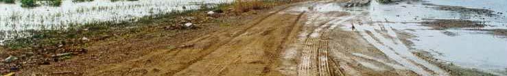
2 EPEC Bang Bo: Works Procedure Gulf of Thailand Construction ti of a 2-km road embankment, 1.33m thick 2
3 Ground Conditions Layer 1: Weathered crust (OC clay) ~ 1-2m thick Layer 2: Soft Bangkok clay (NC clay) ~ 20m thick Layer 3: Firm / stiff clay (overlying alt. sand layers) > 25m 3
4 Engineering Properties Layer 1 C u /σ = 0.2 Layer 2 C u /σ = 0.3 Soft layer 1: 0 10m highly plastic very soft Bangkok clay (av. C r ~ 0.35; av. C v ~ m 2 /y) Soft layer 2: 10 20m soft to medium firm clay 4
5 Potential Problems Final embankment height = 1.33m Fill to compensate settlement = 3m Total fill to be placed = 4.33m 2m Surcharge? Layer 1 (0 10m) C u ~ 4 10 kpa Contract t period of 12 months including consolidation and pavement works. 5
6 Criteria / Concerns LONG TERM CRITERIA Post construction performance ( t = 25 years ): Differential settlement < 1:750 Residual settlement < 40cm Stability : Factor of safety > 1.5 SHORT TERM CONCERNS Stability during construction (most critical) Handover date for turbine & other heavy structures (time constraint) Inadequate local source of fill materials and high price (reduce or eliminate surcharge?) 6


7 Preparation of Working Platform Encounter slip failures and lateral flows! 7


8 Design Scheme & Field Implementation Double drain grid design for layer 1 and layer 2 soft clay. Vacuum depressurization at 60 kpa for 7 months Primary Grid : 1 drain per m 2 ISOTROPIC CONSOLIDATION Secondary Grid :1 drain per 2m 2 8


9 Initial Conditions 9


10 Pre Engineering Tests 10


11 Horizontal Drains Connection 11
12 Installation of Geotechnical Instruments 12
13 Initial Depressurization Initial depressurization of 0.3 bar (30 kpa) achieved in 3-5 days. Then, proceed with embankment construction. 13
14 Advanced Stage of Consolidation 14
15 Settlement Results Settlement: Mean (40) = 2.63m Most critical was embankment remained STABLE! vacuum pumping δs/δt < 0.5mm/day 15
16 Post Treatment Strength After Before Design 16


17 Another Proven Record Before Menard Vacuum 1m fill : FS < 1 During Menard Vacuum 4m fill : FS >
18 1 st Successful Vacuum Project in Thailand Client: EPEC / Consultant: SEATEC / M.Contractor: ABB Alstom 18
19 1 st Successful Vacuum Project in Thailand Total area treated t by MV: 30, m2 Drains: Total length of drains: Equipment: Working time: 600,000 m (V+H drains) 4rigs+2vibro 3 months Vacuum: Pumping equipment: Pumping duration: Average total settlement: 15 pumps 7 months 2.65 m Total working time: 10 months 19
20 Soil Profile 21
21 Future Caisson Stability Analysis 22
22 Exhibited Design 23
23 As built conditions 24
24 Proposed solution Layer I 15% rock (φ = 45 ) + 85% clay (C u = 50 kpa) Layer II 25
25 Shear strength mobilised in exhibited design The upper layer I consists of compacted sand fill of 1.3m thick (ϕ = 35 o ; C = 0) and the lower layer II consists of natural undisturbed clay of 1.5m thick (ϕ = 0 o ; C = 250 kn/m 2 ). Assuming an overburden effective stress (σ ) of 275 kn/m 2, we have the following: Layer I: τ = C + σ tan φ = 275 * tan(35 o ) = 192kN / m 2 Layer II: τ = C + σ tan φ = 250kN / m 2 26
26 Shear strength mobilised for proposed solution The upper layer I consists of compacted rock mat of 1.3m thick with 30% of rock size 150mm to 200mm and 70% of rock size 200mm to 300mm (ϕ = 45 o ; C = 0) and the lower layer II consists of composite rock-clay soil layer of 1.5m thick with an area replacement ratio m = 15%. The rock inclusions with similar grading as above has ϕ r = 45 o (C r = 0) and the surrounding clay soil has C s = 50 kn/m 2 (ϕ s = 0 o ). Taking the same overburden effective stress (σ ) of 275 kn/m 2, we have the following: Case 1: Without considering consolidation effect with no gain in shear strength Layer I: ϕ = 45 o ; C = 0 Layer II: Computation for composite ϕ and C Using equation (7): C = C ( m) + C (1 m) = 50(1 0.15) 42.5kN / m r s = 2 Using equation (10): σ r σ s o tan φ = m tan φ r + (1 m) tan φs = 0.15(2.04) tan σ σ tan φ = ϕ = 17 o (for σ s /σ = 2.04 see calculation on page 8 below) Layer I: Layer II: o τ = C + σ tan φ = 275* tan(45 ) = 275kN / m τ = C + σ tan φ = tan17 o 2 = 127kN / m 2 27
27 Total shear strength for exhibited design and proposed solution 28
28 Criteria retained for pounder design A - 35 tons submerged - 175X meter DR section B Design a stabilisation part that will rest on the side of print and guarantee penetration until stabilising part hits the crater side C Final design with final objective, -penetrating part 1.7 x 1.7 -length of penetration 1.7 m -stabilising part 2.4 x 2.4 m -ironing i i or compaction by turning over the pounder 29
29 View of pounder construction 33
30 Caisson construction yard 34
31 Pontoon PMT Testing 35
32 View of pounder ready to work 36
33 GPS Positionning system and grids 37
34 Quality control screen Liebherr
35 Depth of penetration versus number of blows Penetration Vs Blows 2 Penetratio on, m 1.5 Q2 P3 O4 Q4 Q3 P4 1 O6 Q6 Q5 P6 O5 P5 0.5 O Blows 39
36 Danger of offshore pounding V max of pounder measured by radar 8 m/sec V effective reached after 6 m drop 6 m/sec Weight below water 35 tons V = 2gh 36 = 20 h Equivalent drop height 2 m Equivalent Energy: 70 Tm Compaction Depth According to Classical Formula D = 83m 8,3 If δ = 0,5 D = 4,15 m!!! 40
37 General Set up 43
38 Testing pontoon 44
39 View on staff system 45

40 Self bored slotted tube : first experiment of Menard RETROJET SYSTEM S 46
41 Actual staff systems 47


42 Staff dulling equipment 48
43 Sequences of self boring staff system 49
44 Actual method for drilling PMT in rock mound (100 mm 300 mm) 51
45 Empirical determination of friction angle by PMT (Yee & Varaksin method) * = = C P C P m L m L l l φ φ φ φ * 2 2 φ P = * 2 φ P L 2 log log = m C P C L φ l φ = 4 40 * φ P L = * 2 P L 52
46 Reminder of technical solution SITE CONDITION SITE CONDITION Compacted sand fill Compacted ϕ = 35 ο sand fill ϕ = 35 ο undisturbed soil Variance 15% rock thickness (φ = 45 ) soften + soil 15% rock (φ = 45 ) + undisturbed soil Variance 85% 15% clay (C rock thickness u = (C50 u (φ = kpa) 50= soften kpa) 45 ) soil 85% + 15% clay rock (C u (φ = 50= kpa) 45 ) + 85% clay (C u = (C 50 u = kpa) 50 kpa) 85% clay (C u = 50 kpa) Natural undisturbed soil Natural undisturbed soil Natural undisturbed soil Natural undisturbed soil Natural undisturbed soil Natural undisturbed soil Layer I Layer II 53
47 Preliminary concept Original rock surface before compaction 1.3m φ=45 degree, Ar=15%, C=0kPa, Column Diameter=1.7m 15m 1.5m Cu=50kPa Cu=50kPa Cu=250kPa 54
48 After compaction actual results Original rock surface before compaction 0.2m 1.3m 1.3m φ=48 degree Ar=22% C=0kPa Column Dia=2.4m φ=40 degree φ=48 degree φ=40 degree Ar=22% Cu=50kPa C=0kPa Column Dia=2.4m Cu=50kPa φ=48 degree Ar=22% C=0kPa Column Dia=2.4m Cu=250kPa 55
49 Strength of layer I In summary, layer I and layer II shall have the following characteristics. o Layer I : ϕ = 49 o (harmonic mean value); C = 0, m=0.22 (22% of total area) For column Layer I: ϕ = 40 o ; C = 0, m=0.78 (78% of total t area) For in-between bt columns assuming lowest internal friction angle of 40 o. Layer I: Computation for composite ϕ and C C=0 tanφ comp = m tanφ c + (1 m) tanφ oc = 0.22 tan 49 o tan 40 φ comp =
50 Strength of layer II and total share strength Layer II: Computation for composite ϕ and C C = C ( m ) + C (1 m ) = 50(1 0.22) 39 kn / m r s = 2 σ r σ s o tan φ = m tanφr + (1 m) tanφs = 0.22(1.88) tan σ σ tan φ = 0.48 ϕ = 25.4 o (for σ s /σ = 1.88) Hence, layer I and layer II shall have the shear strength as below: Layer I: τ = C + σ tanφ = concept =275kN/m 2 ) 275* tan(42.2 o ) = 249kN / m 2 (compared with proposed Layer II: τ = C + σ tanφ = tan concept = 127kN/m 2 ) o = 170kN / m 2 (compared with proposed 57
51 Layout of CPT in sand area 59
52 Results of CPT in sand fill after DC Before Dynamic Compaction After Dynamic Compaction 60


53 GROUND IMPROVEMENT WORKSHOP JUNE 2010 PERTH, AUSTRALIA
BRASIL MAY 2010
 ISSMGE TC - 17 221 BRASIL 22-23 MAY 2010 Symposium on New Techniques for Design and Construction in Soft Clays. Vacuum consolidation The environmental friendly consolidation of very soft poluted mud at
Chapter (11) Pile Foundations
 Pile Foundations") Chapter (11) Introduction Piles are structural members that are made of steel, concrete, or timber. They are used to build pile foundations (classified as deep foundations) which cost more than shallow
Chapter (11) Introduction Piles are structural members that are made of steel, concrete, or timber. They are used to build pile foundations (classified as deep foundations) which cost more than shallow
Boreholes. Implementation. Boring. Boreholes may be excavated by one of these methods: 1. Auger Boring 2. Wash Boring 3.
 Implementation Boreholes 1. Auger Boring 2. Wash Boring 3. Rotary Drilling Boring Boreholes may be excavated by one of these methods: 4. Percussion Drilling The right choice of method depends on: Ground
EN Eurocode 7. Section 3 Geotechnical Data Section 6 Spread Foundations. Trevor L.L. Orr Trinity College Dublin Ireland.
 EN 1997 1: Sections 3 and 6 Your logo Brussels, 18-20 February 2008 Dissemination of information workshop 1 EN 1997-1 Eurocode 7 Section 3 Geotechnical Data Section 6 Spread Foundations Trevor L.L. Orr
OP-13. PROCEDURES FOR DESIGN OF EMBANKMENT
 Page 1 of 8 WORK INSTRUCTIONS FOR ENGINEERS TYC Compiled by : LSS Checked by : GSS Approved by : OP-13. PROCEDURES FOR DESIGN OF EMBANKMENT Page of 8 13.0 13.1. OVERALL PROCEDURES This section will briefly
Theory of Shear Strength
 SKAA 1713 SOIL MECHANICS Theory of Shear Strength Prepared by, Dr. Hetty 1 SOIL STRENGTH DEFINITION Shear strength of a soil is the maximum internal resistance to applied shearing forces The maximum or
SI Planning & Laboratory Testing for Hill-Site Development
 SI Planning & Laboratory Testing for Hill-Site Development 21 April 2009 IEM Penang Ir. Tan Yean Chin G&P Geotechnics Sdn Bhd Cameron Highlands, 1961 Genting Highland Tower 1993 Bukit Antarabangsa, 1999
Liquefaction and Foundations
 Liquefaction and Foundations Amit Prashant Indian Institute of Technology Gandhinagar Short Course on Seismic Design of Reinforced Concrete Buildings 26 30 November, 2012 What is Liquefaction? Liquefaction
Chapter 12 Subsurface Exploration
 Page 12 1 Chapter 12 Subsurface Exploration 1. The process of identifying the layers of deposits that underlie a proposed structure and their physical characteristics is generally referred to as (a) subsurface
Cavity Expansion Methods in Geomechanics
 Cavity Expansion Methods in Geomechanics by Hai-Sui Yu School of Civil Engineering, University of Nottingham, U. K. KLUWER ACADEMIC PUBLISHERS DORDRECHT / BOSTON / LONDON TABLE OF CONTENTS Foreword Preface
Chapter (12) Instructor : Dr. Jehad Hamad
 Instructor : Dr. Jehad Hamad") Chapter (12) Instructor : Dr. Jehad Hamad 2017-2016 Chapter Outlines Shear strength in soils Direct shear test Unconfined Compression Test Tri-axial Test Shear Strength The strength of a material is the
Chapter (12) Instructor : Dr. Jehad Hamad 2017-2016 Chapter Outlines Shear strength in soils Direct shear test Unconfined Compression Test Tri-axial Test Shear Strength The strength of a material is the
APPENDIX F CORRELATION EQUATIONS. F 1 In-Situ Tests
 APPENDIX F 1 APPENDIX F CORRELATION EQUATIONS F 1 In-Situ Tests 1. SPT (1) Sand (Hatanaka and Uchida, 1996), = effective vertical stress = effective friction angle = atmosphere pressure (Shmertmann, 1975)
Theory of Shear Strength
 MAJ 1013 ADVANCED SOIL MECHANICS Theory of Shear Strength Prepared by, Dr. Hetty 1 Strength of different materials Steel Concrete Soil Tensile strength Compressive strength Shear strength Complex behavior
Ch 4a Stress, Strain and Shearing
 Ch. 4a - Stress, Strain, Shearing Page 1 Ch 4a Stress, Strain and Shearing Reading Assignment Ch. 4a Lecture Notes Sections 4.1-4.3 (Salgado) Other Materials Handout 4 Homework Assignment 3 Problems 4-13,
Class Principles of Foundation Engineering CEE430/530
 Class Principles of Foundation Engineering CEE430/530 1-1 General Information Lecturer: Scott A. Barnhill, P.E. Lecture Time: Thursday, 7:10 pm to 9:50 pm Classroom: Kaufmann, Room 224 Office Hour: I have
Engineeringmanuals. Part2
 Engineeringmanuals Part2 Engineering manuals for GEO5 programs Part 2 Chapter 1-12, refer to Engineering Manual Part 1 Chapter 13. Pile Foundations Introduction... 2 Chapter 14. Analysis of vertical load-bearing
Central Queensland Coal Project Appendix 4b Geotechnical Assessment. Environmental Impact Statement
 Central Queensland Coal Project Appendix 4b Geotechnical Assessment Environmental Impact Statement GEOTECHNICAL ASSESSMENT OF OPEN CUT MINING ADJACENT TO THE BRUCE HIGHWAY, CENTRAL QUEENSLAND COAL PROJECT
1.5 STRESS-PATH METHOD OF SETTLEMENT CALCULATION 1.5 STRESS-PATH METHOD OF SETTLEMENT CALCULATION
 Module 6 Lecture 40 Evaluation of Soil Settlement - 6 Topics 1.5 STRESS-PATH METHOD OF SETTLEMENT CALCULATION 1.5.1 Definition of Stress Path 1.5. Stress and Strain Path for Consolidated Undrained Undrained
Date: April 2, 2014 Project No.: Prepared For: Mr. Adam Kates CLASSIC COMMUNITIES 1068 E. Meadow Circle Palo Alto, California 94303
 City of Newark - 36120 Ruschin Drive Project Draft Initial Study/Mitigated Negative Declaration Appendix C: Geologic Information FirstCarbon Solutions H:\Client (PN-JN)\4554\45540001\ISMND\45540001 36120
Shear Strength of. Charles Aubeny. Department of Civil Engineering Texas A&M University
 Shear Strength of Shallow Soils Charles Aubeny Associate Professor Department of Civil Engineering Texas A&M University Issues 1. Relevant to practical problems Shallow slopes Organic soils Pipeline embedment
Table 3. Empirical Coefficients for BS 8002 equation. A (degrees) Rounded Sub-angular. 2 Angular. B (degrees) Uniform Moderate grading.
 Rounded Sub-angular. 2 Angular. B (degrees) Uniform Moderate grading.") Hatanaka and Uchida (1996); ' 20N 20 12N 20 ' 45 A lower bound for the above equation is given as; 12N 15 ' 45 Table 3. Empirical Coefficients for BS 8002 equation A Angularity 1) A (degrees) Rounded 0
Hatanaka and Uchida (1996); ' 20N 20 12N 20 ' 45 A lower bound for the above equation is given as; 12N 15 ' 45 Table 3. Empirical Coefficients for BS 8002 equation A Angularity 1) A (degrees) Rounded 0
Expressway Embankment Landslide Treatment Technology for Peat Subgrade
 J. Civil Eng. Architect. Res Vol. 1, No. 3, 2014, pp. 203-210 Received: June 30, 2014; Published: September 25, 2014 Journal of Civil Engineering and Architecture Research Expressway Embankment Landslide
Drawing up of a geotechnical dossier for the stabilization of historical quay walls along the river Scheldt in Antwerp
 Drawing up of a geotechnical dossier for the stabilization of historical quay walls along the river Scheldt in Antwerp Leen Vincke, Koen Haelterman Geotechnics Division Flemish Government, Belgium Leen.vincke@mow.vlaanderen.be
Field and Laboratory Testing of Soil for Surcharge Design
 Field and Laboratory Testing of Soil for Surcharge Design Steven Bartlett. University of Utah Required from Field and Pre-Construction Investigations 1. Design profile and X-sections with natural ground
A. V T = 1 B. Ms = 1 C. Vs = 1 D. Vv = 1
 Geology and Soil Mechanics 55401 /1A (2002-2003) Mark the best answer on the multiple choice answer sheet. 1. Soil mechanics is the application of hydraulics, geology and mechanics to problems relating
Geology and Soil Mechanics /1A ( ) Mark the best answer on the multiple choice answer sheet.
 Mark the best answer on the multiple choice answer sheet.") Geology and Soil Mechanics 55401 /1A (2003-2004) Mark the best answer on the multiple choice answer sheet. 1. Soil mechanics is the application of hydraulics, geology and mechanics to problems relating
Geology and Soil Mechanics 55401 /1A (2003-2004) Mark the best answer on the multiple choice answer sheet. 1. Soil mechanics is the application of hydraulics, geology and mechanics to problems relating
SOME OBSERVATIONS RELATED TO LIQUEFACTION SUSCEPTIBILITY OF SILTY SOILS
 SOME OBSERVATIONS RELATED TO LIQUEFACTION SUSCEPTIBILITY OF SILTY SOILS Upul ATUKORALA 1, Dharma WIJEWICKREME 2 And Norman MCCAMMON 3 SUMMARY The liquefaction susceptibility of silty soils has not received
Landslide FE Stability Analysis
 Landslide FE Stability Analysis L. Kellezi Dept. of Geotechnical Engineering, GEO-Danish Geotechnical Institute, Denmark S. Allkja Altea & Geostudio 2000, Albania P. B. Hansen Dept. of Geotechnical Engineering,
SOME GEOTECHNICAL PROPERTIES OF KLANG CLAY
 SOME GEOTECHNICAL PROPERTIES OF KLANG CLAY Y.C. Tan, S.S. Gue, H.B. Ng 3, P.T. Lee 4 ABSTRACT A series of subsurface investigation including in-situ and laboratory tests has been carefully planned and
vulcanhammer.net This document downloaded from
 This document downloaded from vulcanhammer.net since 1997, your source for engineering information for the deep foundation and marine construction industries, and the historical site for Vulcan Iron Works
INTRODUCTION TO STATIC ANALYSIS PDPI 2013
 INTRODUCTION TO STATIC ANALYSIS PDPI 2013 What is Pile Capacity? When we load a pile until IT Fails what is IT Strength Considerations Two Failure Modes 1. Pile structural failure controlled by allowable
The Bearing Capacity of Soils. Dr Omar Al Hattamleh
 The Bearing Capacity of Soils Dr Omar Al Hattamleh Example of Bearing Capacity Failure Omar Play the move of bearing Capacity failure The Philippine one Transcona Grain Silos Failure - Canada The Bearing
SOIL SHEAR STRENGTH. Prepared by: Dr. Hetty Muhammad Azril Fauziah Kassim Norafida
 SOIL SHEAR STRENGTH Prepared by: Dr. Hetty Muhammad Azril Fauziah Kassim Norafida What is shear strength Shear strength of a soil is the maximum internal resistance to applied shearing forces Why it is
Seabed instability and 3D FE jack-up soil-structure interaction analysis
 Seabed instability and 3D FE jack-up soil-structure interaction analysis Lindita Kellezi, GEO Danish Geotechnical Institute, Denmark Gregers Kudsk, Maersk Contractors, Denmark Hugo Hofstede, Marine Structure
HKIE-GD Workshop on Foundation Engineering 7 May Shallow Foundations. Dr Limin Zhang Hong Kong University of Science and Technology
 HKIE-GD Workshop on Foundation Engineering 7 May 2011 Shallow Foundations Dr Limin Zhang Hong Kong University of Science and Technology 1 Outline Summary of design requirements Load eccentricity Bearing
INTI COLLEGE MALAYSIA
 EGC373 (F) / Page 1 of 5 INTI COLLEGE MALAYSIA UK DEGREE TRANSFER PROGRAMME INTI ADELAIDE TRANSFER PROGRAMME EGC 373: FOUNDATION ENGINEERING FINAL EXAMINATION : AUGUST 00 SESSION This paper consists of
D1. A normally consolidated clay has the following void ratio e versus effective stress σ relationship obtained in an oedometer test.
 (d) COMPRESSIBILITY AND CONSOLIDATION D1. A normally consolidated clay has the following void ratio e versus effective stress σ relationship obtained in an oedometer test. (a) Plot the e - σ curve. (b)
Table of Contents Chapter 1 Introduction to Geotechnical Engineering 1.1 Geotechnical Engineering 1.2 The Unique Nature of Soil and Rock Materials
 Table of Contents Chapter 1 Introduction to Geotechnical Engineering 1.1 Geotechnical Engineering 1.2 The Unique Nature of Soil and Rock Materials 1.3 Scope of This Book 1.4 Historical Development of Geotechnical
Calculation of 1-D Consolidation Settlement
 Calculation of 1-D Consolidation Settlement A general theory for consolidation, incorporating threedimensional flow is complicated and only applicable to a very limited range of problems in geotechnical
Hazard-Mitigation of Civil Infrastructure through. Dynamic Compaction. Kameron Kaine Raburn
 Hazard-Mitigation of Civil Infrastructure through Dynamic Compaction Kameron Kaine Raburn Effects of Liquefaction http://web.ics.purdue.edu/~braile/edumod/eqphotos/eqphotos2_files/image006.jpg http://s.hswstatic.com/gif/earthquake-4.jpg
TC211 Workshop CALIBRATION OF RIGID INCLUSION PARAMETERS BASED ON. Jérôme Racinais. September 15, 2015 PRESSUMETER TEST RESULTS
 Jérôme Racinais September 15, 215 TC211 Workshop CALIBRATION OF RIGID INCLUSION PARAMETERS BASED ON PRESSUMETER TEST RESULTS Table of contents 1. Reminder about pressuremeter tests 2. General behaviour
Reinforced Soil Structures Reinforced Soil Walls. Prof K. Rajagopal Department of Civil Engineering IIT Madras, Chennai
 Geosynthetics and Reinforced Soil Structures Reinforced Soil Walls continued Prof K. Rajagopal Department of Civil Engineering IIT Madras, Chennai e-mail: gopalkr@iitm.ac.inac in Outline of the Lecture
Design of Shallow Foundations for a Large Polysilicon Plant in China
 Missouri University of Science and Technology Scholars' Mine International Conference on Case Histories in Geotechnical Engineering (2013) - Seventh International Conference on Case Histories in Geotechnical
Chapter 5 Shear Strength of Soil
 Page 5 Chapter 5 Shear Strength of Soil. The internal resistance per unit area that the soil mass can offer to resist failure and sliding along any plane inside it is called (a) strength (b) shear strength
Predicting Settlement and Stability of Wet Coal Ash Impoundments using Dilatometer Tests
 Predicting Settlement and Stability of Wet Coal Ash Impoundments using Dilatometer Tests Chris Hardin, P.E. CH2M Hill, Charlotte, North Carolina, E-mail: Chris.Hardin@ch2m.com Roger Failmezger, P.E., F.
Chapter (5) Allowable Bearing Capacity and Settlement
 Allowable Bearing Capacity and Settlement") Chapter (5) Allowable Bearing Capacity and Settlement Introduction As we discussed previously in Chapter 3, foundations should be designed for both shear failure and allowable settlement. So the allowable
Chapter (5) Allowable Bearing Capacity and Settlement Introduction As we discussed previously in Chapter 3, foundations should be designed for both shear failure and allowable settlement. So the allowable
Prof. B V S Viswanadham, Department of Civil Engineering, IIT Bombay
 19 Module 5: Lecture -1 on Stability of Slopes Contents Stability analysis of a slope and finding critical slip surface; Sudden Draw down condition, effective stress and total stress analysis; Seismic
Rock Berm Restraint of an Untrenched Pipeline on Soft Clay
 Rock Berm Restraint of an Untrenched Pipeline on Soft Clay J.-C. Ballard, P.H. Yonatan and M.J. Rattley, Fugro GeoConsulting A. Griffiths, Shell UK Limited ABSTRACT This paper discusses soil structure
Effects of Slope Stability Evaluation on Highway Bridge Design
 Effects of Slope Stability Evaluation on Highway Bridge Design Shanzhi Shu, PhD PE KCI Technologies INC Les C. Banas, PE Kiewit Infrastructure Engineers Samuel D. Palmer, PE Terracon Consultants Inc. Introduction
3-BEARING CAPACITY OF SOILS
 3-BEARING CAPACITY OF SOILS INTRODUCTION The soil must be capable of carrying the loads from any engineered structure placed upon it without a shear failure and with the resulting settlements being tolerable
Geotechnical Parameters for Retaining Wall Design
 11 th October 2012 Geotechnical Parameters for Retaining Wall Design Tanya Kouzmin 1 Most geotechnical failures are of retaining walls Are failure caused by WRONG calculations? Not usually calculation
The attitude he maintains in his relation to the engineer is very well stated in his own words:
 Su bsurface Soil Exploration, 53: 139 Foundation Engineering Geotechnical companies that have a history of experience in a given region usually have extensive boring logs and maps telling where the borings
YOUR HW MUST BE STAPLED YOU MUST USE A PENCIL (no pens)
") Spring 2008 CIVE 462 HOMEWORK #1 1. Print out the syllabus. Read it. Write the grade percentages in the first page of your notes. 2. Go back to your 301 notes, internet, etc. and find the engineering definition
Spring 2008 CIVE 462 HOMEWORK #1 1. Print out the syllabus. Read it. Write the grade percentages in the first page of your notes. 2. Go back to your 301 notes, internet, etc. and find the engineering definition
Cyclic Triaxial Testing of Water-Pluviated Fly Ash Specimens
 2013 World of Coal Ash (WOCA) Conference - April 22-25, 2013 in Lexington, KY http://www.flyash.info/ Cyclic Triaxial Testing of Water-Pluviated Fly Ash Specimens Jeffrey S. Dingrando 1, Michael E. Kalinski
PRINCIPLES OF GEOTECHNICAL ENGINEERING
 PRINCIPLES OF GEOTECHNICAL ENGINEERING Fourth Edition BRAJA M. DAS California State University, Sacramento I(T)P Boston Albany Bonn Cincinnati London Madrid Melbourne Mexico City New York Paris San Francisco
CHARACTERIZATION OF SOFT CLAY- A CASE STUDY AT CRANEY ISLAND
 National Defense Industrial Association 2005 Tri-Service Infrastructure Systems Conference and Exhibition Re-Energizing Engineering Excellence CHARACTERIZATION OF SOFT CLAY- A CASE STUDY AT CRANEY ISLAND
GEOTECHNICAL EVALUATION AND GEOTECHNICAL DESIGN PARAMETERS)
") -1-3_Geotechnical investigation and evaluation - Geotechnical parameters of formations (Relevant paragraph of the paper: GEOTECHNICAL EVALUATION AND GEOTECHNICAL DESIGN PARAMETERS) The soil stratigraphy
-1-3_Geotechnical investigation and evaluation - Geotechnical parameters of formations (Relevant paragraph of the paper: GEOTECHNICAL EVALUATION AND GEOTECHNICAL DESIGN PARAMETERS) The soil stratigraphy
The San Jacinto Monument Case History
 Picture obtained from http://www.laanba.net/photoblog/ January05/sanjacinto.jpg Jean-Louis Briaud Texas A&M University The San Jacinto Monument Case History 1 2 CREDITS Phillip King Fugro Briaud J.-L.,
water proofing will relatively long time fully completed) be provided 10 storey building (15x25m) original GWT position 1 sat = 20 kn/m 3
 be provided 10 storey building (15x25m) original GWT position 1 sat = 20 kn/m 3") P1 Question: An excavation will be made for a ten storey 15x25 m building. Temporary support of earth pressure and water pressure will be made by deep secant cantilever pile wall. The gross pressure due
P1 Question: An excavation will be made for a ten storey 15x25 m building. Temporary support of earth pressure and water pressure will be made by deep secant cantilever pile wall. The gross pressure due
ENCE 3610 Soil Mechanics. Site Exploration and Characterisation Field Exploration Methods
 ENCE 3610 Soil Mechanics Site Exploration and Characterisation Field Exploration Methods Geotechnical Involvement in Project Phases Planning Design Alternatives Preparation of Detailed Plans Final Design
Developing a more accurate description of soil-pipe interaction for the design of high temperature pipelines
 Background references Developing a more accurate description of soil-pipe interaction for the design of high temperature pipelines David White Shell EMI Professor of Offshore Engineering Fraser Bransby
8.1. What is meant by the shear strength of soils? Solution 8.1 Shear strength of a soil is its internal resistance to shearing stresses.
 8.1. What is meant by the shear strength of soils? Solution 8.1 Shear strength of a soil is its internal resistance to shearing stresses. 8.2. Some soils show a peak shear strength. Why and what type(s)
both an analytical approach and the pole method, determine: (a) the direction of the
 the direction of the") Quantitative Problems Problem 4-3 Figure 4-45 shows the state of stress at a point within a soil deposit. Using both an analytical approach and the pole method, determine: (a) the direction of the principal
Quantitative Problems Problem 4-3 Figure 4-45 shows the state of stress at a point within a soil deposit. Using both an analytical approach and the pole method, determine: (a) the direction of the principal
Shear Strength of Soils
 Shear Strength of Soils STRESSES IN A SOIL ELEMENT t s v Analyze Effective Stresses (s ) Load carried by Soil t Where: s H t t s H s = t f = s v = s H = t = s v Stresses in a Soil Element after Figure
PERFORMANCE OF BITUMINOUS COATS IN REDUCING NEGATIVE SKIN
 PERFORMANCE OF BITUMINOUS COATS IN REDUCING NEGATIVE SKIN FRICTION Makarand G. Khare, PhD Research Scholar, Indian Institute of Technology Madras, Chennai, India Shailesh R. Gandhi, Professor, Indian Institute
Prof. Dr.-Ing. Martin Achmus Institute of Soil Mechanics, Foundation Engineering and Waterpower Engineering. Offshore subsoil investigations
 Prof. Dr.-Ing. Martin Achmus Institute of Soil Mechanics, Foundation Engineering and Waterpower Engineering Offshore subsoil investigations Addis Ababa, September 2010 Offshore subsoil investigations Presentation
Chapter 7 GEOMECHANICS
 Chapter 7 Final SCDOT GEOTECHNICAL DESIGN MANUAL August 2008 Table of Contents Section Page 7.1 Introduction...7-1 7.2 Geotechnical Design Approach...7-1 7.3 Geotechnical Engineering Quality Assurance...7-2
(C) Global Journal of Engineering Science and Research Management
 Global Journal of Engineering Science and Research Management") GEOTECHNCIAL ASSESSMENT OF PART OF PORT HARCOURT, NIGER DELTA FOR STRUCTURAL ANALYSIS Warmate Tamunonengiyeofori Geostrat International Services Limited, www.geostratinternational.com. *Correspondence
GEOTECHNCIAL ASSESSMENT OF PART OF PORT HARCOURT, NIGER DELTA FOR STRUCTURAL ANALYSIS Warmate Tamunonengiyeofori Geostrat International Services Limited, www.geostratinternational.com. *Correspondence
The CPT in unsaturated soils
 The CPT in unsaturated soils Associate Professor Adrian Russell (UNSW) Mr David Reid (Golder Associates) Prof Nasser Khalili (UNSW) Dr Mohammad Pournaghiazar (UNSW) Dr Hongwei Yang (Uni of Hong Kong) Outline
Following are the results of four drained direct shear tests on an overconsolidated clay: Diameter of specimen 50 mm Height of specimen 25 mm
 444 Chapter : Shear Strength of Soil Example. Following are the results of four drained direct shear tests on an overconsolidated clay: Diameter of specimen 50 mm Height of specimen 5 mm Normal Shear force
Analysis of shear strength of armourstone based on 1 m 3 direct shear tests
 Coastal Engineering 341 Analysis of shear strength of armourstone based on 1 m 3 direct shear tests J. Estaire & C. Olalla Laboratorio de Geotecnia (CEDEX, Mº de Fomento) Madrid, Spain Abstract In this
Analysis of Load-Settlement Relationship for Unpaved Road Reinforced with Geogrid
 ISGSR7 First International Symposium on Geotechnical Safety & Risk Oct. 8~9, 7 Shanghai Tongji University, China Analysis of Load-Settlement Relationship for Unpaved Road Reinforced with Geogrid Y. C.
EAS 664/4 Principle Structural Design
 UNIVERSITI SAINS MALAYSIA 1 st. Semester Examination 2004/2005 Academic Session October 2004 EAS 664/4 Principle Structural Design Time : 3 hours Instruction to candidates: 1. Ensure that this paper contains
Cone Penetration Test (CPT) Interpretation
 Interpretation") Cone Penetration Test (CPT) Interpretation Gregg uses a proprietary CPT interpretation and plotting software. The software takes the CPT data and performs basic interpretation in terms of soil behavior
Cone Penetration Test (CPT) Interpretation Gregg uses a proprietary CPT interpretation and plotting software. The software takes the CPT data and performs basic interpretation in terms of soil behavior
Geotechnical Aspects of the Seismic Update to the ODOT Bridge Design Manual. Stuart Edwards, P.E Geotechnical Consultant Workshop
 Geotechnical Aspects of the Seismic Update to the ODOT Bridge Design Manual Stuart Edwards, P.E. 2017 Geotechnical Consultant Workshop Changes Role of Geotechnical Engineer Background Methodology Worked
BEARING CAPACITY SHALLOW AND DEEP FOUNDATIONS
 BEARING CAPACITY SHALLOW AND DEEP FOUNDATIONS CONTENTS: 1.0 INTRODUCTION 2.0 SHALLOW FOUNDATIONS 2.1 Design criteria 2.2 Spreading load 2.3 Types of foundations 2.4 Ground failure modes 2.5 Definitions
Modified Dry Mixing (MDM) a new possibility in Deep Mixing
 a new possibility in Deep Mixing") Modified Dry Mixing (MDM) a new possibility in Deep Mixing Hercules Geo-Trans 2004 1 Structure of presentation 1. The MDM process 2. The MDM system new possibilities 3. Major advantages 4. Field tests
Modified Dry Mixing (MDM) a new possibility in Deep Mixing Hercules Geo-Trans 2004 1 Structure of presentation 1. The MDM process 2. The MDM system new possibilities 3. Major advantages 4. Field tests
Collapsible Soils Definitions
 Collapsible Soils Definitions Collapsible soils are also known as metastable soils. They are unsaturated soils that undergo a large volume change upon saturation. The sudden and usually large volume change
The Ohio Department of Transportation Office of Research & Development Executive Summary Report
 The Ohio Department of Transportation Office of Research & Development Executive Summary Report Shear Strength of Clay and Silt Embankments Start Date: January 1, 2007 Duration: 2 Years- 10 Months Completion
Pressuremeter for Design and Acceptance of Challenging Ground Improvement Works
 th Proceedings of the 18 International Conference on Soil Mechanics and Geotechnical Engineering, Paris 2013 Pressuremeter for Design and Acceptance of Challenging Ground Improvement Works Le pressiomètre
ISC 5 SELF-BORING PRESSUREMETER TESTS AT THE NATIONAL FIELD TESTING FACILITY, BALLINA 5 9 SEPT 2016
 ISC 5 5 9 SEPT 2016 SELF-BORING PRESSUREMETER TESTS AT THE NATIONAL FIELD TESTING FACILITY, BALLINA Fillippo Gaone James Doherty Susan Gourvenec Centre for Offshore Foundation Systems, UWA School of Civil,
STUDY ON CONSOLIDATION OF ALLUVIAL CLAY IN NORTHERN QUEENSLAND
 STUDY ON CONSOLIDATION OF ALLUVIAL CLAY IN NORTHERN QUEENSLAND Barry Wai Choo, Kok Geotechnical Services Manager, Abigroup Australia Dr. Richard Gong Senior Geotechnical Engineer, AECOM Australia ABSTRACT
Shear strength model for sediment-infilled rock discontinuities and field applications
 Shear strength model for sediment-infilled rock discontinuities and field applications Buddhima Indraratna 1, Wuditha Premadasa 2, Jan Nemcik 3 and Mylvaganam Jayanathan 4 1 Centre for Geomechanics and
B-1 BORE LOCATION PLAN. EXHIBIT Drawn By: 115G BROOKS VETERINARY CLINIC CITY BASE LANDING AND GOLIAD ROAD SAN ANTONIO, TEXAS.
 N B-1 SYMBOLS: Exploratory Boring Location Project Mngr: BORE LOCATION PLAN Project No. GK EXHIBIT Drawn By: 115G1063.02 GK Scale: Checked By: 1045 Central Parkway North, Suite 103 San Antonio, Texas 78232
GEOTECHNICAL INVESTIGATION REPORT
 GEOTECHNICAL INVESTIGATION REPORT SOIL INVESTIGATION REPORT FOR STATIC TEST FACILITY FOR PROPELLANTS AT BDL, IBRAHIMPATNAM. Graphics Designers, M/s Architecture & Engineering 859, Banjara Avenue, Consultancy
CPT Guide 5 th Edition. CPT Applications - Deep Foundations. Gregg Drilling & Testing, Inc. Dr. Peter K. Robertson Webinar # /2/2013
 Gregg Drilling & Testing, Inc. Site Investigation Experts CPT Applications - Deep Foundations Dr. Peter K. Robertson Webinar #6 2013 CPT Guide 5 th Edition Robertson & Cabal (Robertson) 5 th Edition 2012
SHEAR STRENGTH OF SOIL
 Soil Failure Criteria SHEAR STRENGTH OF SOIL Knowledge about the shear strength of soil important for the analysis of: Bearing capacity of foundations, Slope stability, Lateral pressure on retaining structures,
SITE INVESTIGATION 1
 SITE INVESTIGATION 1 Definition The process of determining the layers of natural soil deposits that will underlie a proposed structure and their physical properties is generally referred to as site investigation.
Introduction to Soil Mechanics Geotechnical Engineering-II
 Introduction to Soil Mechanics Geotechnical Engineering-II ground SIVA Dr. Attaullah Shah 1 Soil Formation Soil derives from Latin word Solum having same meanings as our modern world. From Geologist point
Soil type identification and fines content estimation using the Screw Driving Sounding (SDS) data
 data") Mirjafari, S.Y. & Orense, R.P. & Suemasa, N. () Proc. th NZGS Geotechnical Symposium. Eds. GJ Alexander & CY Chin, Napier Soil type identification and fines content estimation using the Screw Driving Sounding
Mirjafari, S.Y. & Orense, R.P. & Suemasa, N. () Proc. th NZGS Geotechnical Symposium. Eds. GJ Alexander & CY Chin, Napier Soil type identification and fines content estimation using the Screw Driving Sounding
Geotechnical Investigation and Monitoring Results of a Landslide Failure at Southern Peninsular Malaysia (Part 1: Investigating Causes of Failure)
") Geotechnical Investigation and Monitoring Results of a Landslide Failure at Southern Peninsular Malaysia (Part 1: Investigating Causes of Failure) Liew, S. S., Gue, S. S., Liong, C. H. Director, Gue &
Geotechnical Investigation and Monitoring Results of a Landslide Failure at Southern Peninsular Malaysia (Part 1: Investigating Causes of Failure) Liew, S. S., Gue, S. S., Liong, C. H. Director, Gue &
FUNDAMENTALS SOIL MECHANICS. Isao Ishibashi Hemanta Hazarika. >C\ CRC Press J Taylor & Francis Group. Taylor & Francis Group, an Informa business
 SOIL MECHANICS FUNDAMENTALS Isao Ishibashi Hemanta Hazarika >C\ CRC Press J Taylor & Francis Group Boca Raton London New York CRC Press is an imprint of the Taylor & Francis Group, an Informa business
CHARACTERISTICS OF VACUUM CONSOLIDATION COMPARING WITH SURCHARGE LOAD INDUCED CONSOLIDATION
 International Symposium on Geotechnical Engineering, Ground Improvement and Geosynthetics for Human Security and Environmental preservation, Bangkok, Thailand CHARACTERISTICS OF VACUUM CONSOLIDATION COMPARING
Session 3 Mohr-Coulomb Soil Model & Design (Part 2)
") Mohr Coulomb Model Session 3 Mohr-Coulomb Soil Model & Design (Part 2) Time Session Topic 09:00 10:30 1 Overview 10:30 11:00 Coffee Break 11:00 12:30 2 Design (Part 1) 12:30-01:30 Lunch 01:30 03:00 3 Mohr-Coulomb
Mohr Coulomb Model Session 3 Mohr-Coulomb Soil Model & Design (Part 2) Time Session Topic 09:00 10:30 1 Overview 10:30 11:00 Coffee Break 11:00 12:30 2 Design (Part 1) 12:30-01:30 Lunch 01:30 03:00 3 Mohr-Coulomb
Foundation Engineering Prof. Dr. N. K. Samadhiya Department of Civil Engineering Indian Institute of Technology Roorkee
 Foundation Engineering Prof. Dr. N. K. Samadhiya Department of Civil Engineering Indian Institute of Technology Roorkee Module - 01 Lecture - 01 Shallow Foundation (Refer Slide Time: 00:19) Good morning.
ROCK EXCAVATION (GRADING) OPSS 206 INDEX
 OPSS 206 INDEX") 206-2 - OPSS 206 INDEX 206-2.1 GENERAL 206-2.1.1 Classification of Rock Materials 206-2.1.2 Tender Items 206-2.1.3 Other Excavation Tender Items 206-2.1.4 Specifications 206-2.1.5 Special Provisions 206-2.1.6
206-2 - OPSS 206 INDEX 206-2.1 GENERAL 206-2.1.1 Classification of Rock Materials 206-2.1.2 Tender Items 206-2.1.3 Other Excavation Tender Items 206-2.1.4 Specifications 206-2.1.5 Special Provisions 206-2.1.6
Geotechnical verification of impact compaction
 PII-73 Geotechnical verification of impact compaction P. J. Waddell1, R. A. Moyle2 & R. J. Whiteley1 1 2 Coffey Geotechnics, Sydney, Australia Coffey Geotechnics, Harrogate, UK Abstract Remediation of
 Soil Investigation Report For Construction of District Court Building Near IDA Sch. No. 140, Pipliyahana Talab, Indore (M.P.) Submitted to Divisional Project Engineer MP Public Work Department. Project
Foundation Analysis LATERAL EARTH PRESSURE
 Foundation Analysis LATERAL EARTH PRESSURE INTRODUCTION Vertical or near-vertical slopes of soil are supported by retaining walls, cantilever sheet-pile walls, sheet-pile bulkheads, braced cuts, and other
A Comparative Study on Bearing Capacity of Shallow Foundations in Sand from N and /
 DOI 10.1007/s40030-017-0246-7 ORIGINAL CONTRIBUTION A Comparative Study on Bearing Capacity of Shallow Foundations in Sand from N and / V. A. Sakleshpur 1 C. N. V. Satyanarayana Reddy 1 Received: 9 January