Session 3 Mohr-Coulomb Soil Model & Design (Part 2)
|
|
|
- Aldous Owens
- 5 years ago
- Views:
Transcription
1 Mohr Coulomb Model Session 3 Mohr-Coulomb Soil Model & Design (Part 2) Time Session Topic 09:00 10:30 1 Overview 10:30 11:00 Coffee Break 11:00 12:30 2 Design (Part 1) 12:30-01:30 Lunch 01:30 03:00 3 Mohr-Coulomb Soil Model & Design (Part 2) 03:00 03:30 Coffee Break 03:30 05:00 4 How to reduce wall deflection Mohr Coulomb Model 1 Things you should know about the Mohr Coulomb Soil Model Plastic Elasticplastic Elastic ε ε Mohr Coulomb Model 2 Wong Kai Sin 1
2 Mohr Coulomb Model Can Mohr Coulomb Model simulate Real Soil Behaviour? UU Test on Clay Plastic c u > 0 φ u = 0 Elasticplastic Elastic ε ε CD Test on Clay or Sand Plastic c' 0 φ' > 0 ε Elastic ε Real Soil Mohr Coulomb Soil Mohr Coulomb Model 3 Can a Elastic Model simulate Real Soil Behaviour? Elastic Model Shearstress produces Normalstress produces shear strain: volumetric strain: τ γ ε v τ no ε v Mohr Coulomb Model 4 Wong Kai Sin 2
3 Mohr Coulomb Model Can a elastic soil simulate undrained behaviour of clay? τ Plastic Elastic ε ε Real Soil Behaviour τ γ τ no ε v no ε v (undrained) Stress independent Elastic Model (ν=0.5) τ γ τ no ε v no ε v (undrained) Stress independent Mohr Coulomb Model 5 Can a elastic soil simulate undrained behaviour of clay? τ Plastic Elasticplastic Elasticplastic Elastic ε ε Yes! If we use c u and E u. Can we use c' φ' and E'? Mohr Coulomb Model 6 Wong Kai Sin 3

4 Mohr Coulomb Model CU Test 100 ESP TSP p or p (kpa) Mohr Coulomb Model 7 CU Test Consolidated Undrained Triaxial Compression Test = 100 kpa Real Soil Mohr Coulomb 1 3 ε curve q K f q 2c u K f c u from c' φ' 2c u ESP TSP ESP TSP c u measured p or p p or p c' φ' over predicted c u!!! Mohr Coulomb Model 8 ε 1 Wong Kai Sin 4
5 Mohr Coulomb Model Is the pore pressure response correct? Let s look at CU test on a normally consolidated clay. Real Soil Elastic Soil q K f q Kf U f U f ESP TSP ESP TSP p or p p or p The predicted pore pressure is much smaller than the measured! Mohr Coulomb Model 9 Method A Effective stress Mohr Coulomb Method using c and φ It over estimates the undrained shear strength and under estimates the excess pore pressure of a normally consolidated clay. Real Soil Elastic Soil q K f q 2c u Kf 2c u U f U f ESP TSP ESP TSP p or p p or p Mohr Coulomb Model 10 Wong Kai Sin 5
 Reduced")
6 Mohr Coulomb Model Over estimation of c u at a Reclaimed Site Depth (m) Undrained Shear Strength (kpa) Method A (qt-po)/nkt 0.22*p'o corr. FVT Consol tests Cu based on phi=22 & p'o Mohr Coulomb Model 11 Nicoll Highway Results of Undrained Analysis using Method A Computed using Method A Measured Reduced Level (m) Reduced Level (m) Level mm Formation = 118 mm Final = 145 mm Wall Deflection (mm) Mohr Coulomb Model 12 Wong Kai Sin 6
7 Mohr Coulomb Model Does Method Aalways over estimate c u for NC clay? ( 1 3 ) f τ φ' 1 3 This site has a constant c u. ε c u A B C φ u =0 ' For NC Clay, it under estimates c u at low stress and over estimates it at high stress. Mohr Coulomb Model 13 Method B Effective stress Mohr Coulomb Method using c u and φ u =0 It forces the soil to fail at a specified undrained shear strength. Real Soil Elastic Soil q K f q 2c u 2c u K f ESP TSP ESP TSP p or p p or p Mohr Coulomb Model 14 Wong Kai Sin 7


8 Mohr Coulomb Model Nicoll Highway Results of Undrained Analysis using Method B Computed using Method B Measured Mohr Coulomb Model 15 Can Method Abe used for Overconsolidated Clay? ( 1 3 ) f C τ CU 1 φ' B 3 A c φ u =0 u UU This site has a c' constant c u. ε A B C ' For a given layer of OC Clay, it under estimates c u at low stress and over estimates it at high stress. Mohr Coulomb Model 16 Wong Kai Sin 8
9 Mohr Coulomb Model Using Method A for Undrained Analysis in OC Clay Real Soil Elastic Soil q 2c u K f q 2c u K f U f U f ESP TSP ESP TSP p or p p or p 1. Make sure the measured stress path is similar to that of Elastic Soil. 2. Divide the stratum into sub layers with different c and φ for each layer. 3. Compute c u from c and φ for each layer. Make sure the values are reasonable. Mohr Coulomb Model 17 Using Mohr Coulomb model for Undrained Analysis Method A c' and φ' produces wrong c u for NC clay, but it may produce correct c u for OC clay Method B or C Forces Plaxis to use specified c u Method A Method B Method C Stress Type Effective Effective Total Strength c and φ c u and φ u c u and φ u Modulus E E E u Poisson s Ratio ν ν = 0.35 ν u = K o or K ot K o K o K ot Mohr Coulomb Model 18 Wong Kai Sin 9
10 ) Mohr Coulomb Model Can MC model simulate undrained behaviour of clay? τ Elastic plastic Plastic Inelastic Elastic ε ε 1. It produces the correct strength with c u specified. 2. It cannot simulate non linear and inelastic behaviour. 3. It may not generate reliable pore pressure response. Mohr Coulomb Model 19 Can M C model generate accurate deflection profiles at every stage of excavation? Constant E ε Wall Deflection (mm) Depth (m Mohr Coulomb Model 20 Wong Kai Sin 10
11 Mohr Coulomb Model At early stage of excavation, Mohr Coulomb, Linear E larger δ Hyperbolic, Non linear E smaller δ E t Mohr Coulomb Model 21 At final stage of excavation, Mohr Coulomb, Linear E smaller δ Hyperbolic, Non linear E larger δ E t Nonlinear Linear Mohr Coulomb Model 22 Wong Kai Sin 11
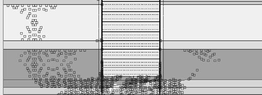
12 Mohr Coulomb Model Mohr Coulomb E u /c u ~ 100 to 500 Constant E ε Conclusion M C model may not produce good match at every stage of excavation. Advanced Soil Model Mohr Coulomb Model 23 ε How reliable are the results generated by the MC model? Soft MarineClay Fill ε δ V,MAX = 33 mm δ H,MAX = 28 mm Is the mode of deformation reasonable? Mohr Coulomb Model 24 Wong Kai Sin 12
13 Mohr Coulomb Model Results using Hyperoblic Model Soft MarineClay Fill ε δ V,MAX = 72 mm δ H,MAX = 59 mm Is the mode of deformation reasonable? Mohr Coulomb Model 25 Linear vs Non Linear Soft Marine Clay Fill ε Mohr Coulomb Model 26 ε Wong Kai Sin 13
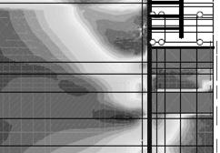
14 Mohr Coulomb Model Check plastic points and relative shear stress! Fill Soft Marine Clay Lesson learned: Correct analysis may not produce correct results. Mohr Coulomb Model 27 Linear vs Non Linear Model Mohr Coulomb Model Real Soil Behaviour E 2 E 3 E4 E 2 E 1 Constant E ε ε You must understand the shortcomings of the soil model used! Mohr Coulomb Model 28 Wong Kai Sin 14


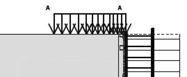
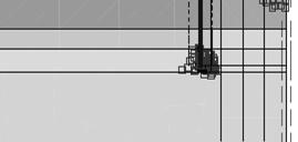
15 Mohr Coulomb Model Using Method B at Reclaimed Site Fill Soft Marine Clay Sandy Silt Method B is an effective stress method. K o = 1 sin φ' If clay is still consolidating, the computed relative shear stress will be > 1, i.e. the clay is in failure state prior to excavation. Mohr Coulomb Model 29 Using effective K o at a site still undergoing consolidation Plastic points Mohr Coulomb Model 30 Wong Kai Sin 15
16 Mohr Coulomb Model Method B (c u φ u ) and K o (1 sin φ) Reduced Level (m) B Current effective stress Effective overburden pressure A Current Effective Stress (kpa) Fill Soft Marine Clay Sandy Silt At A, (' V ' H ) = ' V (1 K o ) = 74 kpa At B, (' V ' H ) = ' V (1 K o ) = 37 kpa Current c u = 22 kpa ( 1 3 ) f = 2 c u = 44 kpa Mohr Coulomb Model 31 Need to set the correct initial stresses! Fill Soft Marine Clay Sandy Silt Check plastic points after generating the initial stresses! Mohr Coulomb Model 32 Wong Kai Sin 16
17 Mohr Coulomb Model Mohr Coulomb Model 33 Mohr Coulomb Model 34 Wong Kai Sin 17
18 Mohr Coulomb Model Stress Dependent Behaviour of Soil under Drained Condition ε Mohr Coulomb Model 35 Stress Paths in an Elastic Medium D C K o B F E Δ 1 Δ 3 A E Questionable Zone F Danger Zone 3 Mohr Coulomb Model 36 Wong Kai Sin 18
19 Mohr Coulomb Model Typical Stress Paths in Excavation A B B A Mohr Coulomb Model 37 Stress Path in Zone F under Drained Condition rubber soil ε 1 (%) ε v (%) Mohr Coulomb Model 38 Wong Kai Sin 19
20 Mohr Coulomb Model Stress Path in Zone E under Drained Condition 1 =300 3 =300 Mohr Coulomb Model 39 A drained analysis can produce incorrect results under certain stress path. Which one is correct? A B A B ε Measured Computed Lesson learned: Correct analysis may not produce correct results! Mohr Coulomb Model 40 Wong Kai Sin 20
21 Mohr Coulomb Model Some problems may be sensitive to Poisson s Ratio ν=0.2 c =5 kpa φ =35 o E =8000 kpa H=9 m ν=0.4 M max,knm/m Strut 1, kn/m Strut 2, kn/m Strut 3, kn/m D epth ( m ) Wall Deflection (mm) ν=0.2 Pois. Ratio = 0.2 Lesson learned: Drained analysis can produce many surprises. ν=0.4 Pois. Ratio = 0.4 Mohr Coulomb Model 41 Can MC model simulate drained behaviour of soil? 1. It gives correct strength τ f = c + tan φ 2. Modulus is not stress dependent. 3. It cannot simulate non linear and inelastic behaviour. 4. It may produce wrong response in certain stress path. 5. Results may be sensitive to Poisson s ratio. Mohr Coulomb Model 42 Wong Kai Sin 21
22 Mohr Coulomb Model Can MC model simulate drained behaviour of soil? ε v Elastic Plastic ε 6. It may not produce correct pore pressure response. 7. When using c' φ' in consolidation analysis, it may generate the wrong undrained strength at end of construction. 8. There is no dilation until after the soil reaches failure. Mohr Coulomb Model 43 Mohr Coulomb Model 44 Wong Kai Sin 22
23 Designing Temporary Work Design & Analysis Instrumentation Monitoring Construction Control Designing Temporary Work is a Continuous Process Initial Design (Working Drawings) Start Excavation Final Design (As-Built) Finish 1 Types of Analysis in TERS Design 1. Analysis for preliminary design 2. Analysis for working design to be adopted in construction 3. Back-analysis 4. Re-analysis Prelim. Design Working Design Back-Analysis & Re-analysis Final Design (As-Built) Start Excavation Finish 2 Wong Kai Sin 1
24 Analysis for preliminary design To assess feasibility of proposed TERS configuration and construction sequence. To assess effect of excavation on surrounding structures To conduct analysis using moderately conservative design parameters 3 Analysis for working or Final design to be adopted in construction To conduct sensitivity studies assessing the effect of variable uncertainties To finalise the strut forces and wall bending moments for structural design To assess the risk of damage to adjacent structures 4 Wong Kai Sin 2
25 Back-Analysis during Construction To be carried out when the field performance is much better or worse than anticipated. To calibrate the design parameters against field measurements Wall Deflection (mm) Computed Depth (m) Measured Re-Analysis during Construction To be carried out after back-analysis To assess potential final outcome using calibrate design parameters To revise the design where appropriate Wall Deflection (mm) Wall Deflection (mm) Depth (m) Computed Design Measured Back-Analyzed Depth (m) Wong Kai Sin 3
26 Overview of Design Process 1. Site investigation 2. Pre-construction survey 3. Evaluation of soil conditions 4. Selection of TERS configuration 5. Assessment of system stability 6. Preparation for FEA 7. Assessment of computed output 7 Design Step 1: Site Investigation Plan View 1. Site investigation 2. Pre-construction survey 3. Evaluation of soil conditions 4. Selection of TERS configuration 5. Assessment of system stability 6. Preparation for FEA 7. Assessment of computed output Sectional View Designer must be actively involved in the site investigation. Get the best S.I. company to do the job! Do enough borings and CPTs. 8 Wong Kai Sin 4


27 2. Pre-Construction Survey To check pre-existing conditions of surrounding structures Things you can see.. Cracks Patches under new paint Settlement of aprons & driveway Constructions in the vicinity 1. Site investigation 2. Pre-construction survey 3. Evaluation of soil conditions 4. Selection of TERS configuration 5. Assessment of system stability 6. Preparation for FEA 7. Assessment of computed output A comprehensive pre-con survey provides the designer with a proper perspective of the surrounding and issues that must be considered in the design Wong Kai Sin 5
28 Pre-Construction Survey Pre-existing Conditions Things you can t see.. Ongoing movements Seasonal fluctuations Ground settlement profile Invest in Instrumentation Settlement marks Paper prisms Water standpipes Inclinometers Evaluation of Soil Conditions Things to check.. Fill thickness and variations Soft clay thickness and variations State of consolidation of soft clay Depth to hard stratum & variations Ground water table 1. Site investigation 2. Pre-construction survey 3. Evaluation of soil conditions 4. Selection of TERS configuration 5. Assessment of system stability 6. Preparation for FEA 7. Assessment of computed output Fill Soft Marine Clay Stiff Silty Clay Dense Silt Sand 12 Wong Kai Sin 6
29 Design Soil Profile & Parameters Fill Upper Marine Clay Intermediate Stiff Clay Lower Marine Clay Old Alluvium Extract only the reliable facts from Factual Report. Is the soil condition uniform? Can we use half mesh? 13 Example on Idealised Soil Profile ABH-30 M3010 Worst soil condition ABH-32 Instrumented section AC-3 ABH-84 ABH-31 Soil Profile at ABH-32 adopted in Original Design 14 Wong Kai Sin 7
 UMC F2 upper UMC F2 upper 85.4 LMC 69.4 63.7 61.2 59.2 55.")
30 Example on Soil Profile -- Half-mesh based on ABH-32 Fill E upper UM C F2 upper LMC RL (m) JGP1 JGP2 E lower F2 lower 61. OA N = OA N = Example on Soil Profile Full-mesh at Instrumented Section ABH-84 Fill E M3010 Fill E RL (m) UMC F2 upper UMC F2 upper 85.4 LMC LMC F2 lower OA N = 20 OA N = 30 OA N = 70 JGP1 LMC JGP F2 F2 lower JGP3 OA N = 20 OA N = OA N = OA N = Wong Kai Sin 8


31 Example -- Results can be very sensitive to variations in soil profile C B Cross-Over at Newton MRT Station A A B C 17 Results can be very sensitive to minor variations in soil profile Cross-Over at Newton MRT Station A B A B C 18 Wong Kai Sin 9
32 Results can be very sensitive to minor variations in soil profile Cross-Over at Newton MRT Station 19 Design Step 4: Selection of TERS We need to know Site constraints Dimensions Adjacent buildings MRT & CST tunnels δ h,max allowable? Slab elevations Ramp locations 1. Site investigation 2. Pre-construction survey 3. Evaluation of soil conditions 4. Selection of TERS configuration 5. Assessment of system stability 6. Preparation for FEA 7. Assessment of computed output 20 Wong Kai Sin 10
33 Preliminary Design Configuration Wall type & size Penetration depth Strut size and spacing JGP/DCM slab thickness Preloading This is where experience comes in! 21 Need to Establish the Excavation Sequence 22 Wong Kai Sin 11
34 Design Step 5: Basic Stability Checks Before conducting FEA, check Basal Heave Stability Uplift or Blowout Stability Toe Kick-in Stability 1. Site investigation 2. Pre-construction survey 3. Evaluation of soil conditions 4. Selection of TERS configuration 5. Assessment of system stability 6. Preparation for FEA 7. Assessment of computed output 23 Basal Heave Stabillity Which method should we use? Terzaghi Bjerrum & Eide Eide et al. Tschebotarioff Goh Chang Wong and Goh O'Rourke Su et al. Ukritchon et al. Plaxis Does FOS 1 mean failure? 24 Wong Kai Sin 12
35 Uplift Stability B Fill E UMC F2 LMC H w W = γ d B E / F2 R=αc u d R d Sand U = γ w H w B W + 2R Fs = U Check permeability & connectivity of sand layer! 25 Toe Kick-in Stability M L p L a P p P a How do we check toe stability? 26 Wong Kai Sin 13

36 Design Step 6: Preparation for FEA 1. Site investigation 2. Pre-construction survey 3. Evaluation of soil conditions 4. Selection of TERS configuration 5 Assessment of system stability 6. Preparation for FEA 7. Assessment of computed output 1. Selection of software 2. Selection of soil models 5. Assessment of 3. Selection of type of analysis 4. Evaluation of soil parameters 5. Generation of FE mesh 6. Preparation of data input Plaxis? Mohr-Coulomb? Undrained? Total stress? 27 Design Step 7: Assessment of Computed Output Tons of data can be generated with a few clicks. But what are the relevant ones? 1. Site investigation 2. Pre-construction survey 3. Evaluation of soil conditions 4. Selection of TERS configuration 5. Assessment of system stability 6. Preparation for FEA 7. Assessment of computed output Generating thick reports with not-soimportant graphs reflects badly on the engineer. It is a reflection of he/she not knowing what s important! 28 Wong Kai Sin 14
37 What are the relevant results? Relevant Results Wall deflections Ground settlement Pore pressure Strut forces Wall moment and shear Plastic points Displacement vector plots 29 Interpretation of Computed Output Check Mode of Deformation Expected Unexpected Is the mode of deformation reasonable? 30 Wong Kai Sin 15


38 Interpretation of Computed Output Check extend of soil yielding Plastic point plot 31 Plastic Points Relative Shear 32 Wong Kai Sin 16


39 Plastic points in JGP/DCM layer Residual stress ε Lesson learned: Plastic point and relative shear plots provide insight to the extend of soil yield and overall stability of the system. 33 Plot wall deflections for construction control Deflection Profiles Max. Wall Deflection computed measured 34 Wong Kai Sin 17
40 Change in Pore Pressure with Excavation Depth 35 Ground Settlement at End of Excavation 50 nd Settlement (mm) Groun Distance (m) 36 Wong Kai Sin 18
41 Plot ground settlement vs excavation depth at selected locations 50.0 Settlement (mm) 0.0 5/24/02 9/1/02 12/10/02 3/20/03 6/28/03 10/6/03 1/14/04 4/23/ Plot maximum strut forces with depth RL (m) Fill Fill E E Computed MC MC F2 F Measured MC MC JGP F2 OA (20) OA (30) OA (70) LMC JGP F2 F2 OA (20) OA (30) OA (70) OA (100) Wong Kai Sin 19
42 Plot development of strut forces during excavation S1 Strut Force (kn) De epth below ground (m) S1 S1 39 Bending Moment at Different Stages of Excavation Wong Kai Sin 20


 Reduction")

43 Displacement Vectors Showing Movements at End of Excavation 41 Displacement Vector Plot after Strength (φ-c) Reduction Analysis FOS=1.30 False alarm? 42 Wong Kai Sin 21

 Local Experiences on Apparent")
44 Are the computed wall deflections acceptable? 43 Comparison of Strut Forces with Published Apparent Pressure Diagrams Peck s Apparent Earth Pressure Diagrams (1969) CIRIA s CIRIAs Characteristic Pressure Diagrams (1996) Local Experiences on Apparent Pressure Diagrams 44 Wong Kai Sin 22
45 Mohr-Coulomb model Can t match all stages of excavation! Constant E E 1 E 2 E 3 E 4 ε ε Wall Deflection (mm) Depth (m) Sensitivity Study to Finalise Design Sand Marine Clay Old Alluvium JGP Surcharge 10 and 20 kpa Soil Modulus (E u /c u ) 300 and 200 Over-excavation 0.5 and 1 m JGP Thickness 1.5 and 1.0 m JGP modulus 150 and 100 MPa Wall stiffness 1.0EI and 0.7EI Modelling of bored piles Included and excluded Preload 100, 50 and 0% 46 Wong Kai Sin 23
46 Sensitivity Study on Wall Deflection Deflection (mm) Reference case Surcharge 20 kpa E=200Cu 1.0m over excav. JGP P(1.0m) E(JGP) = 100MPa Preload 50% 0.7EI D-Wall Bored pile not modelled No preload Design δ H,max = 200 mm 47 Sensitivity Study on Wall Bending Moment 5000 Bending Momen nt (knm/m) Reference e case Surcharge 20 kpa E=200Cu 1.0m over excav. JGP (1.0m) E(JGP) = 100MPa Preload 50% 0.7EI D-Wall Bored pile not modelled No preload Design M max = 3400 knm/m 48 Wong Kai Sin 24
47 Sensitivity Study on Wall Shear Forces 3500 Shear Forc ce (kn/m) Reference case Surcharge 20 kpa E=200Cu 1.0m over excav. JGP (1.0m) E(JGP) = 100MPa Preload 50% 0.7EI D-Wall Bored pile not modelled No preload Design V max = 2200 kn/m 49 Sensitivity Study - Maximum Strut Load (S1) d (kn/m) Strut loa Reference case Surcharge 20 kpa E=200Cu 1.0m over excav. JGP (1.0m) E(JGP) = 100MPa Preload 50% 0.7EI D-Wall Bored pile not modelled No preload Design S1 = 420 kn/m 50 Wong Kai Sin 25
48 Sensitivity Study - Maximum Strut Load (S2) (kn/m) Strut load ( Reference case Surcharge 20 kpa E=200Cu 1.0m mover excav. JGP (1.0m) E(JGP) = 100MPa Preload 50% 0.7EI D-Wall Bored pile not modelle d No preload Design S2 = 780 kn/m 51 Sensitivity Study - Maximum Strut Load (S3) (kn/m ) Strut load Reference case Surcharge 20 kpa E=200Cu 1.0m over excav. JGP (1.0m) E(JGP) = 100MPa Preload 50% 0.7EI D-Wall Bored pile not modelled No preload Design S3 = 960 kn/m 52 Wong Kai Sin 26
49 Sensitivity Study - Maximum Strut Load (S4) (kn/m ) Strut load Reference case Surcharge 20 kpa E=200Cu 1.0m over excav. JGP (1.0m) E(JGP) = 100MPa Preload 50% 0.7EI D-Wall Bored pile enot modelled No preload Design S4 = 880 kn/m 53 Sensitivity Study - Maximum Strut Load (S5) (kn/m) Strut load Reference case Surcharge 20 kpa E=200Cu 1.0m over excav. JGP (1.0m) E(JGP) = 100MPa Preload 50% 0.7EI D-Wall Bored pile not modelled No preload Design S5 = 500 kn/m 54 Wong Kai Sin 27
50 Best Estimates and Design Values Best Estimates Design Values based on Sensitivity Study Deflection mm Diaphragm Wall Moment knm/m Shear kn/m Strut S1 Force kn/m Strut S2 Force oce kn/m Strut S3 Force kn/m Strut S4 Force kn/m Strut S5 Force kn/m Bending Moment and Shear Forces at Various Stages Elevation (m) Elevation (m) Bending moment (kn.m/m) Bending Moment (knm/m) Shear force (kn/m) Shear Force (kn/m) 56 Wong Kai Sin 28
51 From the results of sensitivity studies, we can proceed to finalize the design: Wall design Strut design Waler/stiffer design Set alert levels Instrumentation plan Contingency plan Design drawings 57 Analysis of Control Section for Construction Control Fill E UMC F2 upper LMC Fill E UMC F2 upper LMC RL (m) 85.4 Use best estimated parameters to compute: Wall deflection profiles Deflection vs Excav. depth Strut forces Wall bending moments LMC 72.1 F2 F2 lower 69.4 OA N = 20 Wall shear forces F OA N = 30 lower 64.7 Ground settlement 63.7 OA N = 20 OA N = OA N = 30 OA N = 100 Pore pressures 59.2 OA N = Results are to be compared with field measurements. 58 Wong Kai Sin 29
52 How reliable is your design? sand Benchmarking Exercise in Germany 59 Benchmarking Exercise in Germany Measurement Five worst results were OMITTED! 60 Wong Kai Sin 30
53 Prediction Exercise in Singapore Maximum Wall Deflection vs Excavation Level Elevation Level (RL in m) E Maximum Wall Deflection (mm) Particpant # 7 Particpant # 10 Particpant # 1 Particpant # 5 Particpant # 3 Particpant # 9 Particpant # 8 Particpant # 11 Particpant # 12 Particpant # 6 Particpant # 13 Particpant # 4 Particpant # 14 Particpant # 12 Measured 61 Design vs As-Built Construction Sequence As-Built Design 62 Wong Kai Sin 31
54 Over- Excavation (Clough & O Rouke, 1990) 63 Excessive Surcharge q = 20 kpa 64 Wong Kai Sin 32
55 Don t be over-confident about your analysis! Be prepared to face a few surprises. Implement Observational Method diligently. If in doubt, get a second opinion Wong Kai Sin 33
1.5 STRESS-PATH METHOD OF SETTLEMENT CALCULATION 1.5 STRESS-PATH METHOD OF SETTLEMENT CALCULATION
 Module 6 Lecture 40 Evaluation of Soil Settlement - 6 Topics 1.5 STRESS-PATH METHOD OF SETTLEMENT CALCULATION 1.5.1 Definition of Stress Path 1.5. Stress and Strain Path for Consolidated Undrained Undrained
8.1. What is meant by the shear strength of soils? Solution 8.1 Shear strength of a soil is its internal resistance to shearing stresses.
 8.1. What is meant by the shear strength of soils? Solution 8.1 Shear strength of a soil is its internal resistance to shearing stresses. 8.2. Some soils show a peak shear strength. Why and what type(s)
D1. A normally consolidated clay has the following void ratio e versus effective stress σ relationship obtained in an oedometer test.
 (d) COMPRESSIBILITY AND CONSOLIDATION D1. A normally consolidated clay has the following void ratio e versus effective stress σ relationship obtained in an oedometer test. (a) Plot the e - σ curve. (b)
Towards Efficient Finite Element Model Review Dr. Richard Witasse, Plaxis bv (based on the original presentation of Dr.
 Towards Efficient Finite Element Model Review Dr. Richard Witasse, Plaxis bv (based on the original presentation of Dr. Brinkgreve) Journée Technique du CFMS, 16 Mars 2011, Paris 1/32 Topics FEA in geotechnical
SOIL MODELS: SAFETY FACTORS AND SETTLEMENTS
 PERIODICA POLYTECHNICA SER. CIV. ENG. VOL. 48, NO. 1 2, PP. 53 63 (2004) SOIL MODELS: SAFETY FACTORS AND SETTLEMENTS Gabriella VARGA and Zoltán CZAP Geotechnical Department Budapest University of Technology
Chapter 5 Shear Strength of Soil
 Page 5 Chapter 5 Shear Strength of Soil. The internal resistance per unit area that the soil mass can offer to resist failure and sliding along any plane inside it is called (a) strength (b) shear strength
SHEAR STRENGTH OF SOIL
 Soil Failure Criteria SHEAR STRENGTH OF SOIL Knowledge about the shear strength of soil important for the analysis of: Bearing capacity of foundations, Slope stability, Lateral pressure on retaining structures,
Triaxial Shear Test. o The most reliable method now available for determination of shear strength parameters.
 TOPICS Introduction Components of Shear Strength of Soils Normal and Shear Stresses on a Plane Mohr-Coulomb Failure Criterion Laboratory Shear Strength Testing Direct Shear Test Triaxial Compression Test
1 Introduction. Abstract
 Abstract This paper presents a three-dimensional numerical model for analysing via finite element method (FEM) the mechanized tunneling in urban areas. The numerical model is meant to represent the typical
1.8 Unconfined Compression Test
 1-49 1.8 Unconfined Compression Test - It gives a quick and simple measurement of the undrained strength of cohesive, undisturbed soil specimens. 1) Testing method i) Trimming a sample. Length-diameter
Laboratory Testing Total & Effective Stress Analysis
 SKAA 1713 SOIL MECHANICS Laboratory Testing Total & Effective Stress Analysis Prepared by: Dr. Hetty Mohr Coulomb failure criterion with Mohr circle of stress 2 ' 2 ' ' ' 3 ' 1 ' 3 ' 1 Cot Sin c ' ' 2
Shear strength. Common cases of shearing In practice, the state of stress in the ground will be complex. Common cases of shearing Strength
 Shear strength Common cases of shearing Strength Near any geotechnical construction (e.g. slopes, excavations, tunnels and foundations) there will be both mean and normal stresses and shear stresses. The
EN Eurocode 7. Section 3 Geotechnical Data Section 6 Spread Foundations. Trevor L.L. Orr Trinity College Dublin Ireland.
 EN 1997 1: Sections 3 and 6 Your logo Brussels, 18-20 February 2008 Dissemination of information workshop 1 EN 1997-1 Eurocode 7 Section 3 Geotechnical Data Section 6 Spread Foundations Trevor L.L. Orr
Prof. B V S Viswanadham, Department of Civil Engineering, IIT Bombay
 56 Module 4: Lecture 7 on Stress-strain relationship and Shear strength of soils Contents Stress state, Mohr s circle analysis and Pole, Principal stressspace, Stress pathsin p-q space; Mohr-Coulomb failure
Class Principles of Foundation Engineering CEE430/530
 Class Principles of Foundation Engineering CEE430/530 1-1 General Information Lecturer: Scott A. Barnhill, P.E. Lecture Time: Thursday, 7:10 pm to 9:50 pm Classroom: Kaufmann, Room 224 Office Hour: I have
Following are the results of four drained direct shear tests on an overconsolidated clay: Diameter of specimen 50 mm Height of specimen 25 mm
 444 Chapter : Shear Strength of Soil Example. Following are the results of four drained direct shear tests on an overconsolidated clay: Diameter of specimen 50 mm Height of specimen 5 mm Normal Shear force
Prof. B V S Viswanadham, Department of Civil Engineering, IIT Bombay
 51 Module 4: Lecture 2 on Stress-strain relationship and Shear strength of soils Contents Stress state, Mohr s circle analysis and Pole, Principal stressspace, Stress pathsin p-q space; Mohr-coulomb failure
TC211 Workshop CALIBRATION OF RIGID INCLUSION PARAMETERS BASED ON. Jérôme Racinais. September 15, 2015 PRESSUMETER TEST RESULTS
 Jérôme Racinais September 15, 215 TC211 Workshop CALIBRATION OF RIGID INCLUSION PARAMETERS BASED ON PRESSUMETER TEST RESULTS Table of contents 1. Reminder about pressuremeter tests 2. General behaviour
Table 3. Empirical Coefficients for BS 8002 equation. A (degrees) Rounded Sub-angular. 2 Angular. B (degrees) Uniform Moderate grading.
 Rounded Sub-angular. 2 Angular. B (degrees) Uniform Moderate grading.") Hatanaka and Uchida (1996); ' 20N 20 12N 20 ' 45 A lower bound for the above equation is given as; 12N 15 ' 45 Table 3. Empirical Coefficients for BS 8002 equation A Angularity 1) A (degrees) Rounded 0
Hatanaka and Uchida (1996); ' 20N 20 12N 20 ' 45 A lower bound for the above equation is given as; 12N 15 ' 45 Table 3. Empirical Coefficients for BS 8002 equation A Angularity 1) A (degrees) Rounded 0
PILE LOAD TEST IN OLD ALLUVIUM
 An evening talk organized by GeoSS PILE LOAD TEST IN OLD ALLUVIUM Wong Kai Sin 25 August 2016 1 PILE LOAD TEST IN OLD ALLUVIUM 1.Should we accept or reject the test results? 2.What are the expected unit
Chapter (12) Instructor : Dr. Jehad Hamad
 Instructor : Dr. Jehad Hamad") Chapter (12) Instructor : Dr. Jehad Hamad 2017-2016 Chapter Outlines Shear strength in soils Direct shear test Unconfined Compression Test Tri-axial Test Shear Strength The strength of a material is the
Chapter (12) Instructor : Dr. Jehad Hamad 2017-2016 Chapter Outlines Shear strength in soils Direct shear test Unconfined Compression Test Tri-axial Test Shear Strength The strength of a material is the
CPT: Geopractica Contracting (Pty) Ltd Total depth: m, Date:
 Ltd Total depth: m, Date:") The plot below presents the cross correlation coeficient between the raw qc and fs values (as measured on the field). X axes presents the lag distance (one lag is the distance between two sucessive CPT
The plot below presents the cross correlation coeficient between the raw qc and fs values (as measured on the field). X axes presents the lag distance (one lag is the distance between two sucessive CPT
Soil strength. the strength depends on the applied stress. water pressures are required
 Soil Strength Soil strength u Soils are essentially frictional materials the strength depends on the applied stress u Strength is controlled by effective stresses water pressures are required u Soil strength
Cubzac-les-Ponts Experimental Embankments on Soft Clay
 Cubzac-les-Ponts Experimental Embankments on Soft Clay 1 Introduction In the 197 s, a series of test embankments were constructed on soft clay at Cubzac-les-Ponts in France. These full-scale field tests
Numerical modeling of diaphragm wall behavior in Bangkok soil using hardening soil model
 Geotechnical Aspects of Underground Construction in Soft Ground Viggiani (ed) 212 Taylor & Francis Group, London, ISBN 978--41-68367-8 Numerical modeling of diaphragm wall behavior in Bangkok soil using
3-D Numerical simulation of shake-table tests on piles subjected to lateral spreading
 3-D Numerical simulation of shake-table tests on piles subjected to lateral spreading M. Cubrinovski 1, H. Sugita 2, K. Tokimatsu 3, M. Sato 4, K. Ishihara 5, Y. Tsukamoto 5, T. Kamata 5 1 Department of
Stress and Strains in Soil and Rock. Hsin-yu Shan Dept. of Civil Engineering National Chiao Tung University
 Stress and Strains in Soil and Rock Hsin-yu Shan Dept. of Civil Engineering National Chiao Tung University Stress and Strain ε 1 1 2 ε 2 ε Dimension 1 2 0 ε ε ε 0 1 2 ε 1 1 2 ε 2 ε Plane Strain = 0 1 2
Finite Element Investigation of the Interaction between a Pile and a Soft Soil focussing on Negative Skin Friction
 NGM 2016 Reykjavik Proceedings of the 17 th Nordic Geotechnical Meeting Challenges in Nordic Geotechnic 25 th 28 th of May Finite Element Investigation of the Interaction between a Pile and a Soft Soil
Landslide FE Stability Analysis
 Landslide FE Stability Analysis L. Kellezi Dept. of Geotechnical Engineering, GEO-Danish Geotechnical Institute, Denmark S. Allkja Altea & Geostudio 2000, Albania P. B. Hansen Dept. of Geotechnical Engineering,
CPT Data Interpretation Theory Manual
 CPT Data Interpretation Theory Manual 2016 Rocscience Inc. Table of Contents 1 Introduction... 3 2 Soil Parameter Interpretation... 5 3 Soil Profiling... 11 3.1 Non-Normalized SBT Charts... 11 3.2 Normalized
Soil Properties - II
 Soil Properties - II Amit Prashant Indian Institute of Technology andhinagar Short Course on eotechnical Aspects of Earthquake Engineering 04 08 March, 2013 Seismic Waves Earthquake Rock Near the ground
TIME-DEPENDENT BEHAVIOR OF PILE UNDER LATERAL LOAD USING THE BOUNDING SURFACE MODEL
 TIME-DEPENDENT BEHAVIOR OF PILE UNDER LATERAL LOAD USING THE BOUNDING SURFACE MODEL Qassun S. Mohammed Shafiqu and Maarib M. Ahmed Al-Sammaraey Department of Civil Engineering, Nahrain University, Iraq
GEO E1050 Finite Element Method Mohr-Coulomb and other constitutive models. Wojciech Sołowski
 GEO E050 Finite Element Method Mohr-Coulomb and other constitutive models Wojciech Sołowski To learn today. Reminder elasticity 2. Elastic perfectly plastic theory: concept 3. Specific elastic-perfectly
PLAXIS 3D FOUNDATION Validation Manual. version 1.5
 PLAXIS 3D FOUNDATION Validation Manual version 1.5 TABLE OF CONTENTS TABLE OF CONTENTS 1 Introduction...1-1 2 Soil model problems with known theoretical solutions...2-1 2.1 Bi-axial test with linear elastic
Shear Strength of Soils
 Shear Strength of Soils STRESSES IN A SOIL ELEMENT t s v Analyze Effective Stresses (s ) Load carried by Soil t Where: s H t t s H s = t f = s v = s H = t = s v Stresses in a Soil Element after Figure
Intro to Soil Mechanics: the what, why & how. José E. Andrade, Caltech
 Intro to Soil Mechanics: the what, why & how José E. Andrade, Caltech The What? What is Soil Mechanics? erdbaumechanik The application of the laws of mechanics (physics) to soils as engineering materials
Lateral Earth Pressure
 1 of 11 6/2/2012 4:28 AM Lateral Earth Pressure The magnitude of lateral earth pressure depends on: 1. Shear strength characteristics of soil 2. Lateral strain condition 3. Pore water pressure 4. State
Soil and Rock Strength. Chapter 8 Shear Strength. Steel Strength. Concrete Strength. Dr. Talat Bader May Steel. Concrete.
 Chapter 8 Shear Strength Dr. Talat Bader May 2006 Soil and Rock Strength Unconfined compressive strength (MPa) Steel Concrete 20 100 250 750 0.001 0.01 Soil 0.1 1.0 10 Rock 100 250 F y = 250 to 750 MPa
Application of cyclic accumulation models for undrained and partially drained general boundary value problems
 Application of cyclic accumulation models for undrained and partially drained general boundary value problems A. M. Page Risueño Yngres Dag 2014, May 15 th 2014 Introduction Cyclic loads in geotechnical
Engineeringmanuals. Part2
 Engineeringmanuals Part2 Engineering manuals for GEO5 programs Part 2 Chapter 1-12, refer to Engineering Manual Part 1 Chapter 13. Pile Foundations Introduction... 2 Chapter 14. Analysis of vertical load-bearing
Deformation And Stability Analysis Of A Cut Slope
 Deformation And Stability Analysis Of A Cut Slope Masyitah Binti Md Nujid 1 1 Faculty of Civil Engineering, University of Technology MARA (Perlis), 02600 Arau PERLIS e-mail:masyitahmn@perlis.uitm.edu.my
Chapter (11) Pile Foundations
 Pile Foundations") Chapter (11) Introduction Piles are structural members that are made of steel, concrete, or timber. They are used to build pile foundations (classified as deep foundations) which cost more than shallow
Chapter (11) Introduction Piles are structural members that are made of steel, concrete, or timber. They are used to build pile foundations (classified as deep foundations) which cost more than shallow
Influence of Soil Models on Numerical Simulation of Geotechnical works in Bangkok subsoil
 Influence of Soil Models on Numerical Simulation of Geotechnical works in Bangkok subsoil Tanapong Rukdeechuai, Pornkasem Jongpradist, Anucha Wonglert, Theerapong Kaewsri Department of Civil Engineering,
Theory of Shear Strength
 MAJ 1013 ADVANCED SOIL MECHANICS Theory of Shear Strength Prepared by, Dr. Hetty 1 Strength of different materials Steel Concrete Soil Tensile strength Compressive strength Shear strength Complex behavior
Evaluation of Constitutive Soil Models for Predicting Movements Caused by a Deep Excavation in Sands
 Evaluation of Constitutive Soil Models for Predicting Movements Caused by a Deep Excavation in Sands Bin-Chen Benson Hsiung and Sy-Dan Dao* Department of Civil Engineering, National Kaohsiung University
The Preliminary Study of the Impact of Liquefaction on Water Pipes
 The Preliminary Study of the Impact of Liquefaction on Water Pipes Jerry J. Chen and Y.C. Chou ABSTRACT Damages to the existing tap-water pipes have been found after earthquake. Some of these damages are
vulcanhammer.net This document downloaded from
 This document downloaded from vulcanhammer.net since 1997, your source for engineering information for the deep foundation and marine construction industries, and the historical site for Vulcan Iron Works
both an analytical approach and the pole method, determine: (a) the direction of the
 the direction of the") Quantitative Problems Problem 4-3 Figure 4-45 shows the state of stress at a point within a soil deposit. Using both an analytical approach and the pole method, determine: (a) the direction of the principal
Quantitative Problems Problem 4-3 Figure 4-45 shows the state of stress at a point within a soil deposit. Using both an analytical approach and the pole method, determine: (a) the direction of the principal
PLAXIS. Material Models Manual
 PLAXIS Material Models Manual 2015 Build 7519 TABLE OF CONTENTS TABLE OF CONTENTS 1 Introduction 7 1.1 On the use of different models 7 1.2 Limitations 9 2 Preliminaries on material modelling 13 2.1 General
Cavity Expansion Methods in Geomechanics
 Cavity Expansion Methods in Geomechanics by Hai-Sui Yu School of Civil Engineering, University of Nottingham, U. K. KLUWER ACADEMIC PUBLISHERS DORDRECHT / BOSTON / LONDON TABLE OF CONTENTS Foreword Preface
(Refer Slide Time: 02:18)
") Geology and Soil Mechanics Prof. P. Ghosh Department of Civil Engineering Indian Institute of Technology Kanpur Lecture 40 Shear Strength of Soil - C Keywords: Shear strength of soil, direct shear test,
Geology and Soil Mechanics Prof. P. Ghosh Department of Civil Engineering Indian Institute of Technology Kanpur Lecture 40 Shear Strength of Soil - C Keywords: Shear strength of soil, direct shear test,
Destructuration of soft clay during Shield TBM tunnelling and its consequences
 Destructuration of soft clay during Shield TBM tunnelling and its consequences Hirokazu Akagi Abstract It is very important to prevent ground settlement associated with shield TBM tunnelling in soft ground
Foundation Analysis LATERAL EARTH PRESSURE
 Foundation Analysis LATERAL EARTH PRESSURE INTRODUCTION Vertical or near-vertical slopes of soil are supported by retaining walls, cantilever sheet-pile walls, sheet-pile bulkheads, braced cuts, and other
Advanced model for soft soils. Modified Cam-Clay (MCC)
") Advanced model for soft soils. Modified Cam-Clay (MCC) c ZACE Services Ltd August 2011 1 / 62 2 / 62 MCC: Yield surface F (σ,p c ) = q 2 + M 2 c r 2 (θ) p (p p c ) = 0 Compression meridian Θ = +π/6 -σ
Advanced model for soft soils. Modified Cam-Clay (MCC) c ZACE Services Ltd August 2011 1 / 62 2 / 62 MCC: Yield surface F (σ,p c ) = q 2 + M 2 c r 2 (θ) p (p p c ) = 0 Compression meridian Θ = +π/6 -σ
WEEK 10 Soil Behaviour at Medium Strains
 WEEK 10 Soil Behaviour at Medium Strains 14. Onset of yielding 14-1. What is yielding: Remember? We have already studied what yielding means; if you don t remember, refer back to Week 2. It is defined
(Refer Slide Time: 01:15)
") Soil Mechanics Prof. B.V.S. Viswanathan Department of Civil Engineering Indian Institute of Technology, Bombay Lecture 56 Stability analysis of slopes II Welcome to lecture two on stability analysis of
Soil Mechanics Prof. B.V.S. Viswanathan Department of Civil Engineering Indian Institute of Technology, Bombay Lecture 56 Stability analysis of slopes II Welcome to lecture two on stability analysis of
Rock Berm Restraint of an Untrenched Pipeline on Soft Clay
 Rock Berm Restraint of an Untrenched Pipeline on Soft Clay J.-C. Ballard, P.H. Yonatan and M.J. Rattley, Fugro GeoConsulting A. Griffiths, Shell UK Limited ABSTRACT This paper discusses soil structure
Theory of Shear Strength
 SKAA 1713 SOIL MECHANICS Theory of Shear Strength Prepared by, Dr. Hetty 1 SOIL STRENGTH DEFINITION Shear strength of a soil is the maximum internal resistance to applied shearing forces The maximum or
CONSOLIDATION BEHAVIOR OF PILES UNDER PURE LATERAL LOADINGS
 VOL., NO., DECEMBER 8 ISSN 89-8 -8 Asian Research Publishing Network (ARPN). All rights reserved. CONSOLIDATION BEAVIOR OF PILES UNDER PURE LATERAL LOADINGS Qassun S. Mohammed Shafiqu Department of Civil
SOIL SHEAR STRENGTH. Prepared by: Dr. Hetty Muhammad Azril Fauziah Kassim Norafida
 SOIL SHEAR STRENGTH Prepared by: Dr. Hetty Muhammad Azril Fauziah Kassim Norafida What is shear strength Shear strength of a soil is the maximum internal resistance to applied shearing forces Why it is
The Hardening Soil model with small strian stiffness
 The Hardening Soil model with small strain stiffness in Zsoil v2011 Rafal OBRZUD GeoMod Ing. SA, Lausanne Content Introduction Framework of the Hardening Soil model Hardening Soil SmallStrain Hardening
Validation of empirical formulas to derive model parameters for sands
 Validation of empirical formulas to derive model parameters for sands R.B.J. Brinkgreve Geo-Engineering Section, Delft University of Technology, Delft, Netherlands/Plaxis B.V., Delft, Netherlands E. Engin
DYNAMIC ANALYSIS OF PILES IN SAND BASED ON SOIL-PILE INTERACTION
 October 1-17,, Beijing, China DYNAMIC ANALYSIS OF PILES IN SAND BASED ON SOIL-PILE INTERACTION Mohammad M. Ahmadi 1 and Mahdi Ehsani 1 Assistant Professor, Dept. of Civil Engineering, Geotechnical Group,
Verification Manual GT
 Verification Manual GT Written by: The SoilVision Systems Ltd. Team Last Updated: Tuesday, February 20, 2018 SoilVision Systems Ltd. Saskatoon, Saskatchewan, Canada Software License The software described
Calculation of 1-D Consolidation Settlement
 Calculation of 1-D Consolidation Settlement A general theory for consolidation, incorporating threedimensional flow is complicated and only applicable to a very limited range of problems in geotechnical
Ch 4a Stress, Strain and Shearing
 Ch. 4a - Stress, Strain, Shearing Page 1 Ch 4a Stress, Strain and Shearing Reading Assignment Ch. 4a Lecture Notes Sections 4.1-4.3 (Salgado) Other Materials Handout 4 Homework Assignment 3 Problems 4-13,
Shear Strength of Soils
 Shear Strength of Soils Soil strength Most of problems in soil engineering (foundations, slopes, etc.) soil withstands shear stresses. Shear strength of a soil is defined as the capacity to resist shear
DERIVATIVE OF STRESS STRAIN, DEVIATORIC STRESS AND UNDRAINED COHESION MODELS BASED ON SOIL MODULUS OF COHESIVE SOILS
 International Journal of Civil Engineering and Technology (IJCIET) Volume 6, Issue 7, Jul 2015, pp. 34-43, Article ID: IJCIET_06_07_005 Available online at http://www.iaeme.com/ijciet/issues.asp?jtypeijciet&vtype=6&itype=7
Chapter (3) Ultimate Bearing Capacity of Shallow Foundations
 Ultimate Bearing Capacity of Shallow Foundations") Chapter (3) Ultimate Bearing Capacity of Shallow Foundations Introduction To perform satisfactorily, shallow foundations must have two main characteristics: 1. They have to be safe against overall shear
Chapter (3) Ultimate Bearing Capacity of Shallow Foundations Introduction To perform satisfactorily, shallow foundations must have two main characteristics: 1. They have to be safe against overall shear
Drawing up of a geotechnical dossier for the stabilization of historical quay walls along the river Scheldt in Antwerp
 Drawing up of a geotechnical dossier for the stabilization of historical quay walls along the river Scheldt in Antwerp Leen Vincke, Koen Haelterman Geotechnics Division Flemish Government, Belgium Leen.vincke@mow.vlaanderen.be
13 Dewatered Construction of a Braced Excavation
 Dewatered Construction of a Braced Excavation 13-1 13 Dewatered Construction of a Braced Excavation 13.1 Problem Statement A braced excavation is constructed in saturated ground. The excavation is dewatered
Finite Element Solutions for Geotechnical Engineering
 Release Notes Release Date: July, 2015 Product Ver.: GTSNX 2015 (v2.1) Integrated Solver Optimized for the next generation 64-bit platform Finite Element Solutions for Geotechnical Engineering Enhancements
Dynamics Manual. Version 7
 Dynamics Manual Version 7 DYNAMICS MANUAL TABLE OF CONTENTS 1 Introduction...1-1 1.1 About this manual...1-1 2 Tutorial...2-1 2.1 Dynamic analysis of a generator on an elastic foundation...2-1 2.1.1 Input...2-1
Shear Strength of Soil
 8 Shear Strength of Soil 8 1 INTRODUCTION As a structural member, a piece of steel is capable of resisting compression, tension, and shear. Soil, however, like concrete and rock, is not capable of resisting
Hyperbolic Soil Bearing Capacity
 1 Introduction Hyperbolic Soil Bearing Capacity This example involves analyzing the bearing capacity of a round footing. The example is useful for illustrating several SIGMA/W features and procedures,
SHEAR STRENGTH OF SOIL
 SHEAR STRENGTH OF SOIL Necessity of studying Shear Strength of soils : Soil failure usually occurs in the form of shearing along internal surface within the soil. Shear Strength: Thus, structural strength
file:///d /suhasini/suha/office/html2pdf/ _editable/slides/module%202/lecture%206/6.1/1.html[3/9/2012 4:09:25 PM]
![file:///d /suhasini/suha/office/html2pdf/ _editable/slides/module%202/lecture%206/6.1/1.html[3/9/2012 4:09:25 PM]](/thumbs/96/126781421.jpg "file:///d /suhasini/suha/office/html2pdf/ _editable/slides/module%202/lecture%206/6.1/1.html[3/9/2012 4:09:25 PM]") Objectives_template Objectives In this section you will learn the following Introduction Different Theories of Earth Pressure Lateral Earth Pressure For At Rest Condition Movement of the Wall Different
Objectives_template Objectives In this section you will learn the following Introduction Different Theories of Earth Pressure Lateral Earth Pressure For At Rest Condition Movement of the Wall Different
Before designs are realised in practice, their
 Nº 1 - OCTOBER 1996 Bulletin of the PLAXIS Users Association (NL) PLAXIS bulletin P.O. Box 5044, 2600 GA Delft, The Netherlands E-mail: bulletin@worldaccess.nl IN THIS ISSUE: Editorial Column Vermeer PLAXIS
Compression and swelling. Mechanisms of compression. Mechanisms Common cases Isotropic One-dimensional Wet and dry states
 Compression and swelling Mechanisms Common cases Isotropic One-dimensional Wet and dry states The relationship between volume change and effective stress is called compression and swelling. (Consolidation
Back analysis of staged embankment failure: The case study Streefkerk
 Back analysis of staged embankment failure: The case study Streefkerk C.M. Bauduin Besix, Brussels, Belgium M. De Vos Belgian Building Research Institute, Brussels, Belgium P.A. Vermeer Institut für Geotechnik,
CPT: _CPTU1. GEOTEA S.R.L. Via della Tecnica 57/A San Lazzaro di Savena (BO)
") 468 - San Lazzaro di Savena (BO) +39.51.655377 Project: CPeT-IT v.1.7.6.4 - CPTU data presentation & interpretation software - Report created on: 5/1/16, 11.51.3 Project file: \\Server\server\GEOTEA\LAVORI\16\16.8_FA.TA.
468 - San Lazzaro di Savena (BO) +39.51.655377 Project: CPeT-IT v.1.7.6.4 - CPTU data presentation & interpretation software - Report created on: 5/1/16, 11.51.3 Project file: \\Server\server\GEOTEA\LAVORI\16\16.8_FA.TA.
(C) Global Journal of Engineering Science and Research Management
 Global Journal of Engineering Science and Research Management") GEOTECHNCIAL ASSESSMENT OF PART OF PORT HARCOURT, NIGER DELTA FOR STRUCTURAL ANALYSIS Warmate Tamunonengiyeofori Geostrat International Services Limited, www.geostratinternational.com. *Correspondence
GEOTECHNCIAL ASSESSMENT OF PART OF PORT HARCOURT, NIGER DELTA FOR STRUCTURAL ANALYSIS Warmate Tamunonengiyeofori Geostrat International Services Limited, www.geostratinternational.com. *Correspondence
7. STRESS ANALYSIS AND STRESS PATHS
 7-1 7. STRESS ANALYSIS AND STRESS PATHS 7.1 THE MOHR CIRCLE The discussions in Chapters and 5 were largely concerned with vertical stresses. A more detailed examination of soil behaviour requires a knowledge
2D and 3D Numerical Simulation of Load-Settlement Behaviour of Axially Loaded Pile Foundations
 American Journal of Civil Engineering and Architecture, 2017, Vol. 5, No. 5, 187-195 Available online at http://pubs.sciepub.com/ajcea/5/5/2 Science and Education Publishing DOI:10.12691/ajcea-5-5-2 2D
Gapping effects on the lateral stiffness of piles in cohesive soil
 Gapping effects on the lateral stiffness of piles in cohesive soil Satyawan Pranjoto Engineering Geology, Auckland, New Zealand. M. J. Pender Department of Civil and Environmental Engineering, University
FUNDAMENTALS SOIL MECHANICS. Isao Ishibashi Hemanta Hazarika. >C\ CRC Press J Taylor & Francis Group. Taylor & Francis Group, an Informa business
 SOIL MECHANICS FUNDAMENTALS Isao Ishibashi Hemanta Hazarika >C\ CRC Press J Taylor & Francis Group Boca Raton London New York CRC Press is an imprint of the Taylor & Francis Group, an Informa business
OP-13. PROCEDURES FOR DESIGN OF EMBANKMENT
 Page 1 of 8 WORK INSTRUCTIONS FOR ENGINEERS TYC Compiled by : LSS Checked by : GSS Approved by : OP-13. PROCEDURES FOR DESIGN OF EMBANKMENT Page of 8 13.0 13.1. OVERALL PROCEDURES This section will briefly
Geotechnical Indications Of Eastern Bypass Area In Port Harcourt, Niger Delta
 Geotechnical Indications Of Eastern Bypass Area In Port Harcourt, Niger Delta Warmate Tamunonengiyeofori Geostrat International Services Limited, Rivers State, Nigeria www.geostratinternational.com info@geostratinternational.com,
FINITE ELEMNT ANALYSIS FOR EVALUATION OF SLOPE STABILITY INDUCED BY CUTTING
 FINITE ELEMNT ANALYSIS FOR EVALUATION OF SLOPE STABILITY INDUCED BY CUTTING Toshinori SAKAI Department of Environmental Science and Technology, Mie University, Tsu, Japan Tadatsugu TANAKA Graduate School
Effect of Subsurface Conditions on the Behavior of Retaining Walls
 IOSR Journal of Mechanical and Civil Engineering (IOSR-JMCE) e-issn: 2278-1684,p-ISSN: 2320-334X, Volume 13, Issue 1 Ver. I (Jan. - Feb. 2016), PP 51-67 www.iosrjournals.org Effect of Subsurface Conditions
Finite Element analysis of Laterally Loaded Piles on Sloping Ground
 Indian Geotechnical Journal, 41(3), 2011, 155-161 Technical Note Finite Element analysis of Laterally Loaded Piles on Sloping Ground K. Muthukkumaran 1 and N. Almas Begum 2 Key words Lateral load, finite
PRINCIPLES OF GEOTECHNICAL ENGINEERING
 PRINCIPLES OF GEOTECHNICAL ENGINEERING Fourth Edition BRAJA M. DAS California State University, Sacramento I(T)P Boston Albany Bonn Cincinnati London Madrid Melbourne Mexico City New York Paris San Francisco
Jose Brito, Cenor, Portugal
 Jose Brito, Cenor, Portugal Carsten S. Sorensen, COWI, Denmark In this example it is asked to design a square pad foundation according to Eurocode 7. The aim is the evaluation of the foundation width with
Chapter (5) Allowable Bearing Capacity and Settlement
 Allowable Bearing Capacity and Settlement") Chapter (5) Allowable Bearing Capacity and Settlement Introduction As we discussed previously in Chapter 3, foundations should be designed for both shear failure and allowable settlement. So the allowable
Chapter (5) Allowable Bearing Capacity and Settlement Introduction As we discussed previously in Chapter 3, foundations should be designed for both shear failure and allowable settlement. So the allowable
CPT Applications - Liquefaction 2
 CPT Applications - Liquefaction 2 Peter K. Robertson CPT in Geotechnical Practice Santiago, Chile July, 2014 Definitions of Liquefaction Cyclic (seismic) Liquefaction Zero effective stress (during cyclic
Earth Pressure Theory
 Lateral Earth Pressure Page 1 Earth Pressure Theory Examples of Retaining Walls Lateral Earth Pressure Page 2 At-Rest, Active and Passive Earth Pressure Wednesday, August 17, 2011 12:45 PM At-rest condition
Cone Penetration Test (CPT) Interpretation
 Interpretation") Cone Penetration Test (CPT) Interpretation Gregg uses a proprietary CPT interpretation and plotting software. The software takes the CPT data and performs basic interpretation in terms of soil behavior
Cone Penetration Test (CPT) Interpretation Gregg uses a proprietary CPT interpretation and plotting software. The software takes the CPT data and performs basic interpretation in terms of soil behavior
Boreholes. Implementation. Boring. Boreholes may be excavated by one of these methods: 1. Auger Boring 2. Wash Boring 3.
 Implementation Boreholes 1. Auger Boring 2. Wash Boring 3. Rotary Drilling Boring Boreholes may be excavated by one of these methods: 4. Percussion Drilling The right choice of method depends on: Ground
Mechanical Behaviors of Cylindrical Retaining Structures in Ultra-deep Excavation
 Mechanical Behaviors of Cylindrical Retaining Structures in Ultra-deep Excavation Pengfei Xu Tongji University August 4, 2015 Outline Introduction Two circular excavations for anchorage foundations 3D
Ch 5 Strength and Stiffness of Sands
 Ch. 5 - Strength and Stiffness of Sand Page 1 Ch 5 Strength and Stiffness of Sands Reading Assignment Ch. 5 Lecture Notes Sections 5.1-5.7 (Salgado) Other Materials Homework Assignment Problems 5-9, 5-12,