Shear Strength of Soils
|
|
|
- Ethel Heath
- 6 years ago
- Views:
Transcription
1 Shear Strength of Soils
2 Soil strength Most of problems in soil engineering (foundations, slopes, etc.) soil withstands shear stresses. Shear strength of a soil is defined as the capacity to resist shear stresses, i.e., maximum value of shear stress that can be mobilized within a soil mass Soils are essentially frictional materials the strength depends on the applied stress Strength is controlled by effective stresses water pressures are required Soil strength depends on drainage different strengths will be measured for a given soil that (a) deforms at constant volume (undrained) and (b) deforms without developing excess pore pressures (drained)
3 Soil Strength Shearing strength of soil constitute basically the following components Structural resistance to displacement of the soil due to interlocking of the particle Frictional resistance of particles at their contact points Cohesion or adhesion between the surface of the soil particles
4 Soil Strength The shearing strength in cohesionless soils is due to inter granular friction alone, while For cohesive soils it is due to friction and cohesion both.
5 Stresses at a point Through every point in a stressed body there are three planes at right angles to each other which are unique as compared to all the other planes passing through the point, These planes are subjected only to normal stresses with no accompanying shearing stresses acting on the planes, These three planes are called principal planes, and the normal stresses acting on these planes are principal stresses. Once principal stresses are evaluated, the stresses on any other plane through the point can be determined
6 Stresses at a point Objective Figure 10.1
7 STRESSES AT A POINT The sum of all the forces in the x-direction is x dx tan xy dx dxseccos dxsecsin 0 Eq The sum of all the forces in the y-direction is ydx xy dx tan dxsecsin dxseccos 0 Eq Solving the two equations y y 2 2 x x y 2 x sin 2 xy cos2 cos2 xy sin 2 Eq Eq. 10.4
8 STRESSES AT A POINT By definition, a principal plane is one on which the shearing stress is equal to zero. Therefore, when τ is made equal to zero in Eq. (10.4), the orientation of the principal planes is defined by the relationship 2xy tan 2 Eq y x Equation (10.5) indicates that there are two principal planes through the point P in Fig. 10.1(a) and that they are at right angles to each other. By differentiating Eq. (10.3) with respect to α, and equating to zero, we have d d y sin2 tan 2 x 2 sin2 2 xy cos2 0 Eq xy Eq y x Equation 10.7 indicates the orientation of the planes on which the normal stresses, σ are maximum and minimum. This orientation coincides with Eq. (10.5). Therefore, it follows that the principal planes are also planes on which the normal stresses are maximum and minimum.
9 STRESSES AT A POINT and n n y y 2 2 x x y 2 x sin 2 xy cos2 cos2 The major and minor principal stress are xy sin 2 1 y 2 x y 2 x 2 2 xy Eq y 2 x y 2 x 2 2 xy Eq. 10.9
10 STRESSES AT A POINT When normal stresses are principal stresses, σ 1 and σ 3, i.e. shear forces are zero on these planes, they become principal stresses cos2 Eq and sin 2 Eq Figure 10.2
11
12 Mohr s (1900) Graphical Representation of Stress From equations and 10.11, (squaring and adding) Equation of circle with coordinates, (σ 1 +σ 2 )/2, τ=0 and whose radius is (σ 1 -σ 3 )/2 General case: Center coordinates
13 Mohr s Graphical Representation of Stress Figure 10.3 Mohr s circular representation for general case A line drawn through the pole intersects the Mohr circle at a point which represents the state of stress on a plane which has the same inclination in space as the line itself Pole or Origin of planes 1. Compressive stresses are positive and tensile stresses are negative. 2. Shear stresses are considered as positive if they give a clockwise moment about a point above the stressed plane, otherwise negative.
14 Mohr s Graphical Representation of Stress Figure 10.4 Mohr s circular representation for cylindrical specimen
15 MOHR S (1900) GRAPHICAL REPRESENTATION OF STRESS 1. The Mohr circle construction enables the stresses acting in different directions at a point on a plane to be determined, provided that the stress acting normal to the plane is a principal stress. 2. The orientation of the principal planes if the normal and shear stresses on the surface of the prismatic element (Fig. 8.2) are known. 3. The relationships are valid regardless of the mechanical properties of the materials since only the considerations of equilibrium are involved. 4. The following facts are clear from these curves: The greatest and least principal stresses are respectively the maximum and minimum normal stresses on any plane through the point in question. The maximum shear stress occurs on planes at 45 to the principal planes.
16
17
18 Concept of Failure in soils State of failure in a soil mass upon shearing requires 1. Identifying the point on the stress-strain curve which corresponds to failure, and 2. Identifying the plane on which such a failure has occurred
19 Stress-strain relationships Most materials have a peculiar stress-strain behaviour Linearly elastic e.g. steel Non-linear elastic Visco-elastic time dependent (most soils are visco-elastic) Total deformation is sum of elastic and viscous deformations Cohesive soils at very low water content brittle (easy to identify point of failure) Dense sands and sensitive clays work-softening materials (stress decreases after the materials are strained beyond the peak stress) Loose sands and compact clays - work-hardening materials (stress increases after a strain limit) No definite yield point Strain at yield point maybe so large that structure supported ceases to perform satisfactorily
20 Best engineering way is to define failure at some acceptable % strain (engineering judgment) 5% strain for a subgrade material below a pavement 15-20% strain for an embankment dam material Identifying failure plane? Plane on which shear stress is maximum, or Plane of maximum obliquity (τ/σ) Mohr-Coulomb failure criterion most commonly used for soils Mohr s hypothesis + Coulomb law
21 Mohr s failure hypothesis The Mohr theory is based on the postulate that a material will fail when the shearing stress on the plane along which the failure is presumed to occur is a unique function of the normal stress acting on that plane. The material fails along the plane only when the angle between the resultant of the shearing stress and the normal stress is a maximum, that is, where the combination of normal and shearing stresses produces the maximum obliquity angle δ.
22 Coulomb law n The limiting shear stress (soil strength) is given by where c = cohesion (apparent) f = friction angle = c + n tan f
23 Assumed failure plane Mohr circle which is tangential to the shear strength line is called the Mohr circle of rupture Figure 10.4 Diagram for Mohr s rupture theory
24 The shear strength line M 0 N which is tangent to Mohr circle 3 is called the Mohr envelope or line of rupture. The Mohr envelope may be assumed as a straight line although it is curved under certain conditions. The Mohr circle which is tangential to the shear strength line is called the Mohr circle of rupture. Thus the Mohr envelope constitutes a shear diagram and is a graph of the Coulomb equation for shearing stress. This is called the Mohr-Coulomb Failure Theory.
25 Mohr-Coulomb failure criterion The parameters c, f are in general not soil constants. They depend on the initial state of the soil (OCR or I d ) the type of loading (drained or undrained) The Mohr-Coulomb criterion is an empirical criterion, and the failure locus is only locally linear. Extrapolation outside the range of normal stresses for which it has been determined is likely to be unreliable.
26 Mohr Circles To relate strengths from different tests we need to use some results from the Mohr circle transformation of stress. 3 1
27 Mohr Circles To relate strengths from different tests we need to use some results from the Mohr circle transformation of stress. c tan f c 3 1 The Mohr-Coulomb failure locus is tangent to the Mohr circles at failure
28 Mohr Circles (, ) f From the Mohr Circle geometry ( 1 3 ) ( 1 3 ) cos2 2 2 ( 1 3 ) sin f/ 2
29 Mohr-Coulomb criterion (Principal stresses) R f c c cot f 3 p 1 Failure occurs if a Mohr circle touches the failure criterion. Then R = sin f ( p + c cot f )
30 Mohr-Coulomb criterion (Principal stresses) R f c p c cot f 3 1 Failure occurs if a Mohr circle touches the failure criterion. Then R = sin f ( p + c cot f ) c + c cot cot f f = sin f sin f = 4 + f 2 2 tan = N f
31 Mohr-Coulomb criterion (Principal stresses) R f c p c cot f 3 1 Failure occurs if a Mohr circle touches the failure criterion. Then R = sin f ( p + c cot f ) c + c cot cot f f = sin f sin f = 4 + f 2 2 tan = N f = N + 2 c N 1 f 3 f
32 Total stress failure criterion If the soil is taken to failure at constant volume (undrained) then the failure criterion can be written in terms of total stress as c u n tanf u c u and f u are known as the undrained strength parameters
33 Total stress failure criterion If the soil is taken to failure at constant volume (undrained) then the failure criterion can be written in terms of total stress as c u n tanf u c u and f u are known as the undrained strength parameters These parameters are not soil constants, they depend strongly on the moisture content of the soil.
34 Total stress failure criterion If the soil is taken to failure at constant volume (undrained) then the failure criterion can be written in terms of total stress as c u n tanf u c u and f u are known as the undrained strength parameters These parameters are not soil constants, they depend strongly on the moisture content of the soil. The undrained strength is only relevant in practice to clayey soils that in the short term remain undrained. Note that as the pore pressures are unknown for undrained loading the effective stress failure criterion cannot be used.
35 Effective stress Mohr-Coulomb criterion c and f As mentioned previously the effective strength parameters are the fundamental parameters. The Mohr-Coulomb criterion must be expressed in terms of effective stresses c' tan f' n
36 Effective stress Mohr-Coulomb criterion c and f As mentioned previously the effective strength parameters are the fundamental parameters. The Mohr-Coulomb criterion must be expressed in terms of effective stresses c' tan f' = N + 2 c N n 1 f 3 f
37 Effective stress Mohr-Coulomb criterion c and f As mentioned previously the effective strength parameters are the fundamental parameters. The Mohr-Coulomb criterion must be expressed in terms of effective stresses c' tan f' = N + 2 c N n 1 f 3 f where N f 1 f sin 1 sin f n n u 1 1 u 3 3 u
38 Effective and total stress Mohr circles u u For any point in the soil a total and an effective stress, Mohr circle can be drawn. These are the same size with The two circles are displaced horizontally by the pore pressure, u.
39
40
41 Measurement of Shear Strength The measurement of shear strength of soil involves certain tests observations at failure with the help of which the failure envelope or strength envelope can be plotted corresponding to a given set of conditions. Shearing resistance can be determined in the lab by the following methods. o Direct shear (IS: 2720 (Part 13) 1986) o Triaxial (IS: 2720 (Part 11 & 12) 1993) o Unconfined compression test (IS: 2720 (Part 10): 1991) o Vane shear test Depending upon the drainage conditions, there are three types of shear tests.
42 o o o Undrained Test or Quick Tests: No drainage of water is permitted. Hence no dissipation of pore water pressure during the test. Drained Test: Drainage is permitted throughout the tests during the application of both normal and shearing loading so that full consolidation occurs and no excess pore pressure is set up at any stage of the test. Consolidated Undrained Test: Drainage is permitted under the initially applied normal stress only and fully primary consolidation or softening is allowed to take place. No drainage is allowed afterwards.
43 Laboratory tests Field conditions A representative soil sample vc z vc + D z hc hc hc hc vc vc + D Before construction After and during construction
44 Laboratory tests Simulating field conditions in the laboratory 0 vc hc vc + D vc + D hc 0 0 hc hc vc 0 vc Representative soil sample taken from the site Step 1 Set the specimen in the apparatus and apply the initial stress condition vc Step 2 Apply corresponding stress conditions the field
45 Schematic diagram of the direct shear apparatus (IS : 2720 (Part 13) 1986)

 or stiff clays Preparation of a sand specimen")
46 Direct shear test is most suitable for consolidated drained tests specially on granular soils (e.g.: sand) or stiff clays Preparation of a sand specimen Porous plates Components of the shear box Preparation of a sand specimen


47 Preparation of a sand specimen Pressure plate Leveling the top surface of specimen Specimen preparation completed
48 Test procedure Porous plates P Steel ball Pressure plate S Proving ring to measure shear force Step 1: Apply a vertical load to the specimen and wait for consolidation
49 Test procedure Porous plates P Steel ball Pressure plate S Proving ring to measure shear force Step 1: Apply a vertical load to the specimen and wait for consolidation Step 2: Lower box is subjected to a horizontal displacement at a constant rate

50 Direct shear test Shear box Dial gauge to measure vertical displacement Proving ring to measure shear force Loading frame to apply vertical load Dial gauge to measure horizontal displacement
51 Direct shear test Analysis of test results Normal stress Area of Normal force (P) cross section of the sample Shear stress Shear resistance developedat the sliding surface (S) Area of cross section of the sample Note: Cross-sectional area of the sample changes with the horizontal displacement
52 Direct shear tests on sands How to determine strength parameters c and f Shear stress, f3 f2 Normal stress = 3 Normal stress = 2 f1 Normal stress = 1 Shear displacement Shear stress at failure, f f Normal stress, Mohr Coulomb failure envelope
53
54 Direct shear tests on sands Some important facts on strength parameters c and f of sand Sand is cohesionless hence c = 0 Direct shear tests are drained and pore water pressures are dissipated, hence u = 0 Therefore, f = f and c = c = 0
55 Interface tests on direct shear apparatus In many foundation design problems and retaining wall problems, it is required to determine the angle of internal friction between soil and the structural material (concrete, steel or wood) P Soil S Foundation material f c a ' tan Where, c a = cohesion, = angle of internal friction
56 Shear box test - advantages Easy and quick test for sands and gravels. Large samples may be tested in large shear boxes. Small samples may give misleading results due to imperfections (fractures and fissures) or the lack of them. Samples may be sheared along predetermined planes. This is useful when the shear strengths along fissures or other selected planes are required. Useful for determining strength parameters of freely draining soils.
57 Shear box test - disadvantages Non-uniform deformations and stresses in the specimen. The stress-strain behaviour cannot be determined. The estimated stresses may not be those acting on the shear plane. There is rotation of principal planes between start of test and failure of the soil. Hence, field loading condition cannot be simulated accurately in laboratory sample. There is no means of estimating pore pressures, so effective stresses cannot be determined from undrained tests. Directions of the principle planes are known only at failure, i.e. only after failure, Mohr envelope is known.
58

59 Triaxial Shear Test Piston (to apply deviatoric stress) Failure plane O-ring Soil sample at failure Perspex cell Soil sample impervious membrane Porous stone Water Cell pressure Back pressure pedestal Pore pressure or volume change
")

60 Triaxial Shear Test Specimen preparation (undisturbed sample) Edges of the sample are carefully trimmed Setting up the sample in the triaxial cell
")

61 Triaxial Shear Test Specimen preparation (undisturbed sample) Sample is covered with a rubber membrane and sealed Cell is completely filled with water

62 Triaxial Shear Test Specimen preparation (undisturbed sample) Proving ring to measure the deviator load Dial gauge to measure vertical displacement In some tests
63 Types of Triaxial Tests Step 1 c Step 2 deviatoric stress (D = q) c c c c c Under all-around cell pressure c Shearing (loading) c + q Is the drainage valve open? Is the drainage valve open? yes no yes no Consolidated sample Unconsolidated sample Drained loading Undrained loading
64 Types of Triaxial Tests Step 1 Step 2 Under all-around cell pressure c Shearing (loading) Is the drainage valve open? Is the drainage valve open? yes no yes no Consolidated sample Unconsolidated sample Drained loading Undrained loading CD test UU test CU test
65 Advantages of the triaxial test The complete stress-strain-strength behaviour can be investigated Drained and undrained tests can be performed Pore water pressures can be measured in undrained tests, allowing effective stresses to be determined Different combinations of cell pressure and axial stress can be applied
66 Consolidated- drained test (CD Test) Total, = Neutral, u + Effective, Step 1: At the end of consolidation VC VC = VC Drainage hc 0 hc = hc Step 2: During axial stress increase VC + D V = VC + D = 1 Drainage hc 0 h = hc = 3 Step 3: At failure VC + D f Vf = VC + D f = 1f Drainage hc 0 hf = hc = 3f
67 Consolidated- drained test (CD Test) 1 = VC + D 3 = hc Deviator stress (q or D d ) = 1 3
68 Compression Volume change of the sample Expansion Consolidated- drained test (CD Test) Volume change of sample during consolidation Time
69 Deviator stress, Dd Compression Volume change of the sample Expansion Consolidated- drained test (CD Test) Stress-strain relationship during shearing (D d ) f (D d ) f Dense sand or OC clay Loose sand or NC Clay Axial strain Dense sand or OC clay Axial strain Loose sand or NC clay
70 CD tests How to determine strength parameters c and f (D d ) fc 1 = 3 + (D d ) f Deviator stress, Dd (D d ) fb (D d ) fa Confining stress = 3c Confining stress = 3b Confining stress = 3a 3 Shear stress, Mohr Coulomb failure envelope 3a 3b (D d ) fa Axial strain 3c 1a f 1b 1c or (D d ) fb
71 CD tests Strength parameters c and f obtained from CD tests Since u = 0 in CD tests, = Therefore, c = c and f = f c d and f d are used to denote them
72 Some practical applications of CD analysis for clays 1. Embankment constructed very slowly, in layers over a soft clay deposit Soft clay = in situ drained shear strength
73 Some practical applications of CD analysis for clays 2. Earth dam with steady state seepage Core = drained shear strength of clay core
74 Some practical applications of CD analysis for clays 3. Excavation or natural slope in clay = In situ drained shear strength Note: CD test simulates the long term condition in the field. Thus, c d and f d should be used to evaluate the long term behavior of soils
75 Consolidated- Undrained test (CU Test) Total, = Neutral, u Effective, Step 1: At the end of consolidation VC + VC = VC Drainage hc 0 hc = hc Step 2: During axial stress increase VC + D V = VC + D ± Du = 1 No drainage hc ±Du h = hc ± Du = 3 Step 3: At failure VC + D f Vf = VC + D f ± Du f = 1f No drainage hc ±Du f hf = hc ± Du f = 3f
76 Deviator stress, Dd - Du + Consolidated- Undrained test (CU Test) Stress-strain relationship during shearing (D d ) f (D d ) f Dense sand or OC clay Loose sand or NC Clay Axial strain Loose sand /NC Clay Axial strain Dense sand or OC clay
77 CU tests How to determine strength parameters c and f (D d ) fb 1 = 3 + (D d ) f Shear stress, Deviator stress, Dd (D d ) fa Mohr Coulomb failure envelope in terms of total stresses Confining stress = 3b Confining stress = 3a Axial strain f cu 3 Total stresses at failure c cu 3a 3b 1a 1b or (D d ) fa
78 CU tests How to determine strength parameters c and f 1 = 3 + (D d ) f - u f Shear stress, Mohr Coulomb failure envelope in terms of effective stresses Mohr Coulomb failure envelope in terms of total stresses u f f 3 = 3 - u f Effective stresses at failure f cu C u fb c u cu fa 3b 1b 3a 3b 3a 1a (D d ) fa 1a 1b or
79 CU tests Strength parameters c and f obtained from CU tests Shear strength parameters in terms of total stresses are c cu and f cu Shear strength parameters in terms of effective stresses are c and f c = c d and f = f d
80 Some practical applications of CU analysis for clays 1. Embankment constructed rapidly over a soft clay deposit Soft clay = in situ undrained shear strength
81 Some practical applications of CU analysis for clays 2. Rapid drawdown behind an earth dam Core = Undrained shear strength of clay core
82 Some practical applications of CU analysis for clays 3. Rapid construction of an embankment on a natural slope = In situ undrained shear strength Note: Total stress parameters from CU test (c cu and f cu ) can be used for stability problems where, Soil have become fully consolidated and are at equilibrium with the existing stress state; Then for some reason additional stresses are applied quickly with no drainage occurring
83
84 Unconsolidated- Undrained test (UU Test) Data analysis Initial specimen condition Specimen condition during shearing No drainage C = 3 C = 3 No drainage 3 + D d 3 Initial volume of the sample = A 0 H 0 A0 A 1 Volume of the sample during shearing = A H Since the test is conducted under undrained condition, z A H = A 0 H 0 A (H 0 DH) = A 0 H 0 A (1 DH/H 0 ) = A 0
85 Unconsolidated- Undrained test (UU Test) Total, = Neutral, u Effective, + Mohr circles in terms of total stresses Failure envelope, f u = 0 c u u b u a 3a 3b 1a 1b 3 Df 1 or
86 Significance of undrained strength parameters It is often found that a series of undrained tests from a particular site give a value of f u that is not zero (c u not constant). If this happens either the samples are not saturated, or the samples have different moisture contents If the samples are not saturated analyses based on undrained behaviour will not be correct The undrained strength c u is not a fundamental soil property. If the moisture content changes so will the undrained strength.
87 Unconsolidated- Undrained test (UU Test) Effect of degree of saturation on failure envelope S < 100% S > 100% 3c 3b 1c 3a 1b 1a or
88 Example In an unconsolidated undrained triaxial test the undrained strength is measured as 17.5 kpa. Determine the cell pressure used in the test if the effective strength parameters are c = 0, f = 26 o and the pore pressure at failure is 43 kpa.
89 Example In an unconsolidated undrained triaxial test the undrained strength is measured as 17.5 kpa. Determine the cell pressure used in the test if the effective strength parameters are c = 0, f = 26 o and the pore pressure at failure is 43 kpa. Analytical solution Undrained strength = 17.5 = ( ) ( )
90 Example In an unconsolidated undrained triaxial test the undrained strength is measured as 17.5 kpa. Determine the cell pressure used in the test if the effective strength parameters are c = 0, f = 26 o and the pore pressure at failure is 43 kpa. Analytical solution Undrained strength = 17.5 = Failure criterion ( ) ( ) = N + 2 c N 1 f f
91 Example In an unconsolidated undrained triaxial test the undrained strength is measured as 17.5 kpa. Determine the cell pressure used in the test if the effective strength parameters are c = 0, f = 26 o and the pore pressure at failure is 43 kpa. Analytical solution Undrained strength = 17.5 = Failure criterion Hence 1 = 57.4 kpa, 3 = 22.4 kpa and cell pressure (total stress) = 3 + u = 65.4 kpa = N + 2 c N 1 f 3 f ( ) ( )
92 Graphical solution
93 Graphical solution
94 Graphical solution
95 Some practical applications of UU analysis for clays 1. Embankment constructed rapidly over a soft clay deposit Soft clay = in situ undrained shear strength
96 Some practical applications of UU analysis for clays 2. Large earth dam constructed rapidly with no change in water content of soft clay Core = Undrained shear strength of clay core
97 Some practical applications of UU analysis for clays 3. Footing placed rapidly on clay deposit = In situ undrained shear strength Note: UU test simulates the short term condition in the field. Thus, c u can be used to analyze the short term behavior of soils
98 Unconfined Compression Test The unconfined compression test is a special case of a triaxial compression test in which the confining pressure σ3 = 0 The tests are carried out only on saturated samples which can stand without any lateral support. The test, is, therefore, applicable to cohesive soils only.
99
100
101
102 STRESS PATH: Stress Invariants (p and q) p (or s) = ( )/2 q (or t) = ( 1-3 )/2 ( 1-3 )/2 f c 3 1 ( )/2 p and q can be used to illustrate the variation of the stress state of a soil specimen during a laboratory triaxial test
103 Mohr Coulomb failure envelope in terms of stress invariants p (or s) = ( )/2 q (or t) = ( 1-3 )/2 2 ' 2 ' ' ' 3 ' 1 ' 3 ' 1 f Cotf Sin c ( ) ( ) ' ' ' 2 2 ' 3 ' 1 ' 3 ' 1 f f Cos Sin c 3 1 ( )/2 ( 1-3 )/2 c f ' ' ' f f Cos c psin q
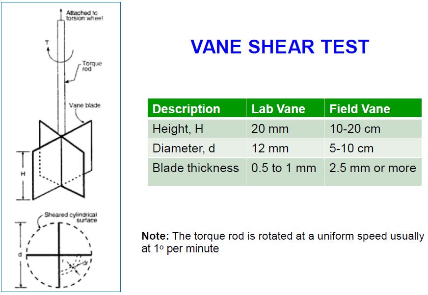
104 In-situ shear tests Vane shear test (suitable for soft to stiff clays) Torvane Pocket Penetrometer Pressuremeter Static Cone Penetrometer test (Push Cone Penetrometer Test, PCPT) Standard Penetration Test, SPT
105 Vane shear test This is one of the most versatile and widely used devices used for investigating undrained shear strength (C u ) and sensitivity of soft clays Applied Torque, T Bore hole (diameter = D B ) Disturbed soil Rupture surface h > 3D B ) Vane T H Vane PLAN VIEW D Rate of rotation : per minute Test can be conducted at 0.5 m vertical intervals
106 Vane shear test T = M s + M e + M e = M s + 2M e M e Assuming a uniform distribution of shear strength C u C u C u h Since the test is very fast, Unconsolidated Undrained (UU) can be expected d 2 M e (2rdr). C 0 M M e e u r d 2 2 2C u r dr 2 0 d/2 2C 3 u d 8 3 d/2 C u Cud 12 3 r 3 3 d 2 0
107 Vane shear test Since the test is very fast, Unconsolidated Undrained (UU) can be expected C u C u M s Shaft shear resistance along the circumference 2 2 d 2 h C d dhc M u u s d C h d C T u u d h d C T u d h d T C u T = M s + M e + M e = M s + 2M e
108 Vane shear test After the initial test, vane can be rapidly rotated through several revolutions until the clay become remoulded C u h peak ultimate C u Shear displacement Since the test is very fast, Unconsolidated Undrained (UU) can be expected Sensitivity Peak Stength Ultimate Stength


109 Some important facts on vane shear test Insertion of vane into soft clays and silts disrupts the natural soil structure around the vane causing reduction of shear strength The above reduction is partially regained after some time C u as determined by vane shear test may be a function of the rate of angular rotation of the vane
110 Correction for the strength parameters obtained from vane shear test Bjerrum (1974) has shown that as the plasticity of soils increases, C u obtained by vane shear tests may give unsafe results for foundation design. Therefore, he proposed the following correction. C u(design) = lc u(vane shear) Where, l = correction factor = log (PI) PI = Plasticity Index
111 In-situ shear tests Vane shear test Torvane (suitable for very soft to stiff clays) Pocket Penetrometer Pressuremeter Static Cone Penetrometer test (Push Cone Penetrometer Test, PCPT) Standard Penetration Test, SPT

112 Torvane Torvane is a modification to the vane
113 In-situ shear tests Vane shear test Torvane Pocket Penetrometer (suitable for very soft to stiff clays) Pressuremeter Static Cone Penetrometer test (Push Cone Penetrometer Test, PCPT) Standard Penetration Test, SPT
 is measured by a")
114 Pocket Penetrometer Pushed directly into the soil. The unconfined compression strength (q u ) is measured by a calibrated spring.
115 Various correlations for shear strength For NC clays, the undrained shear strength (c u ) increases with the effective overburden pressure, 0 c u ' ( PI) Skempton (1957) Plasticity Index as a % For OC clays, the following relationship is approximately true c u ' 0 Overconsolidated c u ' 0 Normally Consolidated (OCR) 0.8 Ladd (1977) For NC clays, the effective friction angle (f ) is related to PI as follows Sinf' log( IP) Kenny (1959)
116 Shear strength of partially saturated soils In the previous sections, we were discussing the shear strength of saturated soils. However, in most of the cases, we will encounter unsaturated soils in tropical countries like Sri Lanka Water Pore water pressure, u Air Water Pore air pressure, u a Pore water pressure, u w Solid Effective stress, Solid Effective stress, Saturated soils Unsaturated soils Pore water pressure can be negative in unsaturated soils
117 Shear strength of partially saturated soils Bishop (1959) proposed shear strength equation for unsaturated soils as follows f c' ( u ) ( u u ) tan ' n a a w f Where, n u a = Net normal stress u a u w = Matric suction = a parameter depending on the degree of saturation ( = 1 for fully saturated soils and 0 for dry soils) Fredlund et al (1978) modified the above relationship as follows f c' ( n u a ) tanf' ( u a u w b ) tanf Where, tanf b = Rate of increase of shear strength with matric suction
118 Shear strength of partially saturated soils f c' ( n u a ) tanf' ( u a u w ) b tanf Same as saturated soils Apparent cohesion due to matric suction Therefore, strength of unsaturated soils is much higher than the strength of saturated soils due to matric suction f - u a

119 How it become possible build a sand castle f c' ( n u a ) tanf' ( u a u w ) b tanf Same as saturated soils Apparent cohesion due to matric suction f Apparent cohesion - u a
120 Skempton s Pore Pressure Parameters During cell Pressure During shearing load Du c = B D 3 Du d = ABD d Total pore water pressure increment at any stage, Du Du = Du c + Du d Du = B [D 3 + AD d ] Du = B [D 3 + A(D 1 D 3 )] Skempton s water equation pore pressure

121 Skempton s Pore Pressure Parameters
122 Typical values for parameter B
123 Skempton s Pore Pressure Parameters
124 Skempton s Pore Pressure Parameters
125 Typical values for parameter A
126 Skempton s Pore Pressure Parameters -Example
127 Relation between effective and total stress criteria Three identical saturated soil samples are sheared to failure in UU triaxial tests. Each sample is subjected to a different cell pressure. No water can drain at any stage.
128 Relation between effective and total stress criteria Three identical saturated soil samples are sheared to failure in UU triaxial tests. Each sample is subjected to a different cell pressure. No water can drain at any stage. At failure the Mohr circles are found to be as shown 3 1
129 Relation between effective and total stress criteria Three identical saturated soil samples are sheared to failure in UU triaxial tests. Each sample is subjected to a different cell pressure. No water can drain at any stage. At failure the Mohr circles are found to be as shown 3 1 We find that all the total stress Mohr circles are the same size, and therefore f u = 0 and = s u = c u = constant
130 Relation between effective and total stress criteria Because each sample is at failure, the fundamental effective stress failure condition must also be satisfied. As all the circles have the same size there must be only one effective stress Mohr circle c' tan f' n
131 Relation between effective and total stress criteria Because each sample is at failure, the fundamental effective stress failure condition must also be satisfied. As all the circles have the same size there must be only one effective stress Mohr circle c' tan f' n We have the following relations c u = N + 2 c N 1 f 3 f
132 Relation between effective and total stress criteria The different total stress Mohr circles with a single effective stress Mohr circle indicate that the pore pressure is different for each sample. As discussed previously increasing the cell pressure without allowing drainage has the effect of increasing the pore pressure by the same amount (Du = D r ) with no change in effective stress. The change in pore pressure during shearing is a function of the initial effective stress and the moisture content. As these are identical for the three samples an identical strength is obtained.
133 Significance of undrained strength parameters It is often found that a series of undrained tests from a particular site give a value of f u that is not zero (c u not constant). If this happens either the samples are not saturated, or the samples have different moisture contents If the samples are not saturated, analyses based on undrained behaviour will not be correct The undrained strength c u is not a fundamental soil property. If the moisture content changes so will the undrained strength.
134 Example In an unconsolidated undrained triaxial test the undrained strength is measured as 17.5 kpa. Determine the cell pressure used in the test if the effective strength parameters are c = 0, f = 26 o and the pore pressure at failure is 43 kpa.
135 Example In an unconsolidated undrained triaxial test the undrained strength is measured as 17.5 kpa. Determine the cell pressure used in the test if the effective strength parameters are c = 0, f = 26 o and the pore pressure at failure is 43 kpa. Analytical solution Undrained strength = 17.5 = ( ) ( )
136 Example In an unconsolidated undrained triaxial test the undrained strength is measured as 17.5 kpa. Determine the cell pressure used in the test if the effective strength parameters are c = 0, f = 26 o and the pore pressure at failure is 43 kpa. Analytical solution Undrained strength = 17.5 = Failure criterion ( ) ( ) = N + 2 c N 1 f f
137 Example In an unconsolidated undrained triaxial test the undrained strength is measured as 17.5 kpa. Determine the cell pressure used in the test if the effective strength parameters are c = 0, f = 26 o and the pore pressure at failure is 43 kpa. Analytical solution Undrained strength = 17.5 = Failure criterion Hence 1 = 57.4 kpa, 3 = 22.4 kpa = N + 2 c N and cell pressure (total stress) = 3 + u = 65.4 kpa ( ) ( ) 1 f f
138 Graphical solution
139 Graphical solution
140 Graphical solution
141 Stress-Strain Behaviour of Soils
142 Stress-strain response of soils Triaxial tests are the standard means of investigating the stress-strain-strength response of soils. To simplify the presentation only simple shear tests will be considered.
143 Stress-strain response of soils Triaxial tests are the standard means of investigating the stress-strain-strength response of soils. To simplify the presentation only simple shear tests will be considered. The simple shear test is an improved shear box test which imposes more uniform stresses and strains.
144 Stress-strain response of soils Triaxial tests are the standard means of investigating the stress-strain-strength response of soils. To simplify the presentation only simple shear tests will be considered. The simple shear test is an improved shear box test which imposes more uniform stresses and strains. dx dz H g xz g xz = dx/h z = - dz/h = v
145 The Behaviour of Sands Depends on: Mean Effective stress (Normal effective stress in simple shear)
146 The Behaviour of Sands Depends on: Mean Effective stress (Normal effective stress in simple shear) Relative density, I d I d = e max - e e max - e min
147 The Behaviour of Sands Depends on: Mean Effective stress (Normal effective stress in simple shear) Relative density, I d I d = e max - e e max - e min g d = G s g w 1 + e
148 The Behaviour of Sands Depends on: Mean Effective stress (Normal effective stress in simple shear) Relative density, I d I d = e max - e e max - e min g d = G s g w 1 + e I d = 1 g 1 g dmin dmin g 1 g d dmax
149 The Behaviour of Sands Dense (D) Medium (M) Loose (L) e L g M v D D M g g L
150 The Behaviour of Sands For tests performed with the same normal stress All samples approach the same ultimate shear stress and void ratio, irrespective of the initial relative density Initially dense samples attain higher peak angles of friction Initially dense soils expand (dilate) when sheared Initially loose soils compress when sheared
151 The Behaviour of Sands e D 1 D 2 L L 1 g v D 1 D 2 D 1 D 2 g L 1 L 2 L 1 L 2 g
152 The Behaviour of Sands The ultimate values of shear stress and void ratio depend on the applied normal stress The ultimate stress ratio and angle of friction are independent of density and stress level Initially dense samples attain higher peak angles of friction, but the peak friction angle decreases as the stress increases Initially dense soils expand and initially loose soils compress when sheared. Increasing the normal stress causes less dilation (more compression)
153 Ultimate or Critical States All soil when sheared will eventually attain a unique stress ratio and reach a critical void ratio which is uniquely related to the normal stress.
154 Ultimate or Critical States All soil when sheared will eventually attain a unique stress ratio and reach a critical void ratio which is uniquely related to the normal stress. This ulimate state is called a Critical State A critical state is defined by d dg = d dg = d v dg = 0
155 Ultimate or Critical States All soil when sheared will eventually attain a unique stress ratio and reach a critical void ratio which is uniquely related to the normal stress. This ulimate state is called a Critical State A critical state is defined by d dg = d dg = d v dg = 0 In tests with different normal stresses different critical states will be reached.
156 Ultimate or Critical States All soil when sheared will eventually attain a unique stress ratio and reach a critical void ratio which is uniquely related to the normal stress. This ulimate state is called a Critical State A critical state is defined by d dg = d dg = d v dg = 0 In tests with different normal stresses different critical states will be reached. The locus of these critical states defines a line known as the Critical State Line (CSL)

157 The Critical State Line
158 Friction angles At critical states soil behaves as a purely frictional material f = f ult = f cs = constant f ult = F (mineralogy, grading, angularity) Typical values of f ult smectite clay 15 o clay 22 o sand 33 o angular gravel 40 o
159 Behaviour of clays Essentially the same as sands. However, data presented as a function of OCR rather than relative density. OCR is defined as OCR pc
160 Behaviour of clays Essentially the same as sands. However, data presented as a function of OCR rather than relative density. OCR is defined as e OCR pc swelling line NCL - normal consolidation line log
161 Behaviour of clays Essentially the same as sands. However, data presented as a function of OCR rather than relative density. OCR is defined as e OCR pc swelling line CSL NCL - normal consolidation line It is found that NCL and CSL have the same slope in e-log log

162 Behaviour of clays - drained response OCR = 1 OCR = 8 v OCR = 8 g NCL g OCR = 1
163 Behaviour of clays - drained response In drained loading the change in effective stress is identical to the change in total stress. In a shear box (or simple shear) test the normal stress is usually kept constant, and hence the response is fixed in the, plot. The soil heads towards a critical state when sheared, and this ultimate (or critical) state can be determined from the, plot. The change in void ratio can then be determined. Knowing the sign of the volume change enables the likely stressstrain response to be estimated.
164 Behaviour of clays - undrained response OCR = 1 OCR = 8 u +ve g OCR = 1 NCL g -ve OCR = 8
165 Behaviour of clays - undrained response In undrained loading the void ratio (moisture content) must stay constant. The soil must head towards a critical state when sheared, and knowing e the critical state can be determined from the e, plot. Once the critical state has been determined in the e, plot the ultimate shear stress is also fixed. The ultimate shear stress is related to the undrained strength. This relation can be obtained by considering a Mohr s circle.
166 Behaviour of clays - undrained response In undrained loading the void ratio (moisture content) must stay constant. The soil must head towards a critical state when sheared, and knowing e the critical state can be determined from the e, plot. Once the critical state has been determined in the e, plot the ultimate shear stress is also fixed. The ultimate shear stress is related to the undrained strength. This relation can be obtained by considering a Mohr s circle. s u ult cosf ult
167 Behaviour of clays - undrained response In undrained loading the effective stresses are fixed because void ratio (moisture content) must stay constant. The total stresses are controlled by the external loads, and the pore pressure is simply the difference between the total stress and effective stress. The CSL provides an explanation for the existence of cohesion (undrained strength) in frictional soils From the CSL it can also be seen that changes in moisture content (void ratio) will lead to different undrained strengths
168 Differences between sand and clay All soils are essentially frictional materials but different parameters are used for sands (I d ) and clays (OCR). Why?
169 Differences between sand and clay All soils are essentially frictional materials but different parameters are used for sands (I d ) and clays (OCR). Why? e Loose Dense Sand NCL log (MPa)
170 Differences between sand and clay All soils are essentially frictional materials but different parameters are used for sands (I d ) and clays (OCR). Why? e Clay Loose Sand Dense NCL NCL log (MPa)
Laboratory Testing Total & Effective Stress Analysis
 SKAA 1713 SOIL MECHANICS Laboratory Testing Total & Effective Stress Analysis Prepared by: Dr. Hetty Mohr Coulomb failure criterion with Mohr circle of stress 2 ' 2 ' ' ' 3 ' 1 ' 3 ' 1 Cot Sin c ' ' 2
Triaxial Shear Test. o The most reliable method now available for determination of shear strength parameters.
 TOPICS Introduction Components of Shear Strength of Soils Normal and Shear Stresses on a Plane Mohr-Coulomb Failure Criterion Laboratory Shear Strength Testing Direct Shear Test Triaxial Compression Test
Chapter (12) Instructor : Dr. Jehad Hamad
 Instructor : Dr. Jehad Hamad") Chapter (12) Instructor : Dr. Jehad Hamad 2017-2016 Chapter Outlines Shear strength in soils Direct shear test Unconfined Compression Test Tri-axial Test Shear Strength The strength of a material is the
Chapter (12) Instructor : Dr. Jehad Hamad 2017-2016 Chapter Outlines Shear strength in soils Direct shear test Unconfined Compression Test Tri-axial Test Shear Strength The strength of a material is the
Soil strength. the strength depends on the applied stress. water pressures are required
 Soil Strength Soil strength u Soils are essentially frictional materials the strength depends on the applied stress u Strength is controlled by effective stresses water pressures are required u Soil strength
SHEAR STRENGTH OF SOIL
 Soil Failure Criteria SHEAR STRENGTH OF SOIL Knowledge about the shear strength of soil important for the analysis of: Bearing capacity of foundations, Slope stability, Lateral pressure on retaining structures,
Chapter 5 Shear Strength of Soil
 Page 5 Chapter 5 Shear Strength of Soil. The internal resistance per unit area that the soil mass can offer to resist failure and sliding along any plane inside it is called (a) strength (b) shear strength
SHEAR STRENGTH OF SOIL
 SHEAR STRENGTH OF SOIL Necessity of studying Shear Strength of soils : Soil failure usually occurs in the form of shearing along internal surface within the soil. Shear Strength: Thus, structural strength
SOIL SHEAR STRENGTH. Prepared by: Dr. Hetty Muhammad Azril Fauziah Kassim Norafida
 SOIL SHEAR STRENGTH Prepared by: Dr. Hetty Muhammad Azril Fauziah Kassim Norafida What is shear strength Shear strength of a soil is the maximum internal resistance to applied shearing forces Why it is
Prof. B V S Viswanadham, Department of Civil Engineering, IIT Bombay
 56 Module 4: Lecture 7 on Stress-strain relationship and Shear strength of soils Contents Stress state, Mohr s circle analysis and Pole, Principal stressspace, Stress pathsin p-q space; Mohr-Coulomb failure
Shear Strength of Soil
 8 Shear Strength of Soil 8 1 INTRODUCTION As a structural member, a piece of steel is capable of resisting compression, tension, and shear. Soil, however, like concrete and rock, is not capable of resisting
Shear Strength of Soils
 Shear Strength of Soils STRESSES IN A SOIL ELEMENT t s v Analyze Effective Stresses (s ) Load carried by Soil t Where: s H t t s H s = t f = s v = s H = t = s v Stresses in a Soil Element after Figure
Theory of Shear Strength
 MAJ 1013 ADVANCED SOIL MECHANICS Theory of Shear Strength Prepared by, Dr. Hetty 1 Strength of different materials Steel Concrete Soil Tensile strength Compressive strength Shear strength Complex behavior
8.1. What is meant by the shear strength of soils? Solution 8.1 Shear strength of a soil is its internal resistance to shearing stresses.
 8.1. What is meant by the shear strength of soils? Solution 8.1 Shear strength of a soil is its internal resistance to shearing stresses. 8.2. Some soils show a peak shear strength. Why and what type(s)
D1. A normally consolidated clay has the following void ratio e versus effective stress σ relationship obtained in an oedometer test.
 (d) COMPRESSIBILITY AND CONSOLIDATION D1. A normally consolidated clay has the following void ratio e versus effective stress σ relationship obtained in an oedometer test. (a) Plot the e - σ curve. (b)
Theory of Shear Strength
 SKAA 1713 SOIL MECHANICS Theory of Shear Strength Prepared by, Dr. Hetty 1 SOIL STRENGTH DEFINITION Shear strength of a soil is the maximum internal resistance to applied shearing forces The maximum or
1.8 Unconfined Compression Test
 1-49 1.8 Unconfined Compression Test - It gives a quick and simple measurement of the undrained strength of cohesive, undisturbed soil specimens. 1) Testing method i) Trimming a sample. Length-diameter
Following are the results of four drained direct shear tests on an overconsolidated clay: Diameter of specimen 50 mm Height of specimen 25 mm
 444 Chapter : Shear Strength of Soil Example. Following are the results of four drained direct shear tests on an overconsolidated clay: Diameter of specimen 50 mm Height of specimen 5 mm Normal Shear force
Soil and Rock Strength. Chapter 8 Shear Strength. Steel Strength. Concrete Strength. Dr. Talat Bader May Steel. Concrete.
 Chapter 8 Shear Strength Dr. Talat Bader May 2006 Soil and Rock Strength Unconfined compressive strength (MPa) Steel Concrete 20 100 250 750 0.001 0.01 Soil 0.1 1.0 10 Rock 100 250 F y = 250 to 750 MPa
(Refer Slide Time: 02:18)
") Geology and Soil Mechanics Prof. P. Ghosh Department of Civil Engineering Indian Institute of Technology Kanpur Lecture 40 Shear Strength of Soil - C Keywords: Shear strength of soil, direct shear test,
Geology and Soil Mechanics Prof. P. Ghosh Department of Civil Engineering Indian Institute of Technology Kanpur Lecture 40 Shear Strength of Soil - C Keywords: Shear strength of soil, direct shear test,
SHEAR STRENGTH OF SOIL UNCONFINED COMPRESSION TEST
 SHEAR STRENGTH OF SOIL DEFINITION The shear strength of the soil mass is the internal resistance per unit area that the soil mass can offer to resist failure and sliding along any plane inside it. INTRODUCTION
SHEAR STRENGTH I YULVI ZAIKA
 SHEAR STRENGTH I YULVI ZAIKA MATERI Keruntuhan mohr coulomb, stress paths, kuat geser tanah non kohesif dan kohesif, evaluasi kuat geser di lapangan, tegangan normal dan tegangan geser pada sebuah bidang
Welcome back. So, in the last lecture we were seeing or we were discussing about the CU test. (Refer Slide Time: 00:22)
") Geology and Soil Mechanics Prof. P. Ghosh Department of Civil Engineering Indian Institute of Technology Kanpur Lecture - 43 Shear Strength of Soils Keywords: Triaxial shear test, unconsolidated undrained
Geology and Soil Mechanics Prof. P. Ghosh Department of Civil Engineering Indian Institute of Technology Kanpur Lecture - 43 Shear Strength of Soils Keywords: Triaxial shear test, unconsolidated undrained
Ch 4a Stress, Strain and Shearing
 Ch. 4a - Stress, Strain, Shearing Page 1 Ch 4a Stress, Strain and Shearing Reading Assignment Ch. 4a Lecture Notes Sections 4.1-4.3 (Salgado) Other Materials Handout 4 Homework Assignment 3 Problems 4-13,
Prof. B V S Viswanadham, Department of Civil Engineering, IIT Bombay
 51 Module 4: Lecture 2 on Stress-strain relationship and Shear strength of soils Contents Stress state, Mohr s circle analysis and Pole, Principal stressspace, Stress pathsin p-q space; Mohr-coulomb failure
Stress and Strains in Soil and Rock. Hsin-yu Shan Dept. of Civil Engineering National Chiao Tung University
 Stress and Strains in Soil and Rock Hsin-yu Shan Dept. of Civil Engineering National Chiao Tung University Stress and Strain ε 1 1 2 ε 2 ε Dimension 1 2 0 ε ε ε 0 1 2 ε 1 1 2 ε 2 ε Plane Strain = 0 1 2
Shear Strength of Soils
 ENVIRONMENTAL GEOTECHNICS Shear Strength of Soils Prof. Ing. Marco Favaretti University of Padova Department of Civil, Environmental and Architectural Engineering Via Ognissanti, 39 Padova (Italy) phone:
Table of Contents Chapter 1 Introduction to Geotechnical Engineering 1.1 Geotechnical Engineering 1.2 The Unique Nature of Soil and Rock Materials
 Table of Contents Chapter 1 Introduction to Geotechnical Engineering 1.1 Geotechnical Engineering 1.2 The Unique Nature of Soil and Rock Materials 1.3 Scope of This Book 1.4 Historical Development of Geotechnical
(Refer Slide Time 1:07 min)
") Soil Mechanics Prof. B.V.S. Viswanathan Department of Civil Engineering Indian Institute of Technology, Bombay Lecture 46 Shear Strength of Soils Lecture No.4 Students we had 3 lectures so far on this
Soil Mechanics Prof. B.V.S. Viswanathan Department of Civil Engineering Indian Institute of Technology, Bombay Lecture 46 Shear Strength of Soils Lecture No.4 Students we had 3 lectures so far on this
PRINCIPLES OF GEOTECHNICAL ENGINEERING
 PRINCIPLES OF GEOTECHNICAL ENGINEERING Fourth Edition BRAJA M. DAS California State University, Sacramento I(T)P Boston Albany Bonn Cincinnati London Madrid Melbourne Mexico City New York Paris San Francisco
FUNDAMENTALS SOIL MECHANICS. Isao Ishibashi Hemanta Hazarika. >C\ CRC Press J Taylor & Francis Group. Taylor & Francis Group, an Informa business
 SOIL MECHANICS FUNDAMENTALS Isao Ishibashi Hemanta Hazarika >C\ CRC Press J Taylor & Francis Group Boca Raton London New York CRC Press is an imprint of the Taylor & Francis Group, an Informa business
Calculation of 1-D Consolidation Settlement
 Calculation of 1-D Consolidation Settlement A general theory for consolidation, incorporating threedimensional flow is complicated and only applicable to a very limited range of problems in geotechnical
1.5 STRESS-PATH METHOD OF SETTLEMENT CALCULATION 1.5 STRESS-PATH METHOD OF SETTLEMENT CALCULATION
 Module 6 Lecture 40 Evaluation of Soil Settlement - 6 Topics 1.5 STRESS-PATH METHOD OF SETTLEMENT CALCULATION 1.5.1 Definition of Stress Path 1.5. Stress and Strain Path for Consolidated Undrained Undrained
2.7 Shear Strength of Unsaturated Soils
 2.7 Shear Strength of Unsaturated Soils D. G. FREDLUND, University of Saskatchewan, Saskatoon, Saskatchewan, Canada S. K. VANAPALLI, Lakehead University, Thunder Bay, Ontario, Canada 2.7.1 Introduction
7. STRESS ANALYSIS AND STRESS PATHS
 7-1 7. STRESS ANALYSIS AND STRESS PATHS 7.1 THE MOHR CIRCLE The discussions in Chapters and 5 were largely concerned with vertical stresses. A more detailed examination of soil behaviour requires a knowledge
INTERPRETATION OF UNDRAINED SHEAR STRENGTH OF UNSATURATED SOILS IN TERMS OF STRESS STATE VARIABLES
 INTERPRETATION OF UNDRAINED SHEAR STRENGTH OF UNSATURATED SOILS IN TERMS OF STRESS STATE VARIABLES S. K. Vanapalli and D.G. Fredlund Department of Civil Engineering University of Saskatchewan, Saskatoon
Lateral Earth Pressure
 1 of 11 6/2/2012 4:28 AM Lateral Earth Pressure The magnitude of lateral earth pressure depends on: 1. Shear strength characteristics of soil 2. Lateral strain condition 3. Pore water pressure 4. State
With high enough plate forces in opposite directions Bolts. How do these fail? Each pin has sheared into two pieces.
 SHEAR STRENGTH In general, the shear strength of any material is the load per unit area or pressure that it can withstand before undergoing shearing failure. Shearing When you Pins hear can Shear be used
Geotechnical Properties of Soil
 Geotechnical Properties of Soil 1 Soil Texture Particle size, shape and size distribution Coarse-textured (Gravel, Sand) Fine-textured (Silt, Clay) Visibility by the naked eye (0.05 mm is the approximate
INTRODUCTION TO STATIC ANALYSIS PDPI 2013
 INTRODUCTION TO STATIC ANALYSIS PDPI 2013 What is Pile Capacity? When we load a pile until IT Fails what is IT Strength Considerations Two Failure Modes 1. Pile structural failure controlled by allowable
Compressibility & Consolidation
 CHAPTER Compressibility & Consolidation Settlement If a structure is placed on soil surface, then the soil will undergo an elastic and plastic deformation. In engineering practice, the deformation or reduction
Introduction to Soil Mechanics
 Introduction to Soil Mechanics Sela Sode and Colin Jones WILEY Blackwell Contents Preface Dedication and Acknowledgments List of Symbols Soil Structure 1.1 Volume relationships 1.1.1 Voids ratio (e) 1.1.2
 QUESTION BANK DEPARTMENT: CIVIL SUBJECT CODE / Name: CE 2251 / SOIL MECHANICS SEMESTER: IV UNIT 1- INTRODUCTION PART - A (2 marks) 1. Distinguish between Residual and Transported soil. (AUC May/June 2012)
Soil Mechanics Prof. B.V.S. Viswanathan Department of Civil Engineering Indian Institute of Technology, Bombay Lecture 51 Earth Pressure Theories II
 Soil Mechanics Prof. B.V.S. Viswanathan Department of Civil Engineering Indian Institute of Technology, Bombay Lecture 51 Earth Pressure Theories II Welcome to lecture number two on earth pressure theories.
Shear strength. Common cases of shearing In practice, the state of stress in the ground will be complex. Common cases of shearing Strength
 Shear strength Common cases of shearing Strength Near any geotechnical construction (e.g. slopes, excavations, tunnels and foundations) there will be both mean and normal stresses and shear stresses. The
Class Principles of Foundation Engineering CEE430/530
 Class Principles of Foundation Engineering CEE430/530 1-1 General Information Lecturer: Scott A. Barnhill, P.E. Lecture Time: Thursday, 7:10 pm to 9:50 pm Classroom: Kaufmann, Room 224 Office Hour: I have
CONSOLIDATION OF SOIL
 Lecture-6 Soil consolidation Dr. Attaullah Shah 1 CONSOLIDATION OF SOIL When a soil mass is subjected to a compressive force there is a decrease in volume of soil mass. The reduction in volume of a saturated
Prof. B V S Viswanadham, Department of Civil Engineering, IIT Bombay
 50 Module 4: Lecture 1 on Stress-strain relationship and Shear strength of soils Contents Stress state, Mohr s circle analysis and Pole, Principal stressspace, Stress pathsin p-q space; Mohr-Coulomb failure
Compression and swelling. Mechanisms of compression. Mechanisms Common cases Isotropic One-dimensional Wet and dry states
 Compression and swelling Mechanisms Common cases Isotropic One-dimensional Wet and dry states The relationship between volume change and effective stress is called compression and swelling. (Consolidation
YOUR HW MUST BE STAPLED YOU MUST USE A PENCIL (no pens)
") Spring 2008 CIVE 462 HOMEWORK #1 1. Print out the syllabus. Read it. Write the grade percentages in the first page of your notes. 2. Go back to your 301 notes, internet, etc. and find the engineering definition
Spring 2008 CIVE 462 HOMEWORK #1 1. Print out the syllabus. Read it. Write the grade percentages in the first page of your notes. 2. Go back to your 301 notes, internet, etc. and find the engineering definition
Cavity Expansion Methods in Geomechanics
 Cavity Expansion Methods in Geomechanics by Hai-Sui Yu School of Civil Engineering, University of Nottingham, U. K. KLUWER ACADEMIC PUBLISHERS DORDRECHT / BOSTON / LONDON TABLE OF CONTENTS Foreword Preface
LATERAL EARTH PRESSURE
 . INTRODUCTION Retaining structures commonly used in foundation engineering, such as retaining walls, basement walls and bulkheads to support almost vertical slopes of earth masses. Proper design and construction
VALLIAMMAI ENGINEERING COLLEGE
 VALLIAMMAI ENGINEERING COLLEGE DEPARTMENT OF CIVIL ENGINEERING SUBJECT CODE : CE6405 YEAR : II SUBJECT NAME : SOIL MECHANICS SEM : IV QUESTION BANK (As per Anna University 2013 regulation) UNIT 1- SOIL
Advanced model for soft soils. Modified Cam-Clay (MCC)
") Advanced model for soft soils. Modified Cam-Clay (MCC) c ZACE Services Ltd August 2011 1 / 62 2 / 62 MCC: Yield surface F (σ,p c ) = q 2 + M 2 c r 2 (θ) p (p p c ) = 0 Compression meridian Θ = +π/6 -σ
Advanced model for soft soils. Modified Cam-Clay (MCC) c ZACE Services Ltd August 2011 1 / 62 2 / 62 MCC: Yield surface F (σ,p c ) = q 2 + M 2 c r 2 (θ) p (p p c ) = 0 Compression meridian Θ = +π/6 -σ
The process of consolidation and settlement
 Consolidation Based on part of the GeotechniCAL reference package by Prof. John Atkinson, City University, London The process of consolidation and settlement One-dimensional consolidation theory The oedometer
The CPT in unsaturated soils
 The CPT in unsaturated soils Associate Professor Adrian Russell (UNSW) Mr David Reid (Golder Associates) Prof Nasser Khalili (UNSW) Dr Mohammad Pournaghiazar (UNSW) Dr Hongwei Yang (Uni of Hong Kong) Outline
Landslide FE Stability Analysis
 Landslide FE Stability Analysis L. Kellezi Dept. of Geotechnical Engineering, GEO-Danish Geotechnical Institute, Denmark S. Allkja Altea & Geostudio 2000, Albania P. B. Hansen Dept. of Geotechnical Engineering,
Reinforced Soil Structures Reinforced Soil Walls. Prof K. Rajagopal Department of Civil Engineering IIT Madras, Chennai
 Geosynthetics and Reinforced Soil Structures Reinforced Soil Walls continued Prof K. Rajagopal Department of Civil Engineering IIT Madras, Chennai e-mail: gopalkr@iitm.ac.inac in Outline of the Lecture
pcf REQUIRED: Determine the shear strength parameters for use in a preliminary shallow foundation design. SOLUTION:
 14.330 SOIL MECHANICS Assignment #8: Shear Strength Solution. PROBLEM #1: GIVEN: A regional residential building contractor is planning on building a custom 4,100 ft² home on Martha s Vineyard, MA. The
EAA304/2 GEOTECHNICAL LABORATORY
 GEOTECHNICAL LABORATORY SCHOOL OF CIVIL ENGINEERING ENGINEERING CAMPUS UNIVERSITI SAINS MALAYSIA EAA304/2 GEOTECHNICAL LABORATORY No Laboratory Test G1 Direct Shear Test G2 Unconfined Compression Test
Soil Properties - I. Amit Prashant. Indian Institute of Technology Gandhinagar. Short Course on. Geotechnical Aspects of Earthquake Engineering
 Soil Properties - I Amit Prashant Indian Institute of Technology Gandhinagar Short Course on Geotechnical Aspects of Earthquake Engineering 04 08 March, 2013 Regional Soil Deposits of India Alluvial deposits
Tikrit University. College of Engineering Civil engineering Department CONSOILDATION. Soil Mechanics. 3 rd Class Lecture notes Up Copyrights 2016
 Tikrit University CONSOILDATION College of Engineering Civil engineering Department Soil Mechanics 3 rd Class Lecture notes Up Copyrights 2016 Stresses at a point in a soil mass are divided into two main
Appendix A Results of Triaxial and Consolidation Tests
 Appendix A Results of Triaxial and Consolidation Tests Triaxial and consolidation tests were performed on specimens of the soils used for interface testing. The objectives of these tests were as follows:
Soils. Technical English - I 10 th week
 Technical English - I 10 th week Soils Soil Mechanics is defined as the branch of engineering science which enables an engineer to know theoretically or experimentally the behavior of soil under the action
Module 5: Failure Criteria of Rock and Rock masses. Contents Hydrostatic compression Deviatoric compression
 FAILURE CRITERIA OF ROCK AND ROCK MASSES Contents 5.1 Failure in rocks 5.1.1 Hydrostatic compression 5.1.2 Deviatoric compression 5.1.3 Effect of confining pressure 5.2 Failure modes in rocks 5.3 Complete
Boreholes. Implementation. Boring. Boreholes may be excavated by one of these methods: 1. Auger Boring 2. Wash Boring 3.
 Implementation Boreholes 1. Auger Boring 2. Wash Boring 3. Rotary Drilling Boring Boreholes may be excavated by one of these methods: 4. Percussion Drilling The right choice of method depends on: Ground
Principles of Foundation Engineering 8th Edition Das SOLUTIONS MANUAL
 Principles of Foundation Engineering 8th Edition SOLUTIONS MANUAL Full clear download (no formatting errors) at: https://testbankreal.com/download/principles-foundation-engineering- 8th-edition-das-solutions-manual/
SHEAR STRENGTH OF SOIL. Chapter 10: Sections Chapter 12: All sections except
 SHEAR STRENGTH OF SOIL Chapter 10: Sections 10. 10.3 Chapter 1: All sections ecept 1.13 1.14 1.15 1.17 1.18 TOPICS Introduction Components of Shear Strength of Soils Normal and Shear Stresses on a Plane
SOIL MECHANICS: palgrave. Principles and Practice. Graham Barnes. macmiiian THIRD EDITION
 SOIL MECHANICS: Principles and Practice THIRD EDITION Graham Barnes palgrave macmiiian 'running Contents Preface xii Fine soil 19 List of symbols xiv Mass structure 21 Note on units xix Degree of weathering
2017 Soil Mechanics II and Exercises Final Exam. 2017/7/26 (Wed) 10:00-12:00 Kyotsu 4 Lecture room
 10:00-12:00 Kyotsu 4 Lecture room") 2017 Soil Mechanics II and Exercises Final Exam 2017/7/26 (Wed) 10:00-12:00 Kyotsu 4 Lecture room Attention: The exam consists of five questions for which you are provided with five answer sheets. Write
2017 Soil Mechanics II and Exercises Final Exam 2017/7/26 (Wed) 10:00-12:00 Kyotsu 4 Lecture room Attention: The exam consists of five questions for which you are provided with five answer sheets. Write
Interpretation of Flow Parameters from In-Situ Tests (P.W. Mayne, November 2001)
") Interpretation of Flow Parameters from In-Situ Tests (P.W. Mayne, November 2001) FLOW PROPERTIES Soils exhibit flow properties that control hydraulic conductivity (k), rates of consolidation, construction
Interpretation of Flow Parameters from In-Situ Tests (P.W. Mayne, November 2001) FLOW PROPERTIES Soils exhibit flow properties that control hydraulic conductivity (k), rates of consolidation, construction
Table 3. Empirical Coefficients for BS 8002 equation. A (degrees) Rounded Sub-angular. 2 Angular. B (degrees) Uniform Moderate grading.
 Rounded Sub-angular. 2 Angular. B (degrees) Uniform Moderate grading.") Hatanaka and Uchida (1996); ' 20N 20 12N 20 ' 45 A lower bound for the above equation is given as; 12N 15 ' 45 Table 3. Empirical Coefficients for BS 8002 equation A Angularity 1) A (degrees) Rounded 0
Hatanaka and Uchida (1996); ' 20N 20 12N 20 ' 45 A lower bound for the above equation is given as; 12N 15 ' 45 Table 3. Empirical Coefficients for BS 8002 equation A Angularity 1) A (degrees) Rounded 0
Chapter (5) Allowable Bearing Capacity and Settlement
 Allowable Bearing Capacity and Settlement") Chapter (5) Allowable Bearing Capacity and Settlement Introduction As we discussed previously in Chapter 3, foundations should be designed for both shear failure and allowable settlement. So the allowable
Chapter (5) Allowable Bearing Capacity and Settlement Introduction As we discussed previously in Chapter 3, foundations should be designed for both shear failure and allowable settlement. So the allowable
Adapting The Modified Cam Clay Constitutive Model To The Computational Analysis Of Dense Granular Soils
 University of Central Florida Electronic Theses and Dissertations Masters Thesis (Open Access) Adapting The Modified Cam Clay Constitutive Model To The Computational Analysis Of Dense Granular Soils 2005
23/04/2016. Centrifuge Tests. Coulomb s (1773) design strength. = c + tan d
 design strength. = c + tan d") 1 2 "Critical States of Soil and Geotechnical Centrifuge Tests Coulomb s (1773) design strength = c + tan d (2) Geotechnical Society 2016 Andrew N. Schofield, Cambridge University Engineering Department
1 2 "Critical States of Soil and Geotechnical Centrifuge Tests Coulomb s (1773) design strength = c + tan d (2) Geotechnical Society 2016 Andrew N. Schofield, Cambridge University Engineering Department
LABORATORY MEASUREMENTS OF STIFFNESS OF SOFT CLAY USING BENDER ELEMENTS
 LABORATORY MEASUREMENTS OF STIFFNESS OF SOFT CLAY USING BENDER ELEMENTS ABSTRACT: S. H. Oh 1, D. S. Park 2, B. J. Kim 3, E. J. Kim 1 and Y. J. Mok 4 1 Research Assistant, Dept. of Civil Eng., Kyunghee
GEOTECHNICAL PARAMETERS OBTAINED WITH NONLINEAR COMPUTATIONAL MODELS USED IN GEOTECHNICAL ENGINEERING PROBLEMS
 INTERNATIONAL SCIENTIFIC CONFERENCE CIBv 2010 12 13 November 2010, Braşov GEOTECHNICAL PARAMETERS OBTAINED WITH NONLINEAR COMPUTATIONAL MODELS USED IN GEOTECHNICAL ENGINEERING PROBLEMS Iulia-Consuela MOLNAR*,
Principal Symbols. f. Skin friction G Shear modulus. Cu Coefficient of uniformity Cc Coefficient of curvature
 Principal Symbols A, a Area A Air content A, A Pore pre.ssure coefficients a' Modified shear strength parameter (effective stress) a Dial gauge reading in oedometer test B Width of footing B, B Pore pressure
Shear Strength of Soil. Hsin-yu Shan Dept. of Civil Engineering National Chiao Tung University
 Shear Strength o Soil Hsin-yu Shan Dept. o Civil Engineering National Chiao Tung University Normally Consolidated Clays s u ( ) = 2 1 z c p = s u c 1 is the index o mobilization o shear strength The shear
both an analytical approach and the pole method, determine: (a) the direction of the
 the direction of the") Quantitative Problems Problem 4-3 Figure 4-45 shows the state of stress at a point within a soil deposit. Using both an analytical approach and the pole method, determine: (a) the direction of the principal
Quantitative Problems Problem 4-3 Figure 4-45 shows the state of stress at a point within a soil deposit. Using both an analytical approach and the pole method, determine: (a) the direction of the principal
CPT Applications - Liquefaction 2
 CPT Applications - Liquefaction 2 Peter K. Robertson CPT in Geotechnical Practice Santiago, Chile July, 2014 Definitions of Liquefaction Cyclic (seismic) Liquefaction Zero effective stress (during cyclic
Chapter 2. 53% v. 2.2 a. From Eqs. (2.11) and (2.12), it can be seen that, 2.67
 and (2.12), it can be seen that, 2.67") Chapter 2 2.1 d. (87.5)(9.81) (1000)(0.05) 3 17.17 kn/m c. d 1 w 17.17 1 0.15 3 14.93 kn/m G a. Eq. (2.12): s w (2.68)(9.81). 14.93 ; e 0.76 1 e 1 e e 0.76 b. Eq. (2.6): n 0.43 1 e 1 0.76 Vw wgs (0.15)(2.68)
Chapter 2 2.1 d. (87.5)(9.81) (1000)(0.05) 3 17.17 kn/m c. d 1 w 17.17 1 0.15 3 14.93 kn/m G a. Eq. (2.12): s w (2.68)(9.81). 14.93 ; e 0.76 1 e 1 e e 0.76 b. Eq. (2.6): n 0.43 1 e 1 0.76 Vw wgs (0.15)(2.68)
NEW DOWN-HOLE PENETROMETER (DHP-CIGMAT) FOR CONSTRUCTION APPLICATIONS
 FOR CONSTRUCTION APPLICATIONS") NEW DOWN-HOLE PENETROMETER (DHP-CIGMAT) FOR CONSTRUCTION APPLICATIONS 1 2 C. Vipulanandan 1, Ph.D., M. ASCE and Omer F. Usluogullari 2 Chairman, Professor, Director of Center for Innovative Grouting Materials
NEW DOWN-HOLE PENETROMETER (DHP-CIGMAT) FOR CONSTRUCTION APPLICATIONS 1 2 C. Vipulanandan 1, Ph.D., M. ASCE and Omer F. Usluogullari 2 Chairman, Professor, Director of Center for Innovative Grouting Materials
A Constitutive Framework for the Numerical Analysis of Organic Soils and Directionally Dependent Materials
 Dublin, October 2010 A Constitutive Framework for the Numerical Analysis of Organic Soils and Directionally Dependent Materials FracMan Technology Group Dr Mark Cottrell Presentation Outline Some Physical
Module 4 Lecture 20 Pore water pressure and shear strength - 4 Topics
 Module 4 Lecture 20 Pore water pressure and shear strength - 4 Topics 1.2.6 Curvature of the Failure Envelope Effect of angularity of soil particles Effect of rate of loading during the test 1.2.7 Shear
Modified Cam-clay triaxial test simulations
 1 Introduction Modified Cam-clay triaxial test simulations This example simulates a series of triaxial tests which can be used to verify that Modified Cam-Clay constitutive model is functioning properly.
8. STRENGTH OF SOILS AND ROCKS
 8-1 8. STRENGTH OF SOILS AND ROCKS 8.1 COMPRESSIVE STRENGTH The strength of a material may be broadly defined as the ability of the material to resist imposed forces. If is often measured as the maximum
Cyclic Behavior of Sand and Cyclic Triaxial Tests. Hsin-yu Shan Dept. of Civil Engineering National Chiao Tung University
 Cyclic Behavior of Sand and Cyclic Triaxial Tests Hsin-yu Shan Dept. of Civil Engineering National Chiao Tung University Causes of Pore Pressure Buildup due to Cyclic Stress Application Stress are due
Evaluation of soil liquefaction using the CPT Part 2
 Evaluation of soil liquefaction using the CPT Part 2 P.K. Robertson 2013 Definitions of Liquefaction Cyclic (seismic) Liquefaction Zero effective stress (during cyclic loading) Flow (static) Liquefaction
Axially Loaded Piles
 Axially Loaded Piles 1 t- Curve Method using Finite Element Analysis The stress-strain relationship for an axially loaded pile can be described through three loading mechanisms: axial deformation in the
SOIL MODELS: SAFETY FACTORS AND SETTLEMENTS
 PERIODICA POLYTECHNICA SER. CIV. ENG. VOL. 48, NO. 1 2, PP. 53 63 (2004) SOIL MODELS: SAFETY FACTORS AND SETTLEMENTS Gabriella VARGA and Zoltán CZAP Geotechnical Department Budapest University of Technology
Cyclic Triaxial Behavior of an Unsaturated Silty Soil Subjected to Suction Changes
 6 th International Conference on Earthquake Geotechnical Engineering 1-4 November 215 Christchurch, New Zealand Cyclic Triaxial Behavior of an Unsaturated Silty Soil Subjected to Suction Changes T. Nishimura
The Bearing Capacity of Soils. Dr Omar Al Hattamleh
 The Bearing Capacity of Soils Dr Omar Al Hattamleh Example of Bearing Capacity Failure Omar Play the move of bearing Capacity failure The Philippine one Transcona Grain Silos Failure - Canada The Bearing
Soil Mechanics Brief Review. Presented by: Gary L. Seider, P.E.
 Soil Mechanics Brief Review Presented by: Gary L. Seider, P.E. 1 BASIC ROCK TYPES Igneous Rock (e.g. granite, basalt) Rock formed in place by cooling from magma Generally very stiff/strong and often abrasive
TIME-DEPENDENT BEHAVIOR OF PILE UNDER LATERAL LOAD USING THE BOUNDING SURFACE MODEL
 TIME-DEPENDENT BEHAVIOR OF PILE UNDER LATERAL LOAD USING THE BOUNDING SURFACE MODEL Qassun S. Mohammed Shafiqu and Maarib M. Ahmed Al-Sammaraey Department of Civil Engineering, Nahrain University, Iraq
Chapter 12 Subsurface Exploration
 Page 12 1 Chapter 12 Subsurface Exploration 1. The process of identifying the layers of deposits that underlie a proposed structure and their physical characteristics is generally referred to as (a) subsurface
Ch 5 Strength and Stiffness of Sands
 Ch. 5 - Strength and Stiffness of Sand Page 1 Ch 5 Strength and Stiffness of Sands Reading Assignment Ch. 5 Lecture Notes Sections 5.1-5.7 (Salgado) Other Materials Homework Assignment Problems 5-9, 5-12,
APPLICATION OF THE EXPERIMENTAL TESTS OF THE SHEAR STRENGTH OF SOILS IN THE GEOTECHNICAL DESIGN. 1. Introduction
 ROCZNIKI INŻYNIERII BUDOWLANEJ ZESZYT 14/014 Komisja Inżynierii Budowlanej Oddział Polskiej Akademii Nauk w Katowicach APPLICATION OF THE EXPERIMENTAL TESTS OF THE SHEAR STRENGTH OF SOILS IN THE GEOTECHNICAL
Earth Pressure Theory
 Lateral Earth Pressure Page 1 Earth Pressure Theory Examples of Retaining Walls Lateral Earth Pressure Page 2 At-Rest, Active and Passive Earth Pressure Wednesday, August 17, 2011 12:45 PM At-rest condition
(Refer Slide Time: 01:15)
") Soil Mechanics Prof. B.V.S. Viswanathan Department of Civil Engineering Indian Institute of Technology, Bombay Lecture 56 Stability analysis of slopes II Welcome to lecture two on stability analysis of
Soil Mechanics Prof. B.V.S. Viswanathan Department of Civil Engineering Indian Institute of Technology, Bombay Lecture 56 Stability analysis of slopes II Welcome to lecture two on stability analysis of
(C) Global Journal of Engineering Science and Research Management
 Global Journal of Engineering Science and Research Management") GEOTECHNCIAL ASSESSMENT OF PART OF PORT HARCOURT, NIGER DELTA FOR STRUCTURAL ANALYSIS Warmate Tamunonengiyeofori Geostrat International Services Limited, www.geostratinternational.com. *Correspondence
GEOTECHNCIAL ASSESSMENT OF PART OF PORT HARCOURT, NIGER DELTA FOR STRUCTURAL ANALYSIS Warmate Tamunonengiyeofori Geostrat International Services Limited, www.geostratinternational.com. *Correspondence