TIME-DEPENDENT BEHAVIOR OF PILE UNDER LATERAL LOAD USING THE BOUNDING SURFACE MODEL
|
|
|
- Jeffery Gilmore
- 5 years ago
- Views:
Transcription
1 TIME-DEPENDENT BEHAVIOR OF PILE UNDER LATERAL LOAD USING THE BOUNDING SURFACE MODEL Qassun S. Mohammed Shafiqu and Maarib M. Ahmed Al-Sammaraey Department of Civil Engineering, Nahrain University, Iraq ABSTRACT Time-dependent behavior of pile embedded in saturated porous medium has been investigated in this study using the finite element method. This behavior occurs due to consolidation of the saturated medium which was implemented through a fully coupled Biot formulation. The finite element analyses were carried out using the elasto-plastic bounding surface model for representing soil surrounding the pile. The model together with Biot consolidation were implemented and verified. The investigation of the time-dependent behavior of pile under lateral load was then carried out in five types of cohesive soils and the results showed that the elasto-plastic bounding surface model provide a realistic stress distribution within the soil mass around the pile. Also, it was observed that significant influence of time (i.e., consolidation process) on pile displacements will appeared. Finally, the study shows a significant influence of the critical state parameters λ and κ on the time-dependent behavior of pile under lateral load. Keywords: pile, finite element, bounding surface model, consolidation, lateral response. INTRODUCTION Pile foundations are usually used when heavy structural loads have to be transmitted through weaker subsoil. When used under tall chimneys, high rise structures and coastal and offshore structures, piles are also subjected to significant amounts of lateral loads and overturning moments besides axial loads. Thus proper attention has to be given in designing such pile-supported structures under lateral loads. In very soft clayed ground, however, even if the bearing capacity of a pile foundation is sufficient enough to resist vertical load, the long-term settlement of the pile foundation due to vertical static load cannot be neglected. Sometimes this causes big problems, especially in those structures like railway bridges whose deformation is strictly restricted. For performance based design, it is necessary to check the vertical displacement not only in short-term, but also in long-term. Many prediction methods can be found in literature for the settlement in soft ground. But for pile foundation, due to the difficulty in evaluating the interaction of pile-soil-pile system, quantitative prediction method for long-term settlement in soft ground is still need to be developed. With the development of the finite element method, the ability to numerically model complicated soil structure has become possible. Geotechnical construction is one such area that has been investigated extensively by the finite element method. The work presented in this study is concerned with one particular area of geotechnical construction, that of piles. However, to be successfully used in practical design, the soil model should be able to represent the soil behavior as close to reality and can be calibrated by conventional field or lab testing. On the other hand, the model should be able to realistically capture the most important aspects of soil-structure nonlinearities. In view of this, the present paper focuses on the study of time-dependent behavior of piles in saturated cohesive soils subjected to lateral loads through 2D finiteelement analyses. BOUNDING SURFACE MODEL FOR SOIL The numerical implementation of the model and the parameters associated with the model are available in Dafalias and Herrmann, (1986) and Herrmann et al., (1987). The elasto-plastic rate relations are the total strain rate is consisting of two parts: elastic strain and plastic strain. where a dot indicates a rate and an associated flow rule is assumed. The inverse form of the constitutive relations is obtained as: where (1) (2) (3) (4a) 1070
2 (4b) and where K and G represent the elastic bulk and shear moduli, respectively; is the Kronecker delta; the plastic modulus; I, J and α are the stress invariants; 1 b and F represents the analytical expression of the bounding surface; represents the deviatoric part of the stress tensor and represents the third deviatoric stress invariant. FORMS OF THE BOUNDING SURFACE The analytical definition of the bounding surface may assume many particular forms provided it satisfies certain requirements concerning the shape of the surface (Dafalias and Herrmann, 1986). The analytical expressions for a composite form of the bounding surface, consisting of two ellipses and one hyperbola, with continuous tangents at their connecting points (Figure-1), are presented below (Dafalias and Herrmann, 1986). For ellipse 1: For the hyperbola: (5) (6) determine the ratio of the major to minor axis of ellipse 1 (2.0 R 3.0). A (α) = parameter defines the distance D = AI of apex H of the hyperbola from its center G intersection of the two asymptotes and thus pertains only to the composite form of the surface, Ac = A in compression, Ae = A in extension, shape parameter controls the shape of the hyperbolic portion of the bounding surface (0.02 A 0.2). T = It /I parameter which determines the purely tensile strength of the material, and T also pertains to the composite form of the surface, C = 0 C <1 parameter which determines the center of the bounding surface Ic = CI. The projection center parameter (0 C 1) defines the point along the I-axis which serves as the projection center in the radial mapping rule. Hardening parameters s p = parameter which determines indirectly elastic nucleus. For s p = 1 the elastic nucleus degenerates to point Ic center of bounding surface and as s p the elastic nucleus expands towards the bounding surface. h = slope-hardening factor, which is a function of lode angle (α), hc = for compression (hc = h (π/6)), he = for extension (he = h ( π/6)) a and w = hardening parameters if the single ellipse version of the bounding surface is used. m = a positive model parameter. For ellipse 2: (7a) where: (7b), (7c) ELASTO-PLASTIC BOUNDING SURFACE MODEL PARAMETERS The parameters are divided into the following three groups (Kaliakin, 2005): Traditional material constants λ = slope of consolidation line κ = slope of swelling line N (α) = slope of critical state line, Nc = N in compression Ne =N in extension υ= Poisson s ratio Surface configuration parameters R(α) = R > 1defines the point I1 =I /R (Figure-1), which together with point J1 defines the coordinates of point H which is the intersection of F = 0 and CSL, Rc = R in compression, Re = R in extension, shape parameter Figure-1. Bounding surface in stress invariants space (after Dafalias and Herrmann, 1986). FINITE ELEMENT FORMULATION The elasto-plastic bounding surface model described above is incorporated in a finite element program, which has the feature of modeling twodimensional (plane strain and axisymmetric) geotechnical problems such as consolidation, written by FORTRAN90 language. This program is primarily based on the programs presented by Smith and Griffiths (2004) for the analysis of two-dimensional solid by finite element method utilizing elastic constitutive relationship and which is modified for the purpose of this study. So in addition to the elasto-plastic bounding surface model, the 1071
3 program allows one to assign linear elastic behavior to any part of the problem geometry together with Mohr- Coulomb model for representing cohesionless soil. Description of all of the program features is beyond the scope of this paper, and a brief summary of the feature relevant to this study is given below. Transient formulation In the case of a pile in saturated porous medium, the loading is time-dependent, so an incremental formulation was used in the following work producing the matrix version of the Biot equation at the element level presented below (Lewis and Schrefler, 1987). K L L u k K u df/dt + C k T = T + S+ αh t p L S ( 1 α) H t p F (8) L where: K = element solid stiffness matrix, L = element coupling matrix, H = element fluid stiffness matrix, u = change in nodal displacements, p = change in nodal excess pore-pressures, S = the compressibility matrix, F = load vector, t = calculation time step, α = time stepping parameter (=1 in this work), df / dt = change in nodal forces. TIME-DEPENDENT BEHAVIOR OF PILE IN SEVERAL TYPES OF COHESIVE SOIL UNDER LATERAL LOADING A time-dependent behavior of a pile with diameter Dp = 1m and length of 10m which can be considered to be short pile embedded in a layer of saturated elasto-plastic cohesive soil which obeys the bounding surface model is studied. This problem was previously investigated by Carter and Taibat (2001) but the pile was embedded in a layer of saturated cohesionless soil which obeys the Mohr-Coulomb failure criterion where the friction angle of the soil is assumed to be φ = 30 and the soil is also assumed to have a submerged unit weight of γ sub = 0.7 γ w, where γ w is the unit weight of pore water, a Young's modulus for fully drained conditions given by E's = 3000 γ w and a Poisson's ratio v' = The predicted load-displacement curves for the pile head, for cases where the pile deforms under undrained and drained conditions are presented in Figures (3) and (4), respectively. The figures show good comparisons between the results of the program modified for the purpose of this study and those obtained by Carter and Taibat (2001). In this study five types of cohesive soils are considered in the analysis, which are Kaolin mix soil (K2- soil), Kaolin soil (K1-soil), Marine silty soil (M-soil), Grenoble soil (G-soil) and Umeda soil (U-soil); the parameters of these soils are presented in Table-1 (Kaliakin and Dafalias, 1991), where the parameters sp, a and w are fixed for all type of soils as 1, 1.2 and 5 respectively. The pile is subjected to a lateral loading applied at the midline. The problem is analyzed assuming elastic model for pile material with parameters given in Table-2, and elasto-plastic bounding surface model for soil surrounding the pile. The finite element mesh and dimensions of the problem are shown in Figure-2. All elasto-plastic analyses have been carried out using 8-nodes quadrilateral finite element. In order to examine the time dependent consolidation behavior of the pile, it is convenient to introduce a non-dimensional time factor T v, defined as: Where k is the coefficient of soil permeability and t represents time. (9) Table-1. Bounding surface parameters for the five cohesive soils (after Kaliakin and Dafalias, 1991). Properties soil type λ κ ν M c M e R c R e A c A e C h c h e Kaolin mix Kaolin a Marine silty a 0.1 a Grenoble Umeda a 0.01 a a a Material response in extension was not simulated Table-2. Properties for pile material (after Carter and Taibat, 2001). Properties Values γ c, unit weight, kn/m Poisson s ratio 0.2 E p, modulus of elasticity, kn/m 2 30*

.")
 on the displacements.")
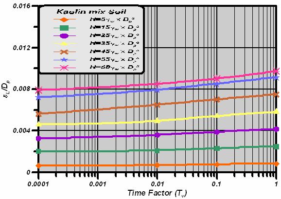
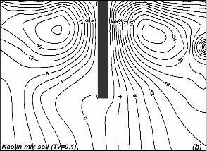
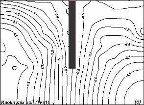
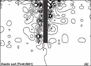
4 Figure-2. Finite element mesh. Figure-3. Comparison of the pile response with different soil models, each deforming under undrained conditions. Figure-4. Comparison of the pile response with different soil models, each deforming under fully drained conditions. In the elasto-plastic analysis, the lateral pile displacements developed depending on lateral loads H = 5γ w D p 3, H = 35γ w D p 3 and H = 60γ w D p 3 and time factors T v = , 0.1 and 1.0 along depth of pile embedded in K2-soil, K1-soil, M-soil, G-soil and U-soil are shown in Figures (5a, 5b, 5c, 5d and 5e, respectively). It can be observed that the maximum displacement appeared at the head of pile decreasing with the depth and the lower lateral loading the lower are the lateral displacements along the depth of pile, also there appear to be significant influence of time (i.e., consolidation process) on the displacements. The influence become more clearly with increasing the lateral loading that higher displacements were observed with time due to consolidation process, and this appear obviously in Figures (6a, 6b, 6c, 6d and 6e) which draws the lateral time-dependent displacements of pile head under lateral loadings H= 5, 15, 25, 35, 45, 55 and 60(γ w D p 3 ) in all soils. Also from these Figures a reduction in displacements by about 90% and 40% are observed if about 10% and 60% of maximum lateral load is applied, respectively. And it can be indicated that the displacement of pile head in all cohesive soils under all loadings will increased during consolidation process by about 23% to 53% of that at the beginning time of consolidation (i.e., T v = ) due to dissipation of excess pore water pressure according to the manner discussed below, which causes higher effective stress and thus higher displacements. The enlargement of displacement will be in a decreasing rate ranging between about 14% to 35% at earlier stage of consolidation process from time factor T v = to 0.01 being between 7% to 18% at the later stage of consolidation from T v = 0.01 to 1.0. The excess pore water pressure (EPWP in kpa) contours at lateral load of H = 60γ w D p 3 with time factors T v = , 0.1 and 1.0 for K2-soil are shown in Figures (7a, 7b and 7c), for K1-soil in Figures (8a, 8b and 8c), for M-soil in Figures (9a, 9b and 9c), for G-soil in Figures (10a, 10b and 10c) and for U-soil in Figures (11a, 11b and 11c). In these figures it should be observed that all of pore pressures are positive in front of pile with the direction of loading reflecting the compression due to lateral loading on pile head and negative at back side of pile due to unloading and they are concentrated near the upper part of pile. And it can be noticed that the EPWP distribution is irregular at the beginning time of consolidation T v = became more regular with time, also the long term dissipation will be in higher rate near the head of the pile. At time factor T v =1.0 the EPWP values near head of pile will be lower than that near the base being increased away from piles and remains zero below it. With regard to the influence of bounding surface parameters on the lateral displacement of pile under lateral loading and from Figure-12 which plot the largest lateral displacements of pile with depth for the five types of cohesive soils under the higher lateral loading H = 60γ w D p 3 and time factor T v = 1.0 it can be concluded that the lateral displacement increase with increasing the values of the model parameters λ and ν that for cohesive soils that have higher values of the parameters λ and ν and lower values of M, ν, R, h, A, and C larger displacements were noticed especially at the pile head. Also lower rate of increasing the displacements with time were noticed for K2-soil which have smaller values of the parameters λ 1073

.")
. Figure-5(a). (K2-soil).")
. Figure-6(a).")
. Figure-5(c).")
5 and κ and larger values for other parameters being higher in the soils with larger values of λ and κ parameters and lower values for the others. Figure-5(d). Lateral displacement of pile with depth (G-soil). Figure-5(a). Lateral displacement of pile with depth (K2-soil). Figure-5(e). Lateral displacement of pile with depth (U-soil). Figure-5(b). Lateral displacement of pile with depth (K1-soil). Figure-6(a). The time-dependent lateral displacements of the pile head (K2-soil). Figure-5(c). Lateral displacement of pile with depth (M-soil). 1074

. Figure-6(d).")
. Figure-6(e).")


6 Figure-6(b). The time-dependent lateral displacements of the pile head (K1-soil). Figure-6(d). The time-dependent lateral displacements of the pile head (G-soil). Figure-6(c). The time-dependent lateral displacements of the pile head (M-soil). Figure-6(e). The time-dependent lateral displacements of the pile head (U-soil). Figure-7. EPWP for pile under lateral loading in K2-soil. Figure-8. EPWP for pile under lateral loading in K1-soil. 1075


.")


7 Figure-9. EPWP for pile under lateral loading in M-soil. Figure-10. EPWP for pile under lateral loading in G-soil. Figure-11. EPWP for pile under lateral loading in U-soil. soils are modeled via bounding surface type plasticity, which allows the plastic displacement to occur for stress points within the surface. A parametric study is carried out to address the influence of various factors, such as load intensity, consolidation process and bounding surface parameters on the prediction of time-dependent piled foundation behavior in several types of cohesive soils and the following conclusions can be drawn: Figure-12. Lateral displacement of pile with depth (All Soils). CONCLUSIONS A finite element analysis of the time-dependent behavior of pile in saturated cohesive soils subjected to lateral loadings. The nonlinear stress-strain behaviors of For pile subjected to lateral load the long term lateral displacement of pile head in all cohesive soils under all loadings may reach to about 50% of that from short term due to dissipation of excess pore water pressure. There appear to be significant influence of time (i.e., consolidation process) on the displacements, thus for piles in saturated clays it is highly recommended to take such influence in to consideration by the designer. For cohesive soils that have higher values of the bounding surface model parameters λ and κ and lower values of M, ν, R, h, A, and C, lower excess pore 1076
8 pressure contours exist. This causes higher effective stress and thus higher lateral displacements. The EPWP distribution is irregular at the beginning time of consolidation became more regular with time; also the long term dissipation will be in higher rate near the head of the pile. With time the EPWP values near head of pile will be lower than that near the base being increased away from piles and remains zero below it. REFERENCES Dafalias Y. F. and Herrmann L. R Bounding Surface Plasticity II: Application to Isotropic Cohesive Soils. Journal of Engineering Mechanics, ASCE. 112(12): Herrmann L. R., Kaliakin V. N., Shen C. K., Mish K. D. and Zhu Z Numerical Implementation of Plasticity Model for Cohesive Soils. Journal of Engineering Mechanics. 113(4): Kaliakin V. N. and Dafalias Y. F Details Regarding the Cohesive Soils. Civil Engineering Report No.91-1, University of Delaware, Newark. Kaliakin V.N Parameter Estimation for Time- Dependent Bounding Surface Models. Geo-Frontiers Conference; Soil Constitutive Models: Evaluation, Selection, and Calibration. Geotechnical special publication. (128): Lewis R. W. and Schrefler B. A The Finite Element Method in the Deformation and Consolidation of Porous Media. John Wiley and Sons, Ltd., London, U.K. Smith I. M. and Griffiths D. V Programming Finite Element Method. 4 th Ed. John Wiley and Sons. Carter J.P. and Taiebat H.T A semi-analytical finite element method for three dimensional consolidation analysis. Civil Engineering Department, the University of Sydney, Sydney, NSW 2006, Australia, Computers and Geotechnics. pp
CONSOLIDATION BEHAVIOR OF PILES UNDER PURE LATERAL LOADINGS
 VOL., NO., DECEMBER 8 ISSN 89-8 -8 Asian Research Publishing Network (ARPN). All rights reserved. CONSOLIDATION BEAVIOR OF PILES UNDER PURE LATERAL LOADINGS Qassun S. Mohammed Shafiqu Department of Civil
Advanced model for soft soils. Modified Cam-Clay (MCC)
") Advanced model for soft soils. Modified Cam-Clay (MCC) c ZACE Services Ltd August 2011 1 / 62 2 / 62 MCC: Yield surface F (σ,p c ) = q 2 + M 2 c r 2 (θ) p (p p c ) = 0 Compression meridian Θ = +π/6 -σ
Advanced model for soft soils. Modified Cam-Clay (MCC) c ZACE Services Ltd August 2011 1 / 62 2 / 62 MCC: Yield surface F (σ,p c ) = q 2 + M 2 c r 2 (θ) p (p p c ) = 0 Compression meridian Θ = +π/6 -σ
SOIL MODELS: SAFETY FACTORS AND SETTLEMENTS
 PERIODICA POLYTECHNICA SER. CIV. ENG. VOL. 48, NO. 1 2, PP. 53 63 (2004) SOIL MODELS: SAFETY FACTORS AND SETTLEMENTS Gabriella VARGA and Zoltán CZAP Geotechnical Department Budapest University of Technology
NUMERICAL ANALYSIS OF A PILE SUBJECTED TO LATERAL LOADS
 IGC 009, Guntur, INDIA NUMERICAL ANALYSIS OF A PILE SUBJECTED TO LATERAL LOADS Mohammed Younus Ahmed Graduate Student, Earthquake Engineering Research Center, IIIT Hyderabad, Gachibowli, Hyderabad 3, India.
Nonlinear Time-Dependent Soil Behavior due to Construction of Buried Structures
 Journal of Earth Sciences and Geotechnical Engineering, vol. 4, no. 1, 214, 71-88 ISSN: 172-4 (print), 172- (online) Scienpress Ltd, 214 Nonlinear Time-Dependent Soil Behavior due to Construction of Buried
A Constitutive Framework for the Numerical Analysis of Organic Soils and Directionally Dependent Materials
 Dublin, October 2010 A Constitutive Framework for the Numerical Analysis of Organic Soils and Directionally Dependent Materials FracMan Technology Group Dr Mark Cottrell Presentation Outline Some Physical
Prediction of torsion shear tests based on results from triaxial compression tests
 Prediction of torsion shear tests based on results from triaxial compression tests P.L. Smith 1 and N. Jones *2 1 Catholic University of America, Washington, USA 2 Geo, Lyngby, Denmark * Corresponding
Finite Element Solutions for Geotechnical Engineering
 Release Notes Release Date: July, 2015 Product Ver.: GTSNX 2015 (v2.1) Integrated Solver Optimized for the next generation 64-bit platform Finite Element Solutions for Geotechnical Engineering Enhancements
Constitutive modelling of fabric anisotropy in sand
 Geomechanics from Micro to Macro Soga et al. (Eds) 2015 Taylor & Francis Group, London, ISBN 978-1-138-02707-7 Constitutive modelling of fabric anisotropy in sand Z.W. Gao School of Engineering, University
Effect of embedment depth and stress anisotropy on expansion and contraction of cylindrical cavities
 Effect of embedment depth and stress anisotropy on expansion and contraction of cylindrical cavities Hany El Naggar, Ph.D., P. Eng. and M. Hesham El Naggar, Ph.D., P. Eng. Department of Civil Engineering
Monitoring of underground construction
 Monitoring of underground construction Geotechnical Aspects of Underground Construction in Soft Ground Yoo, Park, Kim & Ban (Eds) 2014 Korean Geotechnical Society, Seoul, Korea, ISBN 978-1-138-02700-8
Numerical model comparison on deformation behavior of a TSF embankment subjected to earthquake loading
 Numerical model comparison on deformation behavior of a TSF embankment subjected to earthquake loading Jorge Castillo, Yong-Beom Lee Ausenco, USA Aurelian C. Trandafir Fugro GeoConsulting Inc., USA ABSTRACT
EFFECTS OF PLASTIC POTENTIAL ON THE HORIZONTAL STRESS IN ONE-DIMENSIONAL CONSOLIDATION
 Journal of GeoEngineering, Vol. 11, No. 1, pp. 27-31, April Iinuma 216 et al.: Effects of Plastic Potential on the Horizontal Stress in One-Dimensional Consolidation 27 http://dx.doi.org/1.631/jog.216.11(1).3
Numerical Investigation of the Effect of Recent Load History on the Behaviour of Steel Piles under Horizontal Loading
 Numerical Investigation of the Effect of Recent Load History on the Behaviour of Steel Piles under Horizontal Loading K. Abdel-Rahman Dr.-Ing., Institute of Soil Mechanics, Foundation Engineering and Waterpower
8.1. What is meant by the shear strength of soils? Solution 8.1 Shear strength of a soil is its internal resistance to shearing stresses.
 8.1. What is meant by the shear strength of soils? Solution 8.1 Shear strength of a soil is its internal resistance to shearing stresses. 8.2. Some soils show a peak shear strength. Why and what type(s)
UPLIFT CAPACITY OF PILES SUBJECTED TO INCLINED LOAD IN TWO LAYERED SOIL. Dr. Sunil S. Pusadkar 1, Sachin Ghormode 2 ABSTRACT
 50 th IGC 50 th INDIAN GEOTECHNICAL CONFERENCE 17 th 19 th DECEMBER 2015, Pune, Maharashtra, India Venue: College of Engineering (Estd. 1854), Pune, India UPLIFT CAPACITY OF PILES SUBJECTED TO INCLINED
Theory of Shear Strength
 SKAA 1713 SOIL MECHANICS Theory of Shear Strength Prepared by, Dr. Hetty 1 SOIL STRENGTH DEFINITION Shear strength of a soil is the maximum internal resistance to applied shearing forces The maximum or
A MODEL FOR COUPLED DYNAMIC ELASTO-PLASTIC ANALYSIS OF SOILS
 Journal of GeoEngineering, Vol. 7, No. 3, pp. 089-096, December 2012 Fattah et al.: A Model for Coupled Dynamic Elastic Plastic Analysis of Soils 89 A MODEL FOR COUPLED DYNAMIC ELASTO-PLASTIC ANALYSIS
Cavity Expansion Methods in Geomechanics
 Cavity Expansion Methods in Geomechanics by Hai-Sui Yu School of Civil Engineering, University of Nottingham, U. K. KLUWER ACADEMIC PUBLISHERS DORDRECHT / BOSTON / LONDON TABLE OF CONTENTS Foreword Preface
1 Introduction. Abstract
 Abstract This paper presents a three-dimensional numerical model for analysing via finite element method (FEM) the mechanized tunneling in urban areas. The numerical model is meant to represent the typical
FINITE ELEMENT SIMULATION OF RETROGRESSIVE FAILURE OF SUBMARINE SLOPES
 FINITE ELEMENT SIMULATION OF RETROGRESSIVE FAILURE OF SUBMARINE SLOPES A. AZIZIAN & R. POPESCU Faculty of Engineering & Applied Science, Memorial University, St. John s, Newfoundland, Canada A1B 3X5 Abstract
Modified Cam-clay triaxial test simulations
 1 Introduction Modified Cam-clay triaxial test simulations This example simulates a series of triaxial tests which can be used to verify that Modified Cam-Clay constitutive model is functioning properly.
GEO E1050 Finite Element Method Mohr-Coulomb and other constitutive models. Wojciech Sołowski
 GEO E050 Finite Element Method Mohr-Coulomb and other constitutive models Wojciech Sołowski To learn today. Reminder elasticity 2. Elastic perfectly plastic theory: concept 3. Specific elastic-perfectly
Calculation types: drained, undrained and fully coupled material behavior. Dr Francesca Ceccato
 Calculation types: drained, undrained and fully coupled material behavior Dr Francesca Ceccato Summary Introduction Applications: Piezocone penetration (CPTU) Submerged slope Conclusions Introduction Porous
SHEAR STRENGTH OF SOIL
 Soil Failure Criteria SHEAR STRENGTH OF SOIL Knowledge about the shear strength of soil important for the analysis of: Bearing capacity of foundations, Slope stability, Lateral pressure on retaining structures,
Theory of Shear Strength
 MAJ 1013 ADVANCED SOIL MECHANICS Theory of Shear Strength Prepared by, Dr. Hetty 1 Strength of different materials Steel Concrete Soil Tensile strength Compressive strength Shear strength Complex behavior
Gapping effects on the lateral stiffness of piles in cohesive soil
 Gapping effects on the lateral stiffness of piles in cohesive soil Satyawan Pranjoto Engineering Geology, Auckland, New Zealand. M. J. Pender Department of Civil and Environmental Engineering, University
PLAXIS. Material Models Manual
 PLAXIS Material Models Manual 2015 Build 7519 TABLE OF CONTENTS TABLE OF CONTENTS 1 Introduction 7 1.1 On the use of different models 7 1.2 Limitations 9 2 Preliminaries on material modelling 13 2.1 General
Chapter (12) Instructor : Dr. Jehad Hamad
 Instructor : Dr. Jehad Hamad") Chapter (12) Instructor : Dr. Jehad Hamad 2017-2016 Chapter Outlines Shear strength in soils Direct shear test Unconfined Compression Test Tri-axial Test Shear Strength The strength of a material is the
Chapter (12) Instructor : Dr. Jehad Hamad 2017-2016 Chapter Outlines Shear strength in soils Direct shear test Unconfined Compression Test Tri-axial Test Shear Strength The strength of a material is the
1.5 STRESS-PATH METHOD OF SETTLEMENT CALCULATION 1.5 STRESS-PATH METHOD OF SETTLEMENT CALCULATION
 Module 6 Lecture 40 Evaluation of Soil Settlement - 6 Topics 1.5 STRESS-PATH METHOD OF SETTLEMENT CALCULATION 1.5.1 Definition of Stress Path 1.5. Stress and Strain Path for Consolidated Undrained Undrained
2D Liquefaction Analysis for Bridge Abutment
 D Liquefaction Analysis for Bridge Abutment Tutorial by Angel Francisco Martinez Integrated Solver Optimized for the next generation 64-bit platform Finite Element Solutions for Geotechnical Engineering
FLAC3D analysis on soil moving through piles
 University of Wollongong Research Online Faculty of Engineering - Papers (Archive) Faculty of Engineering and Information Sciences 211 FLAC3D analysis on soil moving through piles E H. Ghee Griffith University
Finite Element Investigation of the Interaction between a Pile and a Soft Soil focussing on Negative Skin Friction
 NGM 2016 Reykjavik Proceedings of the 17 th Nordic Geotechnical Meeting Challenges in Nordic Geotechnic 25 th 28 th of May Finite Element Investigation of the Interaction between a Pile and a Soft Soil
Lateral Earth Pressure
 1 of 11 6/2/2012 4:28 AM Lateral Earth Pressure The magnitude of lateral earth pressure depends on: 1. Shear strength characteristics of soil 2. Lateral strain condition 3. Pore water pressure 4. State
Application of cyclic accumulation models for undrained and partially drained general boundary value problems
 Application of cyclic accumulation models for undrained and partially drained general boundary value problems A. M. Page Risueño Yngres Dag 2014, May 15 th 2014 Introduction Cyclic loads in geotechnical
Chapter 5 Shear Strength of Soil
 Page 5 Chapter 5 Shear Strength of Soil. The internal resistance per unit area that the soil mass can offer to resist failure and sliding along any plane inside it is called (a) strength (b) shear strength
TABLE OF CONTENTS CHAPTER TITLE PAGE TITLE PAGE DECLARATION DEDIDATION ACKNOWLEDGEMENTS ABSTRACT ABSTRAK
 TABLE OF CONTENTS CHAPTER TITLE PAGE TITLE PAGE DECLARATION DEDIDATION ACKNOWLEDGEMENTS ABSTRACT ABSTRAK TABLE OF CONTENTS LIST OF TABLE LIST OF FIGURES LIST OF SYMBOLS LIST OF APENDICES i ii iii iv v
DERIVATIVE OF STRESS STRAIN, DEVIATORIC STRESS AND UNDRAINED COHESION MODELS BASED ON SOIL MODULUS OF COHESIVE SOILS
 International Journal of Civil Engineering and Technology (IJCIET) Volume 6, Issue 7, Jul 2015, pp. 34-43, Article ID: IJCIET_06_07_005 Available online at http://www.iaeme.com/ijciet/issues.asp?jtypeijciet&vtype=6&itype=7
Prof. B V S Viswanadham, Department of Civil Engineering, IIT Bombay
 51 Module 4: Lecture 2 on Stress-strain relationship and Shear strength of soils Contents Stress state, Mohr s circle analysis and Pole, Principal stressspace, Stress pathsin p-q space; Mohr-coulomb failure
NUMERICAL ANALYSIS OF PASSIVE EARTH PRESSURES WITH INTERFACES
 III European Conference on Computational Mechanics Solids, Structures and Coupled Problems in Engineering C.A. Mota Soares et.al. (eds.) Lisbon, Portugal, 5-8 June 2006 NUMERICAL ANALYSIS OF PASSIVE EARTH
SHEAR STRENGTH OF SOIL
 SHEAR STRENGTH OF SOIL Necessity of studying Shear Strength of soils : Soil failure usually occurs in the form of shearing along internal surface within the soil. Shear Strength: Thus, structural strength
Verification of the Hyperbolic Soil Model by Triaxial Test Simulations
 1 Introduction Verification of the Hyperbolic Soil Model by Triaxial Test Simulations This example simulates a series of triaxial tests that can be used to verify that the Hyperbolic constitutive model
(Refer Slide Time: 02:18)
") Geology and Soil Mechanics Prof. P. Ghosh Department of Civil Engineering Indian Institute of Technology Kanpur Lecture 40 Shear Strength of Soil - C Keywords: Shear strength of soil, direct shear test,
Geology and Soil Mechanics Prof. P. Ghosh Department of Civil Engineering Indian Institute of Technology Kanpur Lecture 40 Shear Strength of Soil - C Keywords: Shear strength of soil, direct shear test,
PILE SOIL INTERACTION MOMENT AREA METHOD
 Pile IGC Soil 2009, Interaction Moment Guntur, INDIA Area Method PILE SOIL INTERACTION MOMENT AREA METHOD D.M. Dewaikar Professor, Department of Civil Engineering, IIT Bombay, Mumbai 400 076, India. E-mail:
Numerical Modeling of Interface Between Soil and Pile to Account for Loss of Contact during Seismic Excitation
 Numerical Modeling of Interface Between Soil and Pile to Account for Loss of Contact during Seismic Excitation P. Sushma Ph D Scholar, Earthquake Engineering Research Center, IIIT Hyderabad, Gachbowli,
1.8 Unconfined Compression Test
 1-49 1.8 Unconfined Compression Test - It gives a quick and simple measurement of the undrained strength of cohesive, undisturbed soil specimens. 1) Testing method i) Trimming a sample. Length-diameter
Finite Element Method in Geotechnical Engineering
 Finite Element Method in Geotechnical Engineering Short Course on + Dynamics Boulder, Colorado January 5-8, 2004 Stein Sture Professor of Civil Engineering University of Colorado at Boulder Contents Steps
Ch 4a Stress, Strain and Shearing
 Ch. 4a - Stress, Strain, Shearing Page 1 Ch 4a Stress, Strain and Shearing Reading Assignment Ch. 4a Lecture Notes Sections 4.1-4.3 (Salgado) Other Materials Handout 4 Homework Assignment 3 Problems 4-13,
Single Pile Simulation and Analysis Subjected to Lateral Load
 Single Pile Simulation and Analysis Subjected to Lateral Load Jasim M Abbas Ph D Student, Department of Civil and Structural Engineering, Universiti Kebangsaan Malaysia e-mail: jasimalshamary@yahoo.com
Landslide FE Stability Analysis
 Landslide FE Stability Analysis L. Kellezi Dept. of Geotechnical Engineering, GEO-Danish Geotechnical Institute, Denmark S. Allkja Altea & Geostudio 2000, Albania P. B. Hansen Dept. of Geotechnical Engineering,
SOIL SHEAR STRENGTH. Prepared by: Dr. Hetty Muhammad Azril Fauziah Kassim Norafida
 SOIL SHEAR STRENGTH Prepared by: Dr. Hetty Muhammad Azril Fauziah Kassim Norafida What is shear strength Shear strength of a soil is the maximum internal resistance to applied shearing forces Why it is
Settlement and Bearing Capacity of a Strip Footing. Nonlinear Analyses
 Settlement and Bearing Capacity of a Strip Footing Nonlinear Analyses Outline 1 Description 2 Nonlinear Drained Analysis 2.1 Overview 2.2 Properties 2.3 Loads 2.4 Analysis Commands 2.5 Results 3 Nonlinear
PLAXIS 3D TUNNEL. Material Models Manual version 2
 PLAXIS 3D TUNNEL Material Models Manual version 2 TABLE OF CONTENTS TABLE OF CONTENTS 1 Introduction...1-1 1.1 On the use of different models...1-1 1.2 Limitations...1-2 2 Preliminaries on material modelling...2-1
Cubzac-les-Ponts Experimental Embankments on Soft Clay
 Cubzac-les-Ponts Experimental Embankments on Soft Clay 1 Introduction In the 197 s, a series of test embankments were constructed on soft clay at Cubzac-les-Ponts in France. These full-scale field tests
Towards Efficient Finite Element Model Review Dr. Richard Witasse, Plaxis bv (based on the original presentation of Dr.
 Towards Efficient Finite Element Model Review Dr. Richard Witasse, Plaxis bv (based on the original presentation of Dr. Brinkgreve) Journée Technique du CFMS, 16 Mars 2011, Paris 1/32 Topics FEA in geotechnical
Adapting The Modified Cam Clay Constitutive Model To The Computational Analysis Of Dense Granular Soils
 University of Central Florida Electronic Theses and Dissertations Masters Thesis (Open Access) Adapting The Modified Cam Clay Constitutive Model To The Computational Analysis Of Dense Granular Soils 2005
Numerical Modelling of Dynamic Earth Force Transmission to Underground Structures
 Numerical Modelling of Dynamic Earth Force Transmission to Underground Structures N. Kodama Waseda Institute for Advanced Study, Waseda University, Japan K. Komiya Chiba Institute of Technology, Japan
ON THE FACE STABILITY OF TUNNELS IN WEAK ROCKS
 33 rd 33 Annual rd Annual General General Conference conference of the Canadian of the Canadian Society for Society Civil Engineering for Civil Engineering 33 e Congrès général annuel de la Société canadienne
GEO-SLOPE International Ltd, Calgary, Alberta, Canada Wick Drain
 1 Introduction Wick Drain This example is about modeling the behavior of a wick drain. The primary purpose here is to illustrate how interface elements can conveniently be used to include the effects of
PLAXIS 3D FOUNDATION Validation Manual. version 1.5
 PLAXIS 3D FOUNDATION Validation Manual version 1.5 TABLE OF CONTENTS TABLE OF CONTENTS 1 Introduction...1-1 2 Soil model problems with known theoretical solutions...2-1 2.1 Bi-axial test with linear elastic
Benefits of Collaboration between Centrifuge Modeling and Numerical Modeling. Xiangwu Zeng Case Western Reserve University, Cleveland, Ohio
 Benefits of Collaboration between Centrifuge Modeling and Numerical Modeling Xiangwu Zeng Case Western Reserve University, Cleveland, Ohio ABSTRACT There is little doubt that collaboration between centrifuge
NUMERICAL MODELING OF INSTABILITIES IN SAND
 NUMERICAL MODELING OF INSTABILITIES IN SAND KIRK ELLISON March 14, 2008 Advisor: Jose Andrade Masters Defense Outline of Presentation Randomized porosity in FEM simulations Liquefaction in FEM simulations
Soil Constitutive Models and Their Application in Geotechnical Engineering: A Review
 Soil Constitutive Models and Their Application in Geotechnical Engineering: A Review Kh Mohd Najmu Saquib Wani 1 Rakshanda Showkat 2 Post Graduate Student, Post Graduate Student, Dept. of Civil Engineering
Finite Element analysis of Laterally Loaded Piles on Sloping Ground
 Indian Geotechnical Journal, 41(3), 2011, 155-161 Technical Note Finite Element analysis of Laterally Loaded Piles on Sloping Ground K. Muthukkumaran 1 and N. Almas Begum 2 Key words Lateral load, finite
Triaxial Shear Test. o The most reliable method now available for determination of shear strength parameters.
 TOPICS Introduction Components of Shear Strength of Soils Normal and Shear Stresses on a Plane Mohr-Coulomb Failure Criterion Laboratory Shear Strength Testing Direct Shear Test Triaxial Compression Test
Calculation of 1-D Consolidation Settlement
 Calculation of 1-D Consolidation Settlement A general theory for consolidation, incorporating threedimensional flow is complicated and only applicable to a very limited range of problems in geotechnical
DYNAMIC ANALYSIS OF PILES IN SAND BASED ON SOIL-PILE INTERACTION
 October 1-17,, Beijing, China DYNAMIC ANALYSIS OF PILES IN SAND BASED ON SOIL-PILE INTERACTION Mohammad M. Ahmadi 1 and Mahdi Ehsani 1 Assistant Professor, Dept. of Civil Engineering, Geotechnical Group,
Pile-clayey soil interaction analysis by boundary element method
 Journal of Rock Mechanics and Geotechnical Engineering. 12, 4 (1): 28 43 Pile-clayey soil interaction analysis by boundary element method Mohammed Y. Fattah 1, Kais T. Shlash 1, Madhat S. M. Al-Soud 2
Intro to Soil Mechanics: the what, why & how. José E. Andrade, Caltech
 Intro to Soil Mechanics: the what, why & how José E. Andrade, Caltech The What? What is Soil Mechanics? erdbaumechanik The application of the laws of mechanics (physics) to soils as engineering materials
Following are the results of four drained direct shear tests on an overconsolidated clay: Diameter of specimen 50 mm Height of specimen 25 mm
 444 Chapter : Shear Strength of Soil Example. Following are the results of four drained direct shear tests on an overconsolidated clay: Diameter of specimen 50 mm Height of specimen 5 mm Normal Shear force
Author(s) Okajima, Kenji; Tanaka, Tadatsugu; Symposium on Backwards Problem in G.
 Okajima, Kenji; Tanaka, Tadatsugu; Symposium on Backwards Problem in G.") Title Backwards Analysis for Retaining Wa based upon ateral Wall Displacemen Author(s) Okajima, Kenji; Tanaka, Tadatsugu; Proceeding of TC302 Symposium Osaka Citation Symposium on Backwards Problem in
Title Backwards Analysis for Retaining Wa based upon ateral Wall Displacemen Author(s) Okajima, Kenji; Tanaka, Tadatsugu; Proceeding of TC302 Symposium Osaka Citation Symposium on Backwards Problem in
Micro-mechanics in Geotechnical Engineering
 Micro-mechanics in Geotechnical Engineering Chung R. Song Department of Civil Engineering The University of Mississippi University, MS 38677 Fundamental Concepts Macro-behavior of a material is the average
EN Eurocode 7. Section 3 Geotechnical Data Section 6 Spread Foundations. Trevor L.L. Orr Trinity College Dublin Ireland.
 EN 1997 1: Sections 3 and 6 Your logo Brussels, 18-20 February 2008 Dissemination of information workshop 1 EN 1997-1 Eurocode 7 Section 3 Geotechnical Data Section 6 Spread Foundations Trevor L.L. Orr
NUMERICAL ANALYSIS OF DAMAGE OF RIVER EMBANKMENT ON SOFT SOIL DEPOSIT DUE TO EARTHQUAKES WITH LONG DURATION TIME
 Proceedings of the International Symposium on Engineering Lessons Learned from the 2011 Great East Japan Earthquake, March 1-4, 2012, Tokyo, Japan NUMERICAL ANALYSIS OF DAMAGE OF RIVER EMBANKMENT ON SOFT
Cyclic lateral response of piles in dry sand: Effect of pile slenderness
 Cyclic lateral response of piles in dry sand: Effect of pile slenderness Rafa S. 1, Rouaz I. 1,Bouaicha A. 1, Abed El Hamid A. 1 Rafa.sidali@gmail.com 1 National Center for Studies and Integrated Researches
Deep Foundations 2. Load Capacity of a Single Pile
 Deep Foundations 2 Load Capacity of a Single Pile All calculations of pile capacity are approximate because it is almost impossible to account for the variability of soil types and the differences in the
Module 5: Failure Criteria of Rock and Rock masses. Contents Hydrostatic compression Deviatoric compression
 FAILURE CRITERIA OF ROCK AND ROCK MASSES Contents 5.1 Failure in rocks 5.1.1 Hydrostatic compression 5.1.2 Deviatoric compression 5.1.3 Effect of confining pressure 5.2 Failure modes in rocks 5.3 Complete
Dynamics Manual. Version 7
 Dynamics Manual Version 7 DYNAMICS MANUAL TABLE OF CONTENTS 1 Introduction...1-1 1.1 About this manual...1-1 2 Tutorial...2-1 2.1 Dynamic analysis of a generator on an elastic foundation...2-1 2.1.1 Input...2-1
TC211 Workshop CALIBRATION OF RIGID INCLUSION PARAMETERS BASED ON. Jérôme Racinais. September 15, 2015 PRESSUMETER TEST RESULTS
 Jérôme Racinais September 15, 215 TC211 Workshop CALIBRATION OF RIGID INCLUSION PARAMETERS BASED ON PRESSUMETER TEST RESULTS Table of contents 1. Reminder about pressuremeter tests 2. General behaviour
Numerical Modeling of Direct Shear Tests on Sandy Clay
 Numerical Modeling of Direct Shear Tests on Sandy Clay R. Ziaie Moayed, S. Tamassoki, and E. Izadi Abstract Investigation of sandy clay behavior is important since urban development demands mean that sandy
Strain Influence Factors for Footings on an Elastic Medium
 Strain nfluence Factors for Footings on an lastic Medium M. A. Shahriar, N. Sivakugan 2 and B. M. Das 3 School of ngineering and Physical Sciences, James Cook University, Townsville, QLD 48, Australia,
Geotechnical Properties of Soil
 Geotechnical Properties of Soil 1 Soil Texture Particle size, shape and size distribution Coarse-textured (Gravel, Sand) Fine-textured (Silt, Clay) Visibility by the naked eye (0.05 mm is the approximate
ELASTIC CALCULATIONS OF LIMITING MUD PRESSURES TO CONTROL HYDRO- FRACTURING DURING HDD
 North American Society for Trenchless Technology (NASTT) NO-DIG 24 New Orleans, Louisiana March 22-24, 24 ELASTIC CALCULATIONS OF LIMITING MUD PRESSURES TO CONTROL HYDRO- FRACTURING DURING HDD Matthew
Table of Contents Chapter 1 Introduction to Geotechnical Engineering 1.1 Geotechnical Engineering 1.2 The Unique Nature of Soil and Rock Materials
 Table of Contents Chapter 1 Introduction to Geotechnical Engineering 1.1 Geotechnical Engineering 1.2 The Unique Nature of Soil and Rock Materials 1.3 Scope of This Book 1.4 Historical Development of Geotechnical
Finite Element Solutions for Geotechnical Engineering
 Release Notes Release Date: January, 2016 Product Ver.: GTSNX 2016 (v1.1) Integrated Solver Optimized for the next generation 64-bit platform Finite Element Solutions for Geotechnical Engineering Enhancements
Soil strength. the strength depends on the applied stress. water pressures are required
 Soil Strength Soil strength u Soils are essentially frictional materials the strength depends on the applied stress u Strength is controlled by effective stresses water pressures are required u Soil strength
Chapter (11) Pile Foundations
 Pile Foundations") Chapter (11) Introduction Piles are structural members that are made of steel, concrete, or timber. They are used to build pile foundations (classified as deep foundations) which cost more than shallow
Chapter (11) Introduction Piles are structural members that are made of steel, concrete, or timber. They are used to build pile foundations (classified as deep foundations) which cost more than shallow
4 Undrained Cylindrical Cavity Expansion in a Cam-Clay Medium
 Undrained Cylindrical Cavity Expansion in a Cam-Clay Medium 4-1 4 Undrained Cylindrical Cavity Expansion in a Cam-Clay Medium 4.1 Problem Statement The stress and pore pressure changes due to the expansion
Reciprocal of the initial shear stiffness of the interface K si under initial loading; reciprocal of the initial tangent modulus E i of the soil
 Appendix F Notation a b B C c C k C N C s C u C wt C θ D r D 1 D 2 D 10 D 30 Reciprocal of the initial shear stiffness of the interface K si under initial loading; reciprocal of the initial tangent modulus
INTERPRETATION OF UNDRAINED SHEAR STRENGTH OF UNSATURATED SOILS IN TERMS OF STRESS STATE VARIABLES
 INTERPRETATION OF UNDRAINED SHEAR STRENGTH OF UNSATURATED SOILS IN TERMS OF STRESS STATE VARIABLES S. K. Vanapalli and D.G. Fredlund Department of Civil Engineering University of Saskatchewan, Saskatoon
3D FEM investigation on bending failure mechanism of column inclusion under embankment load
 Lowland Technology International 215; 17 (3): 157-166 International Association of Lowland Technology (IALT): ISSN 1344-9656 Research Paper 3D FEM investigation on bending failure mechanism of column inclusion
Endochronic model applied to earthfill dams with impervious core: design recommendation at seismic sites
 Proceedings of the 1st IASME / WSEAS International Conference on Geology and Seismology (GES'7), Portoroz, Slovenia, May 15-17, 27 51 Endochronic model applied to earthfill dams with impervious core: design
D1. A normally consolidated clay has the following void ratio e versus effective stress σ relationship obtained in an oedometer test.
 (d) COMPRESSIBILITY AND CONSOLIDATION D1. A normally consolidated clay has the following void ratio e versus effective stress σ relationship obtained in an oedometer test. (a) Plot the e - σ curve. (b)
Evaluation of dynamic behavior of culverts and embankments through centrifuge model tests and a numerical analysis
 Computer Methods and Recent Advances in Geomechanics Oka, Murakami, Uzuoka & Kimoto (Eds.) 2015 Taylor & Francis Group, London, ISBN 978-1-138-00148-0 Evaluation of dynamic behavior of culverts and embankments
Propagation of Seismic Waves through Liquefied Soils
 Propagation of Seismic Waves through Liquefied Soils Mahdi Taiebat a,b,, Boris Jeremić b, Yannis F. Dafalias b,c, Amir M. Kaynia a, Zhao Cheng d a Norwegian Geotechnical Institute, P.O. Box 393 Ullevaal
On Soil Yielding and Suitable Choices for Yield and Bounding Surfaces
 On Soil Yielding and Suitable Choices for Yield and Bounding Surfaces Andrés Nieto Leal 1 and Victor N. Kaliakin 2 Research Report Newark, Delaware, U.S.A. December 213 1,, Newark, DE 19716, U.S.A. and
7. STRESS ANALYSIS AND STRESS PATHS
 7-1 7. STRESS ANALYSIS AND STRESS PATHS 7.1 THE MOHR CIRCLE The discussions in Chapters and 5 were largely concerned with vertical stresses. A more detailed examination of soil behaviour requires a knowledge
Hypoplastic Cam-clay model
 Hypoplastic model David Mašín Charles University in Prague corresponence address: David Mašíın Charles University in Prague Faculty of Science Albertov 6 12843 Prague 2, Czech Republic E-mail: masin@natur.cuni.cz
Example-3. Title. Description. Cylindrical Hole in an Infinite Mohr-Coulomb Medium
 Example-3 Title Cylindrical Hole in an Infinite Mohr-Coulomb Medium Description The problem concerns the determination of stresses and displacements for the case of a cylindrical hole in an infinite elasto-plastic
Shakedown analysis of pile foundation with limited plastic deformation. *Majid Movahedi Rad 1)
") Shakedown analysis of pile foundation with limited plastic deformation *Majid Movahedi Rad 1) 1) Department of Structural and Geotechnical Engineering, Széchenyi István University Egyetem Tér1, H-9026
Shakedown analysis of pile foundation with limited plastic deformation *Majid Movahedi Rad 1) 1) Department of Structural and Geotechnical Engineering, Széchenyi István University Egyetem Tér1, H-9026