1. ARRANGEMENT. a. Frame A1-P3. L 1 = 20 m H = 5.23 m L 2 = 20 m H 1 = 8.29 m L 3 = 20 m H 2 = 8.29 m H 3 = 8.39 m. b. Frame P3-P6
|
|
|
- Vivian Lee
- 5 years ago
- Views:
Transcription
1 Page 3
2 Page 4
3 Substructure Design. ARRANGEMENT a. Frame A-P3 L = 20 m H = 5.23 m L 2 = 20 m H = 8.29 m L 3 = 20 m H 2 = 8.29 m H 3 = 8.39 m b. Frame P3-P6 L = 25 m H 3 = 8.39 m L 2 = 3 m H 4 = 8.5 m L 3 = 25 m H 5 = 8.5 m H 6 = 8.9 m c. Frame P6-A2 L = 20 m H 6 = 8.9 m L 2 = 20 m H 7 = 8.2 m L 3 = 20 m H 8 = 8.2 m L 4 = 20 m H 9 = 8.2 m H = 4.47 m KATAHIRA & ENGINEERS INTERNATIONAL Page Page 5 9/6/2006
4 North Java Corridor Flyover Project BALARAJA FLYOVER DETAILED DESIGN SUBSTRUCTURE 2. SECTION PROPERTIES and MATERIAL PROPERTIES Katahira & Engineers International Page 6
5 North Java Corridor Flyover Project BALARAJA FLYOVER DETAILED DESIGN SUBSTUCTURE 2. CONCRETE DECK SECTION PROPERTIES Katahira & Engineers International 8/8/2006 Page 7
6 BALARAJA FLYOVER NO ELEMENT SAP REFERENCE Area A ( m2 ) Moment of Inersia Ixx ( m4 ) Moment of Inersia Iyy ( m4 ) Torsional Constans C ( m4 ) Abutment ABUT Footing Abutment FOOT Composite Column 40 cm Dia C40COMPOSITE Composite Bored Pile 250 cm Dia COMPBP Composite Deck COMP-DECK Concrete Deck Slab DECKCON Page 8
7 Detailed Design of North Java Corridor Flyover Project JOINT MASS SUMMARY Joint Masses Detailed Design - Substructure Pier Location Joint mass kn.s/m^2 Joint Load kn A P Include in model Include in model P2 Include in model Include in model P P P P6 Include in model Include in model P7 Include in model Include in model P8 Include in model Include in model P9 Include in model Include in model P0 Include in model Include in model A Katahira and Engineers International Page 9
8 Page 20
9 North Java Corridor Flyover Project BALARAJA FLYOVER DETAILED DESIGN SUBSTUCTURE 2.2 STEEL DECK SECTION PROPERTIES Katahira & Engineers International 8/8/2006 Page 2
10 Page 22
11 North Java Corridor Flyover Project BALARAJA FLYOVER DETAILED DESIGN SUBSTRUCTURE 2.3 COMPOSITE COLUMN AND COMPOSITE PILE TOP SECTION PROPERTIES Katahira & Engineers International Page 23
12 Torsion Properties Project: Calculation: KATAHIRA & ENGINEERS INTERNATIONAL Detailed Design Study of Composite Bored Piles & Coloumn Torsion Properties Initial Data Modulus of elasticity of steel E s := MPa Characteristic strength of RC concrete f c := 30 MPa f c Modulus of elasticity of concrete E c := 4700 MPa E MPa c = MPa Modular ratio wth respect to concrete E s α c := α E c = c Coposite Coloumn Dia 40 cm section properties respect to center point Solid Concrete Coloumn diameter D c :=.4m Casing thicknes t s := 9mm Steel Casing Outer Diameter D s := D c + 2.t s D s =.438 m Katahira & Engineers International Page 24
13 Torsion Properties Area of solid Concrete A c := 4 π D c 2 A c =.539 m 2 Area of Steel Casing A s 4 π D s 2 2 := D c A s = m 2 Combined Area - stress A comp := A c + A s α c A comp = 2.97 m 2 Stiffness of Concrete Solid Circle I c := 64 π D c 4 Stiffness Steel Casing I s 64 π D s 4 4 := D c I s = 0.02 m 4 Combine stiffness Coloumn wrt to Concrete Ixx - Iyy I comp := I c + I s α c I comp = m 4 D c Torsional Constant Solid Concrete Circle Κ c := 2 π 2 Κ c = m 4 4 D s Torsional Constant Steel Casing Hollow concentric circular Κ s := 2 π 2 Κ s = m 4 4 D c 2 4 Combined Torsional constant wrt to concrete Κ comp := Κ c + Κ s α c Κ comp = m 4 Katahira & Engineers International Page 25
14 Torsion Properties Coposite Bored Piles Dia 250 cm section properties respect to center point Solid Concrete Coloumn diameter D c := 2.5m Casing thicknes t s := 3mm Steel Casing Outer Diameter D s := D c + 2.t s D s = m Area of solid Concrete A c := 4 π D c 2 A c = m 2 Area of Steel Casing A s 4 π D s 2 2 := D c A s = 0.03 m 2 Combined Area - stress A comp := A c + A s α c A comp = m 2 Stiffness of Concrete Solid Circle I c := 64 π D c 4 Stiffness Steel Casing I s 64 π D s 4 4 := D c I s = 0.08 m 4 Katahira & Engineers International Page 26
15 North Java Corridor Flyover Project BALARAJA FLYOVER DETAILED DESIGN SUBSTRUCTURE 2.4. ABUTMENT AND PIER COPING SECTION PROPERTIES Katahira & Engineers International Page 27
16 Project: Calculation: KATAHIRA & ENGINEERS INTERNATIONAL Detailed Design Study of Abutment Section Properties & Torsion Properties REGIONS Area: Perimeter: 7.44 Bounding box: X: Y: Centroid: X: Y: Moments of inertia: X: Y: Product of inertia: XY: Radii of gyration: X: Y: Torsional Constant based on Circular & Rectangular Section: r := 2.5m a := 2 4.0m b := 2 0.4m Circle Section : CC := 2 π r4 CC = m 4 C ABT := 2CC + CR C ABT =.074 m 4 Rectangular Section : CR a b 3 6 := 3.36 b 3 a CR = 0.08 m 4 b 4 2 a 4 Page 28
17 ------REGION COPING EXPANSION Area: Perimeter: Bounding box: X: Y: Centroid: X: Y: Moments of inertia: X: Y: Product of inertia: XY: Radii of gyration: X:.594 Y: 0.70 a := 2.4m b := 2.35m a 2 := 2 3.m b 2 := m Rectangular Section : 3 6 CR := a b 3 CR = 0.50 m 4 b 3.36 a b a Rectangular Section : 3 6 CR 2 := a 2 b 2 3 CR 2 = 0.37 m 4 CR := CR + CR 2 CR = 0.87 m 4 b a 2 b a 2 MASS OF COPING A := 4.756m 2 L := 7.25m MASS := ton A L 2.5 m 3 MASS = ton Page 29
18 North Java Corridor Flyover Project BALARAJA FLYOVER DETAILED DESIGN SUBSTRUCTURE 2.5. TORSION PROPERTIES Katahira & Engineers International Page 30
19 Torsion Properties Project: Calculation: KATAHIRA & ENGINEERS INTERNATIONAL Detailed Design Study of Torsion Properties Initial Data Modulus of elasticity of steel E s := MPa Characteristic strength of RC concrete f c := 30 MPa f c Modulus of elasticity of concrete E c := 4700 MPa E MPa c = MPa Modular ratio wth respect to concrete E s α c := α E c = c For rectangular sections torsion constant is calculated as follows: Torsional constant where k factor ( ) k b 3 Ckb,, b max For "thin walled" sections" box sections torsion constant is calculated as follows j :=.. 4 := b max k b max, b CS( A, ds, t) := 4A 2 ds j j t j ( ) := ratio b max b 0.4 if ratio = if ( ratio.2) ( ratio >.0) 0.66 if ( ratio.3) ( ratio >.2) 0.75 if ( ratio.4) ( ratio >.3) 0.86 if ( ratio.5) ( ratio >.4) 0.96 if ( ratio.8) ( ratio >.5) 0.26 if ( ratio 2.0) ( ratio >.8) if ( ratio 2.3) ( ratio > 2.0) if ( ratio 2.5) ( ratio > 2.3) if ( ratio 2.8) ( ratio > 2.5) if ( ratio 3.0) ( ratio > 2.8) if ( ratio 4.0) ( ratio > 3.0) 0.28 if ( ratio 5.0) ( ratio > 4.0) if ( ratio 7.5) ( ratio > 5.0) 0.32 if ( ratio 0.0) ( ratio > 7.5) otherwise Katahira & Engineers International Page 3
20 Torsion Properties PC DOUBLE GIRDER DECK - 20m Span In Span Section Girder Section Effective length of short side b := 955 mm Effective length of long side b max := 200 mm ( ) (, ) k := k b max, b k = 0.66 C := C k, b b max C = 0.73 m 4 Cantilever Slab Effective length of short side b := 350 mm Effective length of long side b max := 2645 mm ( ) (, ) k := k b max, b k = 0.32 C2 := C k, b b max C2 = m 4 Central Slab Effective length of short side b := 300 mm Effective length of long side b max := mm ( ) (, ) k := k b max, b k = C3 := C k, b b max C3 = m 4 Total torsional constant C SPAN := C 2 + C2 2 + C3 C SPAN = m 4 Katahira & Engineers International Page 32
21 Torsion Properties At Pier Section Girder Section Effective length of short side b := 200 mm Effective length of long side b max := 460 mm ( ) (, ) k := k b max, b k = 0.66 C := C k, b b max C = 0.49 m 4 Cantilever Slab Effective length of short side b := 325 mm Effective length of long side b max := 2265 mm ( ) (, ) k := k b max, b k = C2 := C k, b b max C2 = m 4 Central Slab Effective length of short side b := 270 mm Effective length of long side b max := 2630 mm ( ) (, ) k := k b max, b k = 0.32 C3 := C k, b b max C3 = 0.06 m 4 Total torsional constant C PIER := C 2 + C2 2 + C3 C PIER = 0.90 m 4 Katahira & Engineers International Page 33
22 Torsion Properties At Diaphragm Section Girder Section Effective length of short side b := 200 mm Effective length of long side b max := 6560 mm ( ) (, ) k := k b max, b k = C := C k, b b max C = m 4 Cantilever Slab Effective length of short side b := 325 mm Effective length of long side b max := 2265 mm ( ) (, ) k := k b max, b k = C2 := C k, b b max C2 = m 4 Total torsional constant C total := C + C2 2 C total = m 4 Katahira & Engineers International Page 34
23 Torsion Properties Project: Calculation: KATAHIRA & ENGINEERS INTERNATIONAL Detailed Design Study of Torsion Properties Initial Data Modulus of elasticity of steel E s := MPa Characteristic strength of RC concrete f c := 30 MPa f c Modulus of elasticity of concrete E c := 4700 MPa E MPa c = MPa Modular ratio wth respect to concrete E s α c := α E c = c For rectangular sections torsion constant is calculated as follows: Torsional constant where k factor ( ) k b 3 Ckb,, b max For "thin walled" sections" box sections torsion constant is calculated as follows j :=.. 4 CS( A, ds, t) := b max k b max, b := 4A 2 ds j j t j ( ) := ratio b max b 0.4 if ratio = if ( ratio.2) ( ratio >.0) 0.66 if ( ratio.3) ( ratio >.2) 0.75 if ( ratio.4) ( ratio >.3) 0.86 if ( ratio.5) ( ratio >.4) 0.96 if ( ratio.8) ( ratio >.5) 0.26 if ( ratio 2.0) ( ratio >.8) if ( ratio 2.3) ( ratio > 2.0) if ( ratio 2.5) ( ratio > 2.3) if ( ratio 2.8) ( ratio > 2.5) if ( ratio 3.0) ( ratio > 2.8) if ( ratio 4.0) ( ratio > 3.0) 0.28 if ( ratio 5.0) ( ratio > 4.0) if ( ratio 7.5) ( ratio > 5.0) 0.32 if ( ratio 0.0) ( ratio > 7.5) otherwise Katahira & Engineers International Page 35
24 Torsion Properties STEEL GIRDER DECK - 25m/3m Span Steel Girders Thickness of walls of steel box t := j 2 mm 6 mm 2 mm 6 mm Length of steel box sides: ds := j 837 mm 500 mm 260 mm 500 mm t + t 3 Area enclosed within median: A:= ds 2 2 A =.55 m 2 ds + ds 3 2 This gives the torsion constant for the steel box: CSB := CS( A, ds, t) CSB = m 4 Concrete Deck Slab Calculate torsion constant based on rectangular elements Haunch Slab Effective length of short side b := 450 mm Effective length of long side b max := 950 mm ( ) k := k b max, b k = 0.28 ( ) C := C k, b, b max C = 0.05 m 4 Cantilever Slab Effective length of short side b := 350 mm Effective length of long side b max := 2538 mm ( ) k := k b max, b k = ( ) C2 := C k, b, b max C2 = m 4 Katahira & Engineers International Page 36
25 Torsion Properties Central Slab Effective length of short side b := 300 mm Effective length of long side b max := mm ( ) (, ) k := k b max, b k = C3 := C k, b b max C3 = m 4 Total torsional constant for slab Cslab total := C 2 + C2 2 + C3 Cslab total = 0.2 m 4 Total Composite Torsional Constant C TOTAL := Cslab total + 2 CSB α c C TOTAL = 0.72 m 4 Katahira & Engineers International Page 37
26 Torsion Properties Project: Calculation: KATAHIRA & ENGINEERS INTERNATIONAL Detailed Design Study of Torsion Properties STEEL COPING FOR OUTRIGGER PIER - P4 & P5 IN SPAN SECTION Thickness of walls of steel box t := j 25 mm 9 mm 25 mm 9 mm Area enclosed within median: A := Length of steel box sides: ds := j 200 mm 900 mm 200 mm 900 mm t + t 3 ds ds + ds 3 2 A =.969 m 2 This gives the torsion constant for the steel box: CSB := CS( A, ds, t) CSB = m 4 SIDE SPAN SECTION Thickness of walls of steel box t := j 2 mm 9 mm 2 mm 9 mm Area enclosed within median: A := Length of steel box sides: ds := j 2000 mm 900 mm 2000 mm 900 mm t + t 3 ds ds + ds 3 2 A =.879 m 2 This gives the torsion constant for the steel box: CSB := CS( A, ds, t) CSB = m 4 Katahira & Engineers International Page 38
27 Torsion Properties CONCRETE COPING FOR EXPANSION PIER Calculate torsion constant based on rectangular elements Upper section Effective length of short side b := 700 mm Effective length of long side b max := 400 mm ( ) k := k b max, b k = 0.26 ( ) C := C k, b, b max C = 0.04 m 4 Lower Section Effective length of short side b := 700 mm Effective length of long side b max := 300 mm ( ) k := k b max, b k = 0.28 ( ) C2 := C k, b, b max C2 = m 4 Total torsional constant for coping C coping := C + C2 C coping = m 4 Katahira & Engineers International Page 39
28 Torsion Properties ABUTMENT Calculate torsion constant based on rectangular elements Column section Effective length of short side b := 50 mm Effective length of long side b max := 50 mm ( ) k := k b max, b k = 0.4 ( ) C := C k, b, b max C = m 4 Lower Section Effective length of short side b := 400 mm Effective length of long side b max := 4200 mm ( ) k := k b max, b k = ( ) C2 := C k, b, b max C2 = 0.09 m 4 Total torsional constant for coping C coping := 2C + C2 C coping = m 4 Katahira & Engineers International Page 40
29 Torsion Properties Project: Calculation: KATAHIRA & ENGINEERS INTERNATIONAL Detailed Design Study of Composite Bored Piles & Coloumn Torsion Properties Initial Data Modulus of elasticity of steel E s := MPa Characteristic strength of RC concrete f c := 30 MPa f c Modulus of elasticity of concrete E c := 4700 MPa E MPa c = MPa Modular ratio wth respect to concrete E s α c := α E c = c Coposite Coloumn Dia 0 cm section properties respect to center point Solid Concrete Coloumn diameter D c :=.m Casing thicknes t s := 9mm Steel Casing Outer Diameter D s := D c + 2.t s D s =.38 m Katahira & Engineers International Page 4
30 Torsion Properties Area of solid Concrete A c 4 π D 2 := c A c = 0.95 m 2 Area of Steel Casing A s 4 π D 2 2 := s D c A s = m 2 Combined Area - stress A comp := A c + A s α c A comp =.469 m 2 Stiffness of Concrete Solid Circle I c 64 π D 4 := c Stiffness Steel Casing I s := 64 π I s = 0.0 m 4 D 4 s 4 D c Combine stiffness Coloumn wrt to Concrete Ixx - Iyy I comp := I c + I s α c I comp = 0.53 m 4 D c Torsional Constant Solid Concrete Circle Κ c := 2 π 2 Κ c = 0.44 m 4 D s Torsional Constant Steel Casing Hollow concentric circular Κ s := 2 π 2 Κ s = 0.02 m D c 2 4 Combined Torsional constant wrt to concrete Κ comp := Κ c + Κ s α c Κ comp = m 4 Katahira & Engineers International Page 42
31 Torsion Properties Coposite Coloumn Dia 40 cm section properties respect to center point Solid Concrete Coloumn diameter D c :=.4m Casing thicknes t s := 9mm Steel Casing Outer Diameter D s := D c + 2.t s D s =.438 m Area of solid Concrete A c 4 π D 2 := c A c =.539 m 2 Area of Steel Casing A s 4 π D 2 2 := s D c A s = m 2 Combined Area - stress A comp := A c + A s α c A comp = 2.97 m 2 Stiffness of Concrete Solid Circle I c 64 π D 4 := c Stiffness Steel Casing I s := 64 π I s = 0.02 m 4 D 4 s 4 D c Katahira & Engineers International Page 43
32 Combine stiffness Coloumn wrt to Concrete Ixx - Iyy Torsion Properties I comp := I c + I s α c I comp = m 4 D c Torsional Constant Solid Concrete Circle Κ c := 2 π 2 Κ c = m 4 4 D s Torsional Constant Steel Casing Hollow concentric circular Κ s := 2 π 2 Κ s = m 4 4 D c 2 4 Combined Torsional constant wrt to concrete Κ comp := Κ c + Κ s α c Κ comp = m 4 Coposite Bored Piles Dia 250 cm section properties respect to center point Solid Concrete Coloumn diameter D c := 2.5m Casing thicknes t s := 3mm Steel Casing Outer Diameter D s := D c + 2.t s D s = m Area of solid Concrete A c 4 π D 2 := c A c = m 2 Katahira & Engineers International Page 44
33 Torsion Properties Area of Steel Casing A s 4 π D 2 2 := s D c A s = 0.03 m 2 Combined Area - stress A comp := A c + A s α c A comp = m 2 Stiffness of Concrete Solid Circle I c 64 π D 4 := c Stiffness Steel Casing I s := 64 π I s = 0.08 m 4 D 4 s 4 D c Combine stiffness Coloumn wrt to Concrete Ixx - Iyy I comp := I c + I s α c I comp = m 4 D c Torsional Constant Solid Concrete Circle Κ c := 2 π 2 Κ c = m 4 4 D s Torsional Constant Steel Casing Hollow concentric circular Κ s := 2 π 2 Κ s = 0.62 m 4 4 D c 2 4 Combined Torsional constant wrt to concrete Κ comp := Κ c + Κ s α c Κ comp = m 4 Katahira & Engineers International Page 45
34 Torsion Properties COPING P6 TORSIONAL CONSTANT Square Section a := 2.35m CR := 2.25a 4 CR = m 4 Rectangular Section a := 2 3.m b := 2 m CR 2 ab 3 6 := 3 CR 2 = m b a b 4 2 a 4 Total Torsional Constant CR := CR + CR 2 CR =.29 m 4 Katahira & Engineers International Page 46
35 North Java Corridor Flyover Project BALARAJA FLYOVER DETAILED DESIGN SUBSTRUCTURE 2.6 MATERIAL PROPERTIES Katahira & Engineers International Page 47
36 North Java Corridor Flyover Project BALARAJA FLYOVER DETAILED DESIGN SUBSTRUCTURE Material Properties ) Structural steel The type of structure steel shown below shall be used. CLASS, DESIGNATION AND STRENGTH OF STRUCTURE STEEL JIS Standard ASTM Standard Yield Tensile Yield Tensile Designation Point Strength Designation Point Strength (N/mm 2 ) (N/mm 2 ) (N/mm 2 ) (N/mm 2 ) G 30 SS A G 306 SM A SM A SM 490 Y A SM A SM A G 34 SMA 400W SMA 490W SMA 570W A JIS G 30 : Rolled Steel of General Structure JIS G 306 : Rolled Steel for Welded Structure JIS G 34 : Hot-Rolled Atmospheric Corrosion Resisting Steels for Welded Structure Katahira & Engineers International Page 48
37 North Java Corridor Flyover Project BALARAJA FLYOVER DETAILED DESIGN SUBSTRUCTURE 2) Concrete Concrete Compressive strength: The 28-days compressive strength and corresponding elastic modulus Ec, shall be as shown below: CLASSIFICATION OF CONCRETE (CYLINDER) Concrete Class Characteristi c Compressive Strength MPa Application of Structure A- 40 Pre-cast Pre-stressed Concrete Structure A-2 35 Cast-in-situ Pre-stressed Concrete Structure B- 30 Deck slab, Pier heads and Columns, Diaphragms of P.C.I- Girder, Integral Abutments B-2 30 Cast-in-situ Reinforced Concrete Piles, Bored Piles C 20 Retaining Walls D 5 Gravity type Retaining Walls E 8 Leveling Concrete Characteristic compressive strength of concrete shall be based on standard compression test of cylinder specimens at the stage of 28 days, as specified in JIS or ASTM. The coefficient of thermal expansion shall be.0 x 0-5 (per o Celsius). 3) Reinforcing Steel Reinforcing steel shall consist generally of high yield deformed steel bar of grade SD 40, and mild steel round bar SR 24 whenever bars must be bent / unbent and for special uses ( dowels ), The type reinforcement, yield point, and application standard as shown below. Katahira & Engineers International Page 49
38 North Java Corridor Flyover Project BALARAJA FLYOVER DETAILED DESIGN SUBSTRUCTURE TYPE OF REINFORCEMENT Type Grade Yield Point Application standard (N/mm 2 ) SII JIS BS Round Bars SR SII 036 G 32 BS 4449 Deformed Bars SD SII 036 G 32 BS ) Pre-stressing Tendons The type of pre-stressing of tendons shown below shall be used. CLASSIFICATION OF PRE-STRESSING TENDONS Notation Utilization Nominal Diameter Yield Strength Braking Strength Application Standard (mm) (kg/mm 2 ) (kg/mm 2 ) JIS ASTM PC Wire SWPR A PC Pile Ø G 3536 A 42 PC 7 Wire Strand SWPR 7B PC Hollow Core Slab Unit, PC Double Girder, PC I-Girder and T- Girder, T G 3536 A 46 Diaphragm of PC I- Girder and T-Girder PC 7 Wire Strand SWPR 7B Transversal Cable for Deck Slab T G 3536 A 46 PC 9 Wire Strand SWPR 9 Diaphragm of PC I- Girder and T-Girder T G 3536 A 46 Modulus of elasticity: 2.0 x 05 MPa Coefficient of thermal expansion =.2 x 0-5 (per o Celsius). 5) Elastomeric Bearing Pads Bearings shall be desirably manufactured from natural rubber of IHRD 53 ± 5 hardness, having properties which comply with the Specification of Authority. The values of G and B, Katahira & Engineers International Page 50
39 North Java Corridor Flyover Project BALARAJA FLYOVER DETAILED DESIGN SUBSTRUCTURE based on the assumed properties as shown below, may be used for natural rubber (using current formulations) for calculating the strain. ELASTOMER PROPERTIES Durometer Hardness IHRD ± 5 Shear Modulus G MPa Bulk Modulus MPa , , ,000 Allowable Stresses ) Reinforced Concrete Structure - Allowable stress for Bending The basic allowable stresses calculated in accordance with the Bridge Design Code for concrete and reinforcing bars are shown below. The values shall be increased by the percentage of permissible overstress for each load combination given below. BASIC ALLOWABLE STRESS OF CONCRETE (MPa) Characteristic Concrete Strength fc Flexure Compression 0.4 fc Flexure Tension Plain Concrete Reinforced Concrete 0.5 (fc ) Bond Stress Round Bars Deformed Bars Bearing Stress 0.3 fc Katahira & Engineers International Page 5
40 North Java Corridor Flyover Project BALARAJA FLYOVER DETAILED DESIGN SUBSTRUCTURE BASIC ALLOWABLE STRESS OF REINFORCING BARS Grade Yield strength fsy (MPa) Allowable stress (MPa) Tension Compression 0.5 x fsy x fsy 0 BJTD BJTD ) Pre-stressed Concrete Structure a) Concrete Allowable stress of concrete for pre-stressed concrete shall be in accordance with Specification for Road Bridges, 996, Japan Road Association as shown below. ALLOWABLE STRESS OF CONCRETE FOR PC STRUCTURE Compression Stress due to Bending Compression Stress due to Axial Load Tensile Stress due to Bending Immediately after prestressing Other Case Designation Immediately after pre-stressing Other Case Immediately after pre-stressing In case without Traffic Load For Rectangular sections For T and Box sections For Rectangular sections For T and Box sections Slabs and Joints between Pre-cast Segments Other Case Concrete Strength (MPa) Tensile Stress due to Axial Load Shear Stress Shear and Torsion Considered Separately Shear and Torsion Considered Simultaneously Bond Stress Round Bars Deformed Bars Katahira & Engineers International Page 52
41 North Java Corridor Flyover Project BALARAJA FLYOVER DETAILED DESIGN SUBSTRUCTURE Prestressed reinforcement concrete member shall be designed in accordance with the Specification of Road Bridges. Limited Tensile stress without any cracks 2 / 3 ftk = M x0.23x fck / γc / 3 M = 0.6 / h Where: ftk fck M h = Limited tensile stress = Characteristic concrete strength = factor for structural member thickness of structural member In case of h =.2 m, fck = 35 MPa / 3 M = 0.6 /. 2 = / 3 ftk = 0.565x 0.23x 35 /. 0 =.39 N/mm 2 Crack-width Control Crack width can be calculated with the following condition W = Κ { 4C + 0.7( Cs Φ) }{ fse/ Es( or fpe/ Ep) ε ' cs} Where: K : Constant to take into account the influence of bond characteristic of steel.0 for deformed bars pre-tensioned Prestressing steel.3 for plain bars and post-tensioned Prestressing steel K =.0 C : Concrete Cover Cs : Center to center distance of steel (cm) Φ : Diameter of tensile steel (cm) fse : Increase of tensile stress of reinforcement (kgf/cm2) Es : Young s modulus of reinforcing steel (kgf/cm2) fpe : Increase of tensile stress of Prestressing steel (kgf/cm2) Ep : Young s modulus of Prestressing steel (kgf/cm 2 ) ε 'cs :Compressive strain for increment crack width due to shrinkage and creep of concrete usually = 0 Wa = xC Katahira & Engineers International Page 53
42 North Java Corridor Flyover Project BALARAJA FLYOVER DETAILED DESIGN SUBSTRUCTURE b) Pre-stressing Tendons Allowable stress of pre-stressing tendons shall be in accordance with the Specification of Road Bridges (JRA as follows, and the calculated values are shown below. During pre-stressing : 0.80 fpu or 0.90 fpy whichever in smaller After pre-stressing : 0.70 fpu or 0.85 fpy whichever in smaller Under design load : 0.60 fpu or 0.75 fpy whichever in smaller Where; fpu = Tensile strength of tendon fpy = Yield strength of tendon ALLOWABLE STRESS OF PRE-STRESSING TENDONS (MPa) Nominal diameter During prestressing After prestressing Under design load PC wire SWPR A Ø PC wire SWPR A Ø PC 7-wire Strand SWPR 7 A PC 7-wire Strand SWPR 7 B PC 7-wire Strand SWPR 7 B PC 9-wire Strand SWPR 9 T T T T PC bar SBPR 785 / 030 Ø ) Structural Steel Allowable stress of the structural steel shall be in accordance with Specification for Road Bridges, 996, Japan Road Association, as shown below. ALLOWABLE STRESS OF STRUCTURAL STEEL Structural Steel SM 400 SM 490 SM 490 Y SM 570 Yield Strength (N/mm 2 ) Axial Tension (N/mm 2 ) Katahira & Engineers International Page 54
43 North Java Corridor Flyover Project BALARAJA FLYOVER DETAILED DESIGN SUBSTRUCTURE ) General Structural Concrete Design The reinforced concrete and pre-stressed concrete shall be designed in accordance with the definitions in these structural design criteria depending on type of concrete structure adopted. 2) Strength Reduction Factor Strength reduction factor, Ф for concrete structural section shall be taken as shown below.: STRENGTH REDUCTION FACTOR FOR ULTIMATE LIMIT STATE Design Condition Strength Reduction Factor Ф Bending Shear and Torsion Axial Compression With spiral reinforcement With hoops Bearing 0.70 Design Strength of Concrete Structural Section Design strength on structural concrete section for all loads and internal force, i.e bending moment, shear, axial force, and torsion, shall be based on design strength of section, is can be calculated from nominal strength multiplied by strength reduction factor 3) Minimum Concrete Cover to Reinforcement Minimum concrete cover to outermost reinforcement shall be as follows: Surface in contact with soil or water : 75 mm Columns : 40 mm Girders and Beams Cast-In-Situ : 35 mm Girders and Beams Pre-cast in Factory : 25 mm Slabs, Parapets, etc : 30 mm Katahira & Engineers International Page 55
44 North Java Corridor Flyover Project BALARAJA FLYOVER DETAILED DESIGN SUBSTRUCTURE ) General Structural Steel Design The steel structure shall be designed in accordance with the definitions in these structural design criteria depending on type of steel structure adopted. 2) Strength Reduction Factor Strength Reduction Factor, Ф for steel structural section shall be taken as shown in below. STRENGTH REDUCTION FACTOR FOR ULTIMATE LIMIT STATE Design Condition Strength Reduction Factor Ф a. Bending b. Shear c. Axial Compression d. Axial tension. For yield tension strength 2. For fracture tension strength e. Shear Connection f. Welding Connection. Butt welding full penetration 2.Throat welding and butt Welding partial penetration Design Strength of Steel Structural Section Design strength on section for all loads and internal force, i.e bending moment, shear, axial force, and torsion, shall be based on nominal strength multiplied by strength reduction factor. Katahira & Engineers International Page 56
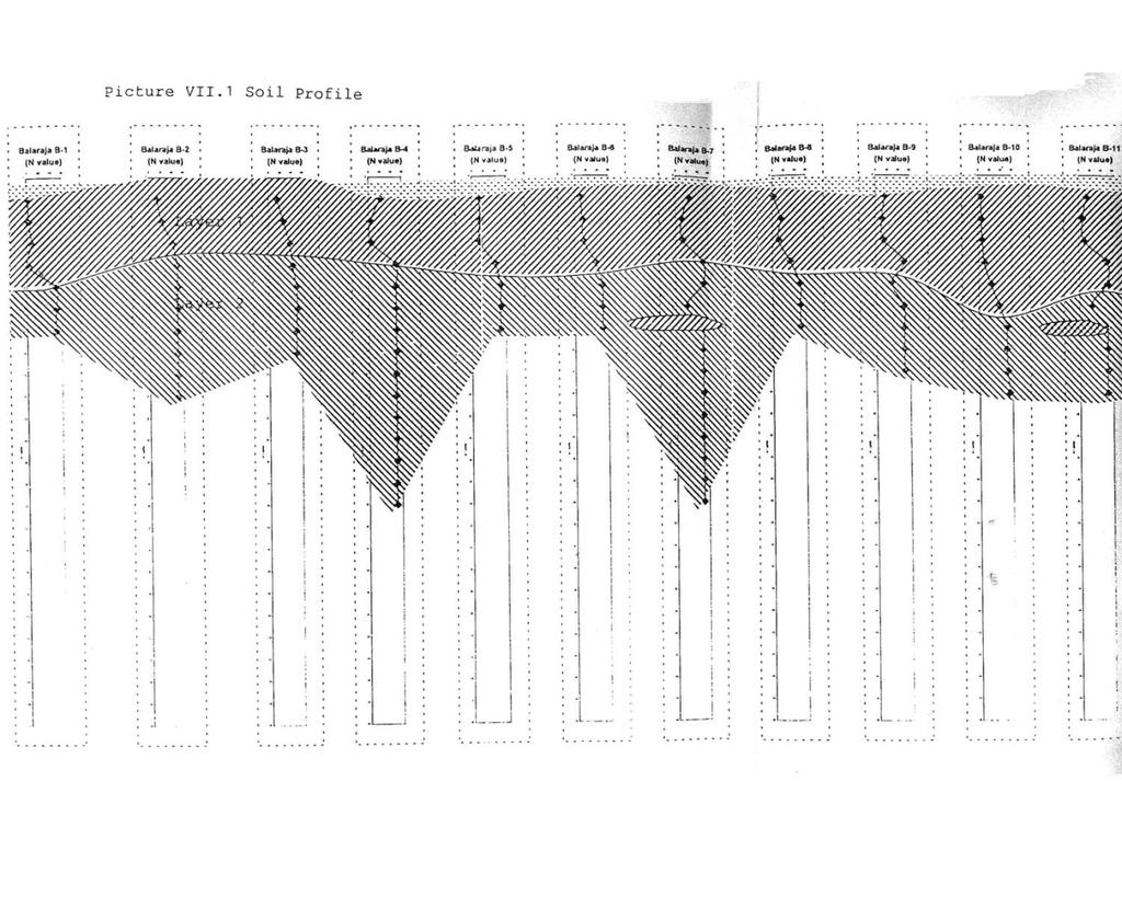
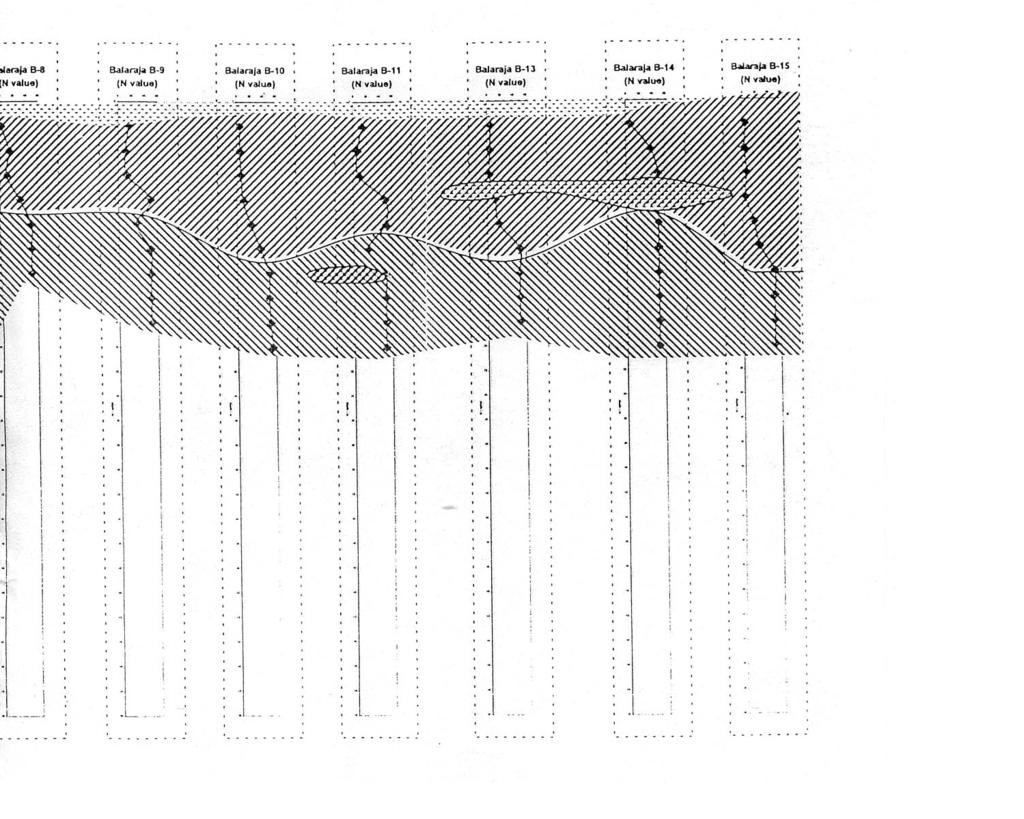
45 North Java Corridor Flyover Project BALARAJA FLYOVER DETAILED DESIGN SUBSTRUCTURE 3. SOIL PROPERTIES 3.. SOIL PROFILE 3.2. SUMMARY OF SPT S 3.3. SUMMARY OF UNDISTURBED TESTS 3.4. SUMMARY OF DISTURBED TESTS 3.5. SOIL SPRINGS AND LATERAL BEARING CAPACITY OBTAINED FROM SPT CORRELATIONS Katahira & Engineers International Page 57
46 North Java Corridor Flyover Project BALARAJA FLYOVER DETAILED DESIGN SUBSTRUCTURE 3. SOIL PROFILE Katahira & Engineers International Page 58
47 Page 59
2012 MECHANICS OF SOLIDS
 R10 SET - 1 II B.Tech II Semester, Regular Examinations, April 2012 MECHANICS OF SOLIDS (Com. to ME, AME, MM) Time: 3 hours Max. Marks: 75 Answer any FIVE Questions All Questions carry Equal Marks ~~~~~~~~~~~~~~~~~~~~~~
Name :. Roll No. :... Invigilator s Signature :.. CS/B.TECH (CE-NEW)/SEM-3/CE-301/ SOLID MECHANICS
/SEM-3/CE-301/ SOLID MECHANICS") Name :. Roll No. :..... Invigilator s Signature :.. 2011 SOLID MECHANICS Time Allotted : 3 Hours Full Marks : 70 The figures in the margin indicate full marks. Candidates are required to give their answers
Name :. Roll No. :..... Invigilator s Signature :.. 2011 SOLID MECHANICS Time Allotted : 3 Hours Full Marks : 70 The figures in the margin indicate full marks. Candidates are required to give their answers
Appendix J. Example of Proposed Changes
 Appendix J Example of Proposed Changes J.1 Introduction The proposed changes are illustrated with reference to a 200-ft, single span, Washington DOT WF bridge girder with debonded strands and no skew.
CHAPTER 6: ULTIMATE LIMIT STATE
 CHAPTER 6: ULTIMATE LIMIT STATE 6.1 GENERAL It shall be in accordance with JSCE Standard Specification (Design), 6.1. The collapse mechanism in statically indeterminate structures shall not be considered.
CIVIL DEPARTMENT MECHANICS OF STRUCTURES- ASSIGNMENT NO 1. Brach: CE YEAR:
 MECHANICS OF STRUCTURES- ASSIGNMENT NO 1 SEMESTER: V 1) Find the least moment of Inertia about the centroidal axes X-X and Y-Y of an unequal angle section 125 mm 75 mm 10 mm as shown in figure 2) Determine
ε t increases from the compressioncontrolled Figure 9.15: Adjusted interaction diagram
 CHAPTER NINE COLUMNS 4 b. The modified axial strength in compression is reduced to account for accidental eccentricity. The magnitude of axial force evaluated in step (a) is multiplied by 0.80 in case
Chapter. Materials. 1.1 Notations Used in This Chapter
 Chapter 1 Materials 1.1 Notations Used in This Chapter A Area of concrete cross-section C s Constant depending on the type of curing C t Creep coefficient (C t = ε sp /ε i ) C u Ultimate creep coefficient
KINGS COLLEGE OF ENGINEERING DEPARTMENT OF MECHANICAL ENGINEERING QUESTION BANK. Subject code/name: ME2254/STRENGTH OF MATERIALS Year/Sem:II / IV
 KINGS COLLEGE OF ENGINEERING DEPARTMENT OF MECHANICAL ENGINEERING QUESTION BANK Subject code/name: ME2254/STRENGTH OF MATERIALS Year/Sem:II / IV UNIT I STRESS, STRAIN DEFORMATION OF SOLIDS PART A (2 MARKS)
PERIYAR CENTENARY POLYTECHNIC COLLEGE PERIYAR NAGAR - VALLAM THANJAVUR. DEPARTMENT OF MECHANICAL ENGINEERING QUESTION BANK
 PERIYAR CENTENARY POLYTECHNIC COLLEGE PERIYAR NAGAR - VALLAM - 613 403 - THANJAVUR. DEPARTMENT OF MECHANICAL ENGINEERING QUESTION BANK Sub : Strength of Materials Year / Sem: II / III Sub Code : MEB 310
Annex - R C Design Formulae and Data
 The design formulae and data provided in this Annex are for education, training and assessment purposes only. They are based on the Hong Kong Code of Practice for Structural Use of Concrete 2013 (HKCP-2013).
3 Hours/100 Marks Seat No.
 *17304* 17304 14115 3 Hours/100 Marks Seat No. Instructions : (1) All questions are compulsory. (2) Illustrate your answers with neat sketches wherever necessary. (3) Figures to the right indicate full
: APPLIED MECHANICS & STRENGTH OF MATERIALS COURSE CODE : 4021 COURSE CATEGORY : A PERIODS/ WEEK : 5 PERIODS/ SEMESTER : 75 CREDIT : 5 TIME SCHEDULE
 COURSE TITLE : APPLIED MECHANICS & STRENGTH OF MATERIALS COURSE CODE : 4021 COURSE CATEGORY : A PERIODS/ WEEK : 5 PERIODS/ SEMESTER : 75 CREDIT : 5 TIME SCHEDULE MODULE TOPIC PERIODS 1 Simple stresses
QUESTION BANK SEMESTER: III SUBJECT NAME: MECHANICS OF SOLIDS
 QUESTION BANK SEMESTER: III SUBJECT NAME: MECHANICS OF SOLIDS UNIT 1- STRESS AND STRAIN PART A (2 Marks) 1. Define longitudinal strain and lateral strain. 2. State Hooke s law. 3. Define modular ratio,
QUESTION BANK DEPARTMENT: CIVIL SEMESTER: III SUBJECT CODE: CE2201 SUBJECT NAME: MECHANICS OF SOLIDS UNIT 1- STRESS AND STRAIN PART A
 DEPARTMENT: CIVIL SUBJECT CODE: CE2201 QUESTION BANK SEMESTER: III SUBJECT NAME: MECHANICS OF SOLIDS UNIT 1- STRESS AND STRAIN PART A (2 Marks) 1. Define longitudinal strain and lateral strain. 2. State
COURSE TITLE : APPLIED MECHANICS & STRENGTH OF MATERIALS COURSE CODE : 4017 COURSE CATEGORY : A PERIODS/WEEK : 6 PERIODS/ SEMESTER : 108 CREDITS : 5
 COURSE TITLE : APPLIED MECHANICS & STRENGTH OF MATERIALS COURSE CODE : 4017 COURSE CATEGORY : A PERIODS/WEEK : 6 PERIODS/ SEMESTER : 108 CREDITS : 5 TIME SCHEDULE MODULE TOPICS PERIODS 1 Simple stresses
SERVICEABILITY LIMIT STATE DESIGN
 CHAPTER 11 SERVICEABILITY LIMIT STATE DESIGN Article 49. Cracking Limit State 49.1 General considerations In the case of verifications relating to Cracking Limit State, the effects of actions comprise
Entrance exam Master Course
 - 1 - Guidelines for completion of test: On each page, fill in your name and your application code Each question has four answers while only one answer is correct. o Marked correct answer means 4 points
Lecture-04 Design of RC Members for Shear and Torsion
 Lecture-04 Design of RC Members for Shear and Torsion By: Prof. Dr. Qaisar Ali Civil Engineering Department UET Peshawar drqaisarali@uetpeshawar.edu.pk www.drqaisarali.com 1 Topics Addressed Design of
Visit Abqconsultants.com. This program Designs and Optimises RCC Chimney and Foundation. Written and programmed
 Prepared by : Date : Verified by : Date : Project : Ref Calculation Output Design of RCC Chimney :- 1) Dimensions of Chimney and Forces 200 Unit weight of Fire Brick Lining 19000 N/m3 100 Height of Fire
Design of AAC wall panel according to EN 12602
 Design of wall panel according to EN 160 Example 3: Wall panel with wind load 1.1 Issue Design of a wall panel at an industrial building Materials with a compressive strength 3,5, density class 500, welded
Downloaded from Downloaded from / 1
 PURWANCHAL UNIVERSITY III SEMESTER FINAL EXAMINATION-2002 LEVEL : B. E. (Civil) SUBJECT: BEG256CI, Strength of Material Full Marks: 80 TIME: 03:00 hrs Pass marks: 32 Candidates are required to give their
Roadway Grade = m, amsl HWM = Roadway grade dictates elevation of superstructure and not minimum free board requirement.
 Example on Design of Slab Bridge Design Data and Specifications Chapter 5 SUPERSTRUCTURES Superstructure consists of 10m slab, 36m box girder and 10m T-girder all simply supported. Only the design of Slab
9.5 Compression Members
 9.5 Compression Members This section covers the following topics. Introduction Analysis Development of Interaction Diagram Effect of Prestressing Force 9.5.1 Introduction Prestressing is meaningful when
Sabah Shawkat Cabinet of Structural Engineering Walls carrying vertical loads should be designed as columns. Basically walls are designed in
 Sabah Shawkat Cabinet of Structural Engineering 17 3.6 Shear walls Walls carrying vertical loads should be designed as columns. Basically walls are designed in the same manner as columns, but there are
UNIT 1 STRESS STRAIN AND DEFORMATION OF SOLIDS, STATES OF STRESS 1. Define stress. When an external force acts on a body, it undergoes deformation.
 UNIT 1 STRESS STRAIN AND DEFORMATION OF SOLIDS, STATES OF STRESS 1. Define stress. When an external force acts on a body, it undergoes deformation. At the same time the body resists deformation. The magnitude
Mechanics of Solids. Mechanics Of Solids. Suraj kr. Ray Department of Civil Engineering
 Mechanics Of Solids Suraj kr. Ray (surajjj2445@gmail.com) Department of Civil Engineering 1 Mechanics of Solids is a branch of applied mechanics that deals with the behaviour of solid bodies subjected
BE Semester- I ( ) Question Bank (MECHANICS OF SOLIDS)
 Question Bank (MECHANICS OF SOLIDS)") BE Semester- I ( ) Question Bank (MECHANICS OF SOLIDS) All questions carry equal marks(10 marks) Q.1 (a) Write the SI units of following quantities and also mention whether it is scalar or vector: (i)
BE Semester- I ( ) Question Bank (MECHANICS OF SOLIDS) All questions carry equal marks(10 marks) Q.1 (a) Write the SI units of following quantities and also mention whether it is scalar or vector: (i)
ISHIK UNIVERSITY DEPARTMENT OF MECHATRONICS ENGINEERING
 ISHIK UNIVERSITY DEPARTMENT OF MECHATRONICS ENGINEERING QUESTION BANK FOR THE MECHANICS OF MATERIALS-I 1. A rod 150 cm long and of diameter 2.0 cm is subjected to an axial pull of 20 kn. If the modulus
Mechanics of Structure
 S.Y. Diploma : Sem. III [CE/CS/CR/CV] Mechanics of Structure Time: Hrs.] Prelim Question Paper Solution [Marks : 70 Q.1(a) Attempt any SIX of the following. [1] Q.1(a) Define moment of Inertia. State MI
ME Final Exam. PROBLEM NO. 4 Part A (2 points max.) M (x) y. z (neutral axis) beam cross-sec+on. 20 kip ft. 0.2 ft. 10 ft. 0.1 ft.
 M (x) y. z (neutral axis) beam cross-sec+on. 20 kip ft. 0.2 ft. 10 ft. 0.1 ft.") ME 323 - Final Exam Name December 15, 2015 Instructor (circle) PROEM NO. 4 Part A (2 points max.) Krousgrill 11:30AM-12:20PM Ghosh 2:30-3:20PM Gonzalez 12:30-1:20PM Zhao 4:30-5:20PM M (x) y 20 kip ft 0.2
ME 323 - Final Exam Name December 15, 2015 Instructor (circle) PROEM NO. 4 Part A (2 points max.) Krousgrill 11:30AM-12:20PM Ghosh 2:30-3:20PM Gonzalez 12:30-1:20PM Zhao 4:30-5:20PM M (x) y 20 kip ft 0.2
UNIT-I STRESS, STRAIN. 1. A Member A B C D is subjected to loading as shown in fig determine the total elongation. Take E= 2 x10 5 N/mm 2
 UNIT-I STRESS, STRAIN 1. A Member A B C D is subjected to loading as shown in fig determine the total elongation. Take E= 2 x10 5 N/mm 2 Young s modulus E= 2 x10 5 N/mm 2 Area1=900mm 2 Area2=400mm 2 Area3=625mm
PURE BENDING. If a simply supported beam carries two point loads of 10 kn as shown in the following figure, pure bending occurs at segment BC.
 BENDING STRESS The effect of a bending moment applied to a cross-section of a beam is to induce a state of stress across that section. These stresses are known as bending stresses and they act normally
Seismic design of bridges
 NATIONAL TECHNICAL UNIVERSITY OF ATHENS LABORATORY FOR EARTHQUAKE ENGINEERING Seismic design of bridges Lecture 3 Ioannis N. Psycharis Capacity design Purpose To design structures of ductile behaviour
Bridge deck modelling and design process for bridges
 EU-Russia Regulatory Dialogue Construction Sector Subgroup 1 Bridge deck modelling and design process for bridges Application to a composite twin-girder bridge according to Eurocode 4 Laurence Davaine
Preferred practice on semi-integral abutment layout falls in the following order:
 GENERAL INFORMATION: This section of the chapter establishes the practices and requirements necessary for the design and detailing of semi-integral abutments. For general requirements and guidelines on
EXPERIMENTS ON SHEAR-FLEXURAL BEHAVIORS OF MODEL CAST IN PLACE CONCRETE PILES
 13 th World Conference on Earthquake Engineering Vancouver, B.C., Canada August 1-6, 2004 Paper No. 1403 EXPERIMENTS ON SHEAR-FLEXURAL BEHAVIORS OF MODEL CAST IN PLACE CONCRETE PILES Toshihiko YAMAMOTO
SRI CHANDRASEKHARENDRA SARASWATHI VISWA MAHAVIDHYALAYA
 SRI CHANDRASEKHARENDRA SARASWATHI VISWA MAHAVIDHYALAYA (Declared as Deemed-to-be University under Section 3 of the UGC Act, 1956, Vide notification No.F.9.9/92-U-3 dated 26 th May 1993 of the Govt. of
Sub. Code:
 Important Instructions to examiners: ) The answers should be examined by key words and not as word-to-word as given in the model answer scheme. ) The model answer and the answer written by candidate may
3.2 Reinforced Concrete Slabs Slabs are divided into suspended slabs. Suspended slabs may be divided into two groups:
 Sabah Shawkat Cabinet of Structural Engineering 017 3. Reinforced Concrete Slabs Slabs are divided into suspended slabs. Suspended slabs may be divided into two groups: (1) slabs supported on edges of
Seismic Pushover Analysis Using AASHTO Guide Specifications for LRFD Seismic Bridge Design
 Seismic Pushover Analysis Using AASHTO Guide Specifications for LRFD Seismic Bridge Design Elmer E. Marx, Alaska Department of Transportation and Public Facilities Michael Keever, California Department
UNIT I SIMPLE STRESSES AND STRAINS
 Subject with Code : SM-1(15A01303) Year & Sem: II-B.Tech & I-Sem SIDDHARTH GROUP OF INSTITUTIONS :: PUTTUR Siddharth Nagar, Narayanavanam Road 517583 QUESTION BANK (DESCRIPTIVE) UNIT I SIMPLE STRESSES
EUROCODE EN SEISMIC DESIGN OF BRIDGES
 Brussels, 18-20 February 2008 Dissemination of information workshop 1 EUROCODE EN1998-2 SEISMIC DESIGN OF BRIDGES Basil Kolias Basic Requirements Brussels, 18-20 February 2008 Dissemination of information
STRESS STRAIN AND DEFORMATION OF SOLIDS, STATES OF STRESS
 1 UNIT I STRESS STRAIN AND DEFORMATION OF SOLIDS, STATES OF STRESS 1. Define: Stress When an external force acts on a body, it undergoes deformation. At the same time the body resists deformation. The
NORMAL STRESS. The simplest form of stress is normal stress/direct stress, which is the stress perpendicular to the surface on which it acts.
 NORMAL STRESS The simplest form of stress is normal stress/direct stress, which is the stress perpendicular to the surface on which it acts. σ = force/area = P/A where σ = the normal stress P = the centric
R13. II B. Tech I Semester Regular Examinations, Jan MECHANICS OF SOLIDS (Com. to ME, AME, AE, MTE) PART-A
 PART-A") SET - 1 II B. Tech I Semester Regular Examinations, Jan - 2015 MECHANICS OF SOLIDS (Com. to ME, AME, AE, MTE) Time: 3 hours Max. Marks: 70 Note: 1. Question Paper consists of two parts (Part-A and Part-B)
SET - 1 II B. Tech I Semester Regular Examinations, Jan - 2015 MECHANICS OF SOLIDS (Com. to ME, AME, AE, MTE) Time: 3 hours Max. Marks: 70 Note: 1. Question Paper consists of two parts (Part-A and Part-B)
PLATE GIRDERS II. Load. Web plate Welds A Longitudinal elevation. Fig. 1 A typical Plate Girder
 16 PLATE GIRDERS II 1.0 INTRODUCTION This chapter describes the current practice for the design of plate girders adopting meaningful simplifications of the equations derived in the chapter on Plate Girders
Engineering Science OUTCOME 1 - TUTORIAL 4 COLUMNS
 Unit 2: Unit code: QCF Level: Credit value: 15 Engineering Science L/601/10 OUTCOME 1 - TUTORIAL COLUMNS 1. Be able to determine the behavioural characteristics of elements of static engineering systems
SERVICEABILITY OF BEAMS AND ONE-WAY SLABS
 CHAPTER REINFORCED CONCRETE Reinforced Concrete Design A Fundamental Approach - Fifth Edition Fifth Edition SERVICEABILITY OF BEAMS AND ONE-WAY SLABS A. J. Clark School of Engineering Department of Civil
PDDC 1 st Semester Civil Engineering Department Assignments of Mechanics of Solids [ ] Introduction, Fundamentals of Statics
![PDDC 1 st Semester Civil Engineering Department Assignments of Mechanics of Solids [ ] Introduction, Fundamentals of Statics](/thumbs/92/109382806.jpg "PDDC 1 st Semester Civil Engineering Department Assignments of Mechanics of Solids [ ] Introduction, Fundamentals of Statics") Page1 PDDC 1 st Semester Civil Engineering Department Assignments of Mechanics of Solids [2910601] Introduction, Fundamentals of Statics 1. Differentiate between Scalar and Vector quantity. Write S.I.
Page1 PDDC 1 st Semester Civil Engineering Department Assignments of Mechanics of Solids [2910601] Introduction, Fundamentals of Statics 1. Differentiate between Scalar and Vector quantity. Write S.I.
N = Shear stress / Shear strain
 UNIT - I 1. What is meant by factor of safety? [A/M-15] It is the ratio between ultimate stress to the working stress. Factor of safety = Ultimate stress Permissible stress 2. Define Resilience. [A/M-15]
Pre-stressed concrete = Pre-compression concrete Pre-compression stresses is applied at the place when tensile stress occur Concrete weak in tension
 Pre-stressed concrete = Pre-compression concrete Pre-compression stresses is applied at the place when tensile stress occur Concrete weak in tension but strong in compression Steel tendon is first stressed
Composite bridge design (EN1994-2) Bridge modelling and structural analysis
 Bridge modelling and structural analysis") EUROCODES Bridges: Background and applications Dissemination of information for training Vienna, 4-6 October 2010 1 Composite bridge design (EN1994-2) Bridge modelling and structural analysis Laurence
EUROCODES Bridges: Background and applications Dissemination of information for training Vienna, 4-6 October 2010 1 Composite bridge design (EN1994-2) Bridge modelling and structural analysis Laurence
Parametric analysis and torsion design charts for axially restrained RC beams
 Structural Engineering and Mechanics, Vol. 55, No. 1 (2015) 1-27 DOI: http://dx.doi.org/10.12989/sem.2015.55.1.001 1 Parametric analysis and torsion design charts for axially restrained RC beams Luís F.A.
18.Define the term modulus of resilience. May/June Define Principal Stress. 20. Define Hydrostatic Pressure.
 CE6306 STREGNTH OF MATERIALS Question Bank Unit-I STRESS, STRAIN, DEFORMATION OF SOLIDS PART-A 1. Define Poison s Ratio May/June 2009 2. What is thermal stress? May/June 2009 3. Estimate the load carried
Influence of residual stresses in the structural behavior of. tubular columns and arches. Nuno Rocha Cima Gomes
 October 2014 Influence of residual stresses in the structural behavior of Abstract tubular columns and arches Nuno Rocha Cima Gomes Instituto Superior Técnico, Universidade de Lisboa, Portugal Contact:
GATE SOLUTIONS E N G I N E E R I N G
 GATE SOLUTIONS C I V I L E N G I N E E R I N G From (1987-018) Office : F-16, (Lower Basement), Katwaria Sarai, New Delhi-110016 Phone : 011-65064 Mobile : 81309090, 9711853908 E-mail: info@iesmasterpublications.com,
Chapter Objectives. Design a beam to resist both bendingand shear loads
 Chapter Objectives Design a beam to resist both bendingand shear loads A Bridge Deck under Bending Action Castellated Beams Post-tensioned Concrete Beam Lateral Distortion of a Beam Due to Lateral Load
TABLE OF CONTANINET 1. Design criteria. 2. Lateral loads. 3. 3D finite element model (SAP2000, Ver.16). 4. Design of vertical elements (CSI, Ver.9).
. 4. Design of vertical elements (CSI, Ver.9).") TABLE OF CONTANINET 1. Design criteria. 2. Lateral loads. 2-1. Wind loads calculation 2-2. Seismic loads 3. 3D finite element model (SAP2000, Ver.16). 4. Design of vertical elements (CSI, Ver.9). 4-1.
TABLE OF CONTANINET 1. Design criteria. 2. Lateral loads. 2-1. Wind loads calculation 2-2. Seismic loads 3. 3D finite element model (SAP2000, Ver.16). 4. Design of vertical elements (CSI, Ver.9). 4-1.
Serviceability Limit States
 Serviceability Limit States www.eurocode2.info 1 Outline Crack control and limitations Crack width calculations Crack width calculation example Crack width calculation problem Restraint cracking Deflection
DEPARTMENT OF MECHANICAL ENIGINEERING, UNIVERSITY OF ENGINEERING & TECHNOLOGY LAHORE (KSK CAMPUS).
.") DEPARTMENT OF MECHANICAL ENIGINEERING, UNIVERSITY OF ENGINEERING & TECHNOLOGY LAHORE (KSK CAMPUS). Lab Director: Coordinating Staff: Mr. Muhammad Farooq (Lecturer) Mr. Liaquat Qureshi (Lab Supervisor)
DEPARTMENT OF MECHANICAL ENIGINEERING, UNIVERSITY OF ENGINEERING & TECHNOLOGY LAHORE (KSK CAMPUS). Lab Director: Coordinating Staff: Mr. Muhammad Farooq (Lecturer) Mr. Liaquat Qureshi (Lab Supervisor)
3.5 Analysis of Members under Flexure (Part IV)
") 3.5 Analysis o Members under Flexure (Part IV) This section covers the ollowing topics. Analysis o a Flanged Section 3.5.1 Analysis o a Flanged Section Introduction A beam can have langes or lexural eiciency.
3.5 Analysis o Members under Flexure (Part IV) This section covers the ollowing topics. Analysis o a Flanged Section 3.5.1 Analysis o a Flanged Section Introduction A beam can have langes or lexural eiciency.
CHAPTER 4: BENDING OF BEAMS
 (74) CHAPTER 4: BENDING OF BEAMS This chapter will be devoted to the analysis of prismatic members subjected to equal and opposite couples M and M' acting in the same longitudinal plane. Such members are
TABLE OF CONTENTS SECTION TITLE PAGE 2 PRINCIPLES OF SEISMIC ISOLATION OF BRIDGES 3
 TABLE OF CONTENTS SECTION TITLE PAGE 1 INTRODUCTION 1 2 PRINCIPLES OF SEISMIC ISOLATION OF BRIDGES 3 3 ANALYSIS METHODS OF SEISMICALLY ISOLATED BRIDGES 5 3.1 Introduction 5 3.2 Loadings for the Analysis
Only for Reference Page 1 of 18
 Only for Reference www.civilpddc2013.weebly.com Page 1 of 18 Seat No.: Enrolment No. GUJARAT TECHNOLOGICAL UNIVERSITY PDDC - SEMESTER II EXAMINATION WINTER 2013 Subject Code: X20603 Date: 26-12-2013 Subject
CHAPTER 3 THE EFFECTS OF FORCES ON MATERIALS
 CHAPTER THE EFFECTS OF FORCES ON MATERIALS EXERCISE 1, Page 50 1. A rectangular bar having a cross-sectional area of 80 mm has a tensile force of 0 kn applied to it. Determine the stress in the bar. Stress
S E C T I O N 1 2 P R O D U C T S E L E C T I O N G U I D E - H E L I C A L S C R E W P I L E F O U N D A T I O N S
 1. P R O D U C T S E L E C T I O N G U I D E - H E L I C A L S C R E W P I L E F O U N D A T I O N S Helical foundation pile includes a lead and extension(s). The lead section is made of a central steel
INELASTIC RESPONSES OF LONG BRIDGES TO ASYNCHRONOUS SEISMIC INPUTS
 13 th World Conference on Earthquake Engineering Vancouver, B.C., Canada August 1-6, 24 Paper No. 638 INELASTIC RESPONSES OF LONG BRIDGES TO ASYNCHRONOUS SEISMIC INPUTS Jiachen WANG 1, Athol CARR 1, Nigel
Lecture-05 Serviceability Requirements & Development of Reinforcement
 Lecture-05 Serviceability Requirements & Development of Reinforcement By: Prof Dr. Qaisar Ali Civil Engineering Department UET Peshawar drqaisarali@uetpeshawar.edu.pk www.drqaisarali.com 1 Section 1: Deflections
Sample Question Paper
 Scheme I Sample Question Paper Program Name : Mechanical Engineering Program Group Program Code : AE/ME/PG/PT/FG Semester : Third Course Title : Strength of Materials Marks : 70 Time: 3 Hrs. Instructions:
PES Institute of Technology
 PES Institute of Technology Bangalore south campus, Bangalore-5460100 Department of Mechanical Engineering Faculty name : Madhu M Date: 29/06/2012 SEM : 3 rd A SEC Subject : MECHANICS OF MATERIALS Subject
Flexure: Behavior and Nominal Strength of Beam Sections
 4 5000 4000 (increased d ) (increased f (increased A s or f y ) c or b) Flexure: Behavior and Nominal Strength of Beam Sections Moment (kip-in.) 3000 2000 1000 0 0 (basic) (A s 0.5A s ) 0.0005 0.001 0.0015
Design of Beams (Unit - 8)
") Design of Beams (Unit - 8) Contents Introduction Beam types Lateral stability of beams Factors affecting lateral stability Behaviour of simple and built - up beams in bending (Without vertical stiffeners)
Design of Beams (Unit - 8) Contents Introduction Beam types Lateral stability of beams Factors affecting lateral stability Behaviour of simple and built - up beams in bending (Without vertical stiffeners)
EARTHQUAKE SIMULATION TESTS OF BRIDGE COLUMN MODELS DAMAGED DURING 1995 KOBE EARTHQUAKE
 EARTHQUAKE SIMULATION TESTS OF BRIDGE COLUMN MODELS DAMAGED DURING 1995 KOBE EARTHQUAKE J. Sakai 1, S. Unjoh 2 and H. Ukon 3 1 Senior Researcher, Center for Advanced Engineering Structural Assessment and
CO~RSEOUTL..INE. revisedjune 1981 by G. Frech. of..a.pqij~t(..~ttsa.fidteconol.q.gy. Sault ",Ste'...:M~ri,e.: SAUl. ir.ft\,nl~t';~l' G ". E b:.
 -/ 1/ /.. SAUl. ir.ft\,nl~t';~l' G ". E b:.~~~~~, of..a.pqij~t(..~ttsa.fidteconol.q.gy. Sault ",Ste'...:M~ri,e.: ',' -.\'~. ~ ;:T.., CO~RSEOUTL..INE ARCHITECTURAL ENGINEERING II ARC 200-4 revisedjune 1981
HS-250 ( HOLLOW CORE SLAB )
") Type of slab : Design Data : Section : Slab thickness (d) ( mm ) 250 Effective width ( be ) ( mm ) 1180 No. of Core ( nc ) ( Ppcs. ) 6 Area of Core ( mm2 ) 20297.92 Spacing between core ( mm ) 40 Weight
Type of slab : Design Data : Section : Slab thickness (d) ( mm ) 250 Effective width ( be ) ( mm ) 1180 No. of Core ( nc ) ( Ppcs. ) 6 Area of Core ( mm2 ) 20297.92 Spacing between core ( mm ) 40 Weight
twenty one concrete construction: shear & deflection ARCHITECTURAL STRUCTURES: FORM, BEHAVIOR, AND DESIGN DR. ANNE NICHOLS SUMMER 2014 lecture
 ARCHITECTURAL STRUCTURES: FORM, BEHAVIOR, AND DESIGN DR. ANNE NICHOLS SUMMER 2014 lecture twenty one concrete construction: Copyright Kirk Martini shear & deflection Concrete Shear 1 Shear in Concrete
DESIGN AND DETAILING OF COUNTERFORT RETAINING WALL
 DESIGN AND DETAILING OF COUNTERFORT RETAINING WALL When the height of the retaining wall exceeds about 6 m, the thickness of the stem and heel slab works out to be sufficiently large and the design becomes
Design of a Balanced-Cantilever Bridge
 Design of a Balanced-Cantilever Bridge CL (Bridge is symmetric about CL) 0.8 L 0.2 L 0.6 L 0.2 L 0.8 L L = 80 ft Bridge Span = 2.6 L = 2.6 80 = 208 Bridge Width = 30 No. of girders = 6, Width of each girder
Civil Engineering Design (1) Design of Reinforced Concrete Columns 2006/7
 Design of Reinforced Concrete Columns 2006/7") Civil Engineering Design (1) Design of Reinforced Concrete Columns 2006/7 Dr. Colin Caprani, Chartered Engineer 1 Contents 1. Introduction... 3 1.1 Background... 3 1.2 Failure Modes... 5 1.3 Design Aspects...
Civil Engineering Design (1) Design of Reinforced Concrete Columns 2006/7 Dr. Colin Caprani, Chartered Engineer 1 Contents 1. Introduction... 3 1.1 Background... 3 1.2 Failure Modes... 5 1.3 Design Aspects...
Failure interaction curves for combined loading involving torsion, bending, and axial loading
 Failure interaction curves for combined loading involving torsion, bending, and axial loading W M Onsongo Many modern concrete structures such as elevated guideways are subjected to combined bending, torsion,
Delhi Noida Bhopal Hyderabad Jaipur Lucknow Indore Pune Bhubaneswar Kolkata Patna Web: Ph:
 Serial : IG1_CE_G_Concrete Structures_100818 Delhi Noida Bhopal Hyderabad Jaipur Lucknow Indore Pune Bhubaneswar Kolkata Patna Web: E-mail: info@madeeasy.in Ph: 011-451461 CLASS TEST 018-19 CIVIL ENGINEERING
Structural Steelwork Eurocodes Development of A Trans-national Approach
 Structural Steelwork Eurocodes Development of A Trans-national Approach Course: Eurocode Module 7 : Worked Examples Lecture 0 : Simple braced frame Contents: 1. Simple Braced Frame 1.1 Characteristic Loads
COURSE TITLE : THEORY OF STRUCTURES -I COURSE CODE : 3013 COURSE CATEGORY : B PERIODS/WEEK : 6 PERIODS/SEMESTER: 90 CREDITS : 6
 COURSE TITLE : THEORY OF STRUCTURES -I COURSE CODE : 0 COURSE CATEGORY : B PERIODS/WEEK : 6 PERIODS/SEMESTER: 90 CREDITS : 6 TIME SCHEDULE Module Topics Period Moment of forces Support reactions Centre
Tuesday, February 11, Chapter 3. Load and Stress Analysis. Dr. Mohammad Suliman Abuhaiba, PE
 1 Chapter 3 Load and Stress Analysis 2 Chapter Outline Equilibrium & Free-Body Diagrams Shear Force and Bending Moments in Beams Singularity Functions Stress Cartesian Stress Components Mohr s Circle for
THE STRUCTURAL DESIGN OF PILE FOUNDATIONS BASED ON LRFD FOR JAPANESE HIGHWAYS
 THE STRUCTURAL DESIGN OF PILE FOUNDATIONS BASED ON LRFD FOR JAPANESE HIGHWAYS Hideaki Nishida 1,Toshiaki Nanazawa 2, Masahiro Shirato 3, Tetsuya Kohno 4, and Mitsuaki Kitaura 5 Abstract One of the motivations
Purpose of this Guide: To thoroughly prepare students for the exact types of problems that will be on Exam 3.
 ES230 STRENGTH OF MTERILS Exam 3 Study Guide Exam 3: Wednesday, March 8 th in-class Updated 3/3/17 Purpose of this Guide: To thoroughly prepare students for the exact types of problems that will be on
Chapter 12. Static Equilibrium and Elasticity
 Chapter 12 Static Equilibrium and Elasticity Static Equilibrium Equilibrium implies that the object moves with both constant velocity and constant angular velocity relative to an observer in an inertial
NAME: Given Formulae: Law of Cosines: Law of Sines:
 NME: Given Formulae: Law of Cosines: EXM 3 PST PROBLEMS (LESSONS 21 TO 28) 100 points Thursday, November 16, 2017, 7pm to 9:30, Room 200 You are allowed to use a calculator and drawing equipment, only.
ENG1001 Engineering Design 1
 ENG1001 Engineering Design 1 Structure & Loads Determine forces that act on structures causing it to deform, bend, and stretch Forces push/pull on objects Structures are loaded by: > Dead loads permanent
INSTITUTE OF AERONAUTICAL ENGINEERING (Autonomous) Dundigal, Hyderabad
 Dundigal, Hyderabad") INSTITUTE OF AERONAUTICAL ENGINEERING (Autonomous) Dundigal, Hyderabad -00 04 CIVIL ENGINEERING QUESTION BANK Course Name : STRENGTH OF MATERIALS II Course Code : A404 Class : II B. Tech II Semester Section
INSTITUTE OF AERONAUTICAL ENGINEERING (Autonomous) Dundigal, Hyderabad -00 04 CIVIL ENGINEERING QUESTION BANK Course Name : STRENGTH OF MATERIALS II Course Code : A404 Class : II B. Tech II Semester Section
Detailing. Lecture 9 16 th November Reinforced Concrete Detailing to Eurocode 2
 Detailing Lecture 9 16 th November 2017 Reinforced Concrete Detailing to Eurocode 2 EC2 Section 8 - Detailing of Reinforcement - General Rules Bar spacing, Minimum bend diameter Anchorage of reinforcement
Part 1 is to be completed without notes, beam tables or a calculator. DO NOT turn Part 2 over until you have completed and turned in Part 1.
 NAME CM 3505 Fall 06 Test 2 Part 1 is to be completed without notes, beam tables or a calculator. Part 2 is to be completed after turning in Part 1. DO NOT turn Part 2 over until you have completed and
Slenderness Effects for Concrete Columns in Sway Frame - Moment Magnification Method (CSA A )
") Slenderness Effects for Concrete Columns in Sway Frame - Moment Magnification Method (CSA A23.3-94) Slender Concrete Column Design in Sway Frame Buildings Evaluate slenderness effect for columns in a
Slenderness Effects for Concrete Columns in Sway Frame - Moment Magnification Method (CSA A23.3-94) Slender Concrete Column Design in Sway Frame Buildings Evaluate slenderness effect for columns in a
Lecture-08 Gravity Load Analysis of RC Structures
 Lecture-08 Gravity Load Analysis of RC Structures By: Prof Dr. Qaisar Ali Civil Engineering Department UET Peshawar www.drqaisarali.com 1 Contents Analysis Approaches Point of Inflection Method Equivalent
 mportant nstructions to examiners: ) The answers should be examined by key words and not as word-to-word as given in the model answer scheme. ) The model answer and the answer written by candidate may
PUNCHING SHEAR CALCULATIONS 1 ACI 318; ADAPT-PT
 Structural Concrete Software System TN191_PT7_punching_shear_aci_4 011505 PUNCHING SHEAR CALCULATIONS 1 ACI 318; ADAPT-PT 1. OVERVIEW Punching shear calculation applies to column-supported slabs, classified
APPENDIX D SUMMARY OF EXISTING SIMPLIFIED METHODS
 APPENDIX D SUMMARY OF EXISTING SIMPLIFIED METHODS D-1 An extensive literature search revealed many methods for the calculation of live load distribution factors. This appendix will discuss, in detail,
Design of a Multi-Storied RC Building
 Design of a Multi-Storied RC Building 16 14 14 3 C 1 B 1 C 2 B 2 C 3 B 3 C 4 13 B 15 (S 1 ) B 16 (S 2 ) B 17 (S 3 ) B 18 7 B 4 B 5 B 6 B 7 C 5 C 6 C 7 C 8 C 9 7 B 20 B 22 14 B 19 (S 4 ) C 10 C 11 B 23
STRENGTH OF MATERIALS-I. Unit-1. Simple stresses and strains
 STRENGTH OF MATERIALS-I Unit-1 Simple stresses and strains 1. What is the Principle of surveying 2. Define Magnetic, True & Arbitrary Meridians. 3. Mention different types of chains 4. Differentiate between
High Tech High Top Hat Technicians. An Introduction to Solid Mechanics. Is that supposed to bend there?
 High Tech High Top Hat Technicians An Introduction to Solid Mechanics Or Is that supposed to bend there? Why don't we fall through the floor? The power of any Spring is in the same proportion with the