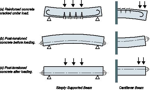
Pre-stressed concrete = Pre-compression concrete Pre-compression stresses is applied at the place when tensile stress occur Concrete weak in tension
|
|
|
- Madison Day
- 5 years ago
- Views:
Transcription


1
2 Pre-stressed concrete = Pre-compression concrete Pre-compression stresses is applied at the place when tensile stress occur Concrete weak in tension but strong in compression

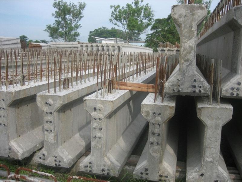
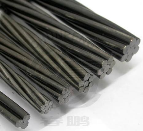
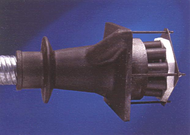
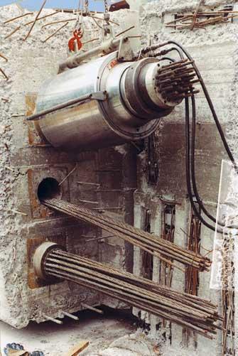
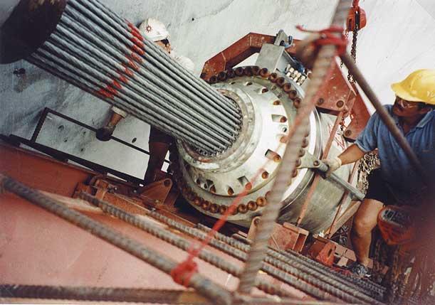
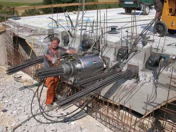
3 Steel tendon is first stressed Concrete is then poured After harden and reaching the required strength, the steel tendon is cut Pretension Posttension Concrete is first poured in the mould After harden, steel tendon is then stressed and anchored at both ends
4 Phase 1 Phase 2 Phase 3

5
6 Phase 1 Phase 2 Phase 3

7

8


 N/mm 2 Steel")
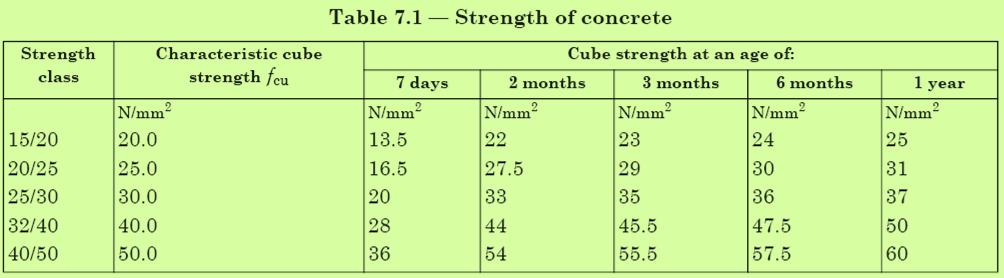
9 Concrete Between C30 and C60 Steel Tendon 7 or 19 nos of strand High workability during wet and high strength when hardened High strength steel Concrete strength at transfer, f ci 0.6f ck( t) N/mm 2 Steel strength usually 1650 N/mm 2
10
11 Section (3): MS EN : 2004

12

13
14
15
16 Stresses Loading Stage Transfer Service Symbol Value or Equation Symbol Value or Equation Compressive f ct 0.6f ck (t) f cs 0.6f ck Tensile f tt f ctm f ts 0
17 Some losses are immediate affecting the prestress force as soon as it transferred. Other losses occur gradually with time. Known as short-term and long-term losses, they include: Short-term (a) Elastic shortening of the concrete (b) Slip or movement of tendons at anchorage (c) Relaxation of prestressing steel (d) Friction at the bend due to curvature of tendons Long-term (a) Creep and shrinkage of the concrete under sustained compression (b) Relaxation of the prestressing steel under sustained tension
18 b Top fibre y t h y b e N.A Ungrouted duct Prestressing tendon Bottom fibre Reinforcement / bonded tendon
(h/2) (bh 3 /12) = 9.")
19 h = 500 mm w = 10 kn/m b = 200 mm y t f c 8 m y b _ f t M max = wl 2 /8 = 80 knm Tensile stress, f t = f c = M max /Z = M max y/i where I = bh 3 /12 and y t = y b = h/2 Therefore; f t = f c = (wl 2 /8)(h/2) (bh 3 /12) = 9.65 N/mm 2
20 Prestress force, P is then applied to eliminate tensile stress P N.A P f c = 9.65 N/mm 2 14 N/mm 2 _ f t = 9.64 N/mm 2 Stress due to loading P/A Stress due to force P = 0 N/mm 2 Total stress 9.65 P/A = 0 Prestress force, P required to eliminate tensile stress = 9.65A = 965 kn
21 If the prestress force, P applied is not at the centroid P e N.A P f c = 9.65 N/mm 2 _ f t = 9.65 N/mm 2 Stress due to loading P/A Pe/Z t Stress due to force P Pe/Z b = 14 N/mm 2 0 N/mm 2 Total stress 9.65 P/A Pe/Z = 0 Prestress force, P required to eliminate tensile stress = 9.65 / [(1/A) (e/z)] = 283 kn
22 (a) At Transfer M i = Moment due to self weight P e = Coefficient of short term losses P M i /Z t P/A Pe/Z t f 1t f tt _ = M i /Z b Stress due to self weight P/A Pe/Z b Stress due to force P f 2t f ct Total stress
23 (a) At Service w s kn/m (Service Load) P e = Coefficient of long term losses P M i /Z t M s /Z t P/A Pe/Z t = f 1s f cs M i /Z b M s /Z b P/A Pe/Z b f 2s f ts Stress due to self weight Stress due to w s kn/m Stress due to force P Total stress
24 From both Figures: At Transfer M i /Z t P/A Pe/Z t f tt (1) M i /Z b P/A Pe/Z b f ct (2) At Service M i /Z t M s /Z t P/A Pe/Z t f cs (3) M i /Z b M s /Z b P/A Pe/Z b f ts (4)
25 Rearranging Eqs. (1) (4): P/A(eA/Z t 1) M i /Z t f tt (5) P/A(eA/Z b 1) M i /Z b f ct (6) P/A(1 ea/z t ) M i /Z t M s /Z t f cs (7) P/A(1 ea/z b ) M i /Z b M s /Z b f ts (8)
26 w s = 20 kn/m P e 15 m P Rectangular beam = b h = mm. Prestress force, P = 2000 kn acted at e = 200 mm below centroid. The short-term and long-term losses of the prestress are 10% and 20%, respectively. (a) If f ck = 40 N/mm 2 draw the stress distribution diagram at midspan during transfer and service. Also check that these stresses are within the allowable limits.
27 Cross sectional area, A c = b h = = mm 2 Moment of inertia, I xx = bh 3 /12 = /12 = mm 4 Modulus of section, Z t = Z b = I xx /y = / 475 = mm 3
28 Stress limit for f ck = 40 N/mm 2 and f ci = 28 N/mm 2 At Transfer f ct = 0.6f ck (t) = 0.6(28) = 16.8 N/mm 2 f tt = f ctm = 0.30 (28) 2/3 = 2.77 N/mm 2 At Service f cs = 0.6f ck = 0.6(40) = 24.0 N/mm 2 f ts = 0.0 N/mm 2
29 At Transfer Stress Distribution Self weight, w i = (A c )(25) = ( )(25) 10-6 = 7.12 kn/m M i at mid-span = w i L 2 /8 = (7.12)(15 2 )/8 = knm Short-term losses, = (1 0.10) = 0.90 Stress at top fibre f 1t = M i /Z t P/A Pe/Z t = 5.20 N/mm 2 Stress at bottom fibre f 2t = M i /Z b P/A Pe/Z b = N/mm 2 f 1t ( 5.20) f tt ( 2.77) _ f 2t (17.84) f ct (16.8) PASS FAIL
30 At Service Stress Distribution Service load, w s = 20 kn/m M s at mid-span = w s L 2 /8 = (20)(15 2 )/8 = knm Long-term losses, = (1 0.20) = 0.80 Stress at top fibre f 1s = M i /Z t M s /Z t P/A Pe/Z t = 8.33 N/mm 2 Stress at bottom fibre f 1s (8.33) f cs (24.0) PASS f 2s = M i /Z b M s /Z b P/A Pe/Z b = 3.23 N/mm 2 _ f 2k ( 3.23) f ts (0) PASS
31 Eq. (5) Eq. (7) M i /Z t M i /Z t M s /Z t ( f cs f tt ) Z t ( )M i M s ( f cs f tt ) (9) Eq. (6) Eq. (8) M i /Z b M i /Z b M s /Z b ( f ts f ct ) Z b ( )M i M s ( f ts f ct ) (10)

32 A prestressed concrete beam with an effective length of 20 m is simply supported at both ends. During service, a characteristics load 20 kn/m is applied to the beam apart from its self weight. The concrete strength is 50 N/mm 2 and the transfer is done when the concrete achieve the strength of 30 N/mm 2. The prestressing force applied is 2000 kn at the eccentricity of 500 mm at mid-span. The short-term and long-term losses is 10% and 20%, respectively. Design the suitable beam cross section if a rectangular section is used.
33 Stress limit; At Transfer f ct = 0.6f ck (t) = 0.6(30) = 18.0 N/mm 2 f tt = f ctm = 0.30 (30) 2/3 = 2.90 N/mm 2 At Service f cs = 0.6f ck = 0.6(50) = 30.0 N/mm 2 f ts = 0.0 N/mm 2
34 M s = (20) 20 2 /8 = 1000 knm (not including the self weight) From Eq. (9): ( f cs f tt ) = 0.9(30) 0.8(2.90) = N/mm 2 Z t ( )M i M s ( f cs f tt ) Z t (0.1M i 900) 10 6 / From Eq. (10): ( f ts f ct ) = 0.9(0) 0.8(18.0) = 14.4 N/mm 2 Z b ( )M i M s ( f ts f ct ) Z b (0.1M i 900) 10 6 / 14.4 Since Z b Z t, only Z b is used & checked to find the suitable cross section of the beam
35 For rectangular cross section Z t = Z b = I xx /y = bh 3 /12 (h/2) = bh 2 /6 Try 300 mm 1000 mm Self weight, w i = = 7.5 kn/m Moment due to self weight, M i = 375 knm Z b ( ) 10 6 / mm 3 Z = /6 = mm 3 Z b Increase size
36 Try 300 mm 1400 mm Self weight, w i = = 10.5 kn/m Moment due to self weight, M i = 525 knm Z b ( ) 10 6 / mm 3 Z = /6 = mm 3 Z b OK

37 TARMAC TOPFLOOR

38 TARMAC TOPFLOOR
39
40


41
PURE BENDING. If a simply supported beam carries two point loads of 10 kn as shown in the following figure, pure bending occurs at segment BC.
 BENDING STRESS The effect of a bending moment applied to a cross-section of a beam is to induce a state of stress across that section. These stresses are known as bending stresses and they act normally
9.5 Compression Members
 9.5 Compression Members This section covers the following topics. Introduction Analysis Development of Interaction Diagram Effect of Prestressing Force 9.5.1 Introduction Prestressing is meaningful when
Delhi Noida Bhopal Hyderabad Jaipur Lucknow Indore Pune Bhubaneswar Kolkata Patna Web: Ph:
 Serial : IG1_CE_G_Concrete Structures_100818 Delhi Noida Bhopal Hyderabad Jaipur Lucknow Indore Pune Bhubaneswar Kolkata Patna Web: E-mail: info@madeeasy.in Ph: 011-451461 CLASS TEST 018-19 CIVIL ENGINEERING
Bending Stress. Sign convention. Centroid of an area
 Bending Stress Sign convention The positive shear force and bending moments are as shown in the figure. Centroid of an area Figure 40: Sign convention followed. If the area can be divided into n parts
Chapter. Materials. 1.1 Notations Used in This Chapter
 Chapter 1 Materials 1.1 Notations Used in This Chapter A Area of concrete cross-section C s Constant depending on the type of curing C t Creep coefficient (C t = ε sp /ε i ) C u Ultimate creep coefficient
SPECIFIC VERIFICATION Chapter 5
 As = 736624/(0.5*413.69) = 3562 mm 2 (ADAPT 3569 mm 2, B29, C6) Data Block 27 - Compressive Stresses The initial compressive strength, f ci, is the strength entered in the Material/Concrete input screen.
ε t increases from the compressioncontrolled Figure 9.15: Adjusted interaction diagram
 CHAPTER NINE COLUMNS 4 b. The modified axial strength in compression is reduced to account for accidental eccentricity. The magnitude of axial force evaluated in step (a) is multiplied by 0.80 in case
Serviceability Deflection calculation
 Chp-6:Lecture Goals Serviceability Deflection calculation Deflection example Structural Design Profession is concerned with: Limit States Philosophy: Strength Limit State (safety-fracture, fatigue, overturning
3.5 Analysis of Members under Flexure (Part IV)
") 3.5 Analysis o Members under Flexure (Part IV) This section covers the ollowing topics. Analysis o a Flanged Section 3.5.1 Analysis o a Flanged Section Introduction A beam can have langes or lexural eiciency.
3.5 Analysis o Members under Flexure (Part IV) This section covers the ollowing topics. Analysis o a Flanged Section 3.5.1 Analysis o a Flanged Section Introduction A beam can have langes or lexural eiciency.
 mportant nstructions to examiners: ) The answers should be examined by key words and not as word-to-word as given in the model answer scheme. ) The model answer and the answer written by candidate may
Dr. Hazim Dwairi. Example: Continuous beam deflection
 Example: Continuous beam deflection Analyze the short-term and ultimate long-term deflections of end-span of multi-span beam shown below. Ignore comp steel Beam spacing = 3000 mm b eff = 9000/4 = 2250
CHAPTER 4. Stresses in Beams
 CHAPTER 4 Stresses in Beams Problem 1. A rolled steel joint (RSJ) of -section has top and bottom flanges 150 mm 5 mm and web of size 00 mm 1 mm. t is used as a simply supported beam over a span of 4 m
Software Verification
 PROGRAM NAME: SAFE 014 EXAMPLE 16 racked Slab Analysis RAKED ANALYSIS METHOD The moment curvature diagram shown in Figure 16-1 depicts a plot of the uncracked and cracked conditions, 1 State 1, and, State,
A.2 AASHTO Type IV, LRFD Specifications
 A.2 AASHTO Type IV, LRFD Specifications A.2.1 INTRODUCTION A.2.2 DESIGN PARAMETERS 1'-5.0" Detailed example showing sample calculations for design of typical Interior AASHTO Type IV prestressed concrete
Mechanics of Structure
 S.Y. Diploma : Sem. III [CE/CS/CR/CV] Mechanics of Structure Time: Hrs.] Prelim Question Paper Solution [Marks : 70 Q.1(a) Attempt any SIX of the following. [1] Q.1(a) Define moment of Inertia. State MI
 UNIT III DEFLECTION OF BEAMS 1. What are the methods for finding out the slope and deflection at a section? The important methods used for finding out the slope and deflection at a section in a loaded
Design of AAC wall panel according to EN 12602
 Design of wall panel according to EN 160 Example 3: Wall panel with wind load 1.1 Issue Design of a wall panel at an industrial building Materials with a compressive strength 3,5, density class 500, welded
CIVIL DEPARTMENT MECHANICS OF STRUCTURES- ASSIGNMENT NO 1. Brach: CE YEAR:
 MECHANICS OF STRUCTURES- ASSIGNMENT NO 1 SEMESTER: V 1) Find the least moment of Inertia about the centroidal axes X-X and Y-Y of an unequal angle section 125 mm 75 mm 10 mm as shown in figure 2) Determine
Appendix J. Example of Proposed Changes
 Appendix J Example of Proposed Changes J.1 Introduction The proposed changes are illustrated with reference to a 200-ft, single span, Washington DOT WF bridge girder with debonded strands and no skew.
Software Verification
 EXAMPLE 16 racked Slab Analysis RAKED ANALYSIS METHOD The moment curvature diagram shown in Figure 16-1 depicts a plot of the uncracked and cracked conditions, Ψ 1 State 1, and, Ψ State, for a reinforced
SERVICEABILITY LIMIT STATE DESIGN
 CHAPTER 11 SERVICEABILITY LIMIT STATE DESIGN Article 49. Cracking Limit State 49.1 General considerations In the case of verifications relating to Cracking Limit State, the effects of actions comprise
Stress Analysis Lecture 4 ME 276 Spring Dr./ Ahmed Mohamed Nagib Elmekawy
 Stress Analysis Lecture 4 ME 76 Spring 017-018 Dr./ Ahmed Mohamed Nagib Elmekawy Shear and Moment Diagrams Beam Sign Convention The positive directions are as follows: The internal shear force causes a
OUTCOME 1 - TUTORIAL 3 BENDING MOMENTS. You should judge your progress by completing the self assessment exercises. CONTENTS
 Unit 2: Unit code: QCF Level: 4 Credit value: 15 Engineering Science L/601/1404 OUTCOME 1 - TUTORIAL 3 BENDING MOMENTS 1. Be able to determine the behavioural characteristics of elements of static engineering
Creep and Shrinkage Calculation of a Rectangular Prestressed Concrete CS
 Benchmark Example No. 18 SOFiSTiK 2018 VERiFiCATiON MANUAL DCE-EN18: VERiFiCATiON MANUAL, Version 2018-9 Software Version: SOFiSTiK 2018 Copyright 2019 by SOFiSTiK AG, Oberschleissheim, Germany. SOFiSTiK
Serviceability Limit States
 Serviceability Limit States www.eurocode2.info 1 Outline Crack control and limitations Crack width calculations Crack width calculation example Crack width calculation problem Restraint cracking Deflection
STRENGTH OF MATERIALS-I. Unit-1. Simple stresses and strains
 STRENGTH OF MATERIALS-I Unit-1 Simple stresses and strains 1. What is the Principle of surveying 2. Define Magnetic, True & Arbitrary Meridians. 3. Mention different types of chains 4. Differentiate between
Sub. Code:
 Important Instructions to examiners: ) The answers should be examined by key words and not as word-to-word as given in the model answer scheme. ) The model answer and the answer written by candidate may
Entrance exam Master Course
 - 1 - Guidelines for completion of test: On each page, fill in your name and your application code Each question has four answers while only one answer is correct. o Marked correct answer means 4 points
UNIVERSITY OF BOLTON SCHOOL OF ENGINEERING. BEng (HONS) CIVIL ENGINEERING SEMESTER 1 EXAMINATION 2016/2017 MATHEMATICS & STRUCTURAL ANALYSIS
 CIVIL ENGINEERING SEMESTER 1 EXAMINATION 2016/2017 MATHEMATICS & STRUCTURAL ANALYSIS") TW21 UNIVERSITY OF BOLTON SCHOOL OF ENGINEERING BEng (HONS) CIVIL ENGINEERING SEMESTER 1 EXAMINATION 2016/2017 MATHEMATICS & STRUCTURAL ANALYSIS MODULE NO: CIE4011 Date: Wednesday 11 th January 2017 Time:
TW21 UNIVERSITY OF BOLTON SCHOOL OF ENGINEERING BEng (HONS) CIVIL ENGINEERING SEMESTER 1 EXAMINATION 2016/2017 MATHEMATICS & STRUCTURAL ANALYSIS MODULE NO: CIE4011 Date: Wednesday 11 th January 2017 Time:
10/14/2011. Types of Shear Failure. CASE 1: a v /d 6. a v. CASE 2: 2 a v /d 6. CASE 3: a v /d 2
 V V Types o Shear Failure a v CASE 1: a v /d 6 d V a v CASE 2: 2 a v /d 6 d V a v CASE 3: a v /d 2 d V 1 Shear Resistance Concrete compression d V cz = Shear orce in the compression zone (20 40%) V a =
3.5 Reinforced Concrete Section Properties
 CHAPER 3: Reinforced Concrete Slabs and Beams 3.5 Reinforced Concrete Section Properties Description his application calculates gross section moment of inertia neglecting reinforcement, moment of inertia
BE Semester- I ( ) Question Bank (MECHANICS OF SOLIDS)
 Question Bank (MECHANICS OF SOLIDS)") BE Semester- I ( ) Question Bank (MECHANICS OF SOLIDS) All questions carry equal marks(10 marks) Q.1 (a) Write the SI units of following quantities and also mention whether it is scalar or vector: (i)
BE Semester- I ( ) Question Bank (MECHANICS OF SOLIDS) All questions carry equal marks(10 marks) Q.1 (a) Write the SI units of following quantities and also mention whether it is scalar or vector: (i)
CHAPTER 6: ULTIMATE LIMIT STATE
 CHAPTER 6: ULTIMATE LIMIT STATE 6.1 GENERAL It shall be in accordance with JSCE Standard Specification (Design), 6.1. The collapse mechanism in statically indeterminate structures shall not be considered.
MECHANICS OF MATERIALS Sample Problem 4.2
 Sample Problem 4. SOLUTON: Based on the cross section geometry, calculate the location of the section centroid and moment of inertia. ya ( + Y Ad ) A A cast-iron machine part is acted upon by a kn-m couple.
SERVICEABILITY OF BEAMS AND ONE-WAY SLABS
 CHAPTER REINFORCED CONCRETE Reinforced Concrete Design A Fundamental Approach - Fifth Edition Fifth Edition SERVICEABILITY OF BEAMS AND ONE-WAY SLABS A. J. Clark School of Engineering Department of Civil
Bridge deck modelling and design process for bridges
 EU-Russia Regulatory Dialogue Construction Sector Subgroup 1 Bridge deck modelling and design process for bridges Application to a composite twin-girder bridge according to Eurocode 4 Laurence Davaine
Part 1 is to be completed without notes, beam tables or a calculator. DO NOT turn Part 2 over until you have completed and turned in Part 1.
 NAME CM 3505 Fall 06 Test 2 Part 1 is to be completed without notes, beam tables or a calculator. Part 2 is to be completed after turning in Part 1. DO NOT turn Part 2 over until you have completed and
2012 MECHANICS OF SOLIDS
 R10 SET - 1 II B.Tech II Semester, Regular Examinations, April 2012 MECHANICS OF SOLIDS (Com. to ME, AME, MM) Time: 3 hours Max. Marks: 75 Answer any FIVE Questions All Questions carry Equal Marks ~~~~~~~~~~~~~~~~~~~~~~
NATIONAL PROGRAM ON TECHNOLOGY ENHANCED LEARNING (NPTEL) IIT MADRAS Offshore structures under special environmental loads including fire-resistance
 IIT MADRAS Offshore structures under special environmental loads including fire-resistance") Week Eight: Advanced structural analyses Tutorial Eight Part A: Objective questions (5 marks) 1. theorem is used to derive deflection of curved beams with small initial curvature (Castigliano's theorem)
Week Eight: Advanced structural analyses Tutorial Eight Part A: Objective questions (5 marks) 1. theorem is used to derive deflection of curved beams with small initial curvature (Castigliano's theorem)
DESIGN OF STAIRCASE. Dr. Izni Syahrizal bin Ibrahim. Faculty of Civil Engineering Universiti Teknologi Malaysia
 DESIGN OF STAIRCASE Dr. Izni Syahrizal bin Ibrahim Faculty of Civil Engineering Universiti Teknologi Malaysia Email: iznisyahrizal@utm.my Introduction T N T G N G R h Flight Span, L Landing T = Thread
PROPOSED SATSANG HALL TECHNICAL REPORT
 PROPOSED SATSANG HALL - VERTICAL STRIP V1 1 ------------------------------------------------------------------------------ ADAPT CORPORATION STRUCTURAL CONCRETE SOFTWARE SYSTEM 1733 Woodside Road, Suite
Neutral Axis Depth for a Reinforced Concrete Section. Under Eccentric Axial Load
 Neutral Axis Depth for a Reinforced Concrete Section Doug Jenkins; Interactive Design Services Pty Ltd Under Eccentric Axial Load To determine the stresses in a reinforced concrete section we must first
Name :. Roll No. :... Invigilator s Signature :.. CS/B.TECH (CE-NEW)/SEM-3/CE-301/ SOLID MECHANICS
/SEM-3/CE-301/ SOLID MECHANICS") Name :. Roll No. :..... Invigilator s Signature :.. 2011 SOLID MECHANICS Time Allotted : 3 Hours Full Marks : 70 The figures in the margin indicate full marks. Candidates are required to give their answers
Name :. Roll No. :..... Invigilator s Signature :.. 2011 SOLID MECHANICS Time Allotted : 3 Hours Full Marks : 70 The figures in the margin indicate full marks. Candidates are required to give their answers
PERIYAR CENTENARY POLYTECHNIC COLLEGE PERIYAR NAGAR - VALLAM THANJAVUR. DEPARTMENT OF MECHANICAL ENGINEERING QUESTION BANK
 PERIYAR CENTENARY POLYTECHNIC COLLEGE PERIYAR NAGAR - VALLAM - 613 403 - THANJAVUR. DEPARTMENT OF MECHANICAL ENGINEERING QUESTION BANK Sub : Strength of Materials Year / Sem: II / III Sub Code : MEB 310
FIXED BEAMS IN BENDING
 FIXED BEAMS IN BENDING INTRODUCTION Fixed or built-in beams are commonly used in building construction because they possess high rigidity in comparison to simply supported beams. When a simply supported
DISTRIBUTION OF STRESS IN GROUND-SUPPORTED SLABS
 Structural Concrete Software System TN207_sog_stresses_10 122005 DISTRIBUTION OF STRESS IN GROUND-SUPPORTED SLABS Bijan O Aalami 1 This Technical Note describes the distribution of stress in ground-supported
Final Report. Predicting of the stiffness of cracked reinforced concrete structure. Author: Yongzhen Li
 Predicting of the stiffness of cracked reinforced concrete structure Final Report Predicting of the Stiffness of Cracked Reinforced Concrete Structures Author: 1531344 Delft University of Technology Faculty
Design of reinforced concrete sections according to EN and EN
 Design of reinforced concrete sections according to EN 1992-1-1 and EN 1992-2 Validation Examples Brno, 21.10.2010 IDEA RS s.r.o. South Moravian Innovation Centre, U Vodarny 2a, 616 00 BRNO tel.: +420-511
Strength of Materials Prof: S.K.Bhattacharya Dept of Civil Engineering, IIT, Kharagpur Lecture no 28 Stresses in Beams- III
 Strength of Materials Prof: S.K.Bhattacharya Dept of Civil Engineering, IIT, Kharagpur Lecture no 28 Stresses in Beams- III Welcome to the 3 rd lesson of the 6 th module which is on Stresses in Beams part
TIME-DEPENDENT ANALYSIS OF PARTIALLY PRESTRESSED CONTINUOUS COMPOSITE BEAMS
 2nd Int. PhD Symposium in Civil Engineering 998 Budapest IME-DEPENDEN ANAYSIS OF PARIAY PRESRESSED CONINUOUS COMPOSIE BEAMS M. Sar and Assoc. Prof. J. apos 2 Slova echnical University, Faculty of Civil
Sample Question Paper
 Scheme I Sample Question Paper Program Name : Mechanical Engineering Program Group Program Code : AE/ME/PG/PT/FG Semester : Third Course Title : Strength of Materials Marks : 70 Time: 3 Hrs. Instructions:
Hardened Concrete. Lecture No. 16
 Hardened Concrete Lecture No. 16 Fatigue strength of concrete Modulus of elasticity, Creep Shrinkage of concrete Stress-Strain Plot of Concrete At stress below 30% of ultimate strength, the transition
Chapter (6) Geometric Design of Shallow Foundations
 Geometric Design of Shallow Foundations") Chapter (6) Geometric Design of Shallow Foundations Introduction As we stated in Chapter 3, foundations are considered to be shallow if if [D (3 4)B]. Shallow foundations have several advantages: minimum
Chapter (6) Geometric Design of Shallow Foundations Introduction As we stated in Chapter 3, foundations are considered to be shallow if if [D (3 4)B]. Shallow foundations have several advantages: minimum
= 50 ksi. The maximum beam deflection Δ max is not = R B. = 30 kips. Notes for Strength of Materials, ET 200
 Notes for Strength of Materials, ET 00 Steel Six Easy Steps Steel beam design is about selecting the lightest steel beam that will support the load without exceeding the bending strength or shear strength
Note: For further information, including the development of creep with time, Annex B may be used.
 ..4 Creep and shrinkage ()P Creep and shrinkage of the concrete depend on the ambient humidity, the dimensions of the element and the composition of the concrete. Creep is also influenced by the maturity
CHAPTER 4: BENDING OF BEAMS
 (74) CHAPTER 4: BENDING OF BEAMS This chapter will be devoted to the analysis of prismatic members subjected to equal and opposite couples M and M' acting in the same longitudinal plane. Such members are
3 Hours/100 Marks Seat No.
 *17304* 17304 14115 3 Hours/100 Marks Seat No. Instructions : (1) All questions are compulsory. (2) Illustrate your answers with neat sketches wherever necessary. (3) Figures to the right indicate full
1. ARRANGEMENT. a. Frame A1-P3. L 1 = 20 m H = 5.23 m L 2 = 20 m H 1 = 8.29 m L 3 = 20 m H 2 = 8.29 m H 3 = 8.39 m. b. Frame P3-P6
 Page 3 Page 4 Substructure Design. ARRANGEMENT a. Frame A-P3 L = 20 m H = 5.23 m L 2 = 20 m H = 8.29 m L 3 = 20 m H 2 = 8.29 m H 3 = 8.39 m b. Frame P3-P6 L = 25 m H 3 = 8.39 m L 2 = 3 m H 4 = 8.5 m L
THEME IS FIRST OCCURANCE OF YIELDING THE LIMIT?
 CIE309 : PLASTICITY THEME IS FIRST OCCURANCE OF YIELDING THE LIMIT? M M - N N + + σ = σ = + f f BENDING EXTENSION Ir J.W. Welleman page nr 0 kn Normal conditions during the life time WHAT HAPPENS DUE TO
Composite bridge design (EN1994-2) Bridge modelling and structural analysis
 Bridge modelling and structural analysis") EUROCODES Bridges: Background and applications Dissemination of information for training Vienna, 4-6 October 2010 1 Composite bridge design (EN1994-2) Bridge modelling and structural analysis Laurence
EUROCODES Bridges: Background and applications Dissemination of information for training Vienna, 4-6 October 2010 1 Composite bridge design (EN1994-2) Bridge modelling and structural analysis Laurence
This procedure covers the determination of the moment of inertia about the neutral axis.
 327 Sample Problems Problem 16.1 The moment of inertia about the neutral axis for the T-beam shown is most nearly (A) 36 in 4 (C) 236 in 4 (B) 136 in 4 (D) 736 in 4 This procedure covers the determination
CH. 4 BEAMS & COLUMNS
 CH. 4 BEAMS & COLUMNS BEAMS Beams Basic theory of bending: internal resisting moment at any point in a beam must equal the bending moments produced by the external loads on the beam Rx = Cc + Tt - If the
CIV100 Mechanics. Module 5: Internal Forces and Design. by: Jinyue Zhang. By the end of this Module you should be able to:
 CIV100 Mechanics Module 5: Internal Forces and Design by: Jinyue Zhang Module Objective By the end of this Module you should be able to: Find internal forces of any structural members Understand how Shear
Module 14. Tension Members. Version 2 CE IIT, Kharagpur
 Module 14 Tension Members Lesson 37 Numerical Problems Instructional Objectives: At the end of this lesson, the student should be able to: select the category of the problem if it is a liquid retaining
Homework No. 1 MAE/CE 459/559 John A. Gilbert, Ph.D. Fall 2004
 Homework No. 1 MAE/CE 459/559 John A. Gilbert, Ph.D. 1. A beam is loaded as shown. The dimensions of the cross section appear in the insert. the figure. Draw a complete free body diagram showing an equivalent
Design of Steel Structures Prof. S.R.Satish Kumar and Prof. A.R.Santha Kumar
 5.10 Examples 5.10.1 Analysis of effective section under compression To illustrate the evaluation of reduced section properties of a section under axial compression. Section: 00 x 80 x 5 x 4.0 mm Using
Mechanics of Solids notes
 Mechanics of Solids notes 1 UNIT II Pure Bending Loading restrictions: As we are aware of the fact internal reactions developed on any cross-section of a beam may consists of a resultant normal force,
DESIGN AND DETAILING OF COUNTERFORT RETAINING WALL
 DESIGN AND DETAILING OF COUNTERFORT RETAINING WALL When the height of the retaining wall exceeds about 6 m, the thickness of the stem and heel slab works out to be sufficiently large and the design becomes
PUNCHING SHEAR CALCULATIONS 1 ACI 318; ADAPT-PT
 Structural Concrete Software System TN191_PT7_punching_shear_aci_4 011505 PUNCHING SHEAR CALCULATIONS 1 ACI 318; ADAPT-PT 1. OVERVIEW Punching shear calculation applies to column-supported slabs, classified
CE5510 Advanced Structural Concrete Design - Design & Detailing of Openings in RC Flexural Members-
 CE5510 Advanced Structural Concrete Design - Design & Detailing Openings in RC Flexural Members- Assoc Pr Tan Kiang Hwee Department Civil Engineering National In this lecture DEPARTMENT OF CIVIL ENGINEERING
Solution: The moment of inertia for the cross-section is: ANS: ANS: Problem 15.6 The material of the beam in Problem
 Problem 15.4 The beam consists of material with modulus of elasticity E 14x10 6 psi and is subjected to couples M 150, 000 in lb at its ends. (a) What is the resulting radius of curvature of the neutral
Unit III Theory of columns. Dr.P.Venkateswara Rao, Associate Professor, Dept. of Civil Engg., SVCE, Sriperumbudir
 Unit III Theory of columns 1 Unit III Theory of Columns References: Punmia B.C.,"Theory of Structures" (SMTS) Vol II, Laxmi Publishing Pvt Ltd, New Delhi 2004. Rattan.S.S., "Strength of Materials", Tata
JUT!SI I I I TO BE RETURNED AT THE END OF EXAMINATION. THIS PAPER MUST NOT BE REMOVED FROM THE EXAM CENTRE. SURNAME: FIRST NAME: STUDENT NUMBER:
 JUT!SI I I I TO BE RETURNED AT THE END OF EXAMINATION. THIS PAPER MUST NOT BE REMOVED FROM THE EXAM CENTRE. SURNAME: FIRST NAME: STUDENT NUMBER: COURSE: Tutor's name: Tutorial class day & time: SPRING
Civil Engineering Design (1) Design of Reinforced Concrete Columns 2006/7
 Design of Reinforced Concrete Columns 2006/7") Civil Engineering Design (1) Design of Reinforced Concrete Columns 2006/7 Dr. Colin Caprani, Chartered Engineer 1 Contents 1. Introduction... 3 1.1 Background... 3 1.2 Failure Modes... 5 1.3 Design Aspects...
Civil Engineering Design (1) Design of Reinforced Concrete Columns 2006/7 Dr. Colin Caprani, Chartered Engineer 1 Contents 1. Introduction... 3 1.1 Background... 3 1.2 Failure Modes... 5 1.3 Design Aspects...
HS-250 ( HOLLOW CORE SLAB )
") Type of slab : Design Data : Section : Slab thickness (d) ( mm ) 250 Effective width ( be ) ( mm ) 1180 No. of Core ( nc ) ( Ppcs. ) 6 Area of Core ( mm2 ) 20297.92 Spacing between core ( mm ) 40 Weight
Type of slab : Design Data : Section : Slab thickness (d) ( mm ) 250 Effective width ( be ) ( mm ) 1180 No. of Core ( nc ) ( Ppcs. ) 6 Area of Core ( mm2 ) 20297.92 Spacing between core ( mm ) 40 Weight
Stresses in Curved Beam
 Stresses in Curved Beam Consider a curved beam subjected to bending moment M b as shown in the figure. The distribution of stress in curved flexural member is determined by using the following assumptions:
Roadway Grade = m, amsl HWM = Roadway grade dictates elevation of superstructure and not minimum free board requirement.
 Example on Design of Slab Bridge Design Data and Specifications Chapter 5 SUPERSTRUCTURES Superstructure consists of 10m slab, 36m box girder and 10m T-girder all simply supported. Only the design of Slab
Simplified procedures for calculation of instantaneous and long-term deflections of reinforced concrete beams
 Simplified procedures for calculation of instantaneous and long-term deflections of reinforced concrete beams José Milton de Araújo 1 Department of Materials and Construction, University of Rio Grande
Chapter Objectives. Design a beam to resist both bendingand shear loads
 Chapter Objectives Design a beam to resist both bendingand shear loads A Bridge Deck under Bending Action Castellated Beams Post-tensioned Concrete Beam Lateral Distortion of a Beam Due to Lateral Load
Structural Analysis I Chapter 4 - Torsion TORSION
 ORSION orsional stress results from the action of torsional or twisting moments acting about the longitudinal axis of a shaft. he effect of the application of a torsional moment, combined with appropriate
FLOW CHART FOR DESIGN OF BEAMS
 FLOW CHART FOR DESIGN OF BEAMS Write Known Data Estimate self-weight of the member. a. The self-weight may be taken as 10 percent of the applied dead UDL or dead point load distributed over all the length.
Properties of Sections
 ARCH 314 Structures I Test Primer Questions Dr.-Ing. Peter von Buelow Properties of Sections 1. Select all that apply to the characteristics of the Center of Gravity: A) 1. The point about which the body
ENGINEERING COUNCIL DIPLOMA LEVEL MECHANICS OF SOLIDS D209 TUTORIAL 3 - SHEAR FORCE AND BENDING MOMENTS IN BEAMS
 ENGINEERING COUNCIL DIPLOMA LEVEL MECHANICS OF SOLIDS D209 TUTORIAL 3 - SHEAR FORCE AND BENDING MOMENTS IN BEAMS You should judge your progress by completing the self assessment exercises. On completion
PDDC 1 st Semester Civil Engineering Department Assignments of Mechanics of Solids [ ] Introduction, Fundamentals of Statics
![PDDC 1 st Semester Civil Engineering Department Assignments of Mechanics of Solids [ ] Introduction, Fundamentals of Statics](/thumbs/92/109382806.jpg "PDDC 1 st Semester Civil Engineering Department Assignments of Mechanics of Solids [ ] Introduction, Fundamentals of Statics") Page1 PDDC 1 st Semester Civil Engineering Department Assignments of Mechanics of Solids [2910601] Introduction, Fundamentals of Statics 1. Differentiate between Scalar and Vector quantity. Write S.I.
Page1 PDDC 1 st Semester Civil Engineering Department Assignments of Mechanics of Solids [2910601] Introduction, Fundamentals of Statics 1. Differentiate between Scalar and Vector quantity. Write S.I.
Visit Abqconsultants.com. This program Designs and Optimises RCC Chimney and Foundation. Written and programmed
 Prepared by : Date : Verified by : Date : Project : Ref Calculation Output Design of RCC Chimney :- 1) Dimensions of Chimney and Forces 200 Unit weight of Fire Brick Lining 19000 N/m3 100 Height of Fire
Flexure: Behavior and Nominal Strength of Beam Sections
 4 5000 4000 (increased d ) (increased f (increased A s or f y ) c or b) Flexure: Behavior and Nominal Strength of Beam Sections Moment (kip-in.) 3000 2000 1000 0 0 (basic) (A s 0.5A s ) 0.0005 0.001 0.0015
Practical Design to Eurocode 2
 Practical Design to Eurocode 2 The webinar will start at 12.30 (Any questions beforehand? use Questions on the GoTo Control Panel) Course Outline Lecture Date Speaker Title 1 21 Sep Jenny Burridge Introduction,
Engineering Science OUTCOME 1 - TUTORIAL 4 COLUMNS
 Unit 2: Unit code: QCF Level: Credit value: 15 Engineering Science L/601/10 OUTCOME 1 - TUTORIAL COLUMNS 1. Be able to determine the behavioural characteristics of elements of static engineering systems
Fire Analysis of Reinforced Concrete Beams with 2-D Plane Stress Concrete Model
 Research Journal of Applied Sciences, Engineering and Technology 5(2): 398-44, 213 ISSN: 24-7459; E-ISSN: 24-7467 Maxwell Scientific Organization, 213 Submitted: April 29, 212 Accepted: May 23, 212 Published:
Advanced Structural Analysis EGF Section Properties and Bending
 Advanced Structural Analysis EGF316 3. Section Properties and Bending 3.1 Loads in beams When we analyse beams, we need to consider various types of loads acting on them, for example, axial forces, shear
2. Determine the deflection at C of the beam given in fig below. Use principal of virtual work. W L/2 B A L C
 CE-1259, Strength of Materials UNIT I STRESS, STRAIN DEFORMATION OF SOLIDS Part -A 1. Define strain energy density. 2. State Maxwell s reciprocal theorem. 3. Define proof resilience. 4. State Castigliano
Appendix K Design Examples
 Appendix K Design Examples Example 1 * Two-Span I-Girder Bridge Continuous for Live Loads AASHTO Type IV I girder Zero Skew (a) Bridge Deck The bridge deck reinforcement using A615 rebars is shown below.
REINFORCED CONCRETE STRUCTURES DESIGN AND DRAWING (ACE009)
") LECTURE NOTES ON REINFORCED CONCRETE STRUCTURES DESIGN AND DRAWING (ACE009) III B. Tech I semester (Regulation- R16) Mr. Gude Ramakrishna Associate Professor DEPARTMENT OF CIVIL ENGINEERING INSTITUTE OF
LECTURE NOTES ON REINFORCED CONCRETE STRUCTURES DESIGN AND DRAWING (ACE009) III B. Tech I semester (Regulation- R16) Mr. Gude Ramakrishna Associate Professor DEPARTMENT OF CIVIL ENGINEERING INSTITUTE OF
2 marks Questions and Answers
 1. Define the term strain energy. A: Strain Energy of the elastic body is defined as the internal work done by the external load in deforming or straining the body. 2. Define the terms: Resilience and
Module 6. Shear, Bond, Anchorage, Development Length and Torsion. Version 2 CE IIT, Kharagpur
 Module 6 Shear, Bond, Anchorage, Development Length and Torsion Lesson 15 Bond, Anchorage, Development Length and Splicing Instruction Objectives: At the end of this lesson, the student should be able
DEPARTMENT OF CIVIL ENGINEERING
 KINGS COLLEGE OF ENGINEERING DEPARTMENT OF CIVIL ENGINEERING SUBJECT: CE 2252 STRENGTH OF MATERIALS UNIT: I ENERGY METHODS 1. Define: Strain Energy When an elastic body is under the action of external
Job No. Sheet No. Rev. CONSULTING Engineering Calculation Sheet. Member Design - Steel Composite Beam XX 22/09/2016
 CONSULTING Engineering Calculation Sheet jxxx 1 Member Design - Steel Composite Beam XX Introduction Chd. 1 Grade 50 more common than Grade 43 because composite beam stiffness often 3 to 4 times non composite
Chapter Objectives. Copyright 2011 Pearson Education South Asia Pte Ltd
 Chapter Objectives To generalize the procedure by formulating equations that can be plotted so that they describe the internal shear and moment throughout a member. To use the relations between distributed
T15 STRAND. Geotechnical applications WIRE STRAND
 Geotechnical applications T15 STRAND WIRE STRAND All anchorage systems produced by TTM: post-tensioning, slabs and geotechnical applications (rock anchorages) are tested with the three types of wire strands
Mechanics of Solids. Mechanics Of Solids. Suraj kr. Ray Department of Civil Engineering
 Mechanics Of Solids Suraj kr. Ray (surajjj2445@gmail.com) Department of Civil Engineering 1 Mechanics of Solids is a branch of applied mechanics that deals with the behaviour of solid bodies subjected