CE5510 Advanced Structural Concrete Design - Design & Detailing of Openings in RC Flexural Members-
|
|
|
- Ralph Austin
- 5 years ago
- Views:
Transcription
1 CE5510 Advanced Structural Concrete Design - Design & Detailing Openings in RC Flexural Members- Assoc Pr Tan Kiang Hwee Department Civil Engineering National
2 In this lecture DEPARTMENT OF CIVIL ENGINEERING We will explore!types openings!behaviour beams with large openings!design for ultimate strength!crack Control!Deflection Calculation A/P Tan K H, A/P Tan K H, 2 Tan K H,
3 At the end the lecture DEPARTMENT OF CIVIL ENGINEERING You should be able to!understand the behaviour beams with openings under bending and shear!design the opening using Mechanism Approach, Plasticity Truss Method or Strut-and-Tie Method!Detail the reinforcement to satisfy serviceability and ultimate limit states A/P Tan K H, A/P Tan K H, 3 Tan K H,

4 Beams with Openings: and Design. Mansur, M.A. and Kiang-Hwee Tan. CRC Press Ltd, 1999 Page 4
5 Additional references DEPARTMENT OF CIVIL ENGINEERING! Mansur, M.A., Tan, K.H. and Lee, S.L., "A Design Method for Reinforced Concrete Beams with Large Openings", Journal the American Concrete Institute, Proceedings, Vol. 82, No. 4, USA, July/August 1985, pp ! Tan, K.H. and Mansur, M.A., "Design Procedure for Reinforced Concrete Beams with Web Openings", ACI Structural Journal, Vol. 93, No. 4, USA, July- August 1996, pp ! Mansur, M.A., Huang, L.M., Tan, K.H. and Lee, S.L., "Analysis and Design R/C Beams with Large Web Openings", Journal the Institution Engineers,, Vol. 31, No. 4, July/August 1991, pp A/P Tan K H, A/P Tan K H, 5 Tan K H,

6 Page 6

7 Opening in beam National Page 7

8 Page 8
9 Classification Openings National " By geometry: Small opening if Depth or diameter 0.25 x beam depth and Length depth d d 0.25h 0.25h h Page 9 Large opening otherwise.
10 " By structural response: National Small opening if Beam-type behaviour persists. Large opening otherwise. Page 10

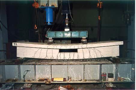
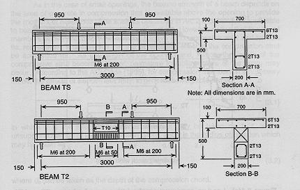
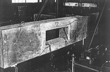
11 TS T2 Page 11


12 Page 12
13 DESIGN TOOLS National " Finite element analysis: elastic stress state area stress concentration " Truss analysis (Strut-and-tie model): lower bound approach detailing for crack control and strength Page 13 " Tests: specific cases serviceability & strength aspects

14 BEHAVIOUR BEAMS WITH LARGE OPENINGS Page 14

15 Principal tension stress contours Page 15

16 M t +M b + Nz = M = M N t + N b = 0 V t + V b = V Page 16

17 Inadequately reinforced openings Page 17


18 1 actual 2 idealised Page 18

19 Page 19

20 Page 20


21 Page 21

22 Page 22

23 Page 23

24 Shear carried by chords Page 24

25 Contraflexural points Page 25
26 Page 26 DESIGN & DETAILING OPENINGS - General guidelines sufficient area to develop ultimate compression block in flexure openings to be located more than D/2 from supports, concentrated loads and adjacent openings opening depth D/2 opening length stability chord member deflection requirement beam

27 Page 27
28 " Crack control National principal tensile stress direction stress concentration congestion reinforcement Page 28

29 2 Page 29 shear concentration factor 2 (i.e. 2V u ) diagonal bars to carry 50~75% total shear; vertical stirrups to carry the rest
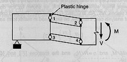
30 " Strength requirement 2 general approaches: mechanism approach failure at an opening is due to the formation four plastic hinges, one at each corner the opening truss model approach plasticity truss method strut-and-tie method applied loads are transferred across opening to supports by a truss system lower bound approaches Page 30
31 Mechanism Approach " Rigorous method 1. Calculate M u and V u at centre opening. 2. Assume suitable reinft. for chord members. Page 31
32 3. Determine N u in chord members and hinge moments (M u ) *,* from N u = [M u -(M s ) t -(M s ) b ]/z Slide 15 where (M s ) t = [(M u ) t,1 +(M u ) t,2 ]/2 (M s ) b = [(M u ) b,4 +(M u ) b,3 ]/2 and (M u ) *,* are related to N u by the respective M-N interaction diagrams. Page 32

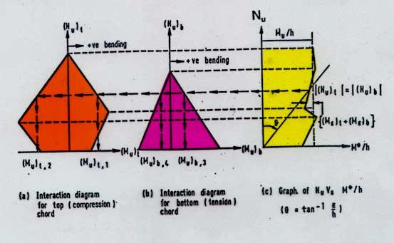
33 Page 33
34 4. Calculate V u in chord members from (V u ) t = [(M u ) t,2 -(M u ) t,1 ]/l (V u ) b = [(M u ) b,4 -(M u ) b,3 ]/l where l is the opening length. 5. Check that (V u ) t +(V u ) b V u. Page 34
35 " Simplified method National Unknowns: N t, N b, M t, M b, V t, V b 3 equations: M t +M b + Nz = M N t + N b = 0 V t + V b = V Assume M t = 0 M b = 0 V b =kv t where k = 0 Page 35 or k = A b /A t k = I b /I t

36 EXAMPLE A simply supported reinforced concrete beam, 300 mm wide and 600 mm deep, contains a rectangular opening and is subjected to a series point loads as shown. Design and detail the reinforcement for the opening if the design ultimate load P u is 52.8 kn. Material properties are: f c =30 MPa, f yv =250 MPa, and f y =460 MPa. Page 36
37 Solution by Mechanism Approach National Assume point contraflexure at midpoint chord members and that 40% shear is carried by bottom chord member. At centre opening, M u = knm V u = 79.2 kn Page 37
38 1. Bottom chord member (N u ) b = M u /z = kn (V u ) b = 0.4 V u = 31.7 kn (M u ) b =(V u ) b l/2 = 15.1 knm 2A s = 1954 mm 2 (3T20 top + 4T20 bottom) A sv /s = 400 mm 2 /m (minimum) 100 mm spacing) Page 38
39 2. Top chord member (N u ) t =408.6 kn; (V u ) t =47.5 kn; (M u ) t =22.6 knm 2A s = 516 mm 2 (2T12 +1T10 top & bottom) A sv /s = 525 mm 2 /m 100 mm spacing) Page 39

40 2T12 + 1T10 2T12 + 1T10 3T20 Page 40
 A s A s")
41 Truss Model Approaches National " Plasticity truss (AIJ approach) A s A s Page 41
42 " Shear capacity National V u = 2 bd vs ρ v f yv cot φ s where cot φ s = (νf c /ρ v f yv - 1) 2 νf c /ρ v f yv 1 ρ v = A v f yv /bs ν = f c /200 " Longitudinal reinforcement Page 42 T sn = A sn f y = V u l/2d vs T sf = A sf f y = V u (l +d vs cot φ s )/2d vs

43 Page 43 V d = A sd f yd sin θ d
44 Solution by Plasticity Truss Method (AIJ) National 1. Calculate v. v = V u /(2bd vs νf c )= Determine shear reinforcement. From v = ψ(1-ψ), obtain ψ ρ v f yv /νf c = ρ v = < ρ v,min = 1/3f y = 0.01 A sv /s = 400 mm 2 /m 100 mm spacing) Page 44
45 3. Determine longitudinal reinforcement. A sn = V u l/2f y d vs = 957 mm 2 A sf = V u (l +d vs cot φ s )/2f y d vs = 1080 mm 2 3T20 (near) + 4T20 (far) 4T20 3T20 3T20 4T20 Page 45
46 " Strut-and-tie method General Principles 1. Idealize structure as comprising concrete struts and reinforcement ties, joined at nodes. follow stress path given by elastic theory; refine as necessary equilibrium strut and tie forces deformation capacity concrete angle between struts and ties Page 46
47 2. Calculate forces in struts and ties from equilibrium. check stresses in struts (< 0.6f cd ) detail reinforcement according to calculated tie forces " check for anchorage reinforcement Page 47

48 Solution by Strut-and-Tie Method 1. Postulate strut-and-tie model. Page 48

49 2. Calculate member forces. Top chord takes 91% total shear. Stirrup force 3.3 times shear (Model may be simplified.) Page 49
50 3. Longitudinal reinforcement. Top chord Top steel: 1298 mm 2 (4T20) Bot. steel: 1741 mm 2 (4T25) Bottom chord Top steel: 171 mm 2 (2T12) Bot. steel: 590 mm 2 (2T20) Page 50
 Bottom chord A")
51 4. Transverse reinforcement. National Top chord A sv /s= 1567 mm 2 /m 65 mm) Bottom chord A sv /s= 284 mm 2 /m 65 mm) Page 51

52 Page 52
53 CALCULATION OF DEFLECTIONS Stirrup I t Rigid Abutment d s M- M V Hinges V M+ M I b d P l / 2 / 2 e l e P A/P Tan K H, 53
54 δ δ V Relative displacement hinge w.r.t. one end opening due to V (I t based on gross concrete section; I b based on a fully cracked section) δ = V 3 E c l e 2 I t 3 ( + ) I b Relative displacement one end opening w.r.t. the other end δ v = 2 δ = 12 E V c ( + ) I l t 3 e I b Midspan deflection beam δ = δ w + ( ) ( )... δ v + δ + opening1 v opening 2 A/P Tan K H, 54
55 Calculate the midspan service load deflection the beam described in the Example. SOLUTION Service load, P s = P u / 1.7 = 52.8 / 1.7 = 31.1 kn; V = 1.5 P s = 46.6 kn. Effective length chord members, l e = ( ) = 1000 mm. Assume I t = I g = 300 x /12 = 146 x 10 6 mm 4 ; I b = 0.1 x 146 x 10 6 mm 4 15 x 10 6 mm 4 Also, E c = = 26 x 10 3 MPa Hence, δ v = V l e3 / [12 E c ( I t + I b )] = 46.6 x / [12 x 26 x ( ) x 10 9 ] = 0.93 mm A/P Tan K H, 55
56 Midspan deflection, δ w, the beam is 11PL 3 /144E c I, where I can be conservatively estimated as the moment inertia the beam at a section through the opening. That is, I = 2 x [300 x / x 180 x ] = 5054 x 10 6 mm 4 As the span L is 6 m, therefore, δ w =11x 31.1 x 10 3 x (6000) 3 / [144 x 26 x 5054 x 10 9 ] = 3.91 mm Hence, the total midspan deflection is calculated as δ = δ v + δ w = = 4.84 mm < L/360 = 16.7 mm A/P Tan K H, 56

57 Summary National Deflection Add deflection due to shear at each opening Page 57
Lecture-04 Design of RC Members for Shear and Torsion
 Lecture-04 Design of RC Members for Shear and Torsion By: Prof. Dr. Qaisar Ali Civil Engineering Department UET Peshawar drqaisarali@uetpeshawar.edu.pk www.drqaisarali.com 1 Topics Addressed Design of
Department of Mechanics, Materials and Structures English courses Reinforced Concrete Structures Code: BMEEPSTK601. Lecture no. 6: SHEAR AND TORSION
 Budapest University of Technology and Economics Department of Mechanics, Materials and Structures English courses Reinforced Concrete Structures Code: BMEEPSTK601 Lecture no. 6: SHEAR AND TORSION Reinforced
- Rectangular Beam Design -
 Semester 1 2016/2017 - Rectangular Beam Design - Department of Structures and Material Engineering Faculty of Civil and Environmental Engineering University Tun Hussein Onn Malaysia Introduction The purposes
Design of reinforced concrete sections according to EN and EN
 Design of reinforced concrete sections according to EN 1992-1-1 and EN 1992-2 Validation Examples Brno, 21.10.2010 IDEA RS s.r.o. South Moravian Innovation Centre, U Vodarny 2a, 616 00 BRNO tel.: +420-511
twenty one concrete construction: shear & deflection ARCHITECTURAL STRUCTURES: FORM, BEHAVIOR, AND DESIGN DR. ANNE NICHOLS SUMMER 2014 lecture
 ARCHITECTURAL STRUCTURES: FORM, BEHAVIOR, AND DESIGN DR. ANNE NICHOLS SUMMER 2014 lecture twenty one concrete construction: Copyright Kirk Martini shear & deflection Concrete Shear 1 Shear in Concrete
Bending and Shear in Beams
 Bending and Shear in Beams Lecture 3 5 th October 017 Contents Lecture 3 What reinforcement is needed to resist M Ed? Bending/ Flexure Section analysis, singly and doubly reinforced Tension reinforcement,
PLATE GIRDERS II. Load. Web plate Welds A Longitudinal elevation. Fig. 1 A typical Plate Girder
 16 PLATE GIRDERS II 1.0 INTRODUCTION This chapter describes the current practice for the design of plate girders adopting meaningful simplifications of the equations derived in the chapter on Plate Girders
10/14/2011. Types of Shear Failure. CASE 1: a v /d 6. a v. CASE 2: 2 a v /d 6. CASE 3: a v /d 2
 V V Types o Shear Failure a v CASE 1: a v /d 6 d V a v CASE 2: 2 a v /d 6 d V a v CASE 3: a v /d 2 d V 1 Shear Resistance Concrete compression d V cz = Shear orce in the compression zone (20 40%) V a =
Design of Reinforced Concrete Beam for Shear
 Lecture 06 Design of Reinforced Concrete Beam for Shear By: Prof Dr. Qaisar Ali Civil Engineering Department UET Peshawar drqaisarali@uetpeshawar.edu.pk 1 Topics Addressed Shear Stresses in Rectangular
Design of AAC wall panel according to EN 12602
 Design of wall panel according to EN 160 Example 3: Wall panel with wind load 1.1 Issue Design of a wall panel at an industrial building Materials with a compressive strength 3,5, density class 500, welded
SERVICEABILITY LIMIT STATE DESIGN
 CHAPTER 11 SERVICEABILITY LIMIT STATE DESIGN Article 49. Cracking Limit State 49.1 General considerations In the case of verifications relating to Cracking Limit State, the effects of actions comprise
Design of Reinforced Concrete Beam for Shear
 Lecture 06 Design of Reinforced Concrete Beam for Shear By: Civil Engineering Department UET Peshawar drqaisarali@uetpeshawar.edu.pk Topics Addressed Shear Stresses in Rectangular Beams Diagonal Tension
Practical Design to Eurocode 2
 Practical Design to Eurocode 2 The webinar will start at 12.30 (Any questions beforehand? use Questions on the GoTo Control Panel) Course Outline Lecture Date Speaker Title 1 21 Sep Jenny Burridge Introduction,
DESIGN AND DETAILING OF COUNTERFORT RETAINING WALL
 DESIGN AND DETAILING OF COUNTERFORT RETAINING WALL When the height of the retaining wall exceeds about 6 m, the thickness of the stem and heel slab works out to be sufficiently large and the design becomes
Plastic design of continuous beams
 Budapest University of Technology and Economics Department of Mechanics, Materials and Structures English courses Reinforced Concrete Structures Code: BMEEPSTK601 Lecture no. 4: Plastic design of continuous
ε t increases from the compressioncontrolled Figure 9.15: Adjusted interaction diagram
 CHAPTER NINE COLUMNS 4 b. The modified axial strength in compression is reduced to account for accidental eccentricity. The magnitude of axial force evaluated in step (a) is multiplied by 0.80 in case
Seismic Pushover Analysis Using AASHTO Guide Specifications for LRFD Seismic Bridge Design
 Seismic Pushover Analysis Using AASHTO Guide Specifications for LRFD Seismic Bridge Design Elmer E. Marx, Alaska Department of Transportation and Public Facilities Michael Keever, California Department
Detailing. Lecture 9 16 th November Reinforced Concrete Detailing to Eurocode 2
 Detailing Lecture 9 16 th November 2017 Reinforced Concrete Detailing to Eurocode 2 EC2 Section 8 - Detailing of Reinforcement - General Rules Bar spacing, Minimum bend diameter Anchorage of reinforcement
DEFORMATION CAPACITY OF OLDER RC SHEAR WALLS: EXPERIMENTAL ASSESSMENT AND COMPARISON WITH EUROCODE 8 - PART 3 PROVISIONS
 DEFORMATION CAPACITY OF OLDER RC SHEAR WALLS: EXPERIMENTAL ASSESSMENT AND COMPARISON WITH EUROCODE 8 - PART 3 PROVISIONS Konstantinos CHRISTIDIS 1, Emmanouil VOUGIOUKAS 2 and Konstantinos TREZOS 3 ABSTRACT
Delhi Noida Bhopal Hyderabad Jaipur Lucknow Indore Pune Bhubaneswar Kolkata Patna Web: Ph:
 Serial : IG1_CE_G_Concrete Structures_100818 Delhi Noida Bhopal Hyderabad Jaipur Lucknow Indore Pune Bhubaneswar Kolkata Patna Web: E-mail: info@madeeasy.in Ph: 011-451461 CLASS TEST 018-19 CIVIL ENGINEERING
SHEAR DESIGN EQUATIONS FOR FRP RC BEAMS
 SHEAR DESIGN EQUATIONS FOR FRP RC BEAMS Dr. Maurizio Guadagnini Dr. Kypros Pilakoutas Professor Peter Waldron Centre for Dept. of Civil and Structural Engineering The University of Sheffield, UK Outline
Design of Beams (Unit - 8)
") Design of Beams (Unit - 8) Contents Introduction Beam types Lateral stability of beams Factors affecting lateral stability Behaviour of simple and built - up beams in bending (Without vertical stiffeners)
Design of Beams (Unit - 8) Contents Introduction Beam types Lateral stability of beams Factors affecting lateral stability Behaviour of simple and built - up beams in bending (Without vertical stiffeners)
PURE BENDING. If a simply supported beam carries two point loads of 10 kn as shown in the following figure, pure bending occurs at segment BC.
 BENDING STRESS The effect of a bending moment applied to a cross-section of a beam is to induce a state of stress across that section. These stresses are known as bending stresses and they act normally
Chapter 8. Shear and Diagonal Tension
 Chapter 8. and Diagonal Tension 8.1. READING ASSIGNMENT Text Chapter 4; Sections 4.1-4.5 Code Chapter 11; Sections 11.1.1, 11.3, 11.5.1, 11.5.3, 11.5.4, 11.5.5.1, and 11.5.6 8.2. INTRODUCTION OF SHEAR
Reinforced Concrete Structures
 Reinforced Concrete Structures MIM 232E Dr. Haluk Sesigür I.T.U. Faculty of Architecture Structural and Earthquake Engineering WG Ultimate Strength Theory Design of Singly Reinforced Rectangular Beams
ME Final Exam. PROBLEM NO. 4 Part A (2 points max.) M (x) y. z (neutral axis) beam cross-sec+on. 20 kip ft. 0.2 ft. 10 ft. 0.1 ft.
 M (x) y. z (neutral axis) beam cross-sec+on. 20 kip ft. 0.2 ft. 10 ft. 0.1 ft.") ME 323 - Final Exam Name December 15, 2015 Instructor (circle) PROEM NO. 4 Part A (2 points max.) Krousgrill 11:30AM-12:20PM Ghosh 2:30-3:20PM Gonzalez 12:30-1:20PM Zhao 4:30-5:20PM M (x) y 20 kip ft 0.2
ME 323 - Final Exam Name December 15, 2015 Instructor (circle) PROEM NO. 4 Part A (2 points max.) Krousgrill 11:30AM-12:20PM Ghosh 2:30-3:20PM Gonzalez 12:30-1:20PM Zhao 4:30-5:20PM M (x) y 20 kip ft 0.2
INFLUENCE OF FLANGE STIFFNESS ON DUCTILITY BEHAVIOUR OF PLATE GIRDER
 International Journal of Civil Structural 6 Environmental And Infrastructure Engineering Research Vol.1, Issue.1 (2011) 1-15 TJPRC Pvt. Ltd.,. INFLUENCE OF FLANGE STIFFNESS ON DUCTILITY BEHAVIOUR OF PLATE
NAGY GYÖRGY Tamás Assoc. Prof, PhD
 NAGY GYÖRGY Tamás Assoc. Prof, PhD E mail: tamas.nagy gyorgy@upt.ro Tel: +40 256 403 935 Web: http://www.ct.upt.ro/users/tamasnagygyorgy/index.htm Office: A219 SIMPLE SUPORTED BEAM b = 15 cm h = 30 cm
STRUCTURAL ANALYSIS CHAPTER 2. Introduction
 CHAPTER 2 STRUCTURAL ANALYSIS Introduction The primary purpose of structural analysis is to establish the distribution of internal forces and moments over the whole part of a structure and to identify
UNIT-I STRESS, STRAIN. 1. A Member A B C D is subjected to loading as shown in fig determine the total elongation. Take E= 2 x10 5 N/mm 2
 UNIT-I STRESS, STRAIN 1. A Member A B C D is subjected to loading as shown in fig determine the total elongation. Take E= 2 x10 5 N/mm 2 Young s modulus E= 2 x10 5 N/mm 2 Area1=900mm 2 Area2=400mm 2 Area3=625mm
Standardisation of UHPC in Germany
 Standardisation of UHPC in Germany Part II: Development of Design Rules, University of Siegen Prof. Dr.-Ing. Ekkehard Fehling, University of Kassel 1 Overvie Introduction: Work of the Task Group Design
Job No. Sheet No. Rev. CONSULTING Engineering Calculation Sheet. Member Design - Reinforced Concrete Beam BS8110 v Member Design - RC Beam XX
 CONSULTING Engineering Calculation Sheet E N G I N E E R S Consulting Engineers jxxx 1 Effects From Structural Analysis Design axial force, F (tension -ve and compression +ve) (ensure < 0.1f cu b w h 0
ULTIMATE SHEAR OF BEAMS STRENGTHENED WITH CFRP SHEETS
 ULTIMATE SHEAR OF BEAMS STRENGTHENED WITH CFRP SHEETS U. Ianniruberto and M. Imbimbo Department of Civil Engineering, University of Rome Tor Vergata Via di Tor Vergata 0, 0033, Rome, Italy SUMMARY: The
Earthquake-resistant design of indeterminate reinforced-concrete slender column elements
 Engineering Structures 29 (2007) 163 175 www.elsevier.com/locate/engstruct Earthquake-resistant design of indeterminate reinforced-concrete slender column elements Gerasimos M. Kotsovos a, Christos Zeris
SeismoBuild Verification Report (KANEPE) For version 2018
 For version 2018") SeismoBuild Verification Report (KANEPE) For version 2018 Copyright Copyright 2002-2018 Seismosoft Ltd. All rights reserved. SeismoBuild is a registered trademark of Seismosoft Ltd. Copyright law protects
SeismoBuild Verification Report (KANEPE) For version 2018 Copyright Copyright 2002-2018 Seismosoft Ltd. All rights reserved. SeismoBuild is a registered trademark of Seismosoft Ltd. Copyright law protects
Shear Strength of Slender Reinforced Concrete Beams without Web Reinforcement
 RESEARCH ARTICLE OPEN ACCESS Shear Strength of Slender Reinforced Concrete Beams without Web Reinforcement Prof. R.S. Chavan*, Dr. P.M. Pawar ** (Department of Civil Engineering, Solapur University, Solapur)
NUMERICAL SIMULATIONS OF CORNERS IN RC FRAMES USING STRUT-AND-TIE METHOD AND CDP MODEL
 Numerical simulations of corners in RC frames using Strut-and-Tie Method and CDP model XIII International Conference on Computational Plasticity. Fundamentals and Applications COMPLAS XIII E. Oñate, D.R.J.
QUESTION BANK SEMESTER: III SUBJECT NAME: MECHANICS OF SOLIDS
 QUESTION BANK SEMESTER: III SUBJECT NAME: MECHANICS OF SOLIDS UNIT 1- STRESS AND STRAIN PART A (2 Marks) 1. Define longitudinal strain and lateral strain. 2. State Hooke s law. 3. Define modular ratio,
QUESTION BANK DEPARTMENT: CIVIL SEMESTER: III SUBJECT CODE: CE2201 SUBJECT NAME: MECHANICS OF SOLIDS UNIT 1- STRESS AND STRAIN PART A
 DEPARTMENT: CIVIL SUBJECT CODE: CE2201 QUESTION BANK SEMESTER: III SUBJECT NAME: MECHANICS OF SOLIDS UNIT 1- STRESS AND STRAIN PART A (2 Marks) 1. Define longitudinal strain and lateral strain. 2. State
POST-PEAK BEHAVIOR OF FRP-JACKETED REINFORCED CONCRETE COLUMNS
 POST-PEAK BEHAVIOR OF FRP-JACKETED REINFORCED CONCRETE COLUMNS - Technical Paper - Tidarut JIRAWATTANASOMKUL *1, Dawei ZHANG *2 and Tamon UEDA *3 ABSTRACT The objective of this study is to propose a new
SEISMIC PERFORMANCE OF CONCRETE COLUMNS WITH INADEQUATE TRANSVERSE REINFORCEMENT. Alistair Boys 1 Des K. Bull 2 Stefano Pampanin 3 ABSTRACT
 SEISMIC PERFORMANCE OF CONCRETE COLUMNS WITH INADEQUATE TRANSVERSE REINFORCEMENT. Alistair Boys 1 Des K. Bull 2 Stefano Pampanin 3 ABSTRACT Existing New Zealand building stock contains a significant number
Civil Engineering Design (1) Design of Reinforced Concrete Columns 2006/7
 Design of Reinforced Concrete Columns 2006/7") Civil Engineering Design (1) Design of Reinforced Concrete Columns 2006/7 Dr. Colin Caprani, Chartered Engineer 1 Contents 1. Introduction... 3 1.1 Background... 3 1.2 Failure Modes... 5 1.3 Design Aspects...
Civil Engineering Design (1) Design of Reinforced Concrete Columns 2006/7 Dr. Colin Caprani, Chartered Engineer 1 Contents 1. Introduction... 3 1.1 Background... 3 1.2 Failure Modes... 5 1.3 Design Aspects...
Lap splice length and details of column longitudinal reinforcement at plastic hinge region
 Lap length and details of column longitudinal reinforcement at plastic hinge region Hong-Gun Park 1) and Chul-Goo Kim 2) 1), 2 Department of Architecture and Architectural Engineering, Seoul National University,
Entrance exam Master Course
 - 1 - Guidelines for completion of test: On each page, fill in your name and your application code Each question has four answers while only one answer is correct. o Marked correct answer means 4 points
3.2 Reinforced Concrete Slabs Slabs are divided into suspended slabs. Suspended slabs may be divided into two groups:
 Sabah Shawkat Cabinet of Structural Engineering 017 3. Reinforced Concrete Slabs Slabs are divided into suspended slabs. Suspended slabs may be divided into two groups: (1) slabs supported on edges of
Lecture 15 Strain and stress in beams
 Spring, 2019 ME 323 Mechanics of Materials Lecture 15 Strain and stress in beams Reading assignment: 6.1 6.2 News: Instructor: Prof. Marcial Gonzalez Last modified: 1/6/19 9:42:38 PM Beam theory (@ ME
CHAPTER 4. ANALYSIS AND DESIGN OF COLUMNS
 4.1. INTRODUCTION CHAPTER 4. ANALYSIS AND DESIGN OF COLUMNS A column is a vertical structural member transmitting axial compression loads with or without moments. The cross sectional dimensions of a column
Sabah Shawkat Cabinet of Structural Engineering Walls carrying vertical loads should be designed as columns. Basically walls are designed in
 Sabah Shawkat Cabinet of Structural Engineering 17 3.6 Shear walls Walls carrying vertical loads should be designed as columns. Basically walls are designed in the same manner as columns, but there are
CIVIL DEPARTMENT MECHANICS OF STRUCTURES- ASSIGNMENT NO 1. Brach: CE YEAR:
 MECHANICS OF STRUCTURES- ASSIGNMENT NO 1 SEMESTER: V 1) Find the least moment of Inertia about the centroidal axes X-X and Y-Y of an unequal angle section 125 mm 75 mm 10 mm as shown in figure 2) Determine
CHAPTER 6: ULTIMATE LIMIT STATE
 CHAPTER 6: ULTIMATE LIMIT STATE 6.1 GENERAL It shall be in accordance with JSCE Standard Specification (Design), 6.1. The collapse mechanism in statically indeterminate structures shall not be considered.
Therefore, for all members designed according to ACI 318 Code, f s =f y at failure, and the nominal strength is given by:
 5.11. Under-reinforced Beams (Read Sect. 3.4b oour text) We want the reinforced concrete beams to fail in tension because is not a sudden failure. Therefore, following Figure 5.3, you have to make sure
9.5 Compression Members
 9.5 Compression Members This section covers the following topics. Introduction Analysis Development of Interaction Diagram Effect of Prestressing Force 9.5.1 Introduction Prestressing is meaningful when
STRENGTH OF MATERIALS-I. Unit-1. Simple stresses and strains
 STRENGTH OF MATERIALS-I Unit-1 Simple stresses and strains 1. What is the Principle of surveying 2. Define Magnetic, True & Arbitrary Meridians. 3. Mention different types of chains 4. Differentiate between
Civil Engineering Design (1) Analysis and Design of Slabs 2006/7
 Analysis and Design of Slabs 2006/7") Civil Engineering Design (1) Analysis and Design of Slabs 006/7 Dr. Colin Caprani, Chartered Engineer 1 Contents 1. Elastic Methods... 3 1.1 Introduction... 3 1. Grillage Analysis... 4 1.3 Finite Element
Civil Engineering Design (1) Analysis and Design of Slabs 006/7 Dr. Colin Caprani, Chartered Engineer 1 Contents 1. Elastic Methods... 3 1.1 Introduction... 3 1. Grillage Analysis... 4 1.3 Finite Element
Chapter 4. Test results and discussion. 4.1 Introduction to Experimental Results
 Chapter 4 Test results and discussion This chapter presents a discussion of the results obtained from eighteen beam specimens tested at the Structural Technology Laboratory of the Technical University
Chapter. Materials. 1.1 Notations Used in This Chapter
 Chapter 1 Materials 1.1 Notations Used in This Chapter A Area of concrete cross-section C s Constant depending on the type of curing C t Creep coefficient (C t = ε sp /ε i ) C u Ultimate creep coefficient
INFLUENCE OF LOADING RATIO ON QUANTIFIED VISIBLE DAMAGES OF R/C STRUCTURAL MEMBERS
 Paper N 1458 Registration Code: S-H1463506048 INFLUENCE OF LOADING RATIO ON QUANTIFIED VISIBLE DAMAGES OF R/C STRUCTURAL MEMBERS N. Takahashi (1) (1) Associate Professor, Tohoku University, ntaka@archi.tohoku.ac.jp
Eurocode Training EN : Reinforced Concrete
 Eurocode Training EN 1992-1-1: Reinforced Concrete Eurocode Training EN 1992-1-1 All information in this document is subject to modification without prior notice. No part of this manual may be reproduced,
SERVICEABILITY OF BEAMS AND ONE-WAY SLABS
 CHAPTER REINFORCED CONCRETE Reinforced Concrete Design A Fundamental Approach - Fifth Edition Fifth Edition SERVICEABILITY OF BEAMS AND ONE-WAY SLABS A. J. Clark School of Engineering Department of Civil
JUT!SI I I I TO BE RETURNED AT THE END OF EXAMINATION. THIS PAPER MUST NOT BE REMOVED FROM THE EXAM CENTRE. SURNAME: FIRST NAME: STUDENT NUMBER:
 JUT!SI I I I TO BE RETURNED AT THE END OF EXAMINATION. THIS PAPER MUST NOT BE REMOVED FROM THE EXAM CENTRE. SURNAME: FIRST NAME: STUDENT NUMBER: COURSE: Tutor's name: Tutorial class day & time: SPRING
Appendix K Design Examples
 Appendix K Design Examples Example 1 * Two-Span I-Girder Bridge Continuous for Live Loads AASHTO Type IV I girder Zero Skew (a) Bridge Deck The bridge deck reinforcement using A615 rebars is shown below.
Design of a Multi-Storied RC Building
 Design of a Multi-Storied RC Building 16 14 14 3 C 1 B 1 C 2 B 2 C 3 B 3 C 4 13 B 15 (S 1 ) B 16 (S 2 ) B 17 (S 3 ) B 18 7 B 4 B 5 B 6 B 7 C 5 C 6 C 7 C 8 C 9 7 B 20 B 22 14 B 19 (S 4 ) C 10 C 11 B 23
DIAGONAL TENSION RC BEAM without SHEAR REINFORCEMENT RC BEAM with WEB REINFORCEMENT KCI CODE PROVISION. ALTERNATIVE MODELS for SHEAR ANALYSIS
 DIAGONAL TENSION RC BEAM without SHEAR REINFORCEMENT RC BEAM with WEB REINFORCEMENT KCI CODE PROVISION DEEP BEAMS ALTERNATIVE MODELS for SHEAR ANALYSIS SHEAR FRICTION DESIGN METHOD &DESIGN 447.327 Theory
Displacement-based methods EDCE: Civil and Environmental Engineering CIVIL Advanced Earthquake Engineering
 Displacement-based methods EDCE: Civil and Environmental Engineering CIVIL 706 - Advanced Earthquake Engineering EDCE-EPFL-ENAC-SGC 2016-1- Content! Link to force-based methods! Assumptions! Reinforced
EUROCODE EN SEISMIC DESIGN OF BRIDGES
 Brussels, 18-20 February 2008 Dissemination of information workshop 1 EUROCODE EN1998-2 SEISMIC DESIGN OF BRIDGES Basil Kolias Basic Requirements Brussels, 18-20 February 2008 Dissemination of information
Evaluation of size effect on shear strength of reinforced concrete deep beams using refined strut-and-tie model
 Sādhanā Vol. 7, Part, February, pp. 89 5. c Indian Academy of Sciences Evaluation of size effect on shear strength of reinforced concrete deep beams using refined strut-and-tie model GAPPARAO and R SUNDARESAN
Basic Energy Principles in Stiffness Analysis
 Basic Energy Principles in Stiffness Analysis Stress-Strain Relations The application of any theory requires knowledge of the physical properties of the material(s) comprising the structure. We are limiting
FINITE ELEMENT ANALYSIS OF TAPERED COMPOSITE PLATE GIRDER WITH A NON-LINEAR VARYING WEB DEPTH
 Journal of Engineering Science and Technology Vol. 12, No. 11 (2017) 2839-2854 School of Engineering, Taylor s University FINITE ELEMENT ANALYSIS OF TAPERED COMPOSITE PLATE GIRDER WITH A NON-LINEAR VARYING
National Exams May 2015
 National Exams May 2015 04-BS-6: Mechanics of Materials 3 hours duration Notes: If doubt exists as to the interpretation of any question, the candidate is urged to submit with the answer paper a clear
D : SOLID MECHANICS. Q. 1 Q. 9 carry one mark each. Q.1 Find the force (in kn) in the member BH of the truss shown.
 in the member BH of the truss shown.") D : SOLID MECHANICS Q. 1 Q. 9 carry one mark each. Q.1 Find the force (in kn) in the member BH of the truss shown. Q.2 Consider the forces of magnitude F acting on the sides of the regular hexagon having
D : SOLID MECHANICS Q. 1 Q. 9 carry one mark each. Q.1 Find the force (in kn) in the member BH of the truss shown. Q.2 Consider the forces of magnitude F acting on the sides of the regular hexagon having
 UNIT III DEFLECTION OF BEAMS 1. What are the methods for finding out the slope and deflection at a section? The important methods used for finding out the slope and deflection at a section in a loaded
Module 6. Approximate Methods for Indeterminate Structural Analysis. Version 2 CE IIT, Kharagpur
 Module 6 Approximate Methods for Indeterminate Structural Analysis Lesson 35 Indeterminate Trusses and Industrial rames Instructional Objectives: After reading this chapter the student will be able to
3 Hours/100 Marks Seat No.
 *17304* 17304 14115 3 Hours/100 Marks Seat No. Instructions : (1) All questions are compulsory. (2) Illustrate your answers with neat sketches wherever necessary. (3) Figures to the right indicate full
Chapter 5 Structural Elements: The truss & beam elements
 Institute of Structural Engineering Page 1 Chapter 5 Structural Elements: The truss & beam elements Institute of Structural Engineering Page 2 Chapter Goals Learn how to formulate the Finite Element Equations
APPLICATION OF INTENSIVE SHEAR REINFORCEMENT TO SPLICING SLEEVE JOINT OF PRE-FABRICATED REINFORCEMENT ASSEMBLY
 13 th World Conference on Earthquake Engineering Vancouver, B.C., Canada August 1-6, 24 Paper No. 587 APPLICATION OF INTENSIVE SHEAR REINFORCEMENT TO SPLICING SLEEVE JOINT OF PRE-FABRICATED REINFORCEMENT
EFFECT OF SHEAR REINFORCEMENT ON FAILURE MODE OF RC BRIDGE PIERS SUBJECTED TO STRONG EARTHQUAKE MOTIONS
 EFFECT OF SHEAR REINFORCEMENT ON FAILURE MODE OF RC BRIDGE PIERS SUBJECTED TO STRONG EARTHQUAKE MOTIONS Atsuhiko MACHIDA And Khairy H ABDELKAREEM SUMMARY Nonlinear D FEM was utilized to carry out inelastic
Fracture Mechanics of Non-Shear Reinforced R/C Beams
 Irina Kerelezova Thomas Hansen M. P. Nielsen Fracture Mechanics of Non-Shear Reinforced R/C Beams DANMARKS TEKNISKE UNIVERSITET Report BYG DTU R-154 27 ISSN 161-2917 ISBN 97887-7877-226-5 Fracture Mechanics
Failure interaction curves for combined loading involving torsion, bending, and axial loading
 Failure interaction curves for combined loading involving torsion, bending, and axial loading W M Onsongo Many modern concrete structures such as elevated guideways are subjected to combined bending, torsion,
Name :. Roll No. :... Invigilator s Signature :.. CS/B.TECH (CE-NEW)/SEM-3/CE-301/ SOLID MECHANICS
/SEM-3/CE-301/ SOLID MECHANICS") Name :. Roll No. :..... Invigilator s Signature :.. 2011 SOLID MECHANICS Time Allotted : 3 Hours Full Marks : 70 The figures in the margin indicate full marks. Candidates are required to give their answers
Name :. Roll No. :..... Invigilator s Signature :.. 2011 SOLID MECHANICS Time Allotted : 3 Hours Full Marks : 70 The figures in the margin indicate full marks. Candidates are required to give their answers
Generation of Biaxial Interaction Surfaces
 COPUTERS AND STRUCTURES, INC., BERKELEY, CALIFORNIA AUGUST 2002 CONCRETE FRAE DESIGN BS 8110-97 Technical Note This Technical Note describes how the program checks column capacity or designs reinforced
CRACK FORMATION AND CRACK PROPAGATION INTO THE COMPRESSION ZONE ON REINFORCED CONCRETE BEAM STRUCTURES
 S. Kakay et al. Int. J. Comp. Meth. and Exp. Meas. Vol. 5 No. (017) 116 14 CRACK FORMATION AND CRACK PROPAGATION INTO THE COMPRESSION ZONE ON REINFORCED CONCRETE BEAM STRUCTURES SAMDAR KAKAY DANIEL BÅRDSEN
Prediction of static response of Laced Steel-Concrete Composite beam using effective moment of inertia approach
 Prediction of static response of Laced Steel-Concrete Composite beam using effective moment of inertia approach Thirumalaiselvi A 1, 2, Anandavalli N 1,2, Rajasankar J 1,2, Nagesh R. Iyer 2 1 Academy of
Mechanics of Structure
 S.Y. Diploma : Sem. III [CE/CS/CR/CV] Mechanics of Structure Time: Hrs.] Prelim Question Paper Solution [Marks : 70 Q.1(a) Attempt any SIX of the following. [1] Q.1(a) Define moment of Inertia. State MI
Supplement: Statically Indeterminate Trusses and Frames
 : Statically Indeterminate Trusses and Frames Approximate Analysis - In this supplement, we consider an approximate method of solving statically indeterminate trusses and frames subjected to lateral loads
2. Determine the deflection at C of the beam given in fig below. Use principal of virtual work. W L/2 B A L C
 CE-1259, Strength of Materials UNIT I STRESS, STRAIN DEFORMATION OF SOLIDS Part -A 1. Define strain energy density. 2. State Maxwell s reciprocal theorem. 3. Define proof resilience. 4. State Castigliano
Samantha Ramirez, MSE
 Samantha Ramirez, MSE Centroids The centroid of an area refers to the point that defines the geometric center for the area. In cases where the area has an axis of symmetry, the centroid will lie along
FCP Short Course. Ductile and Brittle Fracture. Stephen D. Downing. Mechanical Science and Engineering
 FCP Short Course Ductile and Brittle Fracture Stephen D. Downing Mechanical Science and Engineering 001-015 University of Illinois Board of Trustees, All Rights Reserved Agenda Limit theorems Plane Stress
CHAPTER 4: BENDING OF BEAMS
 (74) CHAPTER 4: BENDING OF BEAMS This chapter will be devoted to the analysis of prismatic members subjected to equal and opposite couples M and M' acting in the same longitudinal plane. Such members are
Prediction of the Lateral Load Displacement Curves for RC Squat Walls Failing in Shear
 PESDES 2017 International Workshop on Performance-Based Seismic Design of Structures Prediction of the Lateral Load Displacement Curves for RC Squat Walls Failing in Shear Shyh-Jiann Hang Director National
Parametric analysis and torsion design charts for axially restrained RC beams
 Structural Engineering and Mechanics, Vol. 55, No. 1 (2015) 1-27 DOI: http://dx.doi.org/10.12989/sem.2015.55.1.001 1 Parametric analysis and torsion design charts for axially restrained RC beams Luís F.A.
Coupling Beams of Shear Walls
 Coupling Beams of Shear Walls Modelling Procedure for the Seismic Analysis of RC Structures João Miguel Damião Bezelga (1) July 215 (1) Instituto Superior Técnico Universidade de Lisboa, Av. Rovisco Pais,
Chord rotation demand for Effective Catenary Action under Monotonic. Loadings
 ICCM015, 14-17 th July, Auckland, NZ Chord rotation demand for Effective Catenary Action under Monotonic Loadings *Meng-Hao Tsai Department of Civil Engineering, National Pingtung University of Science
Crack Width Prediction for Interior Portion of Inverted 'T' Bent Caps
 Crack Width Prediction for Interior Portion of Inverted 'T' Bent Caps Prepared for Texas Department of Transportation By Rong-Hua Zhu Wirat Wanichakorn and Thomas T. C. Hsu Department of Civil and Environmental
SHEAR CAPACITY OF REINFORCED CONCRETE COLUMNS RETROFITTED WITH VERY FLEXIBLE FIBER REINFORCED POLYMER WITH VERY LOW YOUNG S MODULUS
 SHEAR CAPACITY OF REINFORCED CONCRETE COLUMNS RETROFITTED WITH VERY FLEXILE FIER REINFORCED POLYMER WITH VERY LOW YOUNG S MODULUS Hu Shaoqing Supervisor: Susumu KONO ** MEE8165 ASTRACT FRP with low Young
Chapter 2. Design for Shear. 2.1 Introduction. Neutral axis. Neutral axis. Fig. 4.1 Reinforced concrete beam in bending. By Richard W.
 Chapter 2 Design for Shear By Richard W. Furlong 2.1 Introduction Shear is the term assigned to forces that act perpendicular to the longitudinal axis of structural elements. Shear forces on beams are
Eurocode 8 Part 3: Assessment and retrofitting of buildings
 in the Euro-Mediterranean Area Eurocode 8 Part 3: Assessment and retrofitting of buildings Paolo Emilio Pinto Università di Roma La Sapienza Urgency of guidance documents for assessment and retrofit in
CAPACITY DESIGN FOR TALL BUILDINGS WITH MIXED SYSTEM
 13 th World Conference on Earthquake Engineering Vancouver, B.C., Canada August 1-6, 24 Paper No. 2367 CAPACITY DESIGN FOR TALL BUILDINGS WITH MIXED SYSTEM M.UMA MAHESHWARI 1 and A.R.SANTHAKUMAR 2 SUMMARY
DESIGN OF STAIRCASE. Dr. Izni Syahrizal bin Ibrahim. Faculty of Civil Engineering Universiti Teknologi Malaysia
 DESIGN OF STAIRCASE Dr. Izni Syahrizal bin Ibrahim Faculty of Civil Engineering Universiti Teknologi Malaysia Email: iznisyahrizal@utm.my Introduction T N T G N G R h Flight Span, L Landing T = Thread
MODELLING NON-LINEAR BEHAVIOUR OF STEEL FIBRE REINFORCED CONCRETE
 6th RILEM Symposium on Fibre-Reinforced Concretes (FRC) - BEFIB - September, Varenna, Italy MODELLING NON-LINEAR BEHAVIOUR OF STEEL FIBRE REINFORCED CONCRETE W. A. Elsaigh, J. M. Robberts and E.P. Kearsley
Applications of the Plate Membrane Theory
 Chapter 2 Applications of the Plate Membrane Theory In this chapter we will give solutions for plates, which are loaded only on their edges. This implies that no distributed forces p x and p y occur, and