Reinforced Concrete Structures
|
|
|
- Hope Hines
- 5 years ago
- Views:
Transcription


1 Reinforced Concrete Structures MIM 232E Dr. Haluk Sesigür I.T.U. Faculty of Architecture Structural and Earthquake Engineering WG Ultimate Strength Theory Design of Singly Reinforced Rectangular Beams RCSD-3

2 RC Beam Design Upper reinforcement Upper reinforcement stirrup lower reinforcement 2

3 RC Beam Design 3


4 Ultimate Strength Theory compression Moment couple tension 4
 compression tension compression compression force Concrete is good in compression; Tension Tension force compression crushing tension cracking")
5 Ultimate Strength Theory Pure bending load... Moment : couple (tension and comp. force) compression tension compression compression force Concrete is good in compression; Tension Tension force compression crushing tension cracking Reinforcment to resist tension at the bottom 5


6 Ultimate Strength Theory Necessity for reinforcement M V Deformation; cracking at tension region Cruching at compression region 6
 ε s = strain of steel (elongation) Horizontal equilibrium ; Fc=Fs Comp. N.A.")
7 Ultimate Strength Theory Deformation Moment couple As: area of tension reinf. Fs: tension force of steel Fc: compression force of concrete z: moment arm ε c = strain of concrete (shortening) ε s = strain of steel (elongation) Horizontal equilibrium ; Fc=Fs Comp. N.A. ε c = strain of concrete (shortening) ε s = strain of steel (elongation) Cross-setion tension İnternal forces crack deformation 7
8 Ultimate Strength Theory concrete Idealized Stress-Strain (σ-ε) Relationships steel fcd fyd =0.003 crushing e yd = fyd E s =0.01 rupture E s =210000MPa (modulus of elasticity) fcd = fck 1,5 fyd = fyk 1,15 8
9 Ultimate Strength Theory general Md moment copule (Fc;Fs) Fc=Fs Compression at top; tension at bottom Fc can be carried (f cd is good); Fs cannot be carried (f ctd is poor) cracking occur Fs should be complately carried by As (no concrete contribution is considered) ε c shortening at top; ε s elongation at bottom; by rotation of cross section 9
")


10 Ultimate Strength Theory Deformation & strain Moment (Md) increases crushing deformation İnternal forces deformation İnternal forces deformation İnternal forces deformation İnternal forces cracking Starin increases cracking cracking 10
 http://mmf2.ogu.edu.tr/atopcu/index.")
11 Ultimate Strength Theory compressive stress block Theoritical Stress distribution Virtual Stress distribution Fs Fs Neutral axis Theoric distribution (TS 500) 11

12 Ultimate Strength Theory compressive stress block beam beam Theoritical CEB model ACI TS5000 Stress distribution at the crushing/failure of concrete 12
13 Ultimate Strength Theory Assumptions (TS500) 1- Strain distribution is lineer (plane sections remain plane-bernoulli/navier) 2- Tensile strength of concrete is neglected ( ~0) 3- full adherence 4- Elasto-plastic curve Design strength (yielding) Strain at yielding Strain at rupture (ε su ) 13


14 Ultimate Strength Theory Assumptions (TS500) 5- at ultimate strength; ε c = ε cu = at ultimate strength; theoric σ c -ε c 7- shape of tensional region is not important Equivalent sections 14
15 Ultimate Strength Theory Assumptions (TS500) Failure/fracture types; ε c = ε cu = concrete crushing Mr is reached failure condition limit; At this point; there are 3 failure types due to yielding of reinforcement; Ductile failure (tensional) Brittle failure (compression) Failure at balance (brittle) 15
 Firstly bar yields; then ε c = ε cu and concrete crushes.")
 Design strength (yielding) Strain at yielding Strain at rupture (ε su ) Section deformation If ε s < ε")
16 Ultimate Strength Theory Assumptions (TS500) 1. Ductile failure (tensional) Before ε c = ε cu = ; reinforcing bar yields (ε s ε sd ) Firstly bar yields; then ε c = ε cu and concrete crushes. Ductile Failure Section deformation 2. Brittle failure (compression) Design strength (yielding) Strain at yielding Strain at rupture (ε su ) Section deformation If ε s < ε sd (before yielding) ; ε c becomes ε cu = ; brittle failure occurs. Firstly concrete cruches, bar does not yield. 16

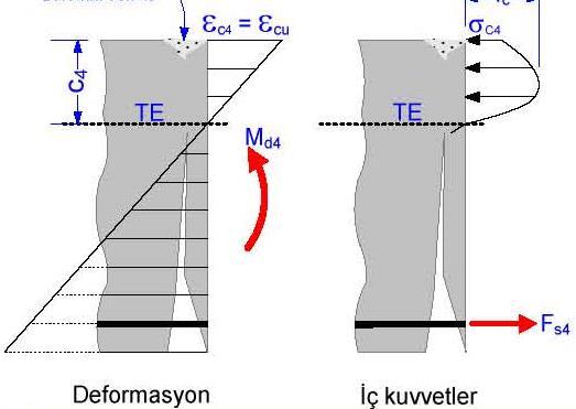
17 Ultimate Strength Theory Assumptions (TS500) 3. Failure at balance (brittle) It is a special case. Section deformation When ε s = ε sd ; ε c = ε cu = Concrete cruching and yielding of bar are in the same time No more elongation is available in Reinf. Bar. Brittle failure 17
18 Pure bending General d h concrete reinforcement b f ck ε co ε cu ε c T Pure bending region f yk steel M 18
19 Pure bending Stress-strain / cases ε c < ε c0 ε c < ε c0 ε c = ε c0 ε c = ε cu ε c < ε c0 ε s < ε y ε s = ε y ε s > ε y ε s < ε y ε s = ε u σ c < f ck σ c < f ck σ c = f ck f ck f ck F s = σ s A s σ s < f yk F s = σ s A s σ s = f yk F s = σ s A s σ s = f yk F s = σ s A s σ s < f yk F s = σ s A s σ s = f yk A B C D E 19
20 Pure bending Stress-strain / cases A : Moment small Bernoulli/Novier (elastic behaviour) B : Moment increases ε c < ε c0 concrete concrete ε s < ε y linear ε c ε cu σ c < f ck steel steel F s = σ s A s σ s < f yk ε su ε su 20
21 Pure bending Stress-strain / cases C : Moment increases D : beam with heavy reinforcement Brittle failure concrete concrete steel steel 21
22 Pure bending Stress-strain / cases E: reinforcement ratio is small, beam with weak reinforcement ratio concrete ε c ε co ε cu steel ε s = ε su 22
23 Pure bending Moment D (heavy reinf.) σ or f / Stress steel çelik Ductile/brittle E (weak reinf.) deflection beton concrete ε cu ε / Strain Dimensioning: TS500; concrete ε cu = %o 3 ε su = %o 10 f cd σ c beton concrete f yd çelik steel ε co (2) ε cu (3) ε c (%o ) (10) %o 23
24 Pure bending Moment capacity of rectangular section Brittle Failure: beam with heavy reinforcement f yd steel f cd concrete σ s < f yd ε s ε su ε cu = %o 3 Ductile Failure: σ s = f yd beam with weak reinforcement f yd f cd ε su > ε s > ε y ε s Failure at Balance / Brittle Failure: ε su ε cu = %o 3 f yd σ s = f yd f cd ε s = ε y ε s ε su Note that all the failures govern by concrete crashing ε cu = %o 3 24
25 Pure bending Moment capacity of rectangular section Fc: compression stress resultant in concrete Fs: tension force in reinforcement 0,85fcd ; (specimen size/experimental cond.) Fc =0,661. b. x. fcd = 0,661. b. d. kx. fcd kx=x/d ; Fs = fyd. As Equilibrium; Outer moment acts on cross-section; Fc = Fs Mr = b. d 2. fcd. kx. 0,661 0,268kx Mr = b.d2 K ; K = 1 fcd.kx. 0,661 0,268kx cm 2 /t 25
26 Pure bending Moment capacity of rectangular section Moment for any point; Mr = Fs. z z = Mr Fs j = z d (dimensionless) j = Mr d. Fs = b. d2. fcd. kx. 0,661 0,268kx d. As. fyd Mr = Fs. z = As. fyd. j. d As = Mr fyd.j.d As = Mr fyd.j.d = ks. Mr d ks depends on stress and strain r= As b. d reinforcement ratio r min = As b. d = 0. 8 f ctd f yd, r max = 0.85r b Ex. C20, S420 fctk=1.6mpa, fyk=420mpa fctd=fctk/1.5=1.07mpa, fyd=fyk/1.15=365mpa r min =
27 Pure bending Tables for solution Parameters ks, K are dimensional. For ε c, ε s ; kx and ks coefficients are calculated and For each (fcd) K or kd; For each steel quality ( fyd ) ks are calculated and tabulated. In tables; the values for section at balance; last 3 row below the line. 23,24,25. rows are K* values for S500,S420 ve S220 respectively. If K<K* shows brittle failure; increase of section or compressive reinforcement is required. 0,85% of «reinf. at balance» should not be exceeded ( underlined ks values) 27

28 Pure bending Tables for solution Mr = b. d2 K As = ks. Mr d 28
29 Pure bending Examples - 1 Ex. 1: 29

30 Pure bending Examples -1 Required reinf. Selected reinf. r min =0.002 A smin = =4.2cm 2 A smax = /70=12.25cm 2 30


31 Pure bending Examples -2 Ex. 2: 31
32 Pure bending Examples -2 Selected reinf. 5 f 20 ( 15.7 cm 2 ) 32

33 Pure bending Solution by dimensionless parameters 33
Bending and Shear in Beams
 Bending and Shear in Beams Lecture 3 5 th October 017 Contents Lecture 3 What reinforcement is needed to resist M Ed? Bending/ Flexure Section analysis, singly and doubly reinforced Tension reinforcement,
Standardisation of UHPC in Germany
 Standardisation of UHPC in Germany Part II: Development of Design Rules, University of Siegen Prof. Dr.-Ing. Ekkehard Fehling, University of Kassel 1 Overvie Introduction: Work of the Task Group Design
Flexure: Behavior and Nominal Strength of Beam Sections
 4 5000 4000 (increased d ) (increased f (increased A s or f y ) c or b) Flexure: Behavior and Nominal Strength of Beam Sections Moment (kip-in.) 3000 2000 1000 0 0 (basic) (A s 0.5A s ) 0.0005 0.001 0.0015
THEME IS FIRST OCCURANCE OF YIELDING THE LIMIT?
 CIE309 : PLASTICITY THEME IS FIRST OCCURANCE OF YIELDING THE LIMIT? M M - N N + + σ = σ = + f f BENDING EXTENSION Ir J.W. Welleman page nr 0 kn Normal conditions during the life time WHAT HAPPENS DUE TO
Lecture-03 Design of Reinforced Concrete Members for Flexure and Axial Loads
 Lecture-03 Design of Reinforced Concrete Members for Flexure and Axial Loads By: Prof. Dr. Qaisar Ali Civil Engineering Department UET Peshawar drqaisarali@uetpeshawar.edu.pk www.drqaisarali.com Prof.
CE5510 Advanced Structural Concrete Design - Design & Detailing of Openings in RC Flexural Members-
 CE5510 Advanced Structural Concrete Design - Design & Detailing Openings in RC Flexural Members- Assoc Pr Tan Kiang Hwee Department Civil Engineering National In this lecture DEPARTMENT OF CIVIL ENGINEERING
Design of Reinforced Concrete Beam for Shear
 Lecture 06 Design of Reinforced Concrete Beam for Shear By: Prof Dr. Qaisar Ali Civil Engineering Department UET Peshawar drqaisarali@uetpeshawar.edu.pk 1 Topics Addressed Shear Stresses in Rectangular
Design of AAC wall panel according to EN 12602
 Design of wall panel according to EN 160 Example 3: Wall panel with wind load 1.1 Issue Design of a wall panel at an industrial building Materials with a compressive strength 3,5, density class 500, welded
Design of Reinforced Concrete Beam for Shear
 Lecture 06 Design of Reinforced Concrete Beam for Shear By: Civil Engineering Department UET Peshawar drqaisarali@uetpeshawar.edu.pk Topics Addressed Shear Stresses in Rectangular Beams Diagonal Tension
Lecture-04 Design of RC Members for Shear and Torsion
 Lecture-04 Design of RC Members for Shear and Torsion By: Prof. Dr. Qaisar Ali Civil Engineering Department UET Peshawar drqaisarali@uetpeshawar.edu.pk www.drqaisarali.com 1 Topics Addressed Design of
Civil Engineering Design (1) Design of Reinforced Concrete Columns 2006/7
 Design of Reinforced Concrete Columns 2006/7") Civil Engineering Design (1) Design of Reinforced Concrete Columns 2006/7 Dr. Colin Caprani, Chartered Engineer 1 Contents 1. Introduction... 3 1.1 Background... 3 1.2 Failure Modes... 5 1.3 Design Aspects...
Civil Engineering Design (1) Design of Reinforced Concrete Columns 2006/7 Dr. Colin Caprani, Chartered Engineer 1 Contents 1. Introduction... 3 1.1 Background... 3 1.2 Failure Modes... 5 1.3 Design Aspects...
Design of RC Sections with Single Reinforcement according to EC2-1-1 and the Rectangular Stress Distribution
 Design of RC Sections with Single Reinforcement according to EC-1-1 and the Rectangular Stress Distribution Vagelis Plevris 1 and George Papazafeiropoulos 1 Department of Civil Engineering and Energy Technology
MECHANICS OF MATERIALS Sample Problem 4.2
 Sample Problem 4. SOLUTON: Based on the cross section geometry, calculate the location of the section centroid and moment of inertia. ya ( + Y Ad ) A A cast-iron machine part is acted upon by a kn-m couple.
twenty one concrete construction: shear & deflection ARCHITECTURAL STRUCTURES: FORM, BEHAVIOR, AND DESIGN DR. ANNE NICHOLS SUMMER 2014 lecture
 ARCHITECTURAL STRUCTURES: FORM, BEHAVIOR, AND DESIGN DR. ANNE NICHOLS SUMMER 2014 lecture twenty one concrete construction: Copyright Kirk Martini shear & deflection Concrete Shear 1 Shear in Concrete
NORMAL STRESS. The simplest form of stress is normal stress/direct stress, which is the stress perpendicular to the surface on which it acts.
 NORMAL STRESS The simplest form of stress is normal stress/direct stress, which is the stress perpendicular to the surface on which it acts. σ = force/area = P/A where σ = the normal stress P = the centric
Design of reinforced concrete sections according to EN and EN
 Design of reinforced concrete sections according to EN 1992-1-1 and EN 1992-2 Validation Examples Brno, 21.10.2010 IDEA RS s.r.o. South Moravian Innovation Centre, U Vodarny 2a, 616 00 BRNO tel.: +420-511
Interaction Diagram Dumbbell Concrete Shear Wall Unsymmetrical Boundary Elements
 Interaction Diagram Dumbbell Concrete Shear Wall Unsymmetrical Boundary Elements Interaction Diagram - Dumbbell Concrete Shear Wall Unsymmetrical Boundary Elements Investigate the capacity for the irregular
3.5 Reinforced Concrete Section Properties
 CHAPER 3: Reinforced Concrete Slabs and Beams 3.5 Reinforced Concrete Section Properties Description his application calculates gross section moment of inertia neglecting reinforcement, moment of inertia
NAGY GYÖRGY Tamás Assoc. Prof, PhD
 NAGY GYÖRGY Tamás Assoc. Prof, PhD E mail: tamas.nagy gyorgy@upt.ro Tel: +40 256 403 935 Web: http://www.ct.upt.ro/users/tamasnagygyorgy/index.htm Office: A219 SIMPLE SUPORTED BEAM b = 15 cm h = 30 cm
Example 2.2 [Ribbed slab design]
![Example 2.2 [Ribbed slab design]](/thumbs/78/77625473.jpg "Example 2.2 [Ribbed slab design]") Example 2.2 [Ribbed slab design] A typical floor system of a lecture hall is to be designed as a ribbed slab. The joists which are spaced at 400mm are supported by girders. The overall depth of the slab
Example 2.2 [Ribbed slab design] A typical floor system of a lecture hall is to be designed as a ribbed slab. The joists which are spaced at 400mm are supported by girders. The overall depth of the slab
Failure interaction curves for combined loading involving torsion, bending, and axial loading
 Failure interaction curves for combined loading involving torsion, bending, and axial loading W M Onsongo Many modern concrete structures such as elevated guideways are subjected to combined bending, torsion,
Chapter. Materials. 1.1 Notations Used in This Chapter
 Chapter 1 Materials 1.1 Notations Used in This Chapter A Area of concrete cross-section C s Constant depending on the type of curing C t Creep coefficient (C t = ε sp /ε i ) C u Ultimate creep coefficient
Parametric analysis and torsion design charts for axially restrained RC beams
 Structural Engineering and Mechanics, Vol. 55, No. 1 (2015) 1-27 DOI: http://dx.doi.org/10.12989/sem.2015.55.1.001 1 Parametric analysis and torsion design charts for axially restrained RC beams Luís F.A.
Therefore, for all members designed according to ACI 318 Code, f s =f y at failure, and the nominal strength is given by:
 5.11. Under-reinforced Beams (Read Sect. 3.4b oour text) We want the reinforced concrete beams to fail in tension because is not a sudden failure. Therefore, following Figure 5.3, you have to make sure
ME Final Exam. PROBLEM NO. 4 Part A (2 points max.) M (x) y. z (neutral axis) beam cross-sec+on. 20 kip ft. 0.2 ft. 10 ft. 0.1 ft.
 M (x) y. z (neutral axis) beam cross-sec+on. 20 kip ft. 0.2 ft. 10 ft. 0.1 ft.") ME 323 - Final Exam Name December 15, 2015 Instructor (circle) PROEM NO. 4 Part A (2 points max.) Krousgrill 11:30AM-12:20PM Ghosh 2:30-3:20PM Gonzalez 12:30-1:20PM Zhao 4:30-5:20PM M (x) y 20 kip ft 0.2
ME 323 - Final Exam Name December 15, 2015 Instructor (circle) PROEM NO. 4 Part A (2 points max.) Krousgrill 11:30AM-12:20PM Ghosh 2:30-3:20PM Gonzalez 12:30-1:20PM Zhao 4:30-5:20PM M (x) y 20 kip ft 0.2
CHAPTER 4. ANALYSIS AND DESIGN OF COLUMNS
 4.1. INTRODUCTION CHAPTER 4. ANALYSIS AND DESIGN OF COLUMNS A column is a vertical structural member transmitting axial compression loads with or without moments. The cross sectional dimensions of a column
ε t increases from the compressioncontrolled Figure 9.15: Adjusted interaction diagram
 CHAPTER NINE COLUMNS 4 b. The modified axial strength in compression is reduced to account for accidental eccentricity. The magnitude of axial force evaluated in step (a) is multiplied by 0.80 in case
MATERIALS. Why do things break? Why are some materials stronger than others? Why is steel tough? Why is glass brittle?
 MATERIALS Why do things break? Why are some materials stronger than others? Why is steel tough? Why is glass brittle? What is toughness? strength? brittleness? Elemental material atoms: A. Composition
Johns Hopkins University What is Engineering? M. Karweit MATERIALS
 Why do things break? Why are some materials stronger than others? Why is steel tough? Why is glass brittle? What is toughness? strength? brittleness? Elemental material atoms: MATERIALS A. Composition
Chapter 4. Test results and discussion. 4.1 Introduction to Experimental Results
 Chapter 4 Test results and discussion This chapter presents a discussion of the results obtained from eighteen beam specimens tested at the Structural Technology Laboratory of the Technical University
Earthquake-resistant design of indeterminate reinforced-concrete slender column elements
 Engineering Structures 29 (2007) 163 175 www.elsevier.com/locate/engstruct Earthquake-resistant design of indeterminate reinforced-concrete slender column elements Gerasimos M. Kotsovos a, Christos Zeris
9.5 Compression Members
 9.5 Compression Members This section covers the following topics. Introduction Analysis Development of Interaction Diagram Effect of Prestressing Force 9.5.1 Introduction Prestressing is meaningful when
SERVICEABILITY OF BEAMS AND ONE-WAY SLABS
 CHAPTER REINFORCED CONCRETE Reinforced Concrete Design A Fundamental Approach - Fifth Edition Fifth Edition SERVICEABILITY OF BEAMS AND ONE-WAY SLABS A. J. Clark School of Engineering Department of Civil
- Rectangular Beam Design -
 Semester 1 2016/2017 - Rectangular Beam Design - Department of Structures and Material Engineering Faculty of Civil and Environmental Engineering University Tun Hussein Onn Malaysia Introduction The purposes
FLEXURAL ANALYSIS AND DESIGN METHODS FOR SRC BEAM SECTIONS WITH COMPLETE COMPOSITE ACTION
 Journal of the Chinese Institute of Engineers, Vol. 31, No., pp. 15-9 (8) 15 FLEXURAL ANALYSIS AND DESIGN METHODS FOR SRC BEAM SECTIONS WITH COMPLETE COMPOSITE ACTION Cheng-Cheng Chen* and Chao-Lin Cheng
Mechanics of Materials Primer
 Mechanics of Materials rimer Notation: A = area (net = with holes, bearing = in contact, etc...) b = total width of material at a horizontal section d = diameter of a hole D = symbol for diameter E = modulus
NUMERICAL SIMULATIONS OF CORNERS IN RC FRAMES USING STRUT-AND-TIE METHOD AND CDP MODEL
 Numerical simulations of corners in RC frames using Strut-and-Tie Method and CDP model XIII International Conference on Computational Plasticity. Fundamentals and Applications COMPLAS XIII E. Oñate, D.R.J.
Seismic Pushover Analysis Using AASHTO Guide Specifications for LRFD Seismic Bridge Design
 Seismic Pushover Analysis Using AASHTO Guide Specifications for LRFD Seismic Bridge Design Elmer E. Marx, Alaska Department of Transportation and Public Facilities Michael Keever, California Department
6.4 A cylindrical specimen of a titanium alloy having an elastic modulus of 107 GPa ( psi) and
 and") 6.4 A cylindrical specimen of a titanium alloy having an elastic modulus of 107 GPa (15.5 10 6 psi) and an original diameter of 3.8 mm (0.15 in.) will experience only elastic deformation when a tensile
6.4 A cylindrical specimen of a titanium alloy having an elastic modulus of 107 GPa (15.5 10 6 psi) and an original diameter of 3.8 mm (0.15 in.) will experience only elastic deformation when a tensile
How materials work. Compression Tension Bending Torsion
 Materials How materials work Compression Tension Bending Torsion Elemental material atoms: A. Composition a) Nucleus: protons (+), neutrons (0) b) Electrons (-) B. Neutral charge, i.e., # electrons = #
ME 243. Mechanics of Solids
 ME 243 Mechanics of Solids Lecture 2: Stress and Strain Ahmad Shahedi Shakil Lecturer, Dept. of Mechanical Engg, BUET E-mail: sshakil@me.buet.ac.bd, shakil6791@gmail.com Website: teacher.buet.ac.bd/sshakil
3.2 Reinforced Concrete Slabs Slabs are divided into suspended slabs. Suspended slabs may be divided into two groups:
 Sabah Shawkat Cabinet of Structural Engineering 017 3. Reinforced Concrete Slabs Slabs are divided into suspended slabs. Suspended slabs may be divided into two groups: (1) slabs supported on edges of
Mechanics of Solids. Mechanics Of Solids. Suraj kr. Ray Department of Civil Engineering
 Mechanics Of Solids Suraj kr. Ray (surajjj2445@gmail.com) Department of Civil Engineering 1 Mechanics of Solids is a branch of applied mechanics that deals with the behaviour of solid bodies subjected
A PROPOSAL OF DESIGN PROCEDURE FOR FLEXURAL STRENGTHENING RC BEAMS WITH FRP SHEET
 N. Kishi, E-89, 1/8 A PROPOSAL OF DESIGN PROCEDURE FOR FLEXURAL STRENGTHENING RC BEAMS WITH FRP SHEET Yusuke Kurihashi Norimitsu Kishi Hiroshi Mikami Sumiyuki Sawada Civil Engrg. Research Muroran Inst.
Strengthening of columns with FRP
 with FRP Professor Dr. Björn Täljsten Luleå University of Technology Sto Scandinavia AB 9/12/2013 Agenda Case study Restrained transverse expansion (confinement) Circular and rectangular cross sections
CHAPTER 6: ULTIMATE LIMIT STATE
 CHAPTER 6: ULTIMATE LIMIT STATE 6.1 GENERAL It shall be in accordance with JSCE Standard Specification (Design), 6.1. The collapse mechanism in statically indeterminate structures shall not be considered.
Department of Mechanics, Materials and Structures English courses Reinforced Concrete Structures Code: BMEEPSTK601. Lecture no. 6: SHEAR AND TORSION
 Budapest University of Technology and Economics Department of Mechanics, Materials and Structures English courses Reinforced Concrete Structures Code: BMEEPSTK601 Lecture no. 6: SHEAR AND TORSION Reinforced
MECE 3321 MECHANICS OF SOLIDS CHAPTER 3
 MECE 3321 MECHANICS OF SOLIDS CHAPTER 3 Samantha Ramirez TENSION AND COMPRESSION TESTS Tension and compression tests are used primarily to determine the relationship between σ avg and ε avg in any material.
Chapter 8. Shear and Diagonal Tension
 Chapter 8. and Diagonal Tension 8.1. READING ASSIGNMENT Text Chapter 4; Sections 4.1-4.5 Code Chapter 11; Sections 11.1.1, 11.3, 11.5.1, 11.5.3, 11.5.4, 11.5.5.1, and 11.5.6 8.2. INTRODUCTION OF SHEAR
REINFORCED CONCRETE STRUCTURES DESIGN AND DRAWING (ACE009)
") LECTURE NOTES ON REINFORCED CONCRETE STRUCTURES DESIGN AND DRAWING (ACE009) III B. Tech I semester (Regulation- R16) Mr. Gude Ramakrishna Associate Professor DEPARTMENT OF CIVIL ENGINEERING INSTITUTE OF
LECTURE NOTES ON REINFORCED CONCRETE STRUCTURES DESIGN AND DRAWING (ACE009) III B. Tech I semester (Regulation- R16) Mr. Gude Ramakrishna Associate Professor DEPARTMENT OF CIVIL ENGINEERING INSTITUTE OF
4.MECHANICAL PROPERTIES OF MATERIALS
 4.MECHANICAL PROPERTIES OF MATERIALS The diagram representing the relation between stress and strain in a given material is an important characteristic of the material. To obtain the stress-strain diagram
Job No. Sheet No. Rev. CONSULTING Engineering Calculation Sheet. Member Design - Reinforced Concrete Beam BS8110 v Member Design - RC Beam XX
 CONSULTING Engineering Calculation Sheet E N G I N E E R S Consulting Engineers jxxx 1 Effects From Structural Analysis Design axial force, F (tension -ve and compression +ve) (ensure < 0.1f cu b w h 0
STRENGTH OF MATERIALS-I. Unit-1. Simple stresses and strains
 STRENGTH OF MATERIALS-I Unit-1 Simple stresses and strains 1. What is the Principle of surveying 2. Define Magnetic, True & Arbitrary Meridians. 3. Mention different types of chains 4. Differentiate between
Stress-Strain Behavior
 Stress-Strain Behavior 6.3 A specimen of aluminum having a rectangular cross section 10 mm 1.7 mm (0.4 in. 0.5 in.) is pulled in tension with 35,500 N (8000 lb f ) force, producing only elastic deformation.
VTU EDUSAT PROGRAMME Lecture Notes on Design of Columns
 VTU EDUSAT PROGRAMME 17 2012 Lecture Notes on Design of Columns DESIGN OF RCC STRUCTURAL ELEMENTS - 10CV52 (PART B, UNIT 6) Dr. M. C. Nataraja Professor, Civil Engineering Department, Sri Jayachamarajendra
Laboratory 4 Bending Test of Materials
 Department of Materials and Metallurgical Engineering Bangladesh University of Engineering Technology, Dhaka MME 222 Materials Testing Sessional.50 Credits Laboratory 4 Bending Test of Materials. Objective
Job No. Sheet No. Rev. CONSULTING Engineering Calculation Sheet
 CONSULTING Engineering Calculation Sheet jxxx 1 Effects From Structural Analysis Design axial force, F (tension -ve and compression +ve) (ensure < 0.1f cu b w h 0 kn OK Design shear force, V d 4223 kn
Job No. Sheet No. Rev. CONSULTING Engineering Calculation Sheet
 CONSULTING Engineering Calculation Sheet E N G I N E E R S Consulting Engineers jxxx 1 Effects From Structural Analysis Design axial force, F (tension -ve and compression +ve) (ensure < 0.1f cu b w h 0
Job No. Sheet No. Rev. CONSULTING Engineering Calculation Sheet
 E N G I N E E R S Consulting Engineers jxxx 1 Material Properties Characteristic strength of concrete, f cu ( 60N/mm 2 ; HSC N/A) 35 N/mm 2 OK Yield strength of longitudinal steel, f y 460 N/mm 2 Yield
Sabah Shawkat Cabinet of Structural Engineering Walls carrying vertical loads should be designed as columns. Basically walls are designed in
 Sabah Shawkat Cabinet of Structural Engineering 17 3.6 Shear walls Walls carrying vertical loads should be designed as columns. Basically walls are designed in the same manner as columns, but there are
CRACK FORMATION AND CRACK PROPAGATION INTO THE COMPRESSION ZONE ON REINFORCED CONCRETE BEAM STRUCTURES
 S. Kakay et al. Int. J. Comp. Meth. and Exp. Meas. Vol. 5 No. (017) 116 14 CRACK FORMATION AND CRACK PROPAGATION INTO THE COMPRESSION ZONE ON REINFORCED CONCRETE BEAM STRUCTURES SAMDAR KAKAY DANIEL BÅRDSEN
O Dr Andrew Bond (Geocentrix)
") DECODING EUROCODES 2 + 7: DESIGN SG OF FOUNDATIONS O Dr Andrew Bond (Geocentrix) Outline of talk April 2010: the death of British Standards? UK implementation of Eurocodes Verification of strength: limit
DECODING EUROCODES 2 + 7: DESIGN SG OF FOUNDATIONS O Dr Andrew Bond (Geocentrix) Outline of talk April 2010: the death of British Standards? UK implementation of Eurocodes Verification of strength: limit
NEURAL NETWORK MODEL FOR MOMENT-CURVATURE RELATIONSHIP OF REINFORCED CONCRETE SECTIONS
 Mathematical and Computational Applications, Vol. 15, No. 1, pp. 6678, 2010. Association for Scientific Research NEURAL NETWORK MODEL FOR MOMENTCURVATURE RELATIONSHIP OF REINFORCED CONCRETE SECTIONS Muhiddin
Visit Abqconsultants.com. This program Designs and Optimises RCC Chimney and Foundation. Written and programmed
 Prepared by : Date : Verified by : Date : Project : Ref Calculation Output Design of RCC Chimney :- 1) Dimensions of Chimney and Forces 200 Unit weight of Fire Brick Lining 19000 N/m3 100 Height of Fire
Delhi Noida Bhopal Hyderabad Jaipur Lucknow Indore Pune Bhubaneswar Kolkata Patna Web: Ph:
 Serial : IG1_CE_G_Concrete Structures_100818 Delhi Noida Bhopal Hyderabad Jaipur Lucknow Indore Pune Bhubaneswar Kolkata Patna Web: E-mail: info@madeeasy.in Ph: 011-451461 CLASS TEST 018-19 CIVIL ENGINEERING
Reinforced concrete structures II. 4.5 Column Design
 4.5 Column Design A non-sway column AB of 300*450 cross-section resists at ultimate limit state, an axial load of 700 KN and end moment of 90 KNM and 0 KNM in the X direction,60 KNM and 27 KNM in the Y
Chapter 3. Load and Stress Analysis
 Chapter 3 Load and Stress Analysis 2 Shear Force and Bending Moments in Beams Internal shear force V & bending moment M must ensure equilibrium Fig. 3 2 Sign Conventions for Bending and Shear Fig. 3 3
ME 2570 MECHANICS OF MATERIALS
 ME 2570 MECHANICS OF MATERIALS Chapter III. Mechanical Properties of Materials 1 Tension and Compression Test The strength of a material depends on its ability to sustain a load without undue deformation
Displacement-based methods EDCE: Civil and Environmental Engineering CIVIL Advanced Earthquake Engineering
 Displacement-based methods EDCE: Civil and Environmental Engineering CIVIL 706 - Advanced Earthquake Engineering EDCE-EPFL-ENAC-SGC 2016-1- Content! Link to force-based methods! Assumptions! Reinforced
Chapter 7. Highlights:
 Chapter 7 Highlights: 1. Understand the basic concepts of engineering stress and strain, yield strength, tensile strength, Young's(elastic) modulus, ductility, toughness, resilience, true stress and true
CHAPTER 4. Design of R C Beams
 CHAPTER 4 Design of R C Beams Learning Objectives Identify the data, formulae and procedures for design of R C beams Design simply-supported and continuous R C beams by integrating the following processes
This Technical Note describes how the program checks column capacity or designs reinforced concrete columns when the ACI code is selected.
 COMPUTERS AND STRUCTURES, INC., BERKELEY, CALIFORNIA DECEMBER 2001 CONCRETE FRAME DESIGN ACI-318-99 Technical Note This Technical Note describes how the program checks column capacity or designs reinforced
REGRESSION MODELING FOR STRENGTH AND TOUGHNESS EVALUATION OF HYBRID FIBRE REINFORCED CONCRETE
 REGRESSION MODELING FOR STRENGTH AND TOUGHNESS EVALUATION OF HYBRID FIBRE REINFORCED CONCRETE S. Eswari 1, P. N. Raghunath and S. Kothandaraman 1 1 Department of Civil Engineering, Pondicherry Engineering
Detailing. Lecture 9 16 th November Reinforced Concrete Detailing to Eurocode 2
 Detailing Lecture 9 16 th November 2017 Reinforced Concrete Detailing to Eurocode 2 EC2 Section 8 - Detailing of Reinforcement - General Rules Bar spacing, Minimum bend diameter Anchorage of reinforcement
EMA 3702 Mechanics & Materials Science (Mechanics of Materials) Chapter 2 Stress & Strain - Axial Loading
 Chapter 2 Stress & Strain - Axial Loading") MA 3702 Mechanics & Materials Science (Mechanics of Materials) Chapter 2 Stress & Strain - Axial Loading MA 3702 Mechanics & Materials Science Zhe Cheng (2018) 2 Stress & Strain - Axial Loading Statics
MA 3702 Mechanics & Materials Science (Mechanics of Materials) Chapter 2 Stress & Strain - Axial Loading MA 3702 Mechanics & Materials Science Zhe Cheng (2018) 2 Stress & Strain - Axial Loading Statics
Stresses in Curved Beam
 Stresses in Curved Beam Consider a curved beam subjected to bending moment M b as shown in the figure. The distribution of stress in curved flexural member is determined by using the following assumptions:
Part 1 is to be completed without notes, beam tables or a calculator. DO NOT turn Part 2 over until you have completed and turned in Part 1.
 NAME CM 3505 Fall 06 Test 2 Part 1 is to be completed without notes, beam tables or a calculator. Part 2 is to be completed after turning in Part 1. DO NOT turn Part 2 over until you have completed and
DEFORMATION CAPACITY OF OLDER RC SHEAR WALLS: EXPERIMENTAL ASSESSMENT AND COMPARISON WITH EUROCODE 8 - PART 3 PROVISIONS
 DEFORMATION CAPACITY OF OLDER RC SHEAR WALLS: EXPERIMENTAL ASSESSMENT AND COMPARISON WITH EUROCODE 8 - PART 3 PROVISIONS Konstantinos CHRISTIDIS 1, Emmanouil VOUGIOUKAS 2 and Konstantinos TREZOS 3 ABSTRACT
Serviceability Deflection calculation
 Chp-6:Lecture Goals Serviceability Deflection calculation Deflection example Structural Design Profession is concerned with: Limit States Philosophy: Strength Limit State (safety-fracture, fatigue, overturning
MODELLING NON-LINEAR BEHAVIOUR OF STEEL FIBRE REINFORCED CONCRETE
 6th RILEM Symposium on Fibre-Reinforced Concretes (FRC) - BEFIB - September, Varenna, Italy MODELLING NON-LINEAR BEHAVIOUR OF STEEL FIBRE REINFORCED CONCRETE W. A. Elsaigh, J. M. Robberts and E.P. Kearsley
D : SOLID MECHANICS. Q. 1 Q. 9 carry one mark each. Q.1 Find the force (in kn) in the member BH of the truss shown.
 in the member BH of the truss shown.") D : SOLID MECHANICS Q. 1 Q. 9 carry one mark each. Q.1 Find the force (in kn) in the member BH of the truss shown. Q.2 Consider the forces of magnitude F acting on the sides of the regular hexagon having
D : SOLID MECHANICS Q. 1 Q. 9 carry one mark each. Q.1 Find the force (in kn) in the member BH of the truss shown. Q.2 Consider the forces of magnitude F acting on the sides of the regular hexagon having
A generalisation of the Hillerborg s model for the analytical evaluation of ductility of RC beams in bending
 Magazine of Concrete Research, 21, 62, No. 8, August, 557 567 doi: 1.168/macr.21.62.8.557 A generalisation of the Hillerborg s model for the analytical evaluation of ductility of RC beams in bending E.
FLEXURAL MODELLING OF STRAIN SOFTENING AND STRAIN HARDENING FIBER REINFORCED CONCRETE
 Proceedings, Pro. 53, S.A.R.L., Cachan, France, pp.55-6, 7. FLEXURAL MODELLING OF STRAIN SOFTENING AND STRAIN HARDENING FIBER REINFORCED CONCRETE Chote Soranakom and Barzin Mobasher Department of Civil
INFLUENCE OF LOADING RATIO ON QUANTIFIED VISIBLE DAMAGES OF R/C STRUCTURAL MEMBERS
 Paper N 1458 Registration Code: S-H1463506048 INFLUENCE OF LOADING RATIO ON QUANTIFIED VISIBLE DAMAGES OF R/C STRUCTURAL MEMBERS N. Takahashi (1) (1) Associate Professor, Tohoku University, ntaka@archi.tohoku.ac.jp
December 10, PROBLEM NO points max.
 PROBLEM NO. 1 25 points max. PROBLEM NO. 2 25 points max. B 3A A C D A H k P L 2L Given: Consider the structure above that is made up of rod segments BC and DH, a spring of stiffness k and rigid connectors
Lecture-05 Serviceability Requirements & Development of Reinforcement
 Lecture-05 Serviceability Requirements & Development of Reinforcement By: Prof Dr. Qaisar Ali Civil Engineering Department UET Peshawar drqaisarali@uetpeshawar.edu.pk www.drqaisarali.com 1 Section 1: Deflections
Purpose of reinforcement P/2 P/2 P/2 P/2
 Department o Civil Engineering Purpose o reinorement Consider a simpl supported beam: P/2 P/2 3 1 2 P/2 P/2 3 2 1 1 Purpose o Reinorement Steel reinorement is primaril use beause o the nature o onrete
New model for Shear Failure of R/C Beam-Column Joints. Hitoshi Shiohara
 New model for Shear Failure of R/ Beam-olumn Joints Hitoshi Shiohara Dept. of Architectural Engineering, The University of Tokyo, Tokyo 3-8656, Japan; PH +8(3)584-659; FAX+8(3)584-656; email:shiohara@arch.t.u-tokyo.ac.jp
five Mechanics of Materials 1 ARCHITECTURAL STRUCTURES: FORM, BEHAVIOR, AND DESIGN DR. ANNE NICHOLS SUMMER 2017 lecture
 ARCHITECTURAL STRUCTURES: FORM, BEHAVIOR, AND DESIGN DR. ANNE NICHOLS SUMMER 2017 lecture five mechanics www.carttalk.com of materials Mechanics of Materials 1 Mechanics of Materials MECHANICS MATERIALS
POST-PEAK BEHAVIOR OF FRP-JACKETED REINFORCED CONCRETE COLUMNS
 POST-PEAK BEHAVIOR OF FRP-JACKETED REINFORCED CONCRETE COLUMNS - Technical Paper - Tidarut JIRAWATTANASOMKUL *1, Dawei ZHANG *2 and Tamon UEDA *3 ABSTRACT The objective of this study is to propose a new
MECHANICS OF MATERIALS
 CHATR Stress MCHANICS OF MATRIALS and Strain Axial Loading Stress & Strain: Axial Loading Suitability of a structure or machine may depend on the deformations in the structure as well as the stresses induced
PURE BENDING. If a simply supported beam carries two point loads of 10 kn as shown in the following figure, pure bending occurs at segment BC.
 BENDING STRESS The effect of a bending moment applied to a cross-section of a beam is to induce a state of stress across that section. These stresses are known as bending stresses and they act normally
Lap splice length and details of column longitudinal reinforcement at plastic hinge region
 Lap length and details of column longitudinal reinforcement at plastic hinge region Hong-Gun Park 1) and Chul-Goo Kim 2) 1), 2 Department of Architecture and Architectural Engineering, Seoul National University,
Eurocode 8 Part 3: Assessment and retrofitting of buildings
 in the Euro-Mediterranean Area Eurocode 8 Part 3: Assessment and retrofitting of buildings Paolo Emilio Pinto Università di Roma La Sapienza Urgency of guidance documents for assessment and retrofit in
CONSULTING Engineering Calculation Sheet. Job Title Member Design - Reinforced Concrete Column BS8110
 E N G I N E E R S Consulting Engineers jxxx 1 Job Title Member Design - Reinforced Concrete Column Effects From Structural Analysis Axial force, N (tension-ve and comp +ve) (ensure >= 0) 8000kN OK Major
Generation of Biaxial Interaction Surfaces
 COPUTERS AND STRUCTURES, INC., BERKELEY, CALIFORNIA AUGUST 2002 CONCRETE FRAE DESIGN BS 8110-97 Technical Note This Technical Note describes how the program checks column capacity or designs reinforced
Design Beam Flexural Reinforcement
 COPUTERS AND STRUCTURES, INC., BERKELEY, CALIFORNIA DECEBER 2001 CONCRETE FRAE DESIGN ACI-318-99 Technical Note This Technical Note describes how this program completes beam design when the ACI 318-99
ME 354, MECHANICS OF MATERIALS LABORATORY COMPRESSION AND BUCKLING
 ME 354, MECHANICS OF MATERIALS LABATY COMPRESSION AND BUCKLING PURPOSE 01 January 2000 / mgj The purpose of this exercise is to study the effects of end conditions, column length, and material properties
CHAPTER 4: BENDING OF BEAMS
 (74) CHAPTER 4: BENDING OF BEAMS This chapter will be devoted to the analysis of prismatic members subjected to equal and opposite couples M and M' acting in the same longitudinal plane. Such members are
Moment redistribution of continuous composite I-girders with high strength steel
 Moment redistribution of continuous composite I-girders with high strength steel * Hyun Sung Joo, 1) Jiho Moon, 2) Ik-Hyun sung, 3) Hak-Eun Lee 4) 1), 2), 4) School of Civil, Environmental and Architectural