Eurocode Training EN : Reinforced Concrete
|
|
|
- Godfrey Ferguson
- 6 years ago
- Views:
Transcription


1 Eurocode Training EN : Reinforced Concrete
2 Eurocode Training EN All information in this document is subject to modification without prior notice. No part of this manual may be reproduced, stored in a database or retrieval system or published, in any form or in any way, electronically, mechanically, by print, photo print, microfilm or any other means without prior written permission from the publisher. SCIA is not responsible for any direct or indirect damage because of imperfections in the documentation and/or the software. Copyright 2015 SCIA nv. All rights reserved. 2


3 Apollo Bridge Architect: Ing. Miroslav Maťaščík - Alfa 04 a.s., Bratislava Design: DOPRAVOPROJEKT a.s., Bratislava Eurocode Training EN : Reinforced Concrete Introduction Subject of this workshop Subject of this workshop = the European Standard EN 1992 Eurocode 2: Design of concrete structures Part 1-1: General rules and rules for buildings which has been prepared by Technical Committee CEN/TC250 «Structural Eurocodes» 1
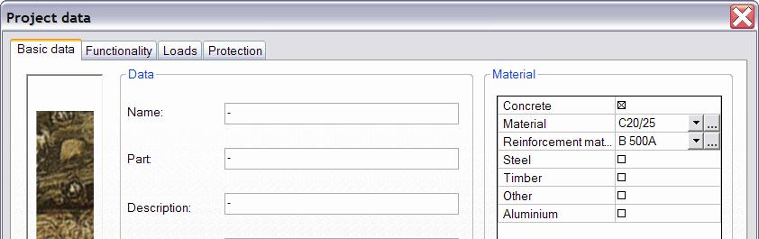
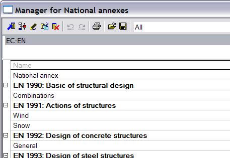
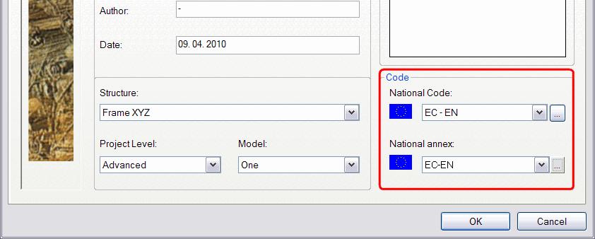

4 Introduction Code settings in Scia Engineer 2 Section 1 General 3
5 Section 1 General Scope of Eurocode 2 Design of buildings and civil engineering works in plain, reinforced and prestressed concrete Requirements for resistance, serviceability, durability and fire resistance of concrete structures Eurocode 2 is subdivided into the following parts: Part 1-1: General rules and rules for buildings Part 1-2: Structural fire design Part 2: Reinforced and prestressed concrete bridges Part 3: Liquid retaining and containing structure Focus in this workshop: Reinforced concrete Part Section 1 General Scope of Part 1-1 of Eurocode 2 General basis for design of structures in plain, reinforced and prestressed concrete made with normal and light weight aggregates together with specific rules for buildings Section 1: General Section 2: Basis of design Section 3: Materials Section 4: Durability and cover to reinforcement Section 5: Structural analysis Section 6: Ultimate limit states Section 7: Serviceability limit states Section 8: Detailing of reinforcement and prestressing tendons - General Section 9: Detailing of members and particular rules Section 10: Section 11: Section 12: Additional rules for precast concrete elements and structures Lightweight aggregate concrete structures Plain and lightly reinforced concrete structures Focus in this workshop: Sections 1 to 9 5
6 Section 2 Basis of design 6 Section 2 Basis of design Basic variables Material and product properties - general rules see EN 1990 Section 4 - specific provisions for concrete & reinforcement see EN 1992 Section 3 Shrinkage and creep - time dependent - effects have to be taken into account in the SLS - in the ULS: only if significant (for example 2 nd order) - quasi-permanent combination of loads Application in Scia Engineer: Creep: CDD or PNL calculation Shrinkage: TDA calculation 7

7 Section 2 Basis of design Verification by the partial factor method Design values Partial factors for shrinkage, prestress, fatigue loads Partial factors for materials - ULS: recommended values - SLS: recommended values γ c and γ s = 1 8 Section 2 Basis of design Verification by the partial factor method Design values Partial factors in Scia Engineer 9
8 Section 3 Materials 10 Section 3 Materials Concrete Characteristic strength Compressive strength - denoted by concrete strength classes (e.g. C25/30) - cylinder strength f ck and cube strength f ck,cube - f ck determined at 28 days If required to specify f ck (t) at time t for a number of stages (e.g. demoulding, transfer of prestress): f ck (t) = f cm (t) - 8 [MPa] f ck (t) = f ck for 3 < t < 28 days for t 28 days where f cm (t) = β cc (t) f cm withβ cc (t) dependent on the cement class 11


9 Section 3 Materials Concrete EN Table 3.1 Strength and deformation characteristics for concrete 12 Section 3 Materials Concrete Material characteristics in Scia Engineer 13
10 Section 3 Materials Concrete Design strength Design compressive strength f cd = α cc f ck / γ C (3.15) Design tensile strength f ctd = α ct f ctk,0,05 /γ C (3.16) α cc (resp. α ct ) is a coefficient taking account of long term effects on the compressive strength (resp. tensile strength) and of unfavourable effects resulting from the way the load is applied. α cc = 1,0 and α ct = 1,0 (recommended values) 14 Section 3 Materials Concrete Elastic deformation - dependent on composition of the concrete (especially the aggregates) - approximate values for modulus of elasticity E cm, secant value between σ c = 0 and 0,4f cm : see EN Table 3.1(for quartzite aggregates) Reduction for limestone aggregates (10%) sandstone aggregates (30%) Augmentation for basalt aggregates (20%) - variation of the modulus of elasticity with time: E cm (t) = (f cm (t) / f cm ) 0,3 E cm (3.5) - Poisson s ratio: 0,2 for uncracked concrete and 0 for cracked concrete 15
11 Section 3 Materials Concrete Creep and shrinkage dependent on - ambient humidity - dimensions of the element - composition of the concrete - maturity of the concrete at first loading - duration and magnitude of the loading Creep coefficient in Scia Engineer 16 Section 3 Materials Concrete Stress-strain relation for non-linear structural analysis Remark: the use of 0,4f cm for the definition of E cm is approximate! 17
12 Section 3 Materials Concrete Stress-strain relations for the design of cross-sections ε c2,3 : strain at reaching the maximum strength ε cu2,3 : ultimate strain (see EN Table 3.1) 18 Section 3 Materials Concrete Stress-strain relations for the design of cross-sections in Scia Engineer 19
 - maximum actual yield strength (f y,max ) - tensile strength (f t ) - ductility (ε uk and f t /f yk ) -")

13 Section 3 Materials Reinforcing Steel Properties The behaviour of reinforcing steel is specified by the following properties: - yield strength (f yk or f 0,2k ) - maximum actual yield strength (f y,max ) - tensile strength (f t ) - ductility (ε uk and f t /f yk ) - bendability - bond characteristics (f R : see Annex C) - section sizes and tolerances - fatigue strength - weldability - shear and weld strength for welded fabric and lattice girders 20 Section 3 Materials Reinforcing Steel Material characteristics in Scia Engineer 21
14 Section 3 Materials Reinforcing Steel Specified yield strength range: f yk = 400 to 600 MPa Specific properties for classes A B C: see Annex C Class A is used by default; B and C have more rotation capacity. 22 Section 3 Materials Reinforcing Steel Stress-strain diagrams of typical reinforcing steel - yield strength f yk (or the 0,2% proof stress, f 0,2k ) - tensile strength f tk - adequate ductility is necessary, defined by the (f t /f y ) k and ε uk 23
15 Section 3 Materials Reinforcing Steel Stress-strain diagrams for design R Recommended value: ε ud = 0,9 ε uk Assumptions for design: (a) inclined top branch with a strain limit of ε ud and a maximum stress of kf yk /γ s at ε uk (b) horizontal top branch without the check of strain limit 24 Section 3 Materials Reinforcing Steel Stress-strain diagrams for design in Scia Engineer 25
16 Section 4 Durability and cover to reinforcement 26 Section 4 Durability and cover to reinforcement Environmental Conditions EN Table 4.1 Exposure classes related to environmental conditions 27
17 Section 4 Durability and cover to reinforcement Methods of verification Concrete cover Nominal cover c nom = c min + Δc dev (4.1) c min, minimum cover, in order to ensure: - the safe transmission of bond forces - the protection of the steel against corrosion (durability) - an adequate fire resistance (see EN ) Δc dev, allowance in design for deviation 28 Section 4 Durability and cover to reinforcement Methods of verification Concrete cover Minimum cover, c min c min = max { c min,b ; c min,dur + Δc dur,g -Δc dur,st -Δc dur,add ; 10 mm } (4.2) where: c min,b minimum cover due to bond requirement c min,dur minimum cover due to environmental conditions Δc dur,g additive safety element Δc dur,st reduction of minimum cover for use of stainless steel Δc dur,add reduction of minimum cover for use of additional protection Allowance in design for deviation, Δc dev Δc dev = 10 mm (recommended value) 29

18 Section 4 Durability and cover to reinforcement Methods of verification Concrete cover in Scia Engineer 30 Section 5 Structural Analysis 31

")
19 Section 5 Structural Analysis Idealisation of the structure Structural models for overall analysis The elements of a structure are classified, by consideration of their nature and function, as beams, columns, slabs, walls, plates, arches, shells etc. Rules are provided for the analysis of the commoner of these elements and of structures consisting of combinations of these elements. See EN for the descriptions 32 Section 5 Structural Analysis Idealisation of the structure Assignment of structural models in Scia Engineer For 1D members: 3 types (beam, column, beam slab) choice made by user! Different calculation methods! For 2D members: 3 types (plate, wall, shell) detected by NEDIM solver, based on present internal forces 33
20 Section 5 Structural Analysis Idealisation of the structure Assignment of structural models in Scia Engineer Beam calculation Column calculation Z Z Difference in reinforcement area per direction Y Y Internal forces taken into account: Beam calculation: N, M y, V z Column calculation: N, M y, M z, V z 34 Section 5 Structural Analysis Idealisation of the structure Geometric data Continuous slabs and beams may generally be analysed on the assumption that the supports provide no rotational restraint. Monolithic connection (Fixed support) Critical design moment at the support = Moment at the face of the support Hinged support Design support moment may be reduced by an amount ΔM Ed : ΔM Ed = F Ed,sup t / 8 (5.9) where: F Ed,sup is the design support reaction t is the breadth of the support 35


")

21 Section 5 Structural Analysis Idealisation of the structure Moment reduction above support in Scia Engineer Nodal support Column support 36 Section 5 Structural Analysis Idealisation of the behaviour Common idealisations of the behaviour used for analysis are: (a) linear elastic behaviour (b) linear elastic behaviour with limited redistribution (c) plastic behaviour, including strut and tie models (d) non-linear behaviour 37


22 Section 5 Structural Analysis (a) Linear elastic analysis Based on the theory of elasticity Suitable for both ULS and SLS Assumptions: - uncracked cross-sections - linear stress-strain relationships - mean value of E For thermal deformation, settlement and shrinkage effects: - at ULS: reduced stiffness (cracking - tension stiffening + creep) - at SLS: gradual evolution of cracking Linear elastic analysis in Scia Engineer Linear calculation 38 Section 5 Structural Analysis (b) Linear elastic analysis with limited redistribution Principle of redistribution of bending moment Application For analysis of structural members for the verification of ULS. 39
23 Section 5 Structural Analysis (b) Linear elastic analysis with limited redistribution The moments at ULS calculated using a linear elastic analysis may be redistributed, provided that the resulting distribution of moments remains in equilibrium with the applied loads. Redistribution of bending moments, without explicit check on the rotation capacity, is allowed in continuous beams or slabs provided that: - they are predominantly subject to flexure - the ratio of the lengths of adjacent spans is in the range of 0,5 to 2 - δ k 1 + k 2 x u /d for f ck 50 MPa (5.10a) δ k 3 + k 4 x u /d for f ck > 50 MPa (5.10b) k 5 where Class B and Class C reinforcement is used (see EN Annex C) k 6 where Class A reinforcement is used (see EN Annex C) 40 Section 5 Structural Analysis (b) Linear elastic analysis with limited redistribution where: δ is the ratio of the redistributed moment to the elastic bending moment x u is the depth of the neutral axis at the ultimate limit state after redistribution d is the effective depth of the section k 1, k 2, k 3, k 4, k 5 and k 6 : see recommended values in National Annex Redistribution should not be carried out in circumstances where the rotation capacity cannot be defined with confidence. For the design of columns the elastic moments from frame action should be used without any redistribution. 41
24 Section 5 Structural Analysis (c) Plastic analysis Plastic analysis for beams, frames and slabs Only suitable for ULS Plastic analysis without any direct check of rotation capacity may be used, if the ductility of the critical sections is sufficient for the envisaged mechanism to be formed. The required ductility may be deemed to be satisfied without explicit verification if all the following are fulfilled: - the area of tensile reinforcement is limited such that, at any section x u /d 0,25 for concrete strength classes C50/60 x u /d 0,15 for concrete strength classes C55/67 - reinforcing steel is either Class B or C (see EN Annex C) - the ratio of the moments at intermediate supports to the moments in the span is between 0,5 and 2 42 Section 5 Structural Analysis (c) Plastic analysis Options for redistribution of bending moments & plastic analysis in Scia Engineer Available since Scia Engineer Choice for desired method in the Concrete Setup: 43

 & tension")
25 Section 5 Structural Analysis (c) Plastic analysis Analysis with strut-and-tie models Strut-and-tie models consist of - struts = compressive stress fields - ties = reinforcement - connecting nodes Forces: determined by maintaining the equilibrium with the applied loads in the ULS 44 Section 5 Structural Analysis (c) Plastic analysis Analysis with strut and tie models: Comparison deep beam slender beam Deep beam with pressure diagonals & tension tie Slender beam with pressure arch (D) & tension tie (T) 45


26 Section 5 Structural Analysis (c) Plastic analysis Analysis with strut and tie models in Scia Engineer Pressure only 2D members Trajectories result 46 Section 5 Structural Analysis (d) Non-linear analysis Suitable for both ULS and SLS, provided that equilibrium and compatibility are satisfied Non-linear behaviour for materials taken into account See EN Section 3 for the non-linear σ-ε diagrams The analysis may be first or second order Non-linear analysis in Scia Engineer 1 st order: PNL calculation 2 nd order: PGNL calculation 47
27 Section 5 Structural Analysis (d) Non-linear analysis Non-linear analysis in Scia Engineer: Plastic hinges Linear calculation Non-linear calculation Change of the stiffness in the concrete cross-section above the middle support due to cracks. The plastic resistance moment is reached. Redistribution of the moment line to satisfy the equilibrium of the structure Principle: Non-linear moment above the support + ½ Non-linear moment at the half of the span = Linear moment above the support 48 Section 5 Structural Analysis Geometric imperfections Definition of Geometric imperfections As consideration of the unfavourable effects of possible deviations in the geometry of the structure and the position of loads. (Deviations in cross-section dimensions material safety factors) To be taken into account both in 1 st and 2 nd order calculation. To be taken into account only in ULS (persistent and accidental design situations). To be taken into account only in the direction where they will have the most unfavourable effect. 49
28 Section 5 Structural Analysis Geometric imperfections General Imperfections may be represented by an inclination θ i : θ i = θ 0 α h α m (5.1) where: θ 0 is the basic value = 1/200 α h is the reduction factor for length or height (recommended value) α m is the reduction factor for number of vertical members contributing to the total effect 50 Section 5 Structural Analysis Geometric imperfections Isolated members 2 alternative ways to take geometric imperfections into account (1) As an eccentricity, e i, given by e i = θ i l 0 / 2 (5.2) where l 0 is the effective length For walls and isolated columns in braced systems, e i = l 0 / 400 may always be used as a simplification, corresponding to α h = 1. (2) As a transverse force, H i, in the position that gives the maximum moment: - for unbraced members: H i = θ i N (5.3a) - for braced members: H i = 2 θ i N (5.3b) where N is the axial load 51
29 Section 5 Structural Analysis Geometric imperfections Isolated members 2 alternative ways to take geometric imperfections into account 52 Section 5 Structural Analysis Geometric imperfections Minimum eccentricity for cross-section design e 0,min = max { h/30 ; 20 mm } see EN 6.1(4) where h is the depth of the section This means where: e 1 = 1 st order eccentricity e i = eccentricity due to geometric imperfections e 0 = e 1 + e i, design eccentricity in a 1 st order calculation 53
30 Section 5 Structural Analysis Analysis of second order effects with axial load Definitions First order effects: action effects calculated without consideration of the effect of structural deformations, but including geometric imperfections. Second order effects: additional action effects caused by structural deformations. They shall be taken into account where they are likely to affect the overall stability of a structure significantly; e.g. in case of columns, walls, piles, arches and shells. 54 Section 5 Structural Analysis Analysis of second order effects with axial load Criteria for 1 st or 2 nd order calculation 2 nd order effects have to be taken into account in each direction, unless they may be ignored acc. to one of the following articles: (a) 2 nd order effects may be ignored if they are less than 10 % of the corresponding 1 st order effects. (b) Simplified criterion = Slenderness criterion for isolated members 2 nd order effects may be ignored if the slenderness λ < λ lim In case of biaxial bending: the slenderness criterion may be checked separately for each direction 55
31 Section 5 Structural Analysis Analysis of second order effects with axial load Criteria for 1 st or 2 nd order calculation Slenderness ratio λ λ = l 0 / i (5.14) where: l 0 is the effective length i is the radius of gyration of the uncracked concrete section Limit slenderness λ lim λ lim = 20 A B C / n (recommended value, 5.13N) 56 Section 5 Structural Analysis Analysis of second order effects with axial load Criteria for 1 st or 2 nd order calculation Effective length - for isolated members 57
32 Section 5 Structural Analysis Analysis of second order effects with axial load Methods of analysis - Taking 2 nd order effects into account General method: Two simplified methods: based on non-linear 2 nd order analysis based on linear (nominal 2 nd order) analysis (a) Method based on nominal stiffness & moment magnification factor Use: both isolated members and whole structures (b) Method based on nominal curvature Use: mainly suitable for isolated members, but with realistic assumptions concerning the distribution of curvature, also for structures The selection of simplified method (a) and (b) to be used in a Country may be found in its National Annex. 58 Section 5 Structural Analysis Analysis of second order effects with axial load General method General method in Scia Engineer Real (physical and) geometrical non-linear calculation PGNL analysis for 1D members: non-linear σ ε diagram, new stiffness EI is calculated iteratively GNL analysis for 2D members: no non-linear σ ε diagram, but approximation of new stiffness EI by adapting value of E in the material library: or 59
33 Section 5 Structural Analysis Analysis of second order effects with axial load Simplified methods (a) Method based on nominal stiffness Nominal stiffness Moment magnification factor Total moment = 1 st and 2 nd order moment 60 Section 5 Structural Analysis Analysis of second order effects with axial load (b) Method based on nominal curvature Application For isolated members with constant normal force N and a defined effective length l 0. The method gives a nominal 2 nd order moment based on a deflection, which in turn is based on the effective length and an estimated maximum curvature. Design moment M Ed M Ed = M 0Ed + M 2 (5.31) where: M 0Ed is the 1 st order moment, including the effect of imperfections M 2 is the nominal 2 nd order moment, based on 1 st order internal forces 61
34 Section 5 Structural Analysis Analysis of second order effects with axial load (b) Method based on nominal curvature Nominal 2 nd order moment M 2 M 2 = N Ed e 2 (5.33) where: N Ed is the design value of axial force e 2 is the deflection = (1/r)*(l o ²/c) 1/r is the curvature l o is the effective length c is a factor depending on the curvature distribution For constant cross-section, c = 10 ( π 2 ) is normally used. If the first order moment is constant, a lower value should be considered (8 is a lower limit, corresponding to constant total moment). 62 Section 5 Structural Analysis Analysis of second order effects with axial load (b) Method based on nominal curvature Curvature 1/r 1/r = K r K ϕ 1/r 0 (5.34) where: K r is a correction factor depending on axial load K ϕ is a factor for taking account of creep 1/r 0 = ε yd / (0,45 d) ε yd = f yd / E s d is the effective depth 63


35 Section 5 Structural Analysis Analysis of second order effects with axial load (b) Method based on nominal curvature in Scia Engineer Linear calculation Taken into account for design: Buckling data OFF: - 1 st order moment Buckling data ON: - 1 st order moment - moment caused by geometrical imperfections - nominal 2 nd order moment, only ifλ> λlim 64 Section 5 Structural Analysis Analysis of second order effects with axial load (b) Method based on nominal curvature in Scia Engineer Overview 65
 If these conditions are NOT fulfilled bi-axial bending calculation is required 66 Section 5 Structural Analysis Analysis of second order")
36 Section 5 Structural Analysis Analysis of second order effects with axial load Bi-axial bending To decide if a bi-axial bending calculation is required or not, the following conditions should be checked: (slenderness ratios & relative eccentricities) If these conditions are NOT fulfilled bi-axial bending calculation is required 66 Section 5 Structural Analysis Analysis of second order effects with axial load Biaxial bending Simplified criterion = Interaction formula (5.39) where: M Edz/y is the design moment around the respective axis, including a 2 nd order moment (if required) M Rdz/y is the moment resistance in the respective direction a is the exponent; for circular and elliptical cross sections: a = 2; for rectangular cross sections: with linear interpolation for intermediate values 67

")
37 Section 5 Structural Analysis Analysis of second order effects with axial load Column calculation in Scia Engineer 68 Section 6 Ultimate limit states (ULS) 69
38 Section 6 Ultimate limit states (ULS) Bending with or without axial force Application Section 6 applies to undisturbed regions of beams, slabs and similar types of members for which sections remain approximately plane before and after loading. If plane sections do not remain plane see EN 6.5 (Design with strut and tie models) Ultimate moment resistance M Rd (or M u ) of reinforced concrete cross-sections Assumptions when determining M Rd : - plane sections remain plane - strain in bonded reinforcement = strain in the surrounding concrete - tensile strength of concrete is ignored - stresses in concrete in compression see design σ ε diagrams (EN 3.1.7) - stresses in reinforcing steel see design σ ε diagrams (EN 3.2.7) 70 Section 6 Ultimate limit states (ULS) Bending with or without axial force Strain limits Reinforcing steel Tensile strain limit = ε ud (where applicable) Concrete - In sections mainly subjected to bending Compressive strain limit = ε cu2 (or ε cu3 ) - In sections subjected to ± pure compression (± concentric loading (e d /h < 0,1), e.g. compression flanges of box girders, columns,...) Pure compressive strain limit = ε c2 (or ε c3 ) For concentrically loaded cross-sections with symmetrical reinforcement, assume as eccentricity (M Ed is at least = e 0 N Ed ) where h is the depth of the section 71
39 Section 6 Ultimate limit states (ULS) Bending with or without axial force Possible range of strain distributions (ULS) 72 Section 6 Ultimate limit states (ULS) Shear General verification procedure Definitions V Ed V Rd,c V Rd,s V Rd,max = design shear force resulting from external loading = design shear resistance of the member without shear reinforcement = design value of the shear force which can be sustained by the yielding shear reinforcement = design value of the maximum shear force which can be sustained by the member, limited by crushing of the concrete compression struts 73
40 Section 6 Ultimate limit states (ULS) Shear General verification procedure Definitions In members with inclined chords the following additional values are defined: V ccd V td = design value of the shear component of the force in the compression area, in the case of an inclined compression chord = design value of the shear component of the force in the tensile reinforcement, in the case of an inclined tensile chord Shear resistance of a member with shear reinforcement: V Rd = V Rd,s + V ccd + V td (6.1) 74 Section 6 Ultimate limit states (ULS) Shear General verification procedure Overview If V Ed V Rd,c No shear reinforcement required (theoretically), but minimum shear reinforcement should be provided for beams: ρ w,min = (0,08 f ck ) / f yk (recommended value, 9.5N) If V Ed > V Rd,c Shear reinforcement should be provided in order that V Ed V Rd In practice: V Rd,s = V Ed - V ccd - V td Check if V Rd,s (or V Ed ) V Rd,max (If V Ed > V Rd,max, failure by crushing of concrete compression struts!) 75

 1/3 + k 1 σ cp ] b w d (6.2a) with a minimum of V Rd,c = (v min + k 1 σ cp ) b w d (6.")
41 Section 6 Ultimate limit states (ULS) Shear Shear force reduction at supports For members subject to predominantly uniformly distributed loading, the design shear force need not to be checked at a distance less than d from the face of the support. Any shear reinforcement required should continue to the support.... in Scia Engineer 2 options: 76 Section 6 Ultimate limit states (ULS) Shear V Ed V Rd,c : Members not requiring design shear reinforcement Design value for the shear resistance V Rd,c V Rd,c = [C Rd,c k (100 ρ l f ck ) 1/3 + k 1 σ cp ] b w d (6.2a) with a minimum of V Rd,c = (v min + k 1 σ cp ) b w d (6.2b) where: k = 1 + (200/d) 2,0 with d in [mm] ρ l = A sl / b w d 0,02 is the longitudinal reinforcement ratio A sl is the area of the tensile reinforcement, which extends (l bd + d) beyond the section considered b w is the smallest width of the cross-section in the tensile area [mm] σ cp = N Ed /A c < 0,2 f cd [MPa] with N Ed > 0 for compression C Rd,c = 0,18 / γ c v min = 0,035 k 3/2. f ck 1/2 k 1 = 0,15 (recommended value) (recommended value, 6.3N) (recommended value) 77
42 Section 6 Ultimate limit states (ULS) Shear V Ed V Rd,c : Members not requiring design shear reinforcement V Ed should always satisfy the condition V Ed 0,5 b w d ν f cd (6.5) where: ν is a strength reduction factor for concrete cracked in shear ν = 0,6 [1 (f ck /250)] (recommended value, 6.6N) with f ck in [MPa] 78 Section 6 Ultimate limit states (ULS) Shear V Ed > V Rd,c : Members requiring design shear reinforcement The design of members with shear reinforcement is based on a truss model α = angle between the shear reinforcement and the beam axis θ = angle between the concrete compression strut and the beam axis 1 cotθ 2,5 (recommended limits, 6.7N) F td = design value of the tensile force in the longitudinal reinforcement F cd = design value of the concrete compression force z = the inner lever arm; the approximate value z = 0,9 d may normally be used 79
43 Section 6 Ultimate limit states (ULS) Shear V Ed > V Rd,c : Members requiring design shear reinforcement b w = minimum width between tension and compression chords 80 Section 6 Ultimate limit states (ULS) Shear V Ed > V Rd,c : Members requiring design shear reinforcement α = 90 (vertical shear reinforcement) V Rd is the smaller value of: V Rd,s = (A sw /s) z f ywd cotθ (6.8) and V Rd,max = α cw b w z ν 1 f cd / (cotθ + tanθ) (6.9) where: A sw is the cross-sectional area of the shear reinforcement s is the spacing of the stirrups f ywd is the design yield strength of the shear reinforcement ν 1 is a strength reduction factor for concrete cracked in shear α cw is a coefficient taking account of the state of the stress in the compression chord 81
44 Section 6 Ultimate limit states (ULS) Shear V Ed > V Rd,c : Members requiring design shear reinforcement α = 90 (vertical shear reinforcement) ν 1 = ν If σ wd < 0,80 f ywk, ν 1 may be taken as: (recommended value, 6.6N) ν 1 = 0,6 for f ck 60 MPa (6.10.aN) ν 1 = 0,9 f ck /200 > 0,5 for f ck 60 MPa (6.10.bN) If this Expression (6.10) is used, the value of f ywd should be reduced to 0,80 f ywk in Expression (6.8). α cw = 1 for non-prestressed structures (recommended value) A sw,max, for θ = 45 (cotθ = 1 and tanθ = 1), and V Rd,s = V Rd,max A sw,max /s = 0,5 α cw b w ν 1 f cd / f ywd (6.12) 82 Section 6 Ultimate limit states (ULS) Shear V Ed > V Rd,c : Members requiring design shear reinforcement α < 90 (inclined shear reinforcement) V Rd is the smaller value of: V Rd,s = (A sw /s) z f ywd (cotθ + cotα) sinα (6.13) and V Rd,max = α cw b w z ν 1 f cd (cotθ + cotα) / (1 + cot²θ) (6.14) A sw,max, for θ = 45 (cotθ = 1), and V Rd,s = V Rd,max A sw,max /s = (0,5 α cw b w ν 1 f cd ) / (f ywd sinα) (6.15) 83
45 Section 6 Ultimate limit states (ULS) Shear Explanation for V Rd,max Failure modes in case of shear (1) Shear-bending failure a) pattern of cracking in the SLS b) pattern of cracking in the ULS 84 Section 6 Ultimate limit states (ULS) Shear Explanation for V Rd,max Failure modes in case of shear (2) Shear-tension failure a) pattern of cracking in the SLS b) pattern of cracking in the ULS Adding enough shear reinforcement (in the form of verical stirrups) prevents shearbending and shear-tension failure. 85
46 Section 6 Ultimate limit states (ULS) Shear Explanation for V Rd,max Failure modes in case of shear (3) Shear-compression failure a) pattern of cracking in the SLS b) pattern of cracking in the ULS Imposing a maximum value V Rd,max to the shear force V Ed prevents sudden failure of the concrete compression strut before yielding of the shear reinforcement. 86 Section 6 Ultimate limit states (ULS) Shear Variable strut inclination method The strut inclination θ may be chosen between two limit values 1 cotθ 2,5 or 21,8 < θ < 45 (recommended limits, 6.7N) 1) Web uncracked in shear 2) Inclined cracks appear 3) Stabilization of inclined cracks 4) Yielding of stirrups further rotations and new cracks under lower angle finally failure by web crushing 87

 - Smaller angleθ larger stirrup spacing is sufficient = smaller value of A sw")
47 Section 6 Ultimate limit states (ULS) Shear Variable strut inclination method 88 Section 6 Ultimate limit states (ULS) Shear Variable strut inclination method Advantages of this method: Large freedom of design because of the large interval forθ By making a good choice for the inclination of the struts, optimal design can be achieved: - Larger angleθ higher value of V Rd,max (saving on concrete) - Smaller angleθ larger stirrup spacing is sufficient = smaller value of A sw (saving on steel) 89

48 Section 6 Ultimate limit states (ULS) Shear Variable strut inclination method General procedure which can be used in Scia Engineer: - Assumeθ= 21,8 (cotθ= 2,5) and calculate A sw - Check if V Ed > V Rd,max : If NO OK, end of design If YES crushing of the concrete strut - 3 options if V Rd,max is exceeded: - increase height of beam - choose higher concrete class - increaseθ, or calculateθfor which V Ed = V Rd,s and repeat the procedure 90 Section 6 Ultimate limit states (ULS) Shear Variable strut inclination method User input of angle θ (or cotangent θ) in Scia Engineer 91
49 Section 6 Ultimate limit states (ULS) Shear Additional tensile force in the longitudinal reinforcement... caused by shear 2 approaches (1) EN Section 6: For members with shear reinforcement Calculation of the additional tensile force,δf td, in the longitudinal reinforcement due to shear V Ed : ΔF td = 0,5 V Ed (cotθ - cotα) (6.18) (M Ed /z) + ΔF td M Ed,max /z, where M Ed,max is the maximum moment along the beam 92 Section 6 Ultimate limit states (ULS) Shear Additional tensile force in the longitudinal reinforcement... caused by shear (2) EN Section 9: For members without shear reinforcement ΔF td may be estimated by shifting the moment curve (in the region cracked in flexure) a distance a l = d in the unfavourable direction. For members with shear reinforcement This "shift rule" may also be used as an alternative to approach (1), where: a l = z (cotθ - cotα) / 2 (9.2) 93
50 Section 6 Ultimate limit states (ULS) Shear Additional tensile force in the longitudinal reinforcement... caused by shear The curtailment of longitudinal reinforcement, taking into account the effect of inclined cracks and the resistance of reinforcement bars within their anchorage lengths. (As a conservative simplification the contribution of the anchorage may be ignored.) 94 Section 6 Ultimate limit states (ULS) Shear Explanation for the additional tensile force a) reinforced concrete beam b) cracked beam with compression struts, after loading 95
 Shear Explanation for the additional tensile force Beam model N = M / z assume z = 1 Truss model Conclusion: Design of reinforcement according to beam model is unsafe shift of")
51 Section 6 Ultimate limit states (ULS) Shear Explanation for the additional tensile force c) truss analogy (θ = 45 ) d) internal forces in the members of the truss 96 Section 6 Ultimate limit states (ULS) Shear Explanation for the additional tensile force Beam model N = M / z assume z = 1 Truss model Conclusion: Design of reinforcement according to beam model is unsafe shift of M-line 97
52 Section 6 Ultimate limit states (ULS) Torsion General The torsional resistance of a section may be calculated on the basis of a thin-walled closed section, in which equilibrium is satisfied by a closed shear flow. Solid section equivalent thin-walled section Complex shape (e.g. T-sections) series of equivalent thin-walled section, where the total torsional resistance = sum of the capacities of the individual elements Non-solid sections equivalent wall thickness actual wall thickness 98 Section 6 Ultimate limit states (ULS) Torsion Design procedure Definitions The shear stress in a wall i of a section subject to a pure torsional moment: τ t,i t ef,i = T Ed / 2A k (6.26) The shear force V Ed,i in a wall i due to torsion is given by: V Ed,i = τ t,i t ef,i z i (6.27) where T Ed is the applied design torsion τ t,i is the torsional shear stress in wall i 99
53 Section 6 Ultimate limit states (ULS) Torsion A k is the area enclosed by the centre-lines of the connecting walls, including inner hollow areas t ef,i is the effective wall thickness, which may be taken as A/u A is the total area of the cross-section within the outer circumference, including inner hollow areas u is the outer circumference of the cross-section z i is the side length of wall i 100 Section 6 Ultimate limit states (ULS) Torsion Longitudinal reinforcement for torsion ΣA sl ΣA sl = (T Ed cotθ u k ) / (2 A k f yd ) (6.28) where: u k is the perimeter of the area A k f yd is the design yield stress of the longitudinal reinforcement A sl θ is the angle of compression struts In compressive chords: In tensile chords: The longitudinal reinf. may be reduced in proportion to the available compressive force. The longitudinal reinf. for torsion should be added to the other reinforcement. It should be distributed over the length of side, z i, but for smaller sections it may be concentrated at the ends of this length. 101
54 Section 6 Ultimate limit states (ULS) Torsion Transverse reinforcement for torsion (and shear) The effects of torsion (T) and shear (S) may be superimposed, assuming the same value for the strut inclination θ. Limits for θ are given in (6.7N). This means V Ed = V Ed (S) + V Ed (T) where: V Ed (T) = Σ V Ed,i (6.26) - (6.27) For each wall i: V Ed,i = τ t,i t ef,i z i = (T Ed z i ) / (2 A k ) (6.26) - (6.27) In practice: V Ed = V Rd,s = (A sw /s) z f ywd cot θ (6.8) 102 Section 6 Ultimate limit states (ULS) Torsion Specific conditions to be checked: Shear Torsion interaction diagrams 1 st Condition In order not to exceed the bearing capacity of the concrete struts for a member subjected to torsion and shear, the following condition should be satisfied: (T Ed / T Rd,max ) + (V Ed / V Rd,max ) 1 (6.29) where: T Ed is the design torsional moment & V Ed is the design transverse force T Rd,max is the design torsional resistance moment T Rd,max = 2 ν α cw f cd A k t ef,i sinθ cosθ (6.30) where ν follows from (6.6N) and α cw from (6.9) V Rd,max is the maximum design shear resistance according to (6.9) or (6.14). In solid cross-sections the full width of the web may be used to determine V Rd,max. 103
 + (V Ed / V Rd,c ) 1 (6.")
55 Section 6 Ultimate limit states (ULS) Torsion Specific conditions to be checked: Shear Torsion interaction diagrams 2 nd Condition For approximately rectangular solid sections, only minimum reinforcement is required if the following condition is satisfied: (T Ed / T Rd,c ) + (V Ed / V Rd,c ) 1 (6.31) where : T Rd,c is the torsional cracking moment, which may be determined by setting τ t,i = f ctd V Rd,c follows from (6.2) Minimum transverse reinforcement see ρ w,min (9.5N) 104 Section 6 Ultimate limit states (ULS) Torsion Torsion in Scia Engineer Not taken into account by default!! Torsion reinforcement is only calculated for the walls i // local z axis of the beam! For A sl : all of the required reinf. is distributed over the walls i // local z axis For A sw : only the required reinf. for V z (T) is caluculated, not the one for V y (T) 105
56 Section 6 Ultimate limit states (ULS) Punching General Punching = extension of the shear principles Punching shear results from a concentrated load or reaction, acting on a small area A load (the loaded area of a slab or a foundation) Verification model for checking punching failure at the ULS, based on control perimeters where checks will be performed. 106 Section 6 Ultimate limit states (ULS) Punching Verification model for checking punching failure at the ULS: 107
57 Section 6 Ultimate limit states (ULS) Punching Basic control perimeter u 1 Normally taken at a distance 2d from the loaded area: The effective depth d eff of the slab is assumed constant: d eff = (d y + d z ) / 2 (6.32) where d y and d z are the effective depths of the reinf. in 2 orthogonal directions In case the concentrated force is opposed by a high pressure (e.g. soil pressure on a column base), control perimeters at a distance less than 2d should be considered. 108 Section 6 Ultimate limit states (ULS) Punching Basic control perimeter u 1 In case of a loaded area near an opening: If the shortest distance between the perimeter of the loaded area and the edge of the opening 6d, the part of the control perimeter contained between two tangents is considered ineffective. 109
58 Section 6 Ultimate limit states (ULS) Punching Basic control perimeter u 1 In case of a loaded area near an edge or corner: If the distance to the edge or corner is smaller than d, special edge reinforcement should always be provided, see EN Further perimeters u i Further perimeters u i should have the same shape as the basic control perimeter u Section 6 Ultimate limit states (ULS) Punching Design procedure Based on checks at the face of the column and at the basic control perimeter u 1. If shear reinforcement is required, a further perimeter u out,ef should be found where shear reinforcement is no longer required. Definition of design shear resistances [MPa] ν Rd,c = ν Rd,cs = design value of the punching shear resistance of a slab without punching shear reinforcement along the control section considered design value of the punching shear resistance of a slab with punching shear reinforcement along the control section considered ν Rd,max = design value of the maximum punching shear resistance along the control section considered 111
59 Section 6 Ultimate limit states (ULS) Punching Design procedure Checks to be performed - Check at the face of the column, or at the perimeter of the loaded area (perimeter u 0 ): ν Ed0 ν Rd,max with v Ed0 the design shear stress at the column perimeter u 0 - Check at the basic control perimeter u 1 : If ν Ed ν Rd,c : Punching shear reinforcement is not required If ν Ed > ν Rd,c : Punching shear reinforcement has to be provided acc. to (6.52) with v Ed the design shear stress at the basic control perimeter u Section 6 Ultimate limit states (ULS) Punching Design procedure Remark: Where the support reaction is eccentric with regard to the control perimeter, the maximum shear stress should be taken as: v Ed = β V Ed / u i d (6.38) where: β can be calculated with the formulas in EN 6.4.3(3)-(4)-(5) Often, approximate values for β may be used: (recommended values for internal (A), edge (B) and corner(c) columns) 113
60 Section 6 Ultimate limit states (ULS) Punching Design procedure Remark: In case of a foundation slab, the punching shear force V Ed may be reduced due to the favourable action of the soil pressure. V Ed,red = V Ed -ΔV Ed (for concentric loading) (6.48) where: V Ed is the applied shear force ΔV Ed is the net upward force within the control perimeter considered, i.e. upward pressure from soil minus self weight of base v Ed = V Ed,red / u d (6.49) Remember: Consider control perimeters within 2d from the periphery of the column. 114 Section 6 Ultimate limit states (ULS) Punching V Ed V Rd,c : No punching shear reinforcement required Design punching shear resistance of a slab without shear reinforcement v Rd,c v Rd,c = C Rd,c k (100 ρ l f ck ) 1/3 + k 1 σ cp (v min + k 1 σ cp ) (6.47) where: C Rd,c = 0,18 / γ c v min = 0,035 k 3/2. f 1/2 ck k 1 = 0,1 (recommended value) (recommended value, 6.3N) (recommended value) Analogy with (6.2a) and (6.2b) 115
61 Section 6 Ultimate limit states (ULS) Punching V Ed > V Rd,c : Punching shear reinforcement required Design punching shear resistance of a slab with shear reinforcement v Rd,cs v Rd,cs = 0,75 v Rd,c + 1,5 (d/s r ) A sw f ywd,ef (1/(u 1 d)) sinα (6.52) where: A sw is the area of one perimeter of shear reinforcement around the column [mm 2 ] s r is the radial spacing of perimeters of shear reinforcement [mm] f ywd,ef is the effective design strength of the punching shear reinforcement, f ywd,ef = ,25 d f ywd [MPa] d is the mean of the effective depths in the orthogonal directions [mm] α is the angle between the shear reinforcement and the plane of the slab Analogy with (6.13) 116 Section 6 Ultimate limit states (ULS) Punching V Ed > V Rd,c : Punching shear reinforcement required Design punching shear resistance of a slab with shear reinforcement v Rd,cs v Rd,cs = 0,75 v Rd,c + 1,5 (d/s r ) A sw f ywd,ef (1/(u 1 d)) sinα (6.52) Explanation of the formula: v Rd,cs = 0,75 v Rd,c + v Rd,s - The contribution of the steel comes from the shear reinforcement at 1,5 d from the loaded area. - The contribution of the concrete is 75% of the resistance of a slab without punching shear reinforcement. 117
62 Section 6 Ultimate limit states (ULS) Punching V Ed > V Rd,c : Punching shear reinforcement required Design maximum punching shear resistance v Rd,max v Ed = β V Ed / u 0 d v Rd,max (6.53) v Rd,max = 0,5 ν f cd (recommended value) where u 0 for an interior column u 0 = length of column periphery [mm] for an edge column u 0 = c 2 + 3d c 2 + 2c 1 [mm] for a corner column u 0 = 3d c 1 + c 2 [mm] c 1, c 2 are the column dimensions ν see (6.6) β see EN 6.4.3(3)-(4)-(5)-(6) 118 Section 6 Ultimate limit states (ULS) Punching V Ed > V Rd,c : Punching shear reinforcement required Control perimeter at which shear reinforcement is no longer required, u out or u out,ef u out,ef = βv Ed / (v Rd,c d) (6.54) The outermost perimeter of shear reinforcement should be placed at a distance k d within u out or u out,eff : k = 1,5 (recommended value) 119
63 Section 7 Serviceability limit states (SLS) 120 Section 7 Serviceability limit states (SLS) General Common serviceability limit states Stress limitation Crack control Deflection control Other limit states, like vibration, are not covered in this Standard. 121
64 Section 7 Serviceability limit states (SLS) Stress limitation Limitation of the compressive stress in the concrete under the characteristic combination of loads... to avoid longitudinal cracks, micro-cracks or high levels of creep, where they could result in unacceptable effects on the function of the structure e. g. To avoid longitudinal cracks, which may lead to a reduction of durability: Limitation of the compressive stress to a value k 1 f ck, in areas exposed to environments of exposure classes XD, XF and X where k 1 = 0,6 (recommended value) Other (equivalent) measures: - an increase in the cover to reinforcement in the compressive zone - confinement by transverse reinforcement 122 Section 7 Serviceability limit states (SLS) Stress limitation Limitation of the compressive stress in the concrete under the quasi-permanent combination of loads... to avoid non-linear creep If σ c k 2 f ck If σ c > k 2 f ck linear creep may be assumed non-linear creep should be considered where k 2 = 0,45 (recommended value) 123
65 Section 7 Serviceability limit states (SLS) Stress limitation Limitation of the tensile stress in the reinforcement under the characteristic combination of loads... to avoid inelastic strain, unacceptable cracking or deformation e.g. To avoid unacceptable cracking or deformation: Limitation of the tensile stress to a value k 3 f yk where k 3 = 0,8 (recommended value) e.g. In case of an imposed deformation: Limitation of the tensile stress to a value k 4 f yk where k 4 = 1 (recommended value) 124 Section 7 Serviceability limit states (SLS) Crack control Principle Cracking of an axially loaded reinforced concrete column a. N c and N s in relation to the pattern of cracks b. Pattern of cracks in case of one large reinforcement bar c. Pattern of cracks in case of four small reinforcement bars 125
66 Section 7 Serviceability limit states (SLS) Crack control Limitation of cracking under the quasi-permanent combination of loads... to guarantee the proper functioning and durability of the structure, and acceptable appearance Cracking is normal in reinforced concrete structures! Cracks may be permitted to form without any attempt to control their width, provided that they do not impair the functioning of the structure. 126 Section 7 Serviceability limit states (SLS) Crack control Max. crack width w max w max = (recommended values, EN Table 7.1N)... taking into account the proposed function and nature of the structure and the costs of limiting cracking 127
67 Section 7 Serviceability limit states (SLS) Crack control Minimum reinforcement areas A minimum amount of bonded reinforcement is required to control cracking in areas where tension is expected. The amount may be estimated from equilibrium between the tensile force in concrete just before cracking and the tensile force in reinforcement at yielding. (or at a lower stress if necessary to limit the crack width) 128 Section 7 Serviceability limit states (SLS) Crack control Min. reinforcement area A s,min (within the tensile zone) A s,min = (k c k f ct,eff A ct ) / σ s (7.1) where: A ct is the area of concrete within the tensile zone, just before the formation of the first crack σ s is the maximum stress permitted in the reinforcement immediately after formation of the crack: σ s = f yk, unless a lower value is needed to satisfy the crack width limits according to the maximum bar size or spacing (see further) f ct,eff = f ctm or (f ctm (t)) if cracking is expected earlier than 28 days k = 1,0 for webs with h 300 mm or flanges with widths 300 mm = 0,65 for webs with h 800 mm or flanges with widths > 800 mm k c is a coefficient which takes account of the stress distribution within the section immediately prior to cracking and of the change of the lever arm 129
68 Section 7 Serviceability limit states (SLS) Crack control Two alternative methods for limitation of cracking: Calculation of crack widths, to check if w k w max Control of cracking without direct calculation, but by restricting the bar diameter or spacing (simplified method) 130 Section 7 Serviceability limit states (SLS) Crack control Control of cracking without direct calculation Where A s,min is provided, and for cracks caused mainly by loading, crack widths are unlikely to be excessive if: either the bar diameters (EN Table 7.2N) or the bar spacing (EN Table 7.3N) are not exceeded. - The steel stress should be calculated on the basis of a cracked section under the relevant combination of actions. - The values in the tables are based on the following assumptions: c = 25mm; f ct,eff = 2,9MPa; h cr = 0,5; (h-d) = 0,1h; k 1 = 0,8; k 2 = 0,5; k c = 0,4; k = 1,0; k t = 0,4 and k = 1,0 131
69 Section 7 Serviceability limit states (SLS) Crack control Control of cracking without direct calculation EN Table 7.2N Maximum bar diameters φ * s for crack control EN Table 7.3N Maximum bar spacing for crack control 132 Section 7 Serviceability limit states (SLS) Crack control Calculation of crack widths w k w k = s r,max (ε sm ε cm ) (7.8) where s r,max is the maximum crack spacing ε sm is the mean strain in the reinforcement under the relevant combination of loads, including the effect of imposed deformations and taking into account the effects of tension stiffening. ε cm is the mean strain in the concrete between cracks For the formulas for (ε sm ε cm ) and s r,max, see EN
70 Section 7 Serviceability limit states (SLS) Deflection control Principle M r = moment of 1 st cracking M y = yielding moment (steel) M Rd = moment of resistance (failure of concrete under compression) zone 0-1: no cracks zone 1-2: cracks arise and widen zone 2-4: cracks become visibly wide (control mechanism to failure) 134 Section 7 Serviceability limit states (SLS) Deflection control Limitation of deflection under the quasi-permanent combination of loads... to avoid adversely affection of the proper functioning or appearance Limitation of the calculated sag of a beam, slab or cantilever: 1/250 * span Limitation of deflections that could damage adjacent parts of the structure: 1/500 * span (deflection after construction) 135
71 Section 7 Serviceability limit states (SLS) Deflection control Two alternative methods for limitation of deflection: Calculation of deflection, to check if the calculated value the limit value Control of deflection without direct calculation, but by limiting the span/depth ratio 136 Section 7 Serviceability limit states (SLS) Deflection control Checking deflections by calculation Consideration of 2 conditions (I) uncracked condition (II) fully cracked condition Members which are expected to crack, but may not be fully cracked, will behave in a manner intermediate between the uncracked and fully cracked conditions. 137
72 Section 7 Serviceability limit states (SLS) Deflection control Checking deflections by calculation A prediction of behaviour (for members subjected mainly to flexure) is given by: α = ζ α II + (1 -ζ) α I (7.18) where: α is the deformation parameter considered, e.g. a strain, a curvature, a rotation, or as a simplification a deflection α I, α II are the values for the uncracked and fully cracked conditions ζ is a distribution coefficient (allowing for tensioning stiffening at a section) 138 Section 7 Serviceability limit states (SLS) Deflection control Checking deflections by calculation ζ = 1 β (σ sr /σ s )² (7.19) ζ = 0 for uncracked sections β is a coefficient taking account of the influence of the duration of the loading β = 1,0 for a single short-term loading β = 0,5 for sustained loads or many cycles of repeated loading σ s is the stress in the tension reinforcement calculated on the basis of a cracked section σ sr is the stress in the tension reinforcement calculated on the basis of a cracked section under the loading conditions causing first cracking Note: σ sr /σ s may be replaced by M cr /M for flexure or N cr /N for pure tension, where M cr is the cracking moment and N cr is the cracking force. 139
73 Section 7 Serviceability limit states (SLS) Deflection control Checking deflections by calculation Taking account of creep For loads with a duration causing creep, the total deformation including creep may be calculated by using an effective modulus of elasticity for concrete: E c,eff = E cm / [1 + φ(,t 0 )] (7.20) where: φ(,t 0 ) is the creep coefficient 140 Section 7 Serviceability limit states (SLS) Deflection control Checking deflections by calculation Most rigorous method of assessing deflections: Compute the curvatures at frequent sections along the member & calculate the deflection by numerical integration Do this twice, 1 st time: assuming the whole member to be uncracked (Condition I) 2 nd time: assuming the member to be fully cracked (Condition II) then interpolate using α = ζ α II + (1 -ζ) α I 141
 r is calculated: ( EI) r = ζ 1 1 ζ + ( EI) II ( EI) I (ζ = 0 for uncracked sections) (EI) I : short term")
74 Section 7 Serviceability limit states (SLS) Deflection control Deflection control in Scia Engineer = Code Dependent Deflection (CDD) calculation Using α = ζ α II + (1 -ζ) α I with deformation parameter α = reverse stiffness 1/EI Per finite mesh element, an equivalent stiffness (EI) r is calculated: ( EI) r = ζ 1 1 ζ + ( EI) II ( EI) I (ζ = 0 for uncracked sections) (EI) I : short term stiffness (uncracked condition) E = E cm I = based on total concrete css + reinf. area (EI) II : long term stiffness (fully cracked condition) E = E c,eff I = based on concrete css under compression + reinf. area 142 Section 7 Serviceability limit states (SLS) Deflection control Deflection control in Scia Engineer = Code Dependent Deflection (CDD) calculation The transition from the uncracked state (I) to the cracked state (II) does not occur abruptly, but gradually. From the appearance of the first crack, realistically, a parabolic curve can be followed which approaches the line for the cracked state (II). distribution coefficient ζ ( EI) r = ζ 1 1 ζ + ( EI) II ( EI) I 143
 calculation User input in Scia Engineer - The type of reinforcement for which")
 144 Dependent Deflection (CDD) calculation Concrete combinations CC1 (Immediate effect)")

75 Section 7 Serviceability limit states (SLS) Deflection control Deflection control in Scia Engineer = Code Dependent Deflection (CDD) calculation User input in Scia Engineer - The type of reinforcement for which the CDD calculation will be performed - The parameters for calculation of the creep coefficient (acc. to EN Annex B1) 144 Section 7 Serviceability limit states (SLS) Deflection control Deflection control in Scia Engineer = Code Dependent Deflection (CDD) calculation Concrete combinations CC1 (Immediate effect) 1,00 SW + 1,00 PL CC2 (Creep effect) 1,00 SW + 1,00 PL + 0,30 VL CC3 (Total effect) 1,00 SW + 1,00 PL + 1,00 VL 145
76 Section 7 Serviceability limit states (SLS) Deflection control Deflection control in Scia Engineer = Code Dependent Deflection (CDD) calculation 3 Concrete combinations ~ Mκ diagram used by NEN (Dutch code) 146 Section 7 Serviceability limit states (SLS) Deflection control CDD versus PNL calculation in Scia Engineer CDD (Code Dependent Deflection) calculation - The formulas take into account the influence of cracks and creep - Quasi non-linear calculation: EI is calculated according to approximate formulas - Code dependent PNL (Physical Non Linear) calculation - Takes into account the non-linear behaviour of materials, the influence of cracks and creep - Real non-linear calculation: EI is calculated iteratively - Code independent 147
77 Section 8 Detailing of reinforcement - General 148 Section 8 Detailing of reinforcement - General Spacing of bars Min. bar spacing s min The minimum clear distance (horizontal and vertical) between parallel bars should be s min = max { k 1 φ ; (d g + k 2 mm) ; 20 mm } where: d g is the maximum aggregate size k 1 = 1 mm k 2 = 5 mm (recommended value) (recommended value)... such that the concrete can be placed and compacted satisfactorily (by vibrators) for the development of adequate bond 149
78 Section 8 Detailing of reinforcement - General Permissible mandrel diameters for bent bars Min. mandrel diameter φ m,min φ m,min = (recommended values, EN Table 8.1N)... to avoid bending cracks in the bar, and to avoid failure of the concrete inside the bend of the bar 150 Section 8 Detailing of reinforcement - General Anchorage of longitudinal reinforcement Methods of anchorage... to ensure that the bond forces are safely transmitted to the concrete, avoiding longitudinal cracking or spalling 151
79 Section 8 Detailing of reinforcement - General Anchorage of longitudinal reinforcement Ultimate bond stress Design value of ultimate bond stress f bd f bd = 2,25 η 1 η 2 f ctd (8.2) where: f ctd is the design value of concrete tensile strength η 1 is a coefficient related to the quality of the bond condition and the position of the bar during concreting: η 1 = 1,0 η 1 = 0,7 ( good conditions) (all other cases) η 2 is related to the bar diameter: η 2 = 1,0 η 2 = (132 - φ)/100 for φ 32 mm for φ > 32 mm The ultimate bond strength shall be sufficient to prevent bond failure. 152 Section 8 Detailing of reinforcement - General Anchorage of longitudinal reinforcement Ultimate bond stress Description of bond conditions 153
80 Section 8 Detailing of reinforcement - General Anchorage of longitudinal reinforcement Basic anchorage length Basic required anchorage length l b,rqd l b,rqd = (φ / 4) (σ sd / f bd ) (8.3) for anchoring the force A s σ sd in a straight bar, assuming constant bond stress f bd and where σ sd is the design stress of the bar at the position from where the anchorage is measured from 154 Section 8 Detailing of reinforcement - General Anchorage of longitudinal reinforcement Design anchorage length Min. anchorage length l b,min l b,min max { 0,3l b,rqd ; 10φ ; 100 mm } (anchorages in tension) (8.6) l b,min max { 0,6l b,rqd ; 10φ ; 100 mm } (anchorages in compression) (8.7) Design anchorage length l bd l bd = α 1 α 2 α 3 α 4 α 5 l b,rqd l b,min (8.4) where α 1,α 2,α 3,α 4 and α 5 are coefficients given in EN Table 8.2, depending on shape of bar, concrete cover, type of confinement 155


81 Section 8 Detailing of reinforcement - General Anchorage of links and shear reinforcement Methods of anchorage - by means of bends and hooks, or by welded transverse reinforcement - a bar should be provided inside each hook or bend 156 Section 8 Detailing of reinforcement - General Anchorage of reinforcement Anchorage types in Scia Engineer Longitudinal reinforcement Stirrup reinforcement 157
Bending and Shear in Beams
 Bending and Shear in Beams Lecture 3 5 th October 017 Contents Lecture 3 What reinforcement is needed to resist M Ed? Bending/ Flexure Section analysis, singly and doubly reinforced Tension reinforcement,
Design of reinforced concrete sections according to EN and EN
 Design of reinforced concrete sections according to EN 1992-1-1 and EN 1992-2 Validation Examples Brno, 21.10.2010 IDEA RS s.r.o. South Moravian Innovation Centre, U Vodarny 2a, 616 00 BRNO tel.: +420-511
Practical Design to Eurocode 2
 Practical Design to Eurocode 2 The webinar will start at 12.30 (Any questions beforehand? use Questions on the GoTo Control Panel) Course Outline Lecture Date Speaker Title 1 21 Sep Jenny Burridge Introduction,
Lecture-04 Design of RC Members for Shear and Torsion
 Lecture-04 Design of RC Members for Shear and Torsion By: Prof. Dr. Qaisar Ali Civil Engineering Department UET Peshawar drqaisarali@uetpeshawar.edu.pk www.drqaisarali.com 1 Topics Addressed Design of
Department of Mechanics, Materials and Structures English courses Reinforced Concrete Structures Code: BMEEPSTK601. Lecture no. 6: SHEAR AND TORSION
 Budapest University of Technology and Economics Department of Mechanics, Materials and Structures English courses Reinforced Concrete Structures Code: BMEEPSTK601 Lecture no. 6: SHEAR AND TORSION Reinforced
PLATE GIRDERS II. Load. Web plate Welds A Longitudinal elevation. Fig. 1 A typical Plate Girder
 16 PLATE GIRDERS II 1.0 INTRODUCTION This chapter describes the current practice for the design of plate girders adopting meaningful simplifications of the equations derived in the chapter on Plate Girders
CHAPTER 6: ULTIMATE LIMIT STATE
 CHAPTER 6: ULTIMATE LIMIT STATE 6.1 GENERAL It shall be in accordance with JSCE Standard Specification (Design), 6.1. The collapse mechanism in statically indeterminate structures shall not be considered.
Detailing. Lecture 9 16 th November Reinforced Concrete Detailing to Eurocode 2
 Detailing Lecture 9 16 th November 2017 Reinforced Concrete Detailing to Eurocode 2 EC2 Section 8 - Detailing of Reinforcement - General Rules Bar spacing, Minimum bend diameter Anchorage of reinforcement
CHAPTER 4. ANALYSIS AND DESIGN OF COLUMNS
 4.1. INTRODUCTION CHAPTER 4. ANALYSIS AND DESIGN OF COLUMNS A column is a vertical structural member transmitting axial compression loads with or without moments. The cross sectional dimensions of a column
Annex - R C Design Formulae and Data
 The design formulae and data provided in this Annex are for education, training and assessment purposes only. They are based on the Hong Kong Code of Practice for Structural Use of Concrete 2013 (HKCP-2013).
CHAPTER 4. Design of R C Beams
 CHAPTER 4 Design of R C Beams Learning Objectives Identify the data, formulae and procedures for design of R C beams Design simply-supported and continuous R C beams by integrating the following processes
EUROCODE EN SEISMIC DESIGN OF BRIDGES
 Brussels, 18-20 February 2008 Dissemination of information workshop 1 EUROCODE EN1998-2 SEISMIC DESIGN OF BRIDGES Basil Kolias Basic Requirements Brussels, 18-20 February 2008 Dissemination of information
SERVICEABILITY LIMIT STATE DESIGN
 CHAPTER 11 SERVICEABILITY LIMIT STATE DESIGN Article 49. Cracking Limit State 49.1 General considerations In the case of verifications relating to Cracking Limit State, the effects of actions comprise
Serviceability Limit States
 Serviceability Limit States www.eurocode2.info 1 Outline Crack control and limitations Crack width calculations Crack width calculation example Crack width calculation problem Restraint cracking Deflection
Flexure: Behavior and Nominal Strength of Beam Sections
 4 5000 4000 (increased d ) (increased f (increased A s or f y ) c or b) Flexure: Behavior and Nominal Strength of Beam Sections Moment (kip-in.) 3000 2000 1000 0 0 (basic) (A s 0.5A s ) 0.0005 0.001 0.0015
Practical Design to Eurocode 2. The webinar will start at 12.30
 Practical Design to Eurocode 2 The webinar will start at 12.30 Course Outline Lecture Date Speaker Title 1 21 Sep Jenny Burridge Introduction, Background and Codes 2 28 Sep Charles Goodchild EC2 Background,
- Rectangular Beam Design -
 Semester 1 2016/2017 - Rectangular Beam Design - Department of Structures and Material Engineering Faculty of Civil and Environmental Engineering University Tun Hussein Onn Malaysia Introduction The purposes
Design of Beams (Unit - 8)
") Design of Beams (Unit - 8) Contents Introduction Beam types Lateral stability of beams Factors affecting lateral stability Behaviour of simple and built - up beams in bending (Without vertical stiffeners)
Design of Beams (Unit - 8) Contents Introduction Beam types Lateral stability of beams Factors affecting lateral stability Behaviour of simple and built - up beams in bending (Without vertical stiffeners)
Chapter. Materials. 1.1 Notations Used in This Chapter
 Chapter 1 Materials 1.1 Notations Used in This Chapter A Area of concrete cross-section C s Constant depending on the type of curing C t Creep coefficient (C t = ε sp /ε i ) C u Ultimate creep coefficient
Design of AAC wall panel according to EN 12602
 Design of wall panel according to EN 160 Example 3: Wall panel with wind load 1.1 Issue Design of a wall panel at an industrial building Materials with a compressive strength 3,5, density class 500, welded
CE5510 Advanced Structural Concrete Design - Design & Detailing of Openings in RC Flexural Members-
 CE5510 Advanced Structural Concrete Design - Design & Detailing Openings in RC Flexural Members- Assoc Pr Tan Kiang Hwee Department Civil Engineering National In this lecture DEPARTMENT OF CIVIL ENGINEERING
Fundamentals of Structural Design Part of Steel Structures
 Fundamentals of Structural Design Part of Steel Structures Civil Engineering for Bachelors 133FSTD Teacher: Zdeněk Sokol Office number: B619 1 Syllabus of lectures 1. Introduction, history of steel structures,
ε t increases from the compressioncontrolled Figure 9.15: Adjusted interaction diagram
 CHAPTER NINE COLUMNS 4 b. The modified axial strength in compression is reduced to account for accidental eccentricity. The magnitude of axial force evaluated in step (a) is multiplied by 0.80 in case
Concise Eurocode 2 25 February 2010
 Concise Eurocode 2 25 February 2010 Revisions required to Concise Eurocode 2 (Oct 06 edition) due to revisions in standards, notably Amendment 1 to NA to BS EN 1992-1-1:2004 dated Dec 2009, and interpretations.
Influence of residual stresses in the structural behavior of. tubular columns and arches. Nuno Rocha Cima Gomes
 October 2014 Influence of residual stresses in the structural behavior of Abstract tubular columns and arches Nuno Rocha Cima Gomes Instituto Superior Técnico, Universidade de Lisboa, Portugal Contact:
Chapter 8. Shear and Diagonal Tension
 Chapter 8. and Diagonal Tension 8.1. READING ASSIGNMENT Text Chapter 4; Sections 4.1-4.5 Code Chapter 11; Sections 11.1.1, 11.3, 11.5.1, 11.5.3, 11.5.4, 11.5.5.1, and 11.5.6 8.2. INTRODUCTION OF SHEAR
Sabah Shawkat Cabinet of Structural Engineering Walls carrying vertical loads should be designed as columns. Basically walls are designed in
 Sabah Shawkat Cabinet of Structural Engineering 17 3.6 Shear walls Walls carrying vertical loads should be designed as columns. Basically walls are designed in the same manner as columns, but there are
9.5 Compression Members
 9.5 Compression Members This section covers the following topics. Introduction Analysis Development of Interaction Diagram Effect of Prestressing Force 9.5.1 Introduction Prestressing is meaningful when
Einführung des EC2 in Belgien The introduction of EC2 in Belgium
 Luc Taerwe 1 Einführung des EC2 in Belgien The introduction of EC2 in Belgium Luc Taerwe Univ.-Prof. Dr.-Ing. habil. Luc Taerwe - graduated as civil engineer at Ghent University (1975) where he also obtained
Civil Engineering Design (1) Design of Reinforced Concrete Columns 2006/7
 Design of Reinforced Concrete Columns 2006/7") Civil Engineering Design (1) Design of Reinforced Concrete Columns 2006/7 Dr. Colin Caprani, Chartered Engineer 1 Contents 1. Introduction... 3 1.1 Background... 3 1.2 Failure Modes... 5 1.3 Design Aspects...
Civil Engineering Design (1) Design of Reinforced Concrete Columns 2006/7 Dr. Colin Caprani, Chartered Engineer 1 Contents 1. Introduction... 3 1.1 Background... 3 1.2 Failure Modes... 5 1.3 Design Aspects...
3. Stability of built-up members in compression
 3. Stability of built-up members in compression 3.1 Definitions Build-up members, made out by coupling two or more simple profiles for obtaining stronger and stiffer section are very common in steel structures,
10/14/2011. Types of Shear Failure. CASE 1: a v /d 6. a v. CASE 2: 2 a v /d 6. CASE 3: a v /d 2
 V V Types o Shear Failure a v CASE 1: a v /d 6 d V a v CASE 2: 2 a v /d 6 d V a v CASE 3: a v /d 2 d V 1 Shear Resistance Concrete compression d V cz = Shear orce in the compression zone (20 40%) V a =
STEEL BUILDINGS IN EUROPE. Multi-Storey Steel Buildings Part 10: Technical Software Specification for Composite Beams
 STEEL BUILDINGS IN EUROPE Multi-Storey Steel Buildings Part 10: Technical Software Specification for Composite Beams Multi-Storey Steel Buildings Part 10: Technical Software Specification for Composite
Practical Design to Eurocode 2
 Practical Design to Eurocode 2 The webinar will start at 12.30 (I m happy to field individual questions beforehand Use Questions on the shown Control Panel) Course Outline Lecture Date Speaker Title 1
Standardisation of UHPC in Germany
 Standardisation of UHPC in Germany Part II: Development of Design Rules, University of Siegen Prof. Dr.-Ing. Ekkehard Fehling, University of Kassel 1 Overvie Introduction: Work of the Task Group Design
NUMERICAL EVALUATION OF THE ROTATIONAL CAPACITY OF STEEL BEAMS AT ELEVATED TEMPERATURES
 8 th GRACM International Congress on Computational Mechanics Volos, 12 July 15 July 2015 NUMERICAL EVALUATION OF THE ROTATIONAL CAPACITY OF STEEL BEAMS AT ELEVATED TEMPERATURES Savvas Akritidis, Daphne
Design of Reinforced Concrete Beam for Shear
 Lecture 06 Design of Reinforced Concrete Beam for Shear By: Prof Dr. Qaisar Ali Civil Engineering Department UET Peshawar drqaisarali@uetpeshawar.edu.pk 1 Topics Addressed Shear Stresses in Rectangular
Concrete and Masonry Structures 1 Office hours
 Concrete and Masonry Structures 1 Petr Bílý, office B731 http://people.fsv.cvut.cz/www/bilypet1 Courses in English Concrete and Masonry Structures 1 Office hours Credit receiving requirements General knowledge
Structural Steelwork Eurocodes Development of A Trans-national Approach
 Structural Steelwork Eurocodes Development of A Trans-national Approach Course: Eurocode Module 7 : Worked Examples Lecture 0 : Simple braced frame Contents: 1. Simple Braced Frame 1.1 Characteristic Loads
Job No. Sheet No. Rev. CONSULTING Engineering Calculation Sheet. Member Design - Reinforced Concrete Beam BS8110 v Member Design - RC Beam XX
 CONSULTING Engineering Calculation Sheet E N G I N E E R S Consulting Engineers jxxx 1 Effects From Structural Analysis Design axial force, F (tension -ve and compression +ve) (ensure < 0.1f cu b w h 0
Seismic Pushover Analysis Using AASHTO Guide Specifications for LRFD Seismic Bridge Design
 Seismic Pushover Analysis Using AASHTO Guide Specifications for LRFD Seismic Bridge Design Elmer E. Marx, Alaska Department of Transportation and Public Facilities Michael Keever, California Department
Accordingly, the nominal section strength [resistance] for initiation of yielding is calculated by using Equation C-C3.1.
![Accordingly, the nominal section strength [resistance] for initiation of yielding is calculated by using Equation C-C3.1.](/thumbs/89/98617066.jpg "Accordingly, the nominal section strength [resistance] for initiation of yielding is calculated by using Equation C-C3.1.") C3 Flexural Members C3.1 Bending The nominal flexural strength [moment resistance], Mn, shall be the smallest of the values calculated for the limit states of yielding, lateral-torsional buckling and distortional
C3 Flexural Members C3.1 Bending The nominal flexural strength [moment resistance], Mn, shall be the smallest of the values calculated for the limit states of yielding, lateral-torsional buckling and distortional
NAGY GYÖRGY Tamás Assoc. Prof, PhD
 NAGY GYÖRGY Tamás Assoc. Prof, PhD E mail: tamas.nagy gyorgy@upt.ro Tel: +40 256 403 935 Web: http://www.ct.upt.ro/users/tamasnagygyorgy/index.htm Office: A219 SIMPLE SUPORTED BEAM b = 15 cm h = 30 cm
Design of a Multi-Storied RC Building
 Design of a Multi-Storied RC Building 16 14 14 3 C 1 B 1 C 2 B 2 C 3 B 3 C 4 13 B 15 (S 1 ) B 16 (S 2 ) B 17 (S 3 ) B 18 7 B 4 B 5 B 6 B 7 C 5 C 6 C 7 C 8 C 9 7 B 20 B 22 14 B 19 (S 4 ) C 10 C 11 B 23
DEFORMATION CAPACITY OF OLDER RC SHEAR WALLS: EXPERIMENTAL ASSESSMENT AND COMPARISON WITH EUROCODE 8 - PART 3 PROVISIONS
 DEFORMATION CAPACITY OF OLDER RC SHEAR WALLS: EXPERIMENTAL ASSESSMENT AND COMPARISON WITH EUROCODE 8 - PART 3 PROVISIONS Konstantinos CHRISTIDIS 1, Emmanouil VOUGIOUKAS 2 and Konstantinos TREZOS 3 ABSTRACT
Delhi Noida Bhopal Hyderabad Jaipur Lucknow Indore Pune Bhubaneswar Kolkata Patna Web: Ph:
 Serial : IG1_CE_G_Concrete Structures_100818 Delhi Noida Bhopal Hyderabad Jaipur Lucknow Indore Pune Bhubaneswar Kolkata Patna Web: E-mail: info@madeeasy.in Ph: 011-451461 CLASS TEST 018-19 CIVIL ENGINEERING
Finite Element Modelling with Plastic Hinges
 01/02/2016 Marco Donà Finite Element Modelling with Plastic Hinges 1 Plastic hinge approach A plastic hinge represents a concentrated post-yield behaviour in one or more degrees of freedom. Hinges only
Bridge deck modelling and design process for bridges
 EU-Russia Regulatory Dialogue Construction Sector Subgroup 1 Bridge deck modelling and design process for bridges Application to a composite twin-girder bridge according to Eurocode 4 Laurence Davaine
RETAINING WALL ANALYSIS
 Retaining Wall Analysis Example (EN997:2004) GEODOMISI Ltd. Dr. Costas Sachpazis Consulting Company for Tel.: (+30) 20 523827, 20 57263 Fax.:+30 20 5746 App'd by RETAINING WALL ANALYSIS In accordance with
Lecture-03 Design of Reinforced Concrete Members for Flexure and Axial Loads
 Lecture-03 Design of Reinforced Concrete Members for Flexure and Axial Loads By: Prof. Dr. Qaisar Ali Civil Engineering Department UET Peshawar drqaisarali@uetpeshawar.edu.pk www.drqaisarali.com Prof.
RETAINING WALL ANALYSIS
 GEODOMISI Ltd. Dr. Costas Sachpazis Consulting Company for Tel.: (+30) 20 523827, 20 57263 Fax.:+30 20 5746 Retaining wall Analysis & Design (EN997:2004 App'd by RETAINING WALL ANALYSIS In accordance with
Lecture-05 Serviceability Requirements & Development of Reinforcement
 Lecture-05 Serviceability Requirements & Development of Reinforcement By: Prof Dr. Qaisar Ali Civil Engineering Department UET Peshawar drqaisarali@uetpeshawar.edu.pk www.drqaisarali.com 1 Section 1: Deflections
Appendix K Design Examples
 Appendix K Design Examples Example 1 * Two-Span I-Girder Bridge Continuous for Live Loads AASHTO Type IV I girder Zero Skew (a) Bridge Deck The bridge deck reinforcement using A615 rebars is shown below.
O Dr Andrew Bond (Geocentrix)
") DECODING EUROCODES 2 + 7: DESIGN SG OF FOUNDATIONS O Dr Andrew Bond (Geocentrix) Outline of talk April 2010: the death of British Standards? UK implementation of Eurocodes Verification of strength: limit
DECODING EUROCODES 2 + 7: DESIGN SG OF FOUNDATIONS O Dr Andrew Bond (Geocentrix) Outline of talk April 2010: the death of British Standards? UK implementation of Eurocodes Verification of strength: limit
Redistribution of force concentrations in reinforced concrete cantilever slab using 3D non-linear FE analyses
 y x m y m y Linear elastic isotropic Linear elastic orthotropic Plastic Redistribution of force concentrations in reinforced concrete cantilever slab using 3D non-linear FE analyses x Master of Science
Composite bridge design (EN1994-2) Bridge modelling and structural analysis
 Bridge modelling and structural analysis") EUROCODES Bridges: Background and applications Dissemination of information for training Vienna, 4-6 October 2010 1 Composite bridge design (EN1994-2) Bridge modelling and structural analysis Laurence
EUROCODES Bridges: Background and applications Dissemination of information for training Vienna, 4-6 October 2010 1 Composite bridge design (EN1994-2) Bridge modelling and structural analysis Laurence
PERIYAR CENTENARY POLYTECHNIC COLLEGE PERIYAR NAGAR - VALLAM THANJAVUR. DEPARTMENT OF MECHANICAL ENGINEERING QUESTION BANK
 PERIYAR CENTENARY POLYTECHNIC COLLEGE PERIYAR NAGAR - VALLAM - 613 403 - THANJAVUR. DEPARTMENT OF MECHANICAL ENGINEERING QUESTION BANK Sub : Strength of Materials Year / Sem: II / III Sub Code : MEB 310
Mechanics of Materials Primer
 Mechanics of Materials rimer Notation: A = area (net = with holes, bearing = in contact, etc...) b = total width of material at a horizontal section d = diameter of a hole D = symbol for diameter E = modulus
Design of Reinforced Concrete Structures (II)
") Design of Reinforced Concrete Structures (II) Discussion Eng. Mohammed R. Kuheil Review The thickness of one-way ribbed slabs After finding the value of total load (Dead and live loads), the elements are
Design of Reinforced Concrete Structures (II) Discussion Eng. Mohammed R. Kuheil Review The thickness of one-way ribbed slabs After finding the value of total load (Dead and live loads), the elements are
INFLUENCE OF FLANGE STIFFNESS ON DUCTILITY BEHAVIOUR OF PLATE GIRDER
 International Journal of Civil Structural 6 Environmental And Infrastructure Engineering Research Vol.1, Issue.1 (2011) 1-15 TJPRC Pvt. Ltd.,. INFLUENCE OF FLANGE STIFFNESS ON DUCTILITY BEHAVIOUR OF PLATE
A PARAMETRIC STUDY ON BUCKLING OF R/C COLUMNS EXPOSED TO FIRE
 Proceedings of the International Conference in Dubrovnik, 15-16 October 215 A PARAMETRIC STUDY ON BUCKLING OF R/C COLUMNS EXPOSED TO FIRE Lijie Wang, Robby Caspeele, Luc Taerwe Ghent University, Department
Seismic Design, Assessment & Retrofitting of Concrete Buildings. fctm. h w, 24d bw, 175mm 8d bl, 4. w 4 (4) 2 cl
 2 cl") Seismic Design, Assessment & Retroitting o Concrete Buildings Table 5.1: EC8 rules or detailing and dimensioning o primary beams (secondary beams: as in DCL) DC H DCM DCL critical region length 1.5h w
Seismic Design, Assessment & Retroitting o Concrete Buildings Table 5.1: EC8 rules or detailing and dimensioning o primary beams (secondary beams: as in DCL) DC H DCM DCL critical region length 1.5h w
Appendix J. Example of Proposed Changes
 Appendix J Example of Proposed Changes J.1 Introduction The proposed changes are illustrated with reference to a 200-ft, single span, Washington DOT WF bridge girder with debonded strands and no skew.
QUESTION BANK SEMESTER: III SUBJECT NAME: MECHANICS OF SOLIDS
 QUESTION BANK SEMESTER: III SUBJECT NAME: MECHANICS OF SOLIDS UNIT 1- STRESS AND STRAIN PART A (2 Marks) 1. Define longitudinal strain and lateral strain. 2. State Hooke s law. 3. Define modular ratio,
FINITE ELEMENT ANALYSIS OF TAPERED COMPOSITE PLATE GIRDER WITH A NON-LINEAR VARYING WEB DEPTH
 Journal of Engineering Science and Technology Vol. 12, No. 11 (2017) 2839-2854 School of Engineering, Taylor s University FINITE ELEMENT ANALYSIS OF TAPERED COMPOSITE PLATE GIRDER WITH A NON-LINEAR VARYING
APPENDIX D SUMMARY OF EXISTING SIMPLIFIED METHODS
 APPENDIX D SUMMARY OF EXISTING SIMPLIFIED METHODS D-1 An extensive literature search revealed many methods for the calculation of live load distribution factors. This appendix will discuss, in detail,
Downloaded from Downloaded from / 1
 PURWANCHAL UNIVERSITY III SEMESTER FINAL EXAMINATION-2002 LEVEL : B. E. (Civil) SUBJECT: BEG256CI, Strength of Material Full Marks: 80 TIME: 03:00 hrs Pass marks: 32 Candidates are required to give their
QUESTION BANK DEPARTMENT: CIVIL SEMESTER: III SUBJECT CODE: CE2201 SUBJECT NAME: MECHANICS OF SOLIDS UNIT 1- STRESS AND STRAIN PART A
 DEPARTMENT: CIVIL SUBJECT CODE: CE2201 QUESTION BANK SEMESTER: III SUBJECT NAME: MECHANICS OF SOLIDS UNIT 1- STRESS AND STRAIN PART A (2 Marks) 1. Define longitudinal strain and lateral strain. 2. State
1. ARRANGEMENT. a. Frame A1-P3. L 1 = 20 m H = 5.23 m L 2 = 20 m H 1 = 8.29 m L 3 = 20 m H 2 = 8.29 m H 3 = 8.39 m. b. Frame P3-P6
 Page 3 Page 4 Substructure Design. ARRANGEMENT a. Frame A-P3 L = 20 m H = 5.23 m L 2 = 20 m H = 8.29 m L 3 = 20 m H 2 = 8.29 m H 3 = 8.39 m b. Frame P3-P6 L = 25 m H 3 = 8.39 m L 2 = 3 m H 4 = 8.5 m L
CRACK FORMATION AND CRACK PROPAGATION INTO THE COMPRESSION ZONE ON REINFORCED CONCRETE BEAM STRUCTURES
 S. Kakay et al. Int. J. Comp. Meth. and Exp. Meas. Vol. 5 No. (017) 116 14 CRACK FORMATION AND CRACK PROPAGATION INTO THE COMPRESSION ZONE ON REINFORCED CONCRETE BEAM STRUCTURES SAMDAR KAKAY DANIEL BÅRDSEN
SRI CHANDRASEKHARENDRA SARASWATHI VISWA MAHAVIDHYALAYA
 SRI CHANDRASEKHARENDRA SARASWATHI VISWA MAHAVIDHYALAYA (Declared as Deemed-to-be University under Section 3 of the UGC Act, 1956, Vide notification No.F.9.9/92-U-3 dated 26 th May 1993 of the Govt. of
VTU EDUSAT PROGRAMME Lecture Notes on Design of Columns
 VTU EDUSAT PROGRAMME 17 2012 Lecture Notes on Design of Columns DESIGN OF RCC STRUCTURAL ELEMENTS - 10CV52 (PART B, UNIT 6) Dr. M. C. Nataraja Professor, Civil Engineering Department, Sri Jayachamarajendra
DIAGONAL TENSION RC BEAM without SHEAR REINFORCEMENT RC BEAM with WEB REINFORCEMENT KCI CODE PROVISION. ALTERNATIVE MODELS for SHEAR ANALYSIS
 DIAGONAL TENSION RC BEAM without SHEAR REINFORCEMENT RC BEAM with WEB REINFORCEMENT KCI CODE PROVISION DEEP BEAMS ALTERNATIVE MODELS for SHEAR ANALYSIS SHEAR FRICTION DESIGN METHOD &DESIGN 447.327 Theory
Design of Steel Structures Prof. S.R.Satish Kumar and Prof. A.R.Santha Kumar
 5.4 Beams As stated previousl, the effect of local buckling should invariabl be taken into account in thin walled members, using methods described alread. Laterall stable beams are beams, which do not
DESIGN OF DOWELS FOR SHEAR TRANSFER AT THE INTERFACE BETWEEN CONCRETE CAST AT DIFFERENT TIMES: A CASE STUDY
 DESIGN OF DOWELS FOR SHEAR TRANSFER AT THE INTERFACE BETWEEN CONCRETE CAST AT DIFFERENT TIMES: A CASE STUDY Samayamanthree Mudiyanselage Premasiri Karunarathna 118614J Degree of Master of Engineering in
Structural Steelwork Eurocodes Development of A Trans-national Approach
 Structural Steelwork Eurocodes Development of A Trans-national Approach Course: Eurocode 3 Module 7 : Worked Examples Lecture 20 : Simple braced frame Contents: 1. Simple Braced Frame 1.1 Characteristic
Failure interaction curves for combined loading involving torsion, bending, and axial loading
 Failure interaction curves for combined loading involving torsion, bending, and axial loading W M Onsongo Many modern concrete structures such as elevated guideways are subjected to combined bending, torsion,
Lecture-08 Gravity Load Analysis of RC Structures
 Lecture-08 Gravity Load Analysis of RC Structures By: Prof Dr. Qaisar Ali Civil Engineering Department UET Peshawar www.drqaisarali.com 1 Contents Analysis Approaches Point of Inflection Method Equivalent
STRUCTURAL ANALYSIS CHAPTER 2. Introduction
 CHAPTER 2 STRUCTURAL ANALYSIS Introduction The primary purpose of structural analysis is to establish the distribution of internal forces and moments over the whole part of a structure and to identify
The European Concrete Platform ASBL, May 2008.
 EUROCODE WORKED EXAMPLES EUROCODE WORKED EXAMPLES The European Concrete Platform ASBL, May 008. All rights reserved. No part of this publication may be reproduced, stored in a retrieval system or transmitted
2012 MECHANICS OF SOLIDS
 R10 SET - 1 II B.Tech II Semester, Regular Examinations, April 2012 MECHANICS OF SOLIDS (Com. to ME, AME, MM) Time: 3 hours Max. Marks: 75 Answer any FIVE Questions All Questions carry Equal Marks ~~~~~~~~~~~~~~~~~~~~~~
EN Eurocode 7. Section 3 Geotechnical Data Section 6 Spread Foundations. Trevor L.L. Orr Trinity College Dublin Ireland.
 EN 1997 1: Sections 3 and 6 Your logo Brussels, 18-20 February 2008 Dissemination of information workshop 1 EN 1997-1 Eurocode 7 Section 3 Geotechnical Data Section 6 Spread Foundations Trevor L.L. Orr
REINFORCED CONCRETE DESIGN 1. Design of Column (Examples and Tutorials)
") For updated version, please click on http://ocw.ump.edu.my REINFORCED CONCRETE DESIGN 1 Design of Column (Examples and Tutorials) by Dr. Sharifah Maszura Syed Mohsin Faculty of Civil Engineering and Earth
For updated version, please click on http://ocw.ump.edu.my REINFORCED CONCRETE DESIGN 1 Design of Column (Examples and Tutorials) by Dr. Sharifah Maszura Syed Mohsin Faculty of Civil Engineering and Earth
KINGS COLLEGE OF ENGINEERING DEPARTMENT OF MECHANICAL ENGINEERING QUESTION BANK. Subject code/name: ME2254/STRENGTH OF MATERIALS Year/Sem:II / IV
 KINGS COLLEGE OF ENGINEERING DEPARTMENT OF MECHANICAL ENGINEERING QUESTION BANK Subject code/name: ME2254/STRENGTH OF MATERIALS Year/Sem:II / IV UNIT I STRESS, STRAIN DEFORMATION OF SOLIDS PART A (2 MARKS)
8. COLUMNS COLUMN = ELEMENT SUBJECTED TO: ECCENTRIC BENDING MOMENT & COMPRESSIVE FORCE COMPRESSIVE FORCE
 8. COLUMNS COLUMN = ELEMENT SUBJECTED TO: ECCENTRIC COMPRESSIVE FORCE BENDING MOMENT & COMPRESSIVE FORCE 1 8. COLUMNS RECTANGULAR SECTION Eccentric compression CIRCULAR SECTION Compression with biaxial
Note: For further information, including the development of creep with time, Annex B may be used.
 ..4 Creep and shrinkage ()P Creep and shrinkage of the concrete depend on the ambient humidity, the dimensions of the element and the composition of the concrete. Creep is also influenced by the maturity
SERVICEABILITY OF BEAMS AND ONE-WAY SLABS
 CHAPTER REINFORCED CONCRETE Reinforced Concrete Design A Fundamental Approach - Fifth Edition Fifth Edition SERVICEABILITY OF BEAMS AND ONE-WAY SLABS A. J. Clark School of Engineering Department of Civil
PES Institute of Technology
 PES Institute of Technology Bangalore south campus, Bangalore-5460100 Department of Mechanical Engineering Faculty name : Madhu M Date: 29/06/2012 SEM : 3 rd A SEC Subject : MECHANICS OF MATERIALS Subject
Fire resistance assessment of composite steel-concrete structures
 Workshop Structural Fire Design of Buildings according to the Eurocodes Brussels, 78 November 0 Fire resistance assessment of composite steelconcrete structures Basic design methods Worked examples CAJOT
Generation of Biaxial Interaction Surfaces
 COPUTERS AND STRUCTURES, INC., BERKELEY, CALIFORNIA AUGUST 2002 CONCRETE FRAE DESIGN BS 8110-97 Technical Note This Technical Note describes how the program checks column capacity or designs reinforced
Unit III Theory of columns. Dr.P.Venkateswara Rao, Associate Professor, Dept. of Civil Engg., SVCE, Sriperumbudir
 Unit III Theory of columns 1 Unit III Theory of Columns References: Punmia B.C.,"Theory of Structures" (SMTS) Vol II, Laxmi Publishing Pvt Ltd, New Delhi 2004. Rattan.S.S., "Strength of Materials", Tata
UNIT-I STRESS, STRAIN. 1. A Member A B C D is subjected to loading as shown in fig determine the total elongation. Take E= 2 x10 5 N/mm 2
 UNIT-I STRESS, STRAIN 1. A Member A B C D is subjected to loading as shown in fig determine the total elongation. Take E= 2 x10 5 N/mm 2 Young s modulus E= 2 x10 5 N/mm 2 Area1=900mm 2 Area2=400mm 2 Area3=625mm
CIVIL DEPARTMENT MECHANICS OF STRUCTURES- ASSIGNMENT NO 1. Brach: CE YEAR:
 MECHANICS OF STRUCTURES- ASSIGNMENT NO 1 SEMESTER: V 1) Find the least moment of Inertia about the centroidal axes X-X and Y-Y of an unequal angle section 125 mm 75 mm 10 mm as shown in figure 2) Determine
DESIGN AND DETAILING OF COUNTERFORT RETAINING WALL
 DESIGN AND DETAILING OF COUNTERFORT RETAINING WALL When the height of the retaining wall exceeds about 6 m, the thickness of the stem and heel slab works out to be sufficiently large and the design becomes
Tekla Structural Designer 2016i
 Tekla Structural Designer 2016i Reference Guides (British Standards) September 2016 2016 Trimble Solutions Corporation part of Trimble Navigation Ltd. Table of Contents Analysis Verification Examples...
STRESS STRAIN AND DEFORMATION OF SOLIDS, STATES OF STRESS
 1 UNIT I STRESS STRAIN AND DEFORMATION OF SOLIDS, STATES OF STRESS 1. Define: Stress When an external force acts on a body, it undergoes deformation. At the same time the body resists deformation. The
SECTION 7 DESIGN OF COMPRESSION MEMBERS
 SECTION 7 DESIGN OF COMPRESSION MEMBERS 1 INTRODUCTION TO COLUMN BUCKLING Introduction Elastic buckling of an ideal column Strength curve for an ideal column Strength of practical column Concepts of effective
Failure in Flexure. Introduction to Steel Design, Tensile Steel Members Modes of Failure & Effective Areas
 Introduction to Steel Design, Tensile Steel Members Modes of Failure & Effective Areas MORGAN STATE UNIVERSITY SCHOOL OF ARCHITECTURE AND PLANNING LECTURE VIII Dr. Jason E. Charalambides Failure in Flexure!
Reinforced concrete structures II. 4.5 Column Design
 4.5 Column Design A non-sway column AB of 300*450 cross-section resists at ultimate limit state, an axial load of 700 KN and end moment of 90 KNM and 0 KNM in the X direction,60 KNM and 27 KNM in the Y
to introduce the principles of stability and elastic buckling in relation to overall buckling, local buckling
 to introduce the principles of stability and elastic buckling in relation to overall buckling, local buckling In the case of elements subjected to compressive forces, secondary bending effects caused by,