NAGY GYÖRGY Tamás Assoc. Prof, PhD
|
|
|
- Eustace Wells
- 5 years ago
- Views:
Transcription
1 NAGY GYÖRGY Tamás Assoc. Prof, PhD E mail: tamas.nagy gyorgy@upt.ro Tel: Web: Office: A219
2 SIMPLE SUPORTED BEAM b = 15 cm h = 30 cm L = 3,30 m l rez = 30 cm P = 7 tones Concrete C20/25 Steel S500 Exposure class XC1 = = = P/2 P/2 L A s =? A sw =? s w =?
3 Support L calc l rez L calc =
4 Support L calc l rez L calc = 3.00m
5 Diagrams: M + V M Ed = V Ed = = = = P/2 P/2 L calc = 3.00m
6 Diagrams: M + V M Ed = V Ed = = = = P/2 P/2 L calc = 3.00m M Ed V Ed
7 Diagrams: M + V M Ed = V Ed = = = = P/2 P/2 L calc = 3.00m M Ed V Ed
8 Diagrams: M + V M Ed = V Ed = = = = 3,5t 3,5t L calc = 3.00m M Ed V Ed
9 Diagrams: M + V M Ed = V Ed = 35 knm 35 kn = = = 35kN 35kN L calc = 3.00m M Ed 35kNm V Ed 35kN
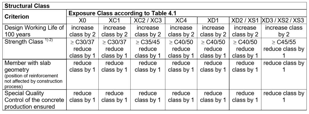
10 !!! d =??? f cd =??? 100 = = = 35kN 35kN L calc = 3.00m M Ed 35kNm where d = h - d s d s = c nom + s /2 s = mm for beams 6 14 mm for slabs V Ed 35kN
11 d = h - d s d s = c nom + s /2 s = mm for beams 6 14 mm for slabs long d s C nom,long etr C nom,etr Δ = 5mm for slabs (A.N.) = 10 mm rest of the elements (A.N.)
12 Δ, ;, ; 10 bond durability
13 Δ, ;, ; 10 bond,
14 Δ, ;, ; 10 bond, where = mm for beams 6 14 mm for slabs 20 mm longitudinal 8 mm transversal
15 Δ, ;, ; 10 durability
16 Δ, ;, ; 10 durability
17
18 Δ, ;, ; 10 durability,
, ;, ; 10 20 ; 10 ; 10, 20 mm Δ 10 (A.N.")
19 LONGITUDINAL REINFORCEMENT Δ TRANSVERSAL REINF. (stirrup), ;, ; ; 10 ; 10, 20 mm Δ 10 (A.N.),,, 22, 22, 20 8 ; 10 ; 10, 10 mm Δ 10 (A.N.),,, 28, 28, 30, OK!!!,,
20 2 d = h d s d s = c nom + s /2 s =20 mm d s = c nom + s /2 =
21 2 d = h d s d s = c nom + s /2 s =20 mm d s = c nom + s /2 = 40 mm d = h d s =
22 2 d = h d s d s = c nom + s /2 s =20 mm d s = c nom + s /2 = 40 mm d = h d s = 260 mm
23 2 f cd f ck c
24 2 f cd f ck = 13,33 N/mm 2 c
25
26 / f yd f yk s

27 / f yd f yk = 435 N/mm 2 s
28 /
29 / = 0,617
30 = 0, / = 0,617
31 = 0, / = 0,617
32 112
33 112 = 0,306
34 112 = 0,306 = 365 mm 2 REINFORCEMENT PROPOSAL?
35
36 112 = 0,306 = 365 mm
37 2 16 d s = c nom + s /2 = d = h d s =, 0,26, 0,0013, 0,04
38 2 16 = 402 mm 2 d s = c nom + s /2 = 38 mm d = h d s = 262 mm, 0,26 =45mm 2 ok!, 0,0013 =51mm 2 ok!, 0,04 = 1800 mm 2 ok!
39 ,,,
40
41
42 min 58 2 ; 30 29
43
44 2.25 design value of the ultimate bond stress where: η 1 η 2 f ctd is a coefficient related to the quality of the bond condition and the position of the bar during concreting (see Figure 8.2): = 1,0 when good conditions are obtained and = 0,7 for all other cases and for bars in structural elements built with slip forms, unless it can be shown that good bond conditions exist - is related to the bar diameter: = 1,0 for φ 32 mm = (132 φ)/100 for φ > 32 mm f ctk0,05 c
: = 1,0 when good conditions are obtained and = 0,7 for all other cases and for bars in structural elements built with slip forms, unless it can be shown that good bond conditions exist - is")
45 2.25 design value of the ultimate bond stress where: η 1 η 2 f ctd is a coefficient related to the quality of the bond condition and the position of the bar during concreting (see Figure 8.2): = 1,0 when good conditions are obtained and = 0,7 for all other cases and for bars in structural elements built with slip forms, unless it can be shown that good bond conditions exist - is related to the bar diameter: = 1,0 for φ 32 mm = (132 φ)/100 for φ > 32 mm f ctk0,05 c 2,25 N/mm 2 =1,00N/mm 2
46 , ,,
47 2,25 N/mm 2, 4 =773 mm ,, =773 mm
48 , max,100 1/3 1 1, 0,18/ ,15 / 0,2
49 , max,100 1/3 1 1, 0,18/ ,15 / 0,2 =0
50 , max,100 1/ A sl =???
51 , max,100 1/ A sl =??? - is the area of the tensile reinforcement, which extends (lbd + d) beyond the section considered
52 , max,100 1/ A sl = 216 = 402 mm 2 - is the area of the tensile reinforcement, which extends (lbd + d) beyond the section considered
53 , max,100 1/ ,035 3/2 1/2 =,
54 , max,100 1/ ,035 3/2 1/2 = 0.403, kn
55 24.03 kn, max,100 1/ kn 0,035 3/2 1/2 = 0.403, kn
56 ,
57 , SHEAR REINFORCEMENT IS REQUIRED min, ;,
58 , SHEAR REINFORCEMENT IS REQUIRED min, ;,
59 CAPACITY OF THE COMPRESSED (CONCRETE) CHORD (V Rd,max ), / cw 1 - is a coefficient taking account of the state of the stress in the compression chord cw =1 for RC elements cw >1 for PC elements - is a strength reduction factor for concrete cracked in shear 1 0, (A.N.) z 0.9d =
60 CAPACITY OF THE COMPRESSED (CONCRETE) CHORD (V Rd,max ), / cw 1 - is a coefficient taking account of the state of the stress in the compression chord cw =1 for RC elements cw >1 for PC elements - is a strength reduction factor for concrete cracked in shear 1 0, (A.N.) z 0.9d = 236 mm
61 CAPACITY OF THE COMPRESSED (CONCRETE) CHORD (V Rd,max ), / Choosing 45 90,
62 CAPACITY OF THE COMPRESSED (CONCRETE) CHORD (V Rd,max ), / Choosing 45 90, kn
63 CAPACITY OF SHEAR REINFORCEMENT (V Rd,s ), Choosing - the cross sectional area of the shear reinforcement or and the spacing of the stirrups From condition,
64 CAPACITY OF SHEAR REINFORCEMENT (V Rd,s ) Diametre of stirrups are imposed () A sw =na s (n= no shear arms!!!) s (spacing)
65 CAPACITY OF SHEAR REINFORCEMENT (V Rd,s ) Diametre of stirrups are imposed () A sw =na s (n= no shear arms!!!) 26? 28? s (spacing)
66 CAPACITY OF SHEAR REINFORCEMENT (V Rd,s ) Diametre of stirrups are imposed () A sw =na s (n= no shear arms!!!) s (spacing) mm 2
67 CAPACITY OF SHEAR REINFORCEMENT (V Rd,s ) mm Diametre of stirrups are imposed () A sw =na s (n= no shear arms!!!) s (spacing) mm 2
68 CAPACITY OF SHEAR REINFORCEMENT (V Rd,s ) mm 2 Reinforcement ratio for shear reinforcement, 0,08 / >(?),
69 CAPACITY OF SHEAR REINFORCEMENT (V Rd,s ) mm 2 Reinforcement ratio for shear reinforcement, 0,08 / 1.439x x10 3 >(?),
70 CAPACITY OF SHEAR REINFORCEMENT (V Rd,s ) mm mm 2 s =
71 CAPACITY OF SHEAR REINFORCEMENT (V Rd,s ) mm mm 2 s = 166 mm
72 CAPACITY OF SHEAR REINFORCEMENT (V Rd,s ), 0,75 1 Choosing s = 150 mm, s,
73 CAPACITY OF SHEAR REINFORCEMENT (V Rd,s ), 0, mm Choosing s = 150 mm, s,
74 CAPACITY OF SHEAR REINFORCEMENT (V Rd,s ), 0, mm Choosing s = 150 mm, kn s,
75 DUCTILITY CONDITION FOR SHEAR REINFORCEMENT,, For a crack at 45 (ctg = 1) 1 1 0,5
76 DUCTILITY CONDITION FOR SHEAR REINFORCEMENT 0,5? <?
77 DUCTILITY CONDITION FOR SHEAR REINFORCEMENT 0, N/mm N/mm 2 OK!
78 DUCTILITY CONDITION FOR SHEAR REINFORCEMENT 0, N/mm N/mm 2 OK!
79 2 ND VARIANT!!! DESIGN OF LONGITUDINAL REINFORCEMENT AND SHEAR REINFORCEMENT USING STIRRUPS AND INCLINED BARS
80 2 ND VARIANT = 367 mm 2 s 3 14 = 462 mm2 d s = c nom + s /2 = 38 mm d = h d s = 262 mm
81 2,25 N/mm 2, 4 =676 mm ,, =676 mm
82 , max,100 1/3 1 1, 0,18/ ,15 / 0,2 =0
83 , max,100 1/3 1 1 A sl = 214 = 308 mm s 0.02
84 , max,100 1/ ,035 3/2 1/2 = 0.401, kn
85 , SHEAR REINFORCEMENT IS REQUIRED min, ;,
86 CAPACITY OF THE COMPRESSED (CONCRETE) CHORD (V Rd,max ), 1 cw 1 - is a coefficient taking account of the state of the stress in the compression chord cw =1 for RC elements cw >1 for PC elements - is a strength reduction factor for concrete cracked in shear 1 0, (A.N.) z 0.9d = 236 mm
87 CAPACITY OF THE COMPRESSED (CONCRETE) CHORD (V Rd,max ), 1 Choosing = 45, kn = 45
88 SHEAR CAPACITY OF ELEMENTS REINFORCED WITH INCLINED BARS, Choosing A sw s - aria of inclined bar distance between inclined bars s = 45 = 45 A sw = 114 = 154 mm 2
89 SHEAR CAPACITY OF ELEMENTS REINFORCED WITH INCLINED BARS Maximum distance between inclined bars, 0, mm Choosing s = 300 mm, 74.4 kn
90 SHEAR CAPACITY OF ELEMENTS REINFORCED WITH INCLINED BARS,, For an inclined bar at 45 and compressed chord of 45 : 0,5 1
91 SHEAR CAPACITY OF ELEMENTS REINFORCED WITH INCLINED BARS 0, N/mm N/mm 2
92 SHEAR CAPACITY ALONG THE INCLINED BAR (V Rd,s ) = = = P/2 P/2 L V Ed 5cm 26 cm V Ed V Rd
93 SHEAR CAPACITY AFTER THE INCLINED BAR (V Rd,s ) Se impune diametrul () etrierului A sw =na s (n= nr ramuri!!!) s (pasul) mm 2
94 SHEAR CAPACITY AFTER THE INCLINED BAR (V Rd,s ) = = = P/2 P/2 L V Ed V Ed V Rd CALCUL = IDEM PARTEA 1! V Ed = IDEM
95 SITUATION WITH DISTRIBUTED LOADS p = 23,33 kn/m, 0, mm L Imposing 6 /19 cm V Rd V Ed V Ed =27,78kN V Ed,??? s
96 SITUATION WITH DISTRIBUTED LOADS p = 23,33 kn/m, 0, mm L Imposing 6 /19 cm V Rd V Ed V ed =27,78kN V Ed,, s 5cm 26 cm


97
10/14/2011. Types of Shear Failure. CASE 1: a v /d 6. a v. CASE 2: 2 a v /d 6. CASE 3: a v /d 2
 V V Types o Shear Failure a v CASE 1: a v /d 6 d V a v CASE 2: 2 a v /d 6 d V a v CASE 3: a v /d 2 d V 1 Shear Resistance Concrete compression d V cz = Shear orce in the compression zone (20 40%) V a =
REINFORCED CONCRETE DESIGN 1. Design of Column (Examples and Tutorials)
") For updated version, please click on http://ocw.ump.edu.my REINFORCED CONCRETE DESIGN 1 Design of Column (Examples and Tutorials) by Dr. Sharifah Maszura Syed Mohsin Faculty of Civil Engineering and Earth
For updated version, please click on http://ocw.ump.edu.my REINFORCED CONCRETE DESIGN 1 Design of Column (Examples and Tutorials) by Dr. Sharifah Maszura Syed Mohsin Faculty of Civil Engineering and Earth
Bending and Shear in Beams
 Bending and Shear in Beams Lecture 3 5 th October 017 Contents Lecture 3 What reinforcement is needed to resist M Ed? Bending/ Flexure Section analysis, singly and doubly reinforced Tension reinforcement,
Department of Mechanics, Materials and Structures English courses Reinforced Concrete Structures Code: BMEEPSTK601. Lecture no. 6: SHEAR AND TORSION
 Budapest University of Technology and Economics Department of Mechanics, Materials and Structures English courses Reinforced Concrete Structures Code: BMEEPSTK601 Lecture no. 6: SHEAR AND TORSION Reinforced
Design of reinforced concrete sections according to EN and EN
 Design of reinforced concrete sections according to EN 1992-1-1 and EN 1992-2 Validation Examples Brno, 21.10.2010 IDEA RS s.r.o. South Moravian Innovation Centre, U Vodarny 2a, 616 00 BRNO tel.: +420-511
DESIGN OF STAIRCASE. Dr. Izni Syahrizal bin Ibrahim. Faculty of Civil Engineering Universiti Teknologi Malaysia
 DESIGN OF STAIRCASE Dr. Izni Syahrizal bin Ibrahim Faculty of Civil Engineering Universiti Teknologi Malaysia Email: iznisyahrizal@utm.my Introduction T N T G N G R h Flight Span, L Landing T = Thread
CE5510 Advanced Structural Concrete Design - Design & Detailing of Openings in RC Flexural Members-
 CE5510 Advanced Structural Concrete Design - Design & Detailing Openings in RC Flexural Members- Assoc Pr Tan Kiang Hwee Department Civil Engineering National In this lecture DEPARTMENT OF CIVIL ENGINEERING
Design of AAC wall panel according to EN 12602
 Design of wall panel according to EN 160 Example 3: Wall panel with wind load 1.1 Issue Design of a wall panel at an industrial building Materials with a compressive strength 3,5, density class 500, welded
Delhi Noida Bhopal Hyderabad Jaipur Lucknow Indore Pune Bhubaneswar Kolkata Patna Web: Ph:
 Serial : IG1_CE_G_Concrete Structures_100818 Delhi Noida Bhopal Hyderabad Jaipur Lucknow Indore Pune Bhubaneswar Kolkata Patna Web: E-mail: info@madeeasy.in Ph: 011-451461 CLASS TEST 018-19 CIVIL ENGINEERING
Detailing. Lecture 9 16 th November Reinforced Concrete Detailing to Eurocode 2
 Detailing Lecture 9 16 th November 2017 Reinforced Concrete Detailing to Eurocode 2 EC2 Section 8 - Detailing of Reinforcement - General Rules Bar spacing, Minimum bend diameter Anchorage of reinforcement
Reinforced Concrete Structures
 Reinforced Concrete Structures MIM 232E Dr. Haluk Sesigür I.T.U. Faculty of Architecture Structural and Earthquake Engineering WG Ultimate Strength Theory Design of Singly Reinforced Rectangular Beams
- Rectangular Beam Design -
 Semester 1 2016/2017 - Rectangular Beam Design - Department of Structures and Material Engineering Faculty of Civil and Environmental Engineering University Tun Hussein Onn Malaysia Introduction The purposes
Assignment 1 - actions
 Assignment 1 - actions b = 1,5 m a = 1 q kn/m 2 Determine action on the beam for verification of the ultimate limit state. Axial distance of the beams is 1 to 2 m, cross section dimensions 0,45 0,20 m
Concrete and Masonry Structures 1 Office hours
 Concrete and Masonry Structures 1 Petr Bílý, office B731 http://people.fsv.cvut.cz/www/bilypet1 Courses in English Concrete and Masonry Structures 1 Office hours Credit receiving requirements General knowledge
Concise Eurocode 2 25 February 2010
 Concise Eurocode 2 25 February 2010 Revisions required to Concise Eurocode 2 (Oct 06 edition) due to revisions in standards, notably Amendment 1 to NA to BS EN 1992-1-1:2004 dated Dec 2009, and interpretations.
Eurocode Training EN : Reinforced Concrete
 Eurocode Training EN 1992-1-1: Reinforced Concrete Eurocode Training EN 1992-1-1 All information in this document is subject to modification without prior notice. No part of this manual may be reproduced,
CRACK FORMATION AND CRACK PROPAGATION INTO THE COMPRESSION ZONE ON REINFORCED CONCRETE BEAM STRUCTURES
 S. Kakay et al. Int. J. Comp. Meth. and Exp. Meas. Vol. 5 No. (017) 116 14 CRACK FORMATION AND CRACK PROPAGATION INTO THE COMPRESSION ZONE ON REINFORCED CONCRETE BEAM STRUCTURES SAMDAR KAKAY DANIEL BÅRDSEN
Design of Reinforced Concrete Beam for Shear
 Lecture 06 Design of Reinforced Concrete Beam for Shear By: Prof Dr. Qaisar Ali Civil Engineering Department UET Peshawar drqaisarali@uetpeshawar.edu.pk 1 Topics Addressed Shear Stresses in Rectangular
Einführung des EC2 in Belgien The introduction of EC2 in Belgium
 Luc Taerwe 1 Einführung des EC2 in Belgien The introduction of EC2 in Belgium Luc Taerwe Univ.-Prof. Dr.-Ing. habil. Luc Taerwe - graduated as civil engineer at Ghent University (1975) where he also obtained
3.2 Reinforced Concrete Slabs Slabs are divided into suspended slabs. Suspended slabs may be divided into two groups:
 Sabah Shawkat Cabinet of Structural Engineering 017 3. Reinforced Concrete Slabs Slabs are divided into suspended slabs. Suspended slabs may be divided into two groups: (1) slabs supported on edges of
Design of Reinforced Concrete Beam for Shear
 Lecture 06 Design of Reinforced Concrete Beam for Shear By: Civil Engineering Department UET Peshawar drqaisarali@uetpeshawar.edu.pk Topics Addressed Shear Stresses in Rectangular Beams Diagonal Tension
DESIGN OF DOWELS FOR SHEAR TRANSFER AT THE INTERFACE BETWEEN CONCRETE CAST AT DIFFERENT TIMES: A CASE STUDY
 DESIGN OF DOWELS FOR SHEAR TRANSFER AT THE INTERFACE BETWEEN CONCRETE CAST AT DIFFERENT TIMES: A CASE STUDY Samayamanthree Mudiyanselage Premasiri Karunarathna 118614J Degree of Master of Engineering in
Seismic Design, Assessment & Retrofitting of Concrete Buildings. fctm. h w, 24d bw, 175mm 8d bl, 4. w 4 (4) 2 cl
 2 cl") Seismic Design, Assessment & Retroitting o Concrete Buildings Table 5.1: EC8 rules or detailing and dimensioning o primary beams (secondary beams: as in DCL) DC H DCM DCL critical region length 1.5h w
Seismic Design, Assessment & Retroitting o Concrete Buildings Table 5.1: EC8 rules or detailing and dimensioning o primary beams (secondary beams: as in DCL) DC H DCM DCL critical region length 1.5h w
Practical Design to Eurocode 2. The webinar will start at 12.30
 Practical Design to Eurocode 2 The webinar will start at 12.30 Course Outline Lecture Date Speaker Title 1 21 Sep Jenny Burridge Introduction, Background and Codes 2 28 Sep Charles Goodchild EC2 Background,
Job No. Sheet No. Rev. CONSULTING Engineering Calculation Sheet
 E N G I N E E R S Consulting Engineers jxxx 1 Material Properties Characteristic strength of concrete, f cu ( 60N/mm 2 ; HSC N/A) 35 N/mm 2 OK Yield strength of longitudinal steel, f y 460 N/mm 2 Yield
DESIGN AND DETAILING OF COUNTERFORT RETAINING WALL
 DESIGN AND DETAILING OF COUNTERFORT RETAINING WALL When the height of the retaining wall exceeds about 6 m, the thickness of the stem and heel slab works out to be sufficiently large and the design becomes
Job No. Sheet No. Rev. CONSULTING Engineering Calculation Sheet. Member Design - Steel Composite Beam XX 22/09/2016
 CONSULTING Engineering Calculation Sheet jxxx 1 Member Design - Steel Composite Beam XX Introduction Chd. 1 Grade 50 more common than Grade 43 because composite beam stiffness often 3 to 4 times non composite
Chapter 8. Shear and Diagonal Tension
 Chapter 8. and Diagonal Tension 8.1. READING ASSIGNMENT Text Chapter 4; Sections 4.1-4.5 Code Chapter 11; Sections 11.1.1, 11.3, 11.5.1, 11.5.3, 11.5.4, 11.5.5.1, and 11.5.6 8.2. INTRODUCTION OF SHEAR
Lecture-04 Design of RC Members for Shear and Torsion
 Lecture-04 Design of RC Members for Shear and Torsion By: Prof. Dr. Qaisar Ali Civil Engineering Department UET Peshawar drqaisarali@uetpeshawar.edu.pk www.drqaisarali.com 1 Topics Addressed Design of
Example 2.2 [Ribbed slab design]
![Example 2.2 [Ribbed slab design]](/thumbs/78/77625473.jpg "Example 2.2 [Ribbed slab design]") Example 2.2 [Ribbed slab design] A typical floor system of a lecture hall is to be designed as a ribbed slab. The joists which are spaced at 400mm are supported by girders. The overall depth of the slab
Example 2.2 [Ribbed slab design] A typical floor system of a lecture hall is to be designed as a ribbed slab. The joists which are spaced at 400mm are supported by girders. The overall depth of the slab
O Dr Andrew Bond (Geocentrix)
") DECODING EUROCODES 2 + 7: DESIGN SG OF FOUNDATIONS O Dr Andrew Bond (Geocentrix) Outline of talk April 2010: the death of British Standards? UK implementation of Eurocodes Verification of strength: limit
DECODING EUROCODES 2 + 7: DESIGN SG OF FOUNDATIONS O Dr Andrew Bond (Geocentrix) Outline of talk April 2010: the death of British Standards? UK implementation of Eurocodes Verification of strength: limit
Practical Design to Eurocode 2
 Practical Design to Eurocode 2 The webinar will start at 12.30 (Any questions beforehand? use Questions on the GoTo Control Panel) Course Outline Lecture Date Speaker Title 1 21 Sep Jenny Burridge Introduction,
Pre-stressed concrete = Pre-compression concrete Pre-compression stresses is applied at the place when tensile stress occur Concrete weak in tension
 Pre-stressed concrete = Pre-compression concrete Pre-compression stresses is applied at the place when tensile stress occur Concrete weak in tension but strong in compression Steel tendon is first stressed
An Analytical Design Method for Steel-Concrete Hybrid Walls Link Peer-reviewed author version
 An Analytical Design Method for Steel-Concrete Hybrid Walls Link Peer-reviewed author version Made available by Hasselt University Library in Document Server@UHasselt Reference (Published version): Plumier,
The European Concrete Platform ASBL, May 2008.
 EUROCODE WORKED EXAMPLES EUROCODE WORKED EXAMPLES The European Concrete Platform ASBL, May 008. All rights reserved. No part of this publication may be reproduced, stored in a retrieval system or transmitted
Job No. Sheet No. Rev. CONSULTING Engineering Calculation Sheet. Member Design - Reinforced Concrete Beam BS8110 v Member Design - RC Beam XX
 CONSULTING Engineering Calculation Sheet E N G I N E E R S Consulting Engineers jxxx 1 Effects From Structural Analysis Design axial force, F (tension -ve and compression +ve) (ensure < 0.1f cu b w h 0
Annex - R C Design Formulae and Data
 The design formulae and data provided in this Annex are for education, training and assessment purposes only. They are based on the Hong Kong Code of Practice for Structural Use of Concrete 2013 (HKCP-2013).
9.5 Compression Members
 9.5 Compression Members This section covers the following topics. Introduction Analysis Development of Interaction Diagram Effect of Prestressing Force 9.5.1 Introduction Prestressing is meaningful when
Roadway Grade = m, amsl HWM = Roadway grade dictates elevation of superstructure and not minimum free board requirement.
 Example on Design of Slab Bridge Design Data and Specifications Chapter 5 SUPERSTRUCTURES Superstructure consists of 10m slab, 36m box girder and 10m T-girder all simply supported. Only the design of Slab
Standardisation of UHPC in Germany
 Standardisation of UHPC in Germany Part II: Development of Design Rules, University of Siegen Prof. Dr.-Ing. Ekkehard Fehling, University of Kassel 1 Overvie Introduction: Work of the Task Group Design
SERVICEABILITY LIMIT STATE DESIGN
 CHAPTER 11 SERVICEABILITY LIMIT STATE DESIGN Article 49. Cracking Limit State 49.1 General considerations In the case of verifications relating to Cracking Limit State, the effects of actions comprise
Appendix K Design Examples
 Appendix K Design Examples Example 1 * Two-Span I-Girder Bridge Continuous for Live Loads AASHTO Type IV I girder Zero Skew (a) Bridge Deck The bridge deck reinforcement using A615 rebars is shown below.
CHAPTER 4. Design of R C Beams
 CHAPTER 4 Design of R C Beams Learning Objectives Identify the data, formulae and procedures for design of R C beams Design simply-supported and continuous R C beams by integrating the following processes
RETAINING WALL ANALYSIS
 GEODOMISI Ltd. Dr. Costas Sachpazis Consulting Company for Tel.: (+30) 20 523827, 20 57263 Fax.:+30 20 5746 Retaining wall Analysis & Design (EN997:2004 App'd by RETAINING WALL ANALYSIS In accordance with
3.5 Analysis of Members under Flexure (Part IV)
") 3.5 Analysis o Members under Flexure (Part IV) This section covers the ollowing topics. Analysis o a Flanged Section 3.5.1 Analysis o a Flanged Section Introduction A beam can have langes or lexural eiciency.
3.5 Analysis o Members under Flexure (Part IV) This section covers the ollowing topics. Analysis o a Flanged Section 3.5.1 Analysis o a Flanged Section Introduction A beam can have langes or lexural eiciency.
RETAINING WALL ANALYSIS
 Retaining Wall Analysis Example (EN997:2004) GEODOMISI Ltd. Dr. Costas Sachpazis Consulting Company for Tel.: (+30) 20 523827, 20 57263 Fax.:+30 20 5746 App'd by RETAINING WALL ANALYSIS In accordance with
CHAPTER 6: ULTIMATE LIMIT STATE
 CHAPTER 6: ULTIMATE LIMIT STATE 6.1 GENERAL It shall be in accordance with JSCE Standard Specification (Design), 6.1. The collapse mechanism in statically indeterminate structures shall not be considered.
Civil Engineering Design (1) Design of Reinforced Concrete Columns 2006/7
 Design of Reinforced Concrete Columns 2006/7") Civil Engineering Design (1) Design of Reinforced Concrete Columns 2006/7 Dr. Colin Caprani, Chartered Engineer 1 Contents 1. Introduction... 3 1.1 Background... 3 1.2 Failure Modes... 5 1.3 Design Aspects...
Civil Engineering Design (1) Design of Reinforced Concrete Columns 2006/7 Dr. Colin Caprani, Chartered Engineer 1 Contents 1. Introduction... 3 1.1 Background... 3 1.2 Failure Modes... 5 1.3 Design Aspects...
Job No. Sheet No. Rev. CONSULTING Engineering Calculation Sheet
 CONSULTING Engineering Calculation Sheet jxxx 1 Effects From Structural Analysis Design axial force, F (tension -ve and compression +ve) (ensure < 0.1f cu b w h 0 kn OK Design shear force, V d 4223 kn
DEFORMATION CAPACITY OF OLDER RC SHEAR WALLS: EXPERIMENTAL ASSESSMENT AND COMPARISON WITH EUROCODE 8 - PART 3 PROVISIONS
 DEFORMATION CAPACITY OF OLDER RC SHEAR WALLS: EXPERIMENTAL ASSESSMENT AND COMPARISON WITH EUROCODE 8 - PART 3 PROVISIONS Konstantinos CHRISTIDIS 1, Emmanouil VOUGIOUKAS 2 and Konstantinos TREZOS 3 ABSTRACT
Job No. Sheet No. Rev. CONSULTING Engineering Calculation Sheet
 CONSULTING Engineering Calculation Sheet E N G I N E E R S Consulting Engineers jxxx 1 Effects From Structural Analysis Design axial force, F (tension -ve and compression +ve) (ensure < 0.1f cu b w h 0
Job No. Sheet No. Rev. CONSULTING Engineering Calculation Sheet. Member Design - RC Two Way Spanning Slab XX
 CONSULTING Engineering Calculation Sheet E N G I N E E R S Consulting Engineers jxxx 1 Material Properties Characteristic strength of concrete, f cu ( 60N/mm 2 ; HSC N/A) 35 N/mm 2 OK Yield strength of
Visit Abqconsultants.com. This program Designs and Optimises RCC Chimney and Foundation. Written and programmed
 Prepared by : Date : Verified by : Date : Project : Ref Calculation Output Design of RCC Chimney :- 1) Dimensions of Chimney and Forces 200 Unit weight of Fire Brick Lining 19000 N/m3 100 Height of Fire
twenty one concrete construction: shear & deflection ARCHITECTURAL STRUCTURES: FORM, BEHAVIOR, AND DESIGN DR. ANNE NICHOLS SUMMER 2014 lecture
 ARCHITECTURAL STRUCTURES: FORM, BEHAVIOR, AND DESIGN DR. ANNE NICHOLS SUMMER 2014 lecture twenty one concrete construction: Copyright Kirk Martini shear & deflection Concrete Shear 1 Shear in Concrete
T2. VIERENDEEL STRUCTURES
 T2. VIERENDEEL STRUCTURES AND FRAMES 1/11 T2. VIERENDEEL STRUCTURES NOTE: The Picture Window House can be designed using a Vierendeel structure, but now we consider a simpler problem to discuss the calculation
STEEL BUILDINGS IN EUROPE. Multi-Storey Steel Buildings Part 10: Technical Software Specification for Composite Beams
 STEEL BUILDINGS IN EUROPE Multi-Storey Steel Buildings Part 10: Technical Software Specification for Composite Beams Multi-Storey Steel Buildings Part 10: Technical Software Specification for Composite
Chapter 4. Test results and discussion. 4.1 Introduction to Experimental Results
 Chapter 4 Test results and discussion This chapter presents a discussion of the results obtained from eighteen beam specimens tested at the Structural Technology Laboratory of the Technical University
Longitudinal strength standard
 (1989) (Rev. 1 199) (Rev. Nov. 001) Longitudinal strength standard.1 Application This requirement applies only to steel ships of length 90 m and greater in unrestricted service. For ships having one or
SPECIFIC VERIFICATION Chapter 5
 As = 736624/(0.5*413.69) = 3562 mm 2 (ADAPT 3569 mm 2, B29, C6) Data Block 27 - Compressive Stresses The initial compressive strength, f ci, is the strength entered in the Material/Concrete input screen.
ANCHORED PILED RETAINING WALL
 10 8 5 0 35.0 25.0 15.0 Soil Profiles -3.0-5 -7.0-10 End of excavation -10-1 -15 Ground Water -15.0-15.0-20 -18.0-25 -30 0 5 10 15 20 25 30 35 40 45 50 55 60 65 70 Soil Profile Layer S.E. (m) c (kn/m³)
Behavior and Modeling of Existing Reinforced Concrete Columns
 Behavior and Modeling of Existing Reinforced Concrete Columns Kenneth J. Elwood University of British Columbia with contributions from Jose Pincheira, Univ of Wisconsin John Wallace, UCLA Questions? What
Note on the moment capacity in a Bubble deck joint
 Tim Gudmand-Høyer Note on the moment capacity in a Bubble deck joint DANMARKS TEKNISKE UNIVERSITET Rapport BYG DTU R-074 2003 ISSN 1601-2917 ISBN 87-7877-137-4 Note on the moment capacity in a Bubble
THEME IS FIRST OCCURANCE OF YIELDING THE LIMIT?
 CIE309 : PLASTICITY THEME IS FIRST OCCURANCE OF YIELDING THE LIMIT? M M - N N + + σ = σ = + f f BENDING EXTENSION Ir J.W. Welleman page nr 0 kn Normal conditions during the life time WHAT HAPPENS DUE TO
Module 6. Shear, Bond, Anchorage, Development Length and Torsion. Version 2 CE IIT, Kharagpur
 Module 6 Shear, Bond, Anchorage, Development Length and Torsion Lesson 15 Bond, Anchorage, Development Length and Splicing Instruction Objectives: At the end of this lesson, the student should be able
Appendix J. Example of Proposed Changes
 Appendix J Example of Proposed Changes J.1 Introduction The proposed changes are illustrated with reference to a 200-ft, single span, Washington DOT WF bridge girder with debonded strands and no skew.
Reinforced concrete structures II. 4.5 Column Design
 4.5 Column Design A non-sway column AB of 300*450 cross-section resists at ultimate limit state, an axial load of 700 KN and end moment of 90 KNM and 0 KNM in the X direction,60 KNM and 27 KNM in the Y
spslab v3.11. Licensed to: STRUCTUREPOINT, LLC. License ID: D2DE-2175C File: C:\Data\CSA A Kt Revised.slb
 X Z Y spslab v3.11. Licensed to: STRUCTUREPOINT, LLC. License ID: 00000-0000000-4-2D2DE-2175C File: C:\Data\CSA A23.3 - Kt Revised.slb Project: CSA A23.3 - Kt Torsional Stiffness Illustration Frame: Engineer:
Improving fire resistance of existing concrete slabs by concrete topping
 Improving fire resistance of existing concrete slabs by concrete topping Is EN 1992-1-2 annex E telling the truth, and can it be used? Tom Molkens StuBeCo bvba, Overpelt - Belgium Structures in Fire Forum
Strengthening of columns with FRP
 with FRP Professor Dr. Björn Täljsten Luleå University of Technology Sto Scandinavia AB 9/12/2013 Agenda Case study Restrained transverse expansion (confinement) Circular and rectangular cross sections
TABLE OF CONTANINET 1. Design criteria. 2. Lateral loads. 3. 3D finite element model (SAP2000, Ver.16). 4. Design of vertical elements (CSI, Ver.9).
. 4. Design of vertical elements (CSI, Ver.9).") TABLE OF CONTANINET 1. Design criteria. 2. Lateral loads. 2-1. Wind loads calculation 2-2. Seismic loads 3. 3D finite element model (SAP2000, Ver.16). 4. Design of vertical elements (CSI, Ver.9). 4-1.
TABLE OF CONTANINET 1. Design criteria. 2. Lateral loads. 2-1. Wind loads calculation 2-2. Seismic loads 3. 3D finite element model (SAP2000, Ver.16). 4. Design of vertical elements (CSI, Ver.9). 4-1.
Flexure: Behavior and Nominal Strength of Beam Sections
 4 5000 4000 (increased d ) (increased f (increased A s or f y ) c or b) Flexure: Behavior and Nominal Strength of Beam Sections Moment (kip-in.) 3000 2000 1000 0 0 (basic) (A s 0.5A s ) 0.0005 0.001 0.0015
EXAMPLE CALCULATIONS DTF / DTS
 MEMO 830 DTF / DTS EXAMPLE CALCULATIONS DESIGN Dato: Siste rev.: Dok. nr.: 19.09.013 5.05.016 K4-10/30E Sign.: Sign.: Control: sss ps CONTENT EXAMPLE CALCULATIONS DTF / DTS EXAMPLE CALCULATIONS DTF / DTS...
Shear at the interface between concrete cast
 Benchmark Example No. 11 Shear at the interface between concrete cast SOFiSTiK 2018 VERiFiCATiON MANUAL DCE-EN11: Shear at the interface between concrete cast VERiFiCATiON MANUAL, Version 2018-7 Software
Figure 1: Representative strip. = = 3.70 m. min. per unit length of the selected strip: Own weight of slab = = 0.
 Example (8.1): Using the ACI Code approximate structural analysis, design for a warehouse, a continuous one-way solid slab supported on beams 4.0 m apart as shown in Figure 1. Assume that the beam webs
CHAPTER 4: BENDING OF BEAMS
 (74) CHAPTER 4: BENDING OF BEAMS This chapter will be devoted to the analysis of prismatic members subjected to equal and opposite couples M and M' acting in the same longitudinal plane. Such members are
Bridge deck modelling and design process for bridges
 EU-Russia Regulatory Dialogue Construction Sector Subgroup 1 Bridge deck modelling and design process for bridges Application to a composite twin-girder bridge according to Eurocode 4 Laurence Davaine
Design of Beams (Unit - 8)
") Design of Beams (Unit - 8) Contents Introduction Beam types Lateral stability of beams Factors affecting lateral stability Behaviour of simple and built - up beams in bending (Without vertical stiffeners)
Design of Beams (Unit - 8) Contents Introduction Beam types Lateral stability of beams Factors affecting lateral stability Behaviour of simple and built - up beams in bending (Without vertical stiffeners)
Design of a Multi-Storied RC Building
 Design of a Multi-Storied RC Building 16 14 14 3 C 1 B 1 C 2 B 2 C 3 B 3 C 4 13 B 15 (S 1 ) B 16 (S 2 ) B 17 (S 3 ) B 18 7 B 4 B 5 B 6 B 7 C 5 C 6 C 7 C 8 C 9 7 B 20 B 22 14 B 19 (S 4 ) C 10 C 11 B 23
SHEAR CAPACITY OF REINFORCED CONCRETE COLUMNS RETROFITTED WITH VERY FLEXIBLE FIBER REINFORCED POLYMER WITH VERY LOW YOUNG S MODULUS
 SHEAR CAPACITY OF REINFORCED CONCRETE COLUMNS RETROFITTED WITH VERY FLEXILE FIER REINFORCED POLYMER WITH VERY LOW YOUNG S MODULUS Hu Shaoqing Supervisor: Susumu KONO ** MEE8165 ASTRACT FRP with low Young
VTU EDUSAT PROGRAMME Lecture Notes on Design of Columns
 VTU EDUSAT PROGRAMME 17 2012 Lecture Notes on Design of Columns DESIGN OF RCC STRUCTURAL ELEMENTS - 10CV52 (PART B, UNIT 6) Dr. M. C. Nataraja Professor, Civil Engineering Department, Sri Jayachamarajendra
Chapter. Materials. 1.1 Notations Used in This Chapter
 Chapter 1 Materials 1.1 Notations Used in This Chapter A Area of concrete cross-section C s Constant depending on the type of curing C t Creep coefficient (C t = ε sp /ε i ) C u Ultimate creep coefficient
EARTHQUAKE SIMULATION TESTS OF BRIDGE COLUMN MODELS DAMAGED DURING 1995 KOBE EARTHQUAKE
 EARTHQUAKE SIMULATION TESTS OF BRIDGE COLUMN MODELS DAMAGED DURING 1995 KOBE EARTHQUAKE J. Sakai 1, S. Unjoh 2 and H. Ukon 3 1 Senior Researcher, Center for Advanced Engineering Structural Assessment and
UNIT-I STRESS, STRAIN. 1. A Member A B C D is subjected to loading as shown in fig determine the total elongation. Take E= 2 x10 5 N/mm 2
 UNIT-I STRESS, STRAIN 1. A Member A B C D is subjected to loading as shown in fig determine the total elongation. Take E= 2 x10 5 N/mm 2 Young s modulus E= 2 x10 5 N/mm 2 Area1=900mm 2 Area2=400mm 2 Area3=625mm
Tower Cranes & Foundations The Interface & CIRIA C654 Stuart Marchand C.Eng. FICE FIStructE Director Wentworth House Partnership
 Tower Cranes & Foundations The Interface & CIRIA C654 Stuart Marchand C.Eng. FICE FIStructE Director Wentworth House Partnership EXAMPLES OF TOWER CRANE FOUNDATION TYPES Rail mounted Pad Base Piled Base
CONSULTING Engineering Calculation Sheet. Job Title Member Design - Reinforced Concrete Column BS8110
 E N G I N E E R S Consulting Engineers jxxx 1 Job Title Member Design - Reinforced Concrete Column Effects From Structural Analysis Axial force, N (tension-ve and comp +ve) (ensure >= 0) 8000kN OK Major
Sabah Shawkat Cabinet of Structural Engineering Walls carrying vertical loads should be designed as columns. Basically walls are designed in
 Sabah Shawkat Cabinet of Structural Engineering 17 3.6 Shear walls Walls carrying vertical loads should be designed as columns. Basically walls are designed in the same manner as columns, but there are
 mportant nstructions to examiners: ) The answers should be examined by key words and not as word-to-word as given in the model answer scheme. ) The model answer and the answer written by candidate may
UNIVERSITÀ DEGLI STUDI DI PADOVA DIPARTIMENTO DI INGEGNERIA CIVILE, EDILE ED AMBIENTALE CORSO DI LAUREA MAGISTRALE IN INGEGNERIA CIVILE
 UNIVERSITÀ DEGLI STUDI DI PADOVA DIPARTIMENTO DI INGEGNERIA CIVILE, EDILE ED AMBIENTALE CORSO DI LAUREA MAGISTRALE IN INGEGNERIA CIVILE Tesi di laurea Magistrale in Ingegneria Civile Curriculum Strutture
KINGS COLLEGE OF ENGINEERING DEPARTMENT OF MECHANICAL ENGINEERING QUESTION BANK. Subject code/name: ME2254/STRENGTH OF MATERIALS Year/Sem:II / IV
 KINGS COLLEGE OF ENGINEERING DEPARTMENT OF MECHANICAL ENGINEERING QUESTION BANK Subject code/name: ME2254/STRENGTH OF MATERIALS Year/Sem:II / IV UNIT I STRESS, STRAIN DEFORMATION OF SOLIDS PART A (2 MARKS)
Associate Professor. Tel:
 DEPARTMENT OF CIVIL ENGINEERING IIT DELHI Dr. Suresh Bhalla Associate Professor Tel: 2659-1040 Email: Sbhalla@civil.iitd.ac.in FOUNDATIONS Geotechnical Engineer Structural Engineer Location and depth criteria
CHAPTER 4. Stresses in Beams
 CHAPTER 4 Stresses in Beams Problem 1. A rolled steel joint (RSJ) of -section has top and bottom flanges 150 mm 5 mm and web of size 00 mm 1 mm. t is used as a simply supported beam over a span of 4 m
STRUCTURAL ANALYSIS CHAPTER 2. Introduction
 CHAPTER 2 STRUCTURAL ANALYSIS Introduction The primary purpose of structural analysis is to establish the distribution of internal forces and moments over the whole part of a structure and to identify
Analysis of the horizontal bearing capacity of a single pile
 Engineering manual No. 16 Updated: 07/2018 Analysis of the horizontal bearing capacity of a single pile Program: Soubor: Pile Demo_manual_16.gpi The objective of this engineering manual is to explain how
MODELLING NON-LINEAR BEHAVIOUR OF STEEL FIBRE REINFORCED CONCRETE
 6th RILEM Symposium on Fibre-Reinforced Concretes (FRC) - BEFIB - September, Varenna, Italy MODELLING NON-LINEAR BEHAVIOUR OF STEEL FIBRE REINFORCED CONCRETE W. A. Elsaigh, J. M. Robberts and E.P. Kearsley
1 Spread footing: Pole_7 Number: 1
 1 Spread footing: Pole_7 Number: 1 1.1 Basic data 1.1.1 Assumptions Geotechnic calculations according to : EN 1997-1:2008 Concrete calculations according to : EN 1992-1-1/BFS 2011:10 EKS8 Shape selection
CIVIL DEPARTMENT MECHANICS OF STRUCTURES- ASSIGNMENT NO 1. Brach: CE YEAR:
 MECHANICS OF STRUCTURES- ASSIGNMENT NO 1 SEMESTER: V 1) Find the least moment of Inertia about the centroidal axes X-X and Y-Y of an unequal angle section 125 mm 75 mm 10 mm as shown in figure 2) Determine
Mechanics of Structure
 S.Y. Diploma : Sem. III [CE/CS/CR/CV] Mechanics of Structure Time: Hrs.] Prelim Question Paper Solution [Marks : 70 Q.1(a) Attempt any SIX of the following. [1] Q.1(a) Define moment of Inertia. State MI
Lap splice length and details of column longitudinal reinforcement at plastic hinge region
 Lap length and details of column longitudinal reinforcement at plastic hinge region Hong-Gun Park 1) and Chul-Goo Kim 2) 1), 2 Department of Architecture and Architectural Engineering, Seoul National University,
Practical Design to Eurocode 2
 Practical Design to Eurocode 2 The webinar will start at 12.30 (I m happy to field individual questions beforehand Use Questions on the shown Control Panel) Course Outline Lecture Date Speaker Title 1
Displacement-based methods EDCE: Civil and Environmental Engineering CIVIL Advanced Earthquake Engineering
 Displacement-based methods EDCE: Civil and Environmental Engineering CIVIL 706 - Advanced Earthquake Engineering EDCE-EPFL-ENAC-SGC 2016-1- Content! Link to force-based methods! Assumptions! Reinforced