PDA Workshop: Stresses, Integrity, Energy and Capacity
|
|
|
- Elizabeth McCormick
- 6 years ago
- Views:
Transcription


1 PDA Workshop: Stresses, Integrity, Energy and Capacity Ir Richard C L Yu IEM 2 Sep 2013
2


3 Dynamic Pile Monitoring For each blow determine Pile driving stresses Pile integrity Hammer performance Capacity at time of testing Working through some examples Stresses Outline Compression, Tension, Bottom Pile Integrity Beta Examples Hammer Performance and Energy Measurements Capacity Methods - RSP, RMX, RSU
 Maximum at gage")

4 Dynamic pile-top measurements provide information throughout pile length and resistance effect FMX, CSX = FMX/A Force (Stress) Maximum at gage location FMX = ε av E A ; CSX = FMX/A or ε av E CSI is the individual high gages reading Strain transducer Ensure that pile top is not overstressed

5 Compressive Stress at the Sensors BN595; yielding Pile force at any location From this morning: Downwards traveling waves from the hammer combine with the upward traveling wave reflected at L/c t = 0 L/c 2L/c L Downward Wave Upward Wave

6 CTN, TSN Maximum Computed Tension force in first period 2L/c after impact CTN = F (t 2 ) + F (t 3 ) min where t 1 <t 3 <t 2 TSN = CTN / A Related: CTX, TSX max. computed tension stress over complete record. +C -T Tension Stress Calculation Wave-Up toe top t 3 Point of max tension Tension Stress Distribution Max. Tension Wave Up
7 CTX, TSX Maximum Computed Tension force (stress) throughout record considering downward tension wave. W d, max-tension + W u, min-comp. CTX = Max CTN TSX = CTX / A -T +C Tension Stress Calculation Wave-Down 2L/c Max. Tension Wave Down Min. Comp. Wave Up


8 CFB, CSB Computed Force at Pile Base CFB CSB = R toe = F t 2 + F t 1 - R shaft = CFB / A F To avoid overstressing at bottom when driving to hard bearing layer F CF B
 - prestress Tension : prestress + (50% of t.")
9 Max CFB is with a time delay due to toe quake CFB = RTL SFT = WD1 + WU2 SFT = = 3456 Codes: Allowable Driving Stresses Steel piles 90% of yield strength for steel Concrete piles Compression: (85% of c.strength) - prestress Tension : prestress + (50% of t.strength) Tension (RR): 70% of yield of reinforcement
 LTD The extent of the damage is")
10 Stresses Outline Compression, Tension, Bottom Pile Integrity Beta Examples Hammer Performance and Energy Measurements Capacity Methods - RSP, RMX, RSU Pile Damage: BTA, LTD Pile damage causes a tension reflection before 2L/c The time at which the tension reflection arrives at the gage location indicates the distance to the damage: LTD = t damage (c / 2) LTD The extent of the damage is quantified with the damage factor BTA ( β )
/(F d,1 - F u,1 ) Z 2 F d,2 F u,1 is the reflection wave that indicates the extent of the impedance reduction")
11 Length to damage or damage location Impedance Reduction Approximate Solution no Skin Friction Z 1 F d,1 F u,1 β = Z 2 / Z 1 β = (F d,1 + F u,1 )/(F d,1 - F u,1 ) Z 2 F d,2 F u,1 is the reflection wave that indicates the extent of the impedance reduction (damage)
12 t 1 F d,1 = ½(F t1 +Zv t1 )= 2863 t 3 F u,1 = ½(F t3 -Zv t3 ) = -650 Beta = { (-650) } / {2863 (-650) } = 0.63 BTA interpretation Integrity - BTA method for uniform piles Looks for local decrease in wave-up β < 80 major damage β < 60 complete break Possible false causes purposely non-uniform pile bending, noise, phase (VT) wrong 2L/c (2 x length / wavespeed) Soils resistance unloading for long friction piles ALWAYS confirm by visually look at data top break toe

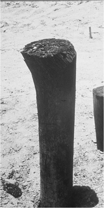
13 26m long Steel Pipe Pile


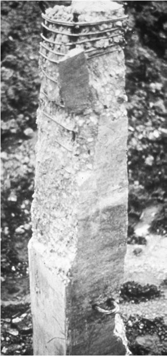
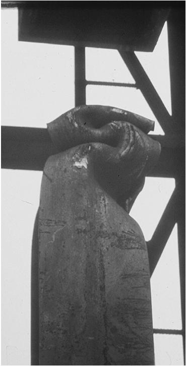
14 Good pile square prestressed concrete piles, about 24m long. Damaged pile Static Bending + Dynamic Stresses


15 large bending force between F1 and F2 Usually from hammer misalignment Bending stresses Difference between F1 and F2
16 Stresses Outline Compression, Tension, Bottom Pile Integrity Beta Examples Energy Measurements Capacity Methods - RSP, RMX, RSU Energy Why is it important? Contractor productivity To install pile to design depth (capacity) Quality control tool (blow count criteria)
 (ideal case, no losses) v i =")

17 PE = WH KE = ½ m v i 2 m = W/g v i = (2gH) (ideal case, no losses) v i = (2gH) e e = efficiency, <1 Can be measured with HPA or proximity switches?

 ETR = EMX /")
 2-0.")

18 From this morning Work = Force x distance = F x EMX = F d x = F d x (dt/dt) = F v d t Energy EMX = maximum of E ( t ) ETR = EMX / (max hammer rated E) STK = ½*g*( T/2 ) 2-0.1(m) ; STK is open end Diesel hammer stroke; T is time between blows ETH = EMX (Wr x STK) diesels only
19 F+ Rebound F+ V+ V- Energy from hammer to pile EMX Energy from pile to hammer DMX E (t) = F v dt Temp. Compression = DMX - DFN DFN Net measured efficiencies (steel piles) 0% 20% 40% 60% 80% 100% 60% hydraulic drop hammers 100% 40% air or steam hammers 70% 30% diesel hammers 60% 20% cabled drop hammers 80% Efficiencies on concrete piles are lower ~ 10%

20
21 Effects of diesel hammer pre-ignition on energy transfer: Stresses Outline Compression, Tension, Bottom Pile Integrity Beta Examples Energy Measurements Capacity Methods - RSP, RMX, RSU
22 From this morning Total Resistance Sum of downward wave at impact and upward wave at toe reflection Case Method Case damping factor applied to toe velocity Rs = (1-Jc)F d,1 + (1+Jc)F u,2 Case Method Static Capacity 5,450 kn 5.75 m/s 5,550 kn 0.0 m/s t 1 t2 RTL = WD1 +WU2 ~ (5550/2) = 8225 R static = RTL J C [2F d1 RTL] R static = (2* ) R Static = = 7155 kn

23 RMX - RXi Calculates R static at all times after the first velocity peak Selects the maximum R static for J C = i 2L/c t 1 t 2
24 RSU, RUI Case Method Capacity Corrected for Early Unloading What Case Damping Factor to choose? Almost always, we choose damping factor based on correlation with CAPWAP or static load test. J typically varies between 0.4 for clean sands and 1.0 for clays.


25 An Example: PDA Capacity Results End of Driving PDA Capacity Results Restrike after 1 month
 One test result is worth a thousand expert opinions Werner Von Braun Father of the Saturn V rocket")
26 Summary Compression and Tension Stress Measured near top Calculated elsewhere in the pile Integrity - Beta is calculated in real time Energy - PDA can measure energy transferred to pile Capacity The Case Method provides many real time estimates of capacity (EOD or Res) One test result is worth a thousand expert opinions Werner Von Braun Father of the Saturn V rocket END
BACKGROUND AND INTRODUCTION
 WAVE MECHANICS As applied to pile testing 1 BACKGROUND AND INTRODUCTION Wave Mechanics 2 1 HISTORIC TOOLS AND MATERIALS Timber piles Drop Hammers 10 Days for the Romans to build the bridge over the Rhine
Dynamic Pile Testing ASTM D4945
 Dynamic Pile Testing ASTM D4945 Pile Driving Analyzer Garland Likins, Pile Dynamics, Inc. 2011 PDCA Professor s Institute Why test driven piles? Public assured of safe foundation (bridges, buildings, etc.)
This document downloaded from vulcanhammer.net vulcanhammer.info Chet Aero Marine
 This document downloaded from vulcanhammer.net vulcanhammer.info Chet Aero Marine Don t forget to visit our companion site http://www.vulcanhammer.org Use subject to the terms and conditions of the respective
CAPWAP Introduction. 2016, Pile Dynamics, Inc. CAPWAP is a registered trademark of Pile Dynamics, Inc. Load (kn) Displacement (mm) Pile Top Bottom
 Displacement (mm) Pile Top Bottom") CAPWAP Introduction Load (kn) 0.0 1000.0 2000.0 3000.0 4000.0 0.00 Pile Top Bottom Displacement (mm) 5.00 10.00 Ru = Rs = Rb = Dy = Dx = 3425.2 kn 1458.6 kn 1966.6 kn 18.8 mm 18.8 mm 15.00 20.00 2016,
CAPWAP Introduction Load (kn) 0.0 1000.0 2000.0 3000.0 4000.0 0.00 Pile Top Bottom Displacement (mm) 5.00 10.00 Ru = Rs = Rb = Dy = Dx = 3425.2 kn 1458.6 kn 1966.6 kn 18.8 mm 18.8 mm 15.00 20.00 2016,
Interpretation of Pile Integrity Test (PIT) Results
 Results") Annual Transactions of IESL, pp. 78-84, 26 The Institution of Engineers, Sri Lanka Interpretation of Pile Integrity Test (PIT) Results H. S. Thilakasiri Abstract: A defect present in a pile will severely
Annual Transactions of IESL, pp. 78-84, 26 The Institution of Engineers, Sri Lanka Interpretation of Pile Integrity Test (PIT) Results H. S. Thilakasiri Abstract: A defect present in a pile will severely
CAPWAP rules Important!
 CAPWAP rules Important! Unit friction < 4 ksf (200 kpa ) for most soils QT (+TG) < Dmax, toe to assure activation QS < 0.2 inch (5 mm ) usually 0.1 inch; 2.5 mm SS, ST < 0.4 s/ft (1.3 s/m ) if higher,
Understanding Dynamic Pile Testing and Driveability
 008-015 understand dynamic 5/30/06 5:10 PM Page 8 Understanding Dynamic Pile Testing and Driveability... By: Engr. Dr Sam Ming Tuck MIEM, P.Eng INTRODUCTION Traditionally, piles are static load tested
Congreso Internacional de Fundaciones Profundas de Bolivia Santa Cruz, Bolivia, 12 al 15 de Mayo de 2015 Day 1: Software Demonstrations
 Applications of Stress Wave Theory to Deep Foundations with an Emphasis on The Wave Equation (GRLWEAP) Congreso Internacional de Fundaciones Profundas de Bolivia Santa Cruz, Bolivia, 12 al 15 de Mayo de
vulcanhammer.info the website about Vulcan Iron Works Inc. and the pile driving equipment it manufactured Terms and Conditions of Use:
 this document downloaded from vulcanhammer.info the website about Vulcan Iron Works Inc. and the pile driving equipment it manufactured Terms and Conditions of Use: All of the information, data and computer
Lesson 25. Static Pile Load Testing, O-cell, and Statnamic. Reference Manual Chapter 18
 Lesson 25 Static Pile Load Testing, O-cell, and Statnamic Reference Manual Chapter 18 STATIC LOAD TESTING Most accurate method to determine static pile capacity Perform at design or construction stage
ASD and LRFD Methods Codes and Economics of Dynamic Testing ASTM D4945
 ASD and LRFD Methods Codes and Economics of Dynamic Testing ASTM D4945 Load Testing. Static Load Testing ASTM D1143 Deadload Testing React. Piles/Anchors Static Load Tests are the standard Costly: Need
Additional Pile Design Considerations
 Additional Pile Design Considerations PDCA 2015 Professor Driven Pile Institute Patrick Hannigan GRL Engineers, Inc. What Are Additional Pile Design Considerations? Time Dependent Soil Strength Changes
vulcanhammer.info the website about Vulcan Iron Works Inc. and the pile driving equipment it manufactured Terms and Conditions of Use:
 this document downloaded from vulcanhammer.info the website about Vulcan Iron Works Inc. and the pile driving equipment it manufactured Terms and Conditions of Use: All of the information, data and computer
Improving site specific modified driving formulae using high frequency displacement monitoring
 Proc. 20 th NZGS Geotechnical Symposium. Eds. GJ Alexander & CY Chin, Napier Improving site specific modified driving formulae using high frequency displacement monitoring R Damen Brian Perry Civil, Auckland,
CPT Pore Water Pressure Correlations with PDA to Identify Pile Drivability Problem
 CPT Pore Water Pressure Correlations with PDA to Identify Pile Drivability Problem Fauzi Jarushi, Paul Cosentino, Edward Kalajian, Hadeel Dekhn Abstract At certain depths during large diameter displacement
Maximum Envelope of Lateral Resistance through Dynamic Increasing Energy Test in Piles
 Maximum Envelope of Lateral Resistance through Dynamic Increasing Energy Test in Piles R.M. Valverde, F. Massad Abstract. The traditional dynamic load test, based on the one-dimensional wave propagation
LOAD RESISTANCE FACTOR DESIGN (LRFD) FOR DRIVEN PILES BASED ON DYNAMIC METHODS WITH ASSESSMENT OF SKIN AND TIP RESISTANCE FROM PDA SIGNALS
 FOR DRIVEN PILES BASED ON DYNAMIC METHODS WITH ASSESSMENT OF SKIN AND TIP RESISTANCE FROM PDA SIGNALS") LOAD RESISTANCE FACTOR DESIGN (LRFD) FOR DRIVEN PILES BASED ON DYNAMIC METHODS WITH ASSESSMENT OF SKIN AND TIP RESISTANCE FROM PDA SIGNALS By ARIEL PEREZ PEREZ A THESIS PRESENTED TO THE GRADUATE SCHOOL
LOAD RESISTANCE FACTOR DESIGN (LRFD) FOR DRIVEN PILES BASED ON DYNAMIC METHODS WITH ASSESSMENT OF SKIN AND TIP RESISTANCE FROM PDA SIGNALS By ARIEL PEREZ PEREZ A THESIS PRESENTED TO THE GRADUATE SCHOOL
Literature review Quasi-static and Dynamic pile load tests
 Literature review Quasi-static and Dynamic pile load tests --------N.Q.HUY-------- Table of contents: I. Introduction.3 II. Quasi static pile load test methods...4 2.1. Quasi static pile load test procedures
PILE SETUP LA-1 EXPERIENCE. Ching-Nien Tsai, P.E.
 PILE SETUP LA-1 EXPERIENCE Ching-Nien Tsai, P.E. Bayou Lafourche Mississippi River GEOTECHNICAL INVESTIGATION PROGRAM 102 CPT soundings Depths from 100 feet to 200 feet 118 borings Depths from
Views on Accuracy of Tests and Analyses
 Piling & Deep Foundations Asia 29 Workshop A, July 13, 29 Views on Accuracy of Tests and Analyses Bengt H. Fellenius ======================================================================================================================
Standard Test Method for High-Strain Dynamic Testing of Deep Foundations 1
 Designation: D4945 12 Standard Test Method for High-Strain Dynamic Testing of Deep Foundations 1 This standard is issued under the fixed designation D4945; the number immediately following the designation
EVALUATION OF LOAD TESTS FOR DRIVEN PILES FOR THE ALABAMA DEPARTMENT OF TRANSPORTATION. Jacob Wayne Hill
 EVALUATION OF LOAD TESTS FOR DRIVEN PILES FOR THE ALABAMA DEPARTMENT OF TRANSPORTATION Except where reference is made to the work of others, the work described in this thesis is my own or was done in collaboration
Comparison of Static and Dynamic Pile Load Tests at Thi Vai International Port in Viet Nam
 Comparison of Static and Dynamic Pile Load Tests at Thi Vai International Port in Viet Nam Le Phan Ta, Ph.D student, Graduate School of Kanazawa University, Japan (HCMC University of Architecture, Viet
Bored Sockets in weathered Basalt
 Bored Sockets in weathered Basalt L. Maertens Manager Engineering Department Besix, Belgium Associate Professor Catholic University Leuven Keywords: sockets, open-end piles, tensile piles, basalt ABSTRACT:
DESIGNING FOR DOWNDRAG ON UNCOATED AND BITUMEN COATED PILES
 DESIGNING FOR DOWNDRAG ON UNCOATED AND BITUMEN COATED PILES Jean-Louis BRIAUD, PhD, PE President of ISSMGE Professor and Holder of the Buchanan Chair Texas A&M University Piling and Deep Foundations Middle
Verification of Signal Matching Analysis of Pile Driving Using a Finite Difference Based Continuum Numerical Method
 Verification of Signal Matching Analysis of Pile Driving Using a Finite Difference Based Continuum Numerical Method Shahram Feizee Masouleh 1, Kazem Fakharian 1,* Received 2 September 27; accepted 9 June
S E C T I O N 1 2 P R O D U C T S E L E C T I O N G U I D E - H E L I C A L S C R E W P I L E F O U N D A T I O N S
 1. P R O D U C T S E L E C T I O N G U I D E - H E L I C A L S C R E W P I L E F O U N D A T I O N S Helical foundation pile includes a lead and extension(s). The lead section is made of a central steel
A PRACTICAL METHOD FOR IMPROVED IMPLEMENTATION OF PILE DRIVING FORMULA
 A PRACTICAL METHOD FOR IMPROVED IMPLEMENTATION OF PILE DRIVING FORMULA A thesis submitted in fulfilment of the requirements for the degree of Master of Engineering Hamayon Tokhi B.Eng. School of Civil,
INTI COLLEGE MALAYSIA
 EGC373 (F) / Page 1 of 5 INTI COLLEGE MALAYSIA UK DEGREE TRANSFER PROGRAMME INTI ADELAIDE TRANSFER PROGRAMME EGC 373: FOUNDATION ENGINEERING FINAL EXAMINATION : AUGUST 00 SESSION This paper consists of
vulcanhammer.info the website about Vulcan Iron Works Inc. and the pile driving equipment it manufactured Terms and Conditions of Use:
 this document downloaded from vulcanhammer.info the website about Vulcan Iron Works Inc. and the pile driving equipment it manufactured Terms and Conditions of Use: All of the information, data and computer
INTRODUCTION TO STATIC ANALYSIS PDPI 2013
 INTRODUCTION TO STATIC ANALYSIS PDPI 2013 What is Pile Capacity? When we load a pile until IT Fails what is IT Strength Considerations Two Failure Modes 1. Pile structural failure controlled by allowable
Technical Note 16 Equivalent Static Method
 Technical Note 16 Equivalent Static Method Contents Technical Note 21 -... 1 1 Introduction... 1 2 Operational Strain in the Pipeline... 2 3 Seismicity... 2 4 Vertical Uplift... 3 5 Vertical Bearing...
Type approval granted by the Finnish Ministry of the Environment
 RR Piling Manual 2 Type approval granted by the Finnish Ministry of the Environment 2..02. RR Piling Manual 1. General This manual deals with impact-driven RR piles. It is an abridgement of the RR Piling
Assessment of Calculation Procedures for Piles in Clay based on Static Loading Tests Anders Hust Augustesen
 Assessment of Calculation Procedures for Piles in Clay based on Static Loading Tests By Anders Hust Augustesen 1 Agenda Presentation of calculation procedures Basis for the evaluation of the calculation
THEME IS FIRST OCCURANCE OF YIELDING THE LIMIT?
 CIE309 : PLASTICITY THEME IS FIRST OCCURANCE OF YIELDING THE LIMIT? M M - N N + + σ = σ = + f f BENDING EXTENSION Ir J.W. Welleman page nr 0 kn Normal conditions during the life time WHAT HAPPENS DUE TO
Technical information CONCRETE / SOLID STONE. Reaction resin mortar, epoxy-acrylate-based with styrene USAGE INSTRUCTIONS
 CONCRETE / SOLID STONE USAGE 1. AREAS OF APPLICATION Heavy load-carrying attachments in solid stone, concrete, porous concrete and light concrete Suitable for attachment points close to the edge, since
Toe Protection for H-piles on Sloping Bedrock at Rainy River
 Toe Protection for H-piles on Sloping Bedrock at Rainy River Jon E. Bischoff, Bengt H. Fellenius, Richard E. Riker Proceedings of Deep Foundations Institute Annual Meeting, Pittsburgh October 18-20, 1993
Use of Ultra-High Performance Concrete in Geotechnical and Substructure Applications
 Use of Ultra-High Performance Concrete in Geotechnical and Substructure Applications i PI: Muhannad Suleiman Co-PI: Sri Sritharan Graduate Research Assistant: Thomas L. Vande Voort January 13, 29 IOWA
Implementation of Pile Setup in the LRFD Design of Driven Piles in Louisiana
 Implementation of Pile Setup in the LRFD Design of Driven Piles in Louisiana Md. Nafiul Haque (Ph.D. Candidate) Murad Y. Abu-Farsakh, Ph.D., P.E. March 1, 2016 Louisiana Transportation Conference OUTLINE
DESIGN AND DETAILING OF COUNTERFORT RETAINING WALL
 DESIGN AND DETAILING OF COUNTERFORT RETAINING WALL When the height of the retaining wall exceeds about 6 m, the thickness of the stem and heel slab works out to be sufficiently large and the design becomes
1 Input data. Profis Anchor Company: Specifier: Address: Phone I Fax: Page: Project: Sub-Project I Pos. No.
 1 Specifier's comments: Check of Existing Base plate (B6)- According to max. forces on Node No. 11979, LC 1.4(D.L.+WX) 1 Input data Anchor type and diameter: HIT-HY 200 + HIT-V-F (8.8) M27 Seismic/Filling
1 Input data. Profis Anchor Company: Specifier: Address: Phone I Fax: Page: Project: Sub-Project I Pos. No.
 1 Specifier's comments: Design of Typical Baseplate B1 according to Max. forces in Node No. (5984), LC19 (1.2D+1.6S+0.8WY CASE B) 1 Input data Anchor type and diameter: HIT-HY 200 + HIT-V (8.8) M24 Seismic/Filling
cyclic loading in Germany
 Note to actual al design of micropiles under axial cyclic loading in Germany according to DIN 1054 and further guidelines Jennifer Kleih 9th International Workshop on Micropiles London 13th May 2009 Outline
Special edition paper
 Development of New Aseismatic Structure Using Escalators Kazunori Sasaki* Atsushi Hayashi* Hajime Yoshida** Toru Masuda* Aseismatic reinforcement work is often carried out in parallel with improvement
Design and Construction of Large Diameter Impact Driven Pipe Pile Foundations New East Span San Francisco-Oakland Bay Bridge
 Missouri University of Science and Technology Scholars' Mine International Conference on Case Histories in Geotechnical Engineering (2004) - Fifth International Conference on Case Histories in Geotechnical
Discussion: behaviour of jacked and driven piles in sandy soil
 Title Discussion: behaviour of jacked and driven piles in sandy soil Author(s) Yang, J; Tham, LG; Lee, PKK; Chan, ST; Yu, F Citation Géotechnique, 27, v. 7 n., p. 47-478 Issued Date 27 URL http://hdl.handle.net/1722/7161
Summary and Review of Part II of the Symposium on Pile Foundations
 Summary and Review of Part II of the Symposium on Pile Foundations G. A. LEONARDS, Purdue University PILE FOUNDATIONS share with cellular cofferdams the distinction of yielding most reluctantly to the
INCREASE IN PILE CAPACITY WITH TIME IN MISSOURI RIVER ALLUVIUM
 INCREASE IN PILE CAPACITY WITH TIME IN MISSOURI RIVER ALLUVIUM Paul J. Axtell Jacob W. Owen Scott D. Vollink U.S. Army Corps of Engineers U.S. Army Corps of Engineers U.S. Army Corps of Engineers Kansas
Liquefaction Induced Negative Skin Friction from Blast-induced Liquefaction Tests with Auger-cast Piles
 6 th International Conference on Earthquake Geotechnical Engineering 1-4 November 2015 Christchurch, New Zealand Liquefaction Induced Negative Skin Friction from Blast-induced Liquefaction Tests with Auger-cast
Delhi Noida Bhopal Hyderabad Jaipur Lucknow Indore Pune Bhubaneswar Kolkata Patna Web: Ph:
 Serial : IG1_CE_G_Concrete Structures_100818 Delhi Noida Bhopal Hyderabad Jaipur Lucknow Indore Pune Bhubaneswar Kolkata Patna Web: E-mail: info@madeeasy.in Ph: 011-451461 CLASS TEST 018-19 CIVIL ENGINEERING
VMS-GeoMil. Background
 Background When using a drilling rig for cone penetration testing, a mechanical clamp can be mounted to the drilling head (by means of a special transition piece). The depth than can be achieved depends
Analysis of a single pile settlement
 Engineering manual No. 14 Updated: 06/2018 Analysis of a single pile settlement Program: Pile File: Demo_manual_14.gpi The objective of this engineering manual is to explain the application of the GEO
Work and Energy continued
 Chapter 6 Work and Energy continued 6.2 The Work-Energy Theorem and Kinetic Energy Chapters 1 5 Motion equations were been developed, that relate the concepts of velocity, speed, displacement, time, and
Clayey sand (SC)
") Pile Bearing Capacity Analysis / Verification Input data Project Task : PROJECT: "NEW STEAM BOILER U-5190 Part : A-1 Descript. : The objective of this Analysis is the Pile allowable bearing Capacity Analysis
Pile Bearing Capacity Analysis / Verification Input data Project Task : PROJECT: "NEW STEAM BOILER U-5190 Part : A-1 Descript. : The objective of this Analysis is the Pile allowable bearing Capacity Analysis
THE STRUCTURAL DESIGN OF PILE FOUNDATIONS BASED ON LRFD FOR JAPANESE HIGHWAYS
 THE STRUCTURAL DESIGN OF PILE FOUNDATIONS BASED ON LRFD FOR JAPANESE HIGHWAYS Hideaki Nishida 1,Toshiaki Nanazawa 2, Masahiro Shirato 3, Tetsuya Kohno 4, and Mitsuaki Kitaura 5 Abstract One of the motivations
OP-023. INTERPRETATION OF INSTRUMENTED TEST PILE RESULT
 INTERPRETATION OF INSTRUMENTED TEST PILE RESULT Page 1 of 9 WORK INSTRUCTIONS FOR ENGINEERS GSJ Compiled by : Checked by KYW : LSS Approved by : OP-23. INTERPRETATION OF INSTRUMENTED TEST PILE RESULT INTERPRETATION
Implementation of Laterally Loaded Piles in Multi-Layer Soils
 Implementation of Laterally Loaded Piles in Multi-Layer Soils JTRP SPR- 3261 Final SAC meeting SAC members Mir Zaheer and Keith Hoernschemeyer Purdue University Introduction Analysis developed for the
50 ksi Steel H-pile Capacity
 50 ksi Steel H-pile Capacity FINAL REPORT June 30, 2015 Kent A Harries, PhD, FACI, FIIFC, PEng Jeen-Shang Lin, ScD, PE Marwa Hasanzoi, MSCE COMMONWEALTH OF PENNSYLVANIA DEPARTMENT OF TRANSPORTATION CONTRACT
APPENDIX G I-BEAM SUMMARIES 0.6-IN. STRAND G-1
 APPENDIX G I-BEAM SUMMARIES.6-IN. STRAND G-1 Concrete Compressive Strength Embedment Length(L e ) Span Failure Mode Maximum Load Maximum Shear Maximum Moment Maximum Deflection attained Rebound after complete
Numerical Modelling of Dynamic Earth Force Transmission to Underground Structures
 Numerical Modelling of Dynamic Earth Force Transmission to Underground Structures N. Kodama Waseda Institute for Advanced Study, Waseda University, Japan K. Komiya Chiba Institute of Technology, Japan
INDOT/Purdue Pile Driving Method for Estimation of Axial Capacity
 1 2015 Purdue Road School Transportation and Conference and Expo INDOT/Purdue Pile Driving Method for Estimation of Axial Capacity Zaheer, Mir, INDOT Salgado, Rodrigo, Purdue University Prezzi, Monica,
Pile Foundations Introduction
 11 Pile Foundations 11.1 Introduction Piles are structural members that are made of steel, concrete, or timber. They are used to build pile foundations, which are deep and which cost more than shallow
Neutral Plane Method for Drag Force of Deep Foundations and the AASHTO LRFD Bridge Design Specifications
 Neutral Plane Method for Drag Force of Deep Foundations and the AASHTO LRFD Bridge Design Specifications Timothy C. Siegel, P.E., G.E., D.GE Dan Brown and Associates, PC, Knoxville, Tennessee USA Rich
Example of Calculating the Nominal Life
 Condition (Horizontal Installation) Assumed model number : KR 5520A LM Guide unit (C = 800N, C 0 = 6900N) Ball Screw unit (C a = 620N, C 0a = 9290N) Bearing unit(fixed Side) (C a = 7600N, P 0a = 990N)
DRILLED DISPLACMENT PILE PERFORMANCE IN COASTAL PLAIN AND RESIDUAL SOILS
 DRILLED DISPLACMENT PILE PERFORMANCE IN COASTAL PLAIN AND RESIDUAL SOILS Presented by: W. Morgan NeSmith, P.E. Berkel & Company Contractors Inc. 770.941.5100 mnesmith@berkelapg.com SC Engineering Conference
LRFD Calibration of Axially-Loaded Concrete Piles Driven into Louisiana Soils
 LRFD Calibration of Axially-Loaded Concrete Piles Driven into Louisiana Soils Louisiana Transportation Conference February 10, 2009 Sungmin Sean Yoon, Ph. D., P.E. (Presenter) Murad Abu-Farsakh, Ph. D.,
Numerical modelling of tension piles
 Numerical modelling of tension piles S. van Baars Ministry of Public Works, Utrecht, Netherlands W.J. van Niekerk Ballast Nedam Engineering, Amstelveen, Netherlands Keywords: tension piles, shaft friction,
EQUIVALENT FRACTURE ENERGY CONCEPT FOR DYNAMIC RESPONSE ANALYSIS OF PROTOTYPE RC GIRDERS
 EQUIVALENT FRACTURE ENERGY CONCEPT FOR DYNAMIC RESPONSE ANALYSIS OF PROTOTYPE RC GIRDERS Abdul Qadir Bhatti 1, Norimitsu Kishi 2 and Khaliq U Rehman Shad 3 1 Assistant Professor, Dept. of Structural Engineering,
Ground vibrations induced by impact pile driving.
 Ground vibrations induced by impact pile driving. Massarsch, K.R., and Fellenius, B.H., 28. Ground vibrations induced by impact pile driving. The Sixth International Conference on Case Histories in Geotechnical
Level 3 Cambridge Technical in Engineering
 Oxford Cambridge and RSA Level 3 Cambridge Technical in Engineering 05822/05823/05824/05825 Unit 3: Principles of mechanical engineering Sample Assessment Material Date - Morning/Afternoon Time allowed:
vulcanhammer.info the website about Vulcan Iron Works Inc. and the pile driving equipment it manufactured Terms and Conditions of Use:
 this document downloaded from vulcanhammer.info the website about Vulcan Iron Works Inc. and the pile driving equipment it manufactured Terms and Conditions of Use: All of the information, data and computer
NON-DESTRUCTIVE EVALUATION METHODS FOR COMPOSITE PILES
 NON-DESTRUCTIVE EVALUATION METHODS FOR COMPOSITE PILES John F. Davila Graduate Research Assistant 2006 URI-UPRM SUMMER INTERNSHIP RESEARCH PROGRAM Kingstown, RI July 29 of 2006 PRESENTATION OUTLINE Introduction
Instructor : Dr. Jehad Hamad. Chapter (7)
") Instructor : Dr. Jehad Hamad Chapter (7) 2017-2016 Soil Properties Physical Properties Mechanical Properties Gradation and Structure Compressibility Soil-Water Relationships Shear Strength Bearing Capacity
Instructor : Dr. Jehad Hamad Chapter (7) 2017-2016 Soil Properties Physical Properties Mechanical Properties Gradation and Structure Compressibility Soil-Water Relationships Shear Strength Bearing Capacity
MECH 401 Mechanical Design Applications
 MECH 40 Mechanical Design Applications Dr. M. K. O Malley Master Notes Spring 008 Dr. D. M. McStravick Rice University Design Considerations Stress Deflection Strain Stiffness Stability Often the controlling
Liquefaction and Foundations
 Liquefaction and Foundations Amit Prashant Indian Institute of Technology Gandhinagar Short Course on Seismic Design of Reinforced Concrete Buildings 26 30 November, 2012 What is Liquefaction? Liquefaction
T15 STRAND. Geotechnical applications WIRE STRAND
 Geotechnical applications T15 STRAND WIRE STRAND All anchorage systems produced by TTM: post-tensioning, slabs and geotechnical applications (rock anchorages) are tested with the three types of wire strands
Prof. Dr.-Ing. Martin Achmus Institute of Soil Mechanics, Foundation Engineering and Waterpower Engineering. Monopile design
 Prof. Dr.-Ing. Martin Achmus Institute of Soil Mechanics, Foundation Engineering and Waterpower Engineering Monopile design Addis Ababa, September 2010 Monopile design Presentation structure: Design proofs
Comparisons of rapid load test, dynamic load test and static load test on driven piles
 Comparisons of rapid load test, dynamic load test and static load test on driven piles Bamrungwong, C., Chaisukhang, J. & Janmonta, K. Department of Rural Roads, Thailand Kitiyodom, P. Geotechnical & Foundation
LRFD GEOTECHNICAL IMPLEMENTATION
 LRFD GEOTECHNICAL IMPLEMENTATION Ching-Nien Tsai, P.E. LADOTD Pavement and Geotechnical Services In Conjunction with LTRC WHY LRFD FHWA deadline - October 2007 LRFD is a better method Risk is quantified
1. ARRANGEMENT. a. Frame A1-P3. L 1 = 20 m H = 5.23 m L 2 = 20 m H 1 = 8.29 m L 3 = 20 m H 2 = 8.29 m H 3 = 8.39 m. b. Frame P3-P6
 Page 3 Page 4 Substructure Design. ARRANGEMENT a. Frame A-P3 L = 20 m H = 5.23 m L 2 = 20 m H = 8.29 m L 3 = 20 m H 2 = 8.29 m H 3 = 8.39 m b. Frame P3-P6 L = 25 m H 3 = 8.39 m L 2 = 3 m H 4 = 8.5 m L
APPLICATION OF GLOBAL STRAIN EXTENSOMETER (GLOSTREXT) METHOD FOR INSTRUMENTED BORED PILES IN MALAYSIA
 METHOD FOR INSTRUMENTED BORED PILES IN MALAYSIA") Paper published in 1 th International Conference on Piling and Deep Foundations, 31 st May 2 nd June, Amsterdam. APPLICATION OF GLOBAL STRAIN EXTENSOMETER (GLOSTREXT) METHOD FOR INSTRUMENTED BORED PILES
Paper published in 1 th International Conference on Piling and Deep Foundations, 31 st May 2 nd June, Amsterdam. APPLICATION OF GLOBAL STRAIN EXTENSOMETER (GLOSTREXT) METHOD FOR INSTRUMENTED BORED PILES
AN ABSTRACT OF THE THESIS OF
 AN ABSTRACT OF THE THESIS OF Nasim Adami for the degree of Master of Science in Civil Engineering presented on October 28, 213. Title: Development of an ACIP Pile-Specific Load-Displacement Model. Abstract
Lateral impact loading and snap-back testing to estimate linear and nonlinear dynamic response of near-shore piles
 2th IMEKO TC4 International Symposium and 18th International Workshop on ADC Modelling and Testing Research on Electric and Electronic Measurement for the Economic Upturn Benevento, Italy, September 15-17,
Christian Linde Olsen Griffith University, Faculty of Engineering and Information Technology, Gold Coast Campus.
 1 Introduction Test on Cyclic Lateral Loaded Piles in Sand Christian Linde Olsen Griffith University, Faculty of Engineering and Information Technology, Gold Coast Campus. Abstract The following paper
Chapter (11) Pile Foundations
 Pile Foundations") Chapter (11) Introduction Piles are structural members that are made of steel, concrete, or timber. They are used to build pile foundations (classified as deep foundations) which cost more than shallow
Chapter (11) Introduction Piles are structural members that are made of steel, concrete, or timber. They are used to build pile foundations (classified as deep foundations) which cost more than shallow
Improvement of Low Strain Pile Integrity Test
 Improvement of Low Strain Pile Integrity Test Wenzhang Luo 1, Fan Chen 2, and Junling Hu 1 1 Deparment of Mechanical Engineering, University of Bridgeport, Bridgeport, CT 06604 2 National Center for Quality
Outline. Advances in STAR-CCM+ DEM models for simulating deformation, breakage, and flow of solids
 Advances in STAR-CCM+ DEM models for simulating deformation, breakage, and flow of solids Oleh Baran Outline Overview of DEM in STAR-CCM+ Recent DEM capabilities Parallel Bonds in STAR-CCM+ Constant Rate
LRFD Application in Driven Piles (Recent Development in Pavement & Geotech at LTRC)
") LRFD Application in Driven Piles (Recent Development in Pavement & Geotech at LTRC) 2007 Louisiana Transportation Engineering Conference February 12, 2007 Sungmin Sean Yoon, Ph. D., P.E. and Murad Abu-Farsakh,
LRFD Application in Driven Piles (Recent Development in Pavement & Geotech at LTRC) 2007 Louisiana Transportation Engineering Conference February 12, 2007 Sungmin Sean Yoon, Ph. D., P.E. and Murad Abu-Farsakh,
Consolidation. Hsin-yu Shan Dept. of Civil Engineering National Chiao Tung University
 Consolidation Hsin-yu Shan Dept. of Civil Engineering National Chiao Tung University Some Definitions Settlement: change in elevation Compression: change in thickness settlement S i = compresseion of layer
SECTION A. 8 kn/m. C 3 m 3m
 SECTION Question 1 150 m 40 kn 5 kn 8 kn/m C 3 m 3m D 50 ll dimensions in mm 15 15 Figure Q1(a) Figure Q1(b) The horizontal beam CD shown in Figure Q1(a) has a uniform cross-section as shown in Figure
A Case Study of Heave of Pile-Supported Structures Due to Pile Driving in Heavily Overconsolidated Very High Plasticity Palaeogene Clay
 NGM 2016 Reykjavik Proceedings of the 17 th Nordic Geotechnical Meeting Challenges in Nordic Geotechnic 25 th 28 th of May A Case Study of Heave of Pile-Supported Structures Due to Pile Driving in Heavily
Engineeringmanuals. Part2
 Engineeringmanuals Part2 Engineering manuals for GEO5 programs Part 2 Chapter 1-12, refer to Engineering Manual Part 1 Chapter 13. Pile Foundations Introduction... 2 Chapter 14. Analysis of vertical load-bearing
Part 1 is to be completed without notes, beam tables or a calculator. DO NOT turn Part 2 over until you have completed and turned in Part 1.
 NAME CM 3505 Fall 06 Test 2 Part 1 is to be completed without notes, beam tables or a calculator. Part 2 is to be completed after turning in Part 1. DO NOT turn Part 2 over until you have completed and
DISTRIBUTION OF STRESS IN GROUND-SUPPORTED SLABS
 Structural Concrete Software System TN207_sog_stresses_10 122005 DISTRIBUTION OF STRESS IN GROUND-SUPPORTED SLABS Bijan O Aalami 1 This Technical Note describes the distribution of stress in ground-supported
A presentation of UniPile software for calculation of Capacity, Drag Force, Downdrag, and Settlement for Piles and Piled Foundations
 528 River Road, Ottawa, Ontario, Canada, K1V 1E9 E: info@unisoftgs.com A presentation of UniPile software for calculation of Capacity, Drag Force, Downdrag, and Settlement for Piles and Piled Foundations
Numerical and Experimental Studies on Dynamic Load Testing of Open-ended Pipe Piles and its Applications
 Numerical and Experimental Studies on Dynamic Load Testing of Open-ended Pipe Piles and its Applications 開端杭の動的載荷試験に関する解析的 実験的研究とそ の適用 Phan Ta Le Sep, 2013 i Dissertation Numerical and Experimental Studies
Suggested Solutions for 2011 J1 H2 Physics Paper Which of the following is a unit of pressure?
 Suggested s for 2011 J1 H2 Physics Paper 1 1. Which of the following is a unit of pressure? kg m s -1 kg m -1 s -2 kg m 2 s -2 kg m -2 s -1 [] P = Force/area Units of pressure, P = (kg m s -2 ) / m 2 =
Chapter. Materials. 1.1 Notations Used in This Chapter
 Chapter 1 Materials 1.1 Notations Used in This Chapter A Area of concrete cross-section C s Constant depending on the type of curing C t Creep coefficient (C t = ε sp /ε i ) C u Ultimate creep coefficient
Geotechnical Modeling Issues
 Nonlinear Analysis of Viaducts and Overpasses Geotechnical Modeling Issues Steve Kramer Pedro Arduino Hyung-Suk Shin University of Washington The Problem Approach Soil Soil Soil Soil Soil Soil Soil Soil