Axial Loading Concept of Stress & Strain.
|
|
|
- Helena Murphy
- 5 years ago
- Views:
Transcription
1 Axial Loading Concept of Stress & Strain
2 Contents Introduction( 拉压变形简介 ) Diagram of Axial Forces( 轴力图 ) Concept of Stresses( 应力的概念 ) General Stress State of a Point( 点的一般应力状态 ) Stresses Acting on Cross Sections( 拉压杆横截面上的应力 ) Saint-Venant s Principle( 圣维南原理 ) Stresses Acting on Oblique Sections( 拉压杆斜截面上的应力 ) Deformation of Axially Loaded Bars( 拉压杆的变形 ) Elastic Constants of Engineering Materials( 常见工程材料的弹性常数 ) Nonuniform Tension/compression( 非均匀拉压 ) Strain Energy( 应变能 ) Strain Energy Density( 应变能密度 ) Mechanical Behavior of Materials( 材料的力学性能 ) Nominal Stress-strain Curve( 名义应力应变曲线 ) Stress and Deformation Indices of Low-carbon Steel( 低碳钢的应力和变形指标 ) 2
3 Contents Yield Stress, Ultimate Stress and Percent Elongation of Engineering Materials ( 常见工程材料的屈服应力 强度极限和断后伸长率 ) Strain (Work) Hardening( 冷作硬化 ) Mechanical Behavior of General Ductile Materials under Tension( 塑性材料的拉伸力学性能 ) Mechanical Behavior of Brittle Materials under Tension( 脆性材料的拉伸 ) Mechanical Behavior of Low-carbon Steel under Compression( 低碳钢的压缩 ) Mechanical Behavior of Cast Iron under Compression( 铸铁的压缩力学性能 ) Mechanical Behavior of Creet( 混凝土的力学性能 ) Mechanical Behavior of Wood( 木材的力学性能 ) Mechanical Behavior of Composite Materials( 复合材料的力学性能 ) Mechanical Behavior of Viscoelastic Materials( 粘弹性材料的力学性能 ) Strength Condition( 强度条件 ) Failure of Brittle vs. Ductile Bars under Tension( 脆性和塑性杆件的拉伸失效 ) Stress Concentration( 拉压杆中的应力集中现象 ) 3

4 Introduction 4
 along bar axis and contraction (extension)")
5 5 Introduction F F F F Load: equal and opposite forces along bar axis Deformation: extension (contraction) along bar axis and contraction (extension) transversely
6 6 Internal Forces Illustrated by Method of Sections Internal Force The change of interaction force among various parts of a solid body, introduced by external loading. The Method of Section F 1 I m II F n F 1 I m F 1 I o m M R F 2 F 2 F 2
7 7 Sign Convention of Axial Forces y Coordinate: a right-handed system F 2 F 1 I z M y F Sy o m F Sz M z T F N x O: Centroid of the cross-section x: Cross-section normal (Bar axis) Forces: F N, F Sy, F Sz Moments: T, M y, M z Axial Force (F N ) F N (+) o Along bar axis F N (-) o o o Extends or contracts the bar along bar axis Positive for tension; Negative for compression Assuming positive for all unknown axial forces
8 Procedure of Method of Sections Sectioning the member Taking either portion Substituting the other portion with internal forces Equilibrating F m F F m F F m F N F m F N F N = F F N = -F 8
9 9 Diagram of Axial Forces Abscissa: position of cross sections Ordinate: axial force Positive for tension; negative for compression. F F N m m F x
10 Sample Problem Plot the diagram of axial force 3 kn A B 2 kn/m C D 1 kn Solution 2 m 2 m 2 m 1. Internal force in AB CD 3 kn FN AB 3 kn FN CD 1kN 2 m x 2. Internal force in BC F N x FN x 3 2x 0 x 2 3. Diagram of axial force kn 4. Maximum internal force F 3 N F N,max 3 kn 1 10
11 11 Concept of Stresses m m A n F t ζ Given ΔF as the force transmitted across ΔA, a stress traction vector can be defined as t lim A0 F A Units: Pa (N/m 2 ), 1 MPa = 10 6 Pa, 1 GPa = 10 9 Pa.
12 General Stress State of a Point ζ yy ζ yz ζ yx ζ xz ζ zx ζ zz ζ xy ζ xx ζ zy ζ zy ζ xx dy ζ xy ζ zx ζ xz y ζ zz ζ yx dx ζ yz ζ yy dz z x All stress components shown in the above figure are positive. 12
13 13 Stresses Acting on Cross Sections Longitudinal Transverse F F Assumption: stresses are uniformly distributed on the cross sections of axially loaded bars (Saint-Venant s Principle) F N ζ FN da da A A A F N A


14 Saint-Venant s Principle Loads transmitted through rigid plates result in uniform distribution of stress and strain. Concentrated loads result in large stresses in the vicinity of the load application point. Stress and strain distributions become uniform at a relatively short distance from the load application points. Saint-Venant s Principle: Stress distribution may be assumed independent of the mode of load application except in the immediate vicinity of load application points. 14

15 15 Sample Problem F N A A 2A A2 A1
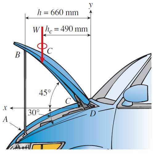
16 16 Sample Problem For the compound roof structure shown, determine the axial stress developed in members AE and EG. q = 20 kn/m, A AE = A EG = 23 cm 2. Solution 1. Reaction force ql 0 Fy FRA FRB kn 2 2. Axial force in EG q 2 0 M C F F EG RA F kn EG
17 17 3. Equilibrium at joint E F EG FAE cos 4.37 FAE F 366 kn AE Axial stresses in members AE and EG EG AE 3 F EG 155 MPa 4 A EG 3 F AE 159 MPa 4 A AE
18 18 Stresses Acting on Oblique Sections A p A cos F F cos cos A A 2 p cos cos p sin sin 2 2 α: defined as the angle measured from cross section normal to oblique cross section normal.
19 19 On cross section: maximum normal stress; zero shearing stress. On 45 oblique cross section: maximum shearing stress max 0 sin(90 ), 0 cos (45 )

20 On 90 oblique cross section: zero normal and shearing stress. 20
21 b Deformation of Axially Loaded Bars Longitudinal (axial) & transverse strains b b L L+L Longitudinal strain: L L Transverse strain: b b Connection between longitudinal and transverse strain ν: Poisson s ratio / 21
22 22 Deformation of Axially Loaded Bars Consider a differential cube of side length a, b and c F bc L Ka Ka bc E K This linear relation is referred to as the one-dimensional Hooke s law, with E denoting the Young s modulus. The measurement of axial deformation LF F L N N L L L E AE EA EA: Tension (Compression) rigidity

23 Elastic Constants of Engineering Materials 23
24 Elastic Constants of Engineering Materials 24
25 Nonuniform Tension/compression Pure tension/compression formula refers to a prismatic bar subjected to axial forces acting only at the ends. Nonuniform tension/compression differs from pure tension in that the bar need not to be prismatic and the applied axial forces may act anywhere along the axis of the bar. Bars in nonuniform tension/compression can be analyzed by applying the formulas of pure tension/compression to finite segments of the bar and then adding the results, or by applying the formulas to differential elements of the bar and then integrating. L L F L Ni i i i i EA i i L L FN x dx L dl 0 0 EA x 25
26 Sample Problem Consider an axially loaded bar with varied cross section. Given: E = 210 GPa; Section 1 (circular): d 1 = 20 mm; Section 2 (square): side length a = 25 mm, 2 = -30 MPa; Section 3 (circular) d 3 =12mm. Find: Total change in bar length L. F F 0.2 m 0.4 m 0.2 m Solution: F 2 2 2A2 30 MPa 25 mm kn FN L 1 1 FN L 2 2 FN L L 0.272mm EA1 EA2 EA π π

27 Sample Problem Determine the elongation of the bar due to the end load P. Solution: x d d d d L x A B A 2 d 2 x x A x d d d 4 4 L A B A L FN dx L 4Pdx L 0 EA 0 x x E d A db d A L x d d A db d A 4PL L L 0 2 E db d A x d A db d A L 4PL 1 B A x E d d d A db d A L 4PL 1 1 4PL E d d d d Ed d B A A B A B Cannot be assumed as a prismatic bar that has the diameter (d A +d B )/2. For the special case of a prismatic bar: L 4PL PL 2 Ed EA L
28 Sample Problem Deformation of a uniform bar due to gravity. Given: cross section area A, density ρ, Young s modulus E. Find: Maximum normal stress and axial length change. Solution: 1. Axial forces and stresses q=ρga; F N (x)= ρgax; ζ(x)= F N (x)/a= ρgx, ζ max = ρgl FN( x)d x FN( x)dx gaxdx gl 2. Deformation: d( L) L EA EA EA 2E l 0 0 l 2 x x L q dx F N (x) F N (x) F N (x) ρgal 28
 and has a cross-sectional area of 500 mm 2. Link CD is made of steel (E = 200 GPa) and has a cross-sectional area of (600 mm 2 ).")
29 Sample Problem SOLUTION: Apply a free-body analysis to the bar BDE to find the forces exerted by links AB and DC. The rigid bar BDE is supported by two links AB and CD. Link AB is made of aluminum (E = 70 GPa) and has a cross-sectional area of 500 mm 2. Link CD is made of steel (E = 200 GPa) and has a cross-sectional area of (600 mm 2 ). For the 30-kN force shown, determine the deflection a) of B, b) of D, and c) of E. Evaluate the deformation of links AB and DC or the displacements of B and D. Work out the geometry to find the deflection at E given the deflections at B and D. 29


30 SOLUTION: Free body: Bar BDE Displacement of B: B PL AE N 0.3m m 7010 Pa m B 0.514mm M kN0.6m F 0.2m F B CD M D 90kN tension kN0.4m F 0.2m F AB 60kN compression CD AB Displacement of D: D PL AE N 0.4m m Pa m D 0.300mm

31 31 Displacement of E: BB DD BH HD 0.514mm mm x 73.7 mm 200mm x x EE DD E 0.300mm E HE HD 1.928mm mm 73.7 mm E 1.928mm
32 Sample Problem Given: tension rigidity of bar 1, 2 and 3 = EA, AB rigid, F and L. Find: the vertical and horizontal displacement at C. x y C C FL 2EA 32
33 33 Sample Problem Determine the vertical and horizontal displacement of A. AB is rigid. A F E B D 0 45 C
34 Hint: A A y A x BB O EE O, AA O EE O B A E E O LED B E F E B L BC B A A F 0 45 BB BO LBC EB EO EB EO EE EO LED EO EO EO EO EB OB BB A A AO Ay AE EO AE EO Ay Ax AO AE EO EE EO LED EO EO D C 34
35 Sample Problem (Poisson s Ratio) A circular tube of inner diameter d = 60 mm and outer diameter D = 80 mm is subjected to an axial load of F = 200 kn, determine the wall thickness under the deformed state. E = 200 GPa, ν = 0.3. F Solution: F EA D d D d 6 E S s mm mm mm Poisson s ratio is the same for all transverse directions. (Isotropy) 6 35
36 36 Sample Problem (Large Deformation) Given: d = 1 mm, ε = , E = 210 GPa. Determine the axial stress in wire, the displacement of C, and the force F. Solution: 9 1. Axial stress in the wire: E MPa 2. The displacement of C AC AC m L L L L L L L L C AC AC AC AC AC AC m 3. The force F (Equilibrium must be analyzed under the deformed state.) 2 C sin N F FN BAC A LAC
37 37 Sample Problem (Pressure Vessel) For the thin-walled pressure vessel shown, D, δ, and p denote the vessel inner diameter, wall thickness and pressure respectively. Determine: the axial stress, circumferential stress, and the elongation of vessel circumference, diameter and length. δ l p D
38 F axial a a 0 2 πd p πd 4 pd 4 a Dδ a D δ p D 2 4 F circumferential 0 a D 2 c b sin pb d 0 2 2bc pbd pd c 2 b: an arbitrarily chosen axial length c p c 38
39 39 Circumferential stress: Axial stress: a c pd 4 pd 2 Radial stress: D p pd 2 pd 4
40 Elongation of the vessel circumference FL N t A D c EA EA Elongation of the vessel diameter 2 2 t pd pd D 1 2E D 2E Elongation of the vessel length FL N a A l a EA pdl EA 4E 2 2 pd D pd pd 1 2 E 2E D 2E Transverse strain t pd D pd c D L 2E L 2E t D 40
41 Strain Energy Strain energy is developed in solid materials due to elastic deformation induced by external loading. L L 1 F Strain energy and work in pure tension/compression L FL EA N U W FN L L 2 2EA 2L F FL N EA The one-half is due to the assumption that external loading is applied gradually, starting from zero. O L 41
42 42 Strain Energy Nonuniform tension/compression U U 2 FN ili 2EA i i i i i U 2 L L FN ( x) dx du 2 EA( x) 0 0
43 Strain Energy Density (Energy per Unit Volume) Consider a differential cube of side length a, b and c 1 1 U FL bc a 2 2 U 1 u V 2 Total strain energy calculated from density FN FN FN dx U udv dv A dx A dx V V 2 L 2 L 2 A EA L 2EA For constant E, F N, and A U FL 2 N 2EA 43
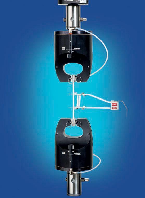
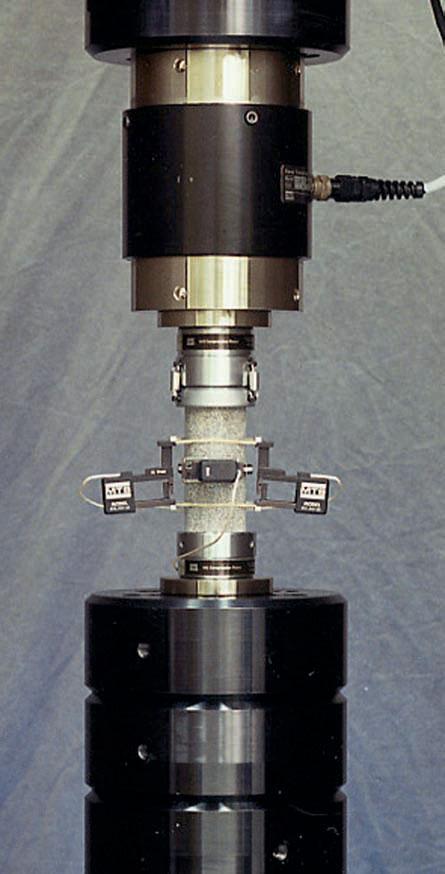
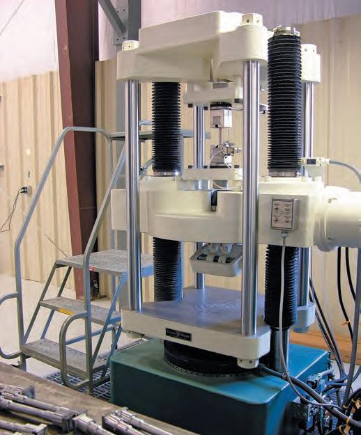
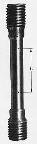
44 Mechanical Behavior of Materials Mechanical behavior of materials focus on the strength and deformation characteristics of solid materials under external loading. Tensile specimen For circular tensile specimen For square tensile specimen L = 10d, 5d = 11.3 A, 5.65 A L = 11.3b, 5.65b. Compressive specimen: L = 13d, 13b d b L L 44
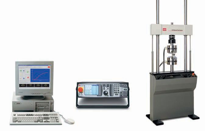
45 Mechanical Behavior of Materials 45
46 Nominal Stress-strain Curve Find more animations at 46
 / L initial 100% Percent reduction in area ψ = (A initial - A final ) / A initial 100%")
47 Stress and Deformation Indices of Low-carbon Steel ζ d b c a ζ b ζ e ζ ζ p s O p : Proportional limit e : Elastic limit Y : Yield stress u : Ultimate stress Stress-strain Diagram Percent elongation: δ = (L final - L initial ) / L initial 100% Percent reduction in area ψ = (A initial - A final ) / A initial 100% ε

48 Yield Stress, Ultimate Stress and Percent Elongation

49 Yield Stress, Ultimate Stress and Percent Elongation 49
50 Yield Stress, Ultimate Stress and Percent Elongation 50
51 Exercise Based on the three stress-strain curves shown in the figure, which one of the following regarding ultimate stress, Young s modulus and percent elongation is correct? ζ A: u 1 u 2 u 3 E 1 E 2 E B: u 2 u 1 u E E E O C: D: u 3 u 1 u u 1 u 2 u E E E E E E ε 51
52 Strain (Work) Hardening Unloading at point B during hardening stage down to zero force. EB almost parallel to OA. (Unloading law) Deformation in the hardening stage is composed of elastic ( L e ) and plastic elongation ( L p ). If the test sample is reloaded at point E, the linear elastic (proportional) limit substantially increases. As a result, the overall deformation the sample can endure decreases. In engineering practice, strain hardening is often employed to increase the maximum resistance force within linear elastic scope. F O ζ O A L p E L e F B L Force-displacement Diagram A E B F p e Stress-strain Diagram ε 52
53 Sample Problem Given: E = 200 GPa, unloading at ζ = 310 MPa during hardening stage, total strain ε e + ε p = Find: ε e and ε p
54 Solution: e E p e e Remark: in experimental reports, strain often takes the unit of micro-strain, i.e (ε)=20000 (με)
55 55 Sample Problem Low-carbon steel loading and unloading experiments. Given: E = 210 GPa, ζ P = 210 MPa. Find: 1. normal stress at the strain level ε = (under linear elastic limit); 2. normal stress at a point in hardening stage, unloading from which results in ε = 0.08 and ε p = Solution: 1. Under linear elastic limit E Pa 210MPa p 2. During hardening stage: E e ( ) Pa 420 MPa
56 56 Mechanical Behavior of General Ductile Materials under Tension Possess distinctive ζ Y and ζ u ζ May not have yielding and/or 1500 ζ CrMnSi steel localized deformation stage Relatively large extension rate after fracture (δ 5%) O 0.2% 45 # steel Q235 steel Al alloy brass ε If there is no obvious yielding stage: take the normal stress corresponding to 0.2% plastic strain as yield limit (ζ p0.2 )
57 Mechanical Behavior of Brittle Materials under Tension ζ-ε is a slightly curved line and approximately obeys the Hooke s law No yielding, hardening and localized deformation stage u tangent The ultimate stress is the only index Relatively small percent elongation after fracture (δ = 2%-5%) Tangential modulus: slope at any point of ζ-ε curve intersection secant modulus: can be defined at ε = 0.1% O 0.1% 57
 initial cross-sectional area used in normal stress calculation.")
58 Mechanical Behavior of Low-carbon Steel under Compression ζ compressive tensile ζ Y ζ p O ε E, ζ p, ζ Y take the same values as in tensile tests. Cannot obtain compressive ultimate stress due to the (constant) initial cross-sectional area used in normal stress calculation. Compressive mechanical behavior of low-carbon steel is obtained from its tensile indices. 58
59 Mechanical Behavior of Cast Iron under Compression ζ ζ c u Compressive O Tensile There is only very short linear ζ-ε curve (only approximately follows Hooke s law). Missing yielding stage (no obvious ζ Y ). Much larger compressive ultimate stress (typically 4-5 times that of tensile strength limit). Final damage is in the form of shearing along a surface 45 0 from axis. ζ t u ε 59
60 Mechanical Behavior of Concrete Compressive ultimate stress is much larger than its tensile counterpart (5-20 times) Compressive behavior depends on the frictional state at sample ends Under frictional end-condition, sample is composed of two trapezoidal cones under mirror-symmetry upon damage ζ-ε comprises a short straight line, followed by an obvious curve. Elastic modulus can be defined by the slope of secant line at ζ = 0.4ζ u Small compressive ratio after fracture. u u Frictional ends Lubricated ends 60
61 Mechanical Behavior of Wood Material behavior is transversely isotropic. Longitudinal tensile strength is unstable due to knots. Longitudinal compressive strength is insensitive to knots. Much larger longitudinal compressive strength than the transverse one. Most often used as compressive or support bars in engineering Transverse compression Longitudinal Compression Longitudinal tension Longitudinal compression Transverse compression 61
62 Mechanical Behavior of Composite Materials Mechanical properties of composite materials is mostly determined by the way how fibers are arranged (anisotropic). Influence from temperature, stress concentration (geometric factors), and strain rate (viscoelasticity) High ultimate stress and low plasticity under low temperature. Low ultimate stress and low plasticity under high stress concentration state Low ultimate stress and high plasticity under high strain rate 62
63 63 Mechanical Behavior of Viscoelastic Materials ζ = ε f(t) - linear visco-elasticity ζ = f(ε, t) - non-linear visco-elasticity Creep: increasing strain with time under constant stress Relaxation: decreasing stress with time under constant strain
64 64 Strength Condition Limit stress ( lim ): the stress under which mechanical components get damaged. Damage Criteria: yielding (ζ Y ) for ductile materials; fracture (ζ u ) for brittle materials Allowable Stress []: the maximum stress allowed in engineering practice. It is typically taken as one n th (Safety Factor) of the limit stress Strength Condition: Strength Analysis: (1) Strength check: (2) Cross-section design: (3) Find allowable load: max max n lim A F [ ] N max FN max A [ ]
65 65 Sample Problem Given: d = 14 mm, [ζ] = 170 MPa, uniaxial tension load F = 2.5 kn. Check the strength condition of the circular bar. Solution max F π N, max 2 6 A Pa 162 MPa<[ ] The strength condition is satisfied.
66 Sample Problem Given: A AC = 450 mm 2, A BC = 250 mm 2, E AC = E BC, [ζ] = 100 MPa. Find: the maximum allowable load F of the truss. Solution: 1. Find F NAC and F NBC Method of joint at C: F x = 0, F NBC sin F NAC sin30 0 = 0 F y = 0, F NBC cos F NAC cos F = 0 A F NAC C F F NBC B We get: F NAC = 0.732F, F NBC = 0.517F 66
67 67 2. Allowable axial force in bar AC and BC so: [F] kn So: [F] kn m FN AC 0.732F A m FN BC 0.517F A Pa Pa 3. Allowable load [F] Take the smaller value: [F] kn.
68 Sample Problem Given: F = 75 kn, [ζ] = 160 MPa. Find: the minimum A AB and A BC. Solution: A 1. Find F NAB and F NBC By the Method of joint at B: F y = 0, F NBC cos F = 0 F x = 0, F NBC cos F NAC = 0 45 We get: F NAC = F,F NBC = F F B Minimum cross-sectional area A A AB BC F 7510 [ ] F [ ] NAB m cm 6 3 NBC m cm 6 C 68

69 69 Failure of Brittle vs. Ductile Bars under Tension Brittle Ductile Under uniaxial tension, brittle bars break along crosssections while ductile ones glide along 45 0 sections during yielding?


70 70 Stress Concentration Stress concentration: rapid stress increase at specific locations where geometric defects and/or abrupt cross-sectional area change occurs
71 Stress-concentration factor for flat bars with circular holes 71
72 Stress-concentration factor for flat bars with shoulder fillets. The dashed line is for a full quarter-circular fillet. 72
73 Stress-concentration factor for round bars with shoulder fillets. The dashed line is for a full quarter-circular fillet. 73

74 74 Sample Problem SOLUTION: Determine the geometric ratios and the stress concentration factor. Determine the largest axial load P that can be safely supported by a flat steel bar consisting of two portions, both 10 mm thick, and respectively c = 40 and b = 60 mm wide, connected by fillets of radius R = 8 mm. Assume an allowable normal stress of 165 MPa. Find the allowable average normal stress using the material allowable normal stress and the stress concentration factor. Apply the definition of normal stress to find the allowable load.
75 75 Determine the geometric ratios and the stress concentration factor. b 60 mm R 8mm K 1.82 c 40mm c 40mm
76 76 Determine the geometric ratios and the stress concentration factor. b c 60 mm R 8mm mm c 40mm Find the allowable average normal stress using the material allowable normal stress and the stress concentration factor. ave K max 165MPa MPa 1.82 Apply the definition of normal stress to find the allowable load. 3 P A ave 40 mm 10 mm 90.7 MPa N K
77 Contents Introduction( 拉压变形简介 ) Diagram of Axial Forces( 轴力图 ) Concept of Stresses( 应力的概念 ) General Stress State of a Point( 点的一般应力状态 ) Stresses Acting on Cross Sections( 拉压杆横截面上的应力 ) Saint-Venant s Principle( 圣维南原理 ) Stresses Acting on Oblique Sections( 拉压杆斜截面上的应力 ) Deformation of Axially Loaded Bars( 拉压杆的变形 ) Elastic Constants of Engineering Materials( 常见工程材料的弹性常数 ) Nonuniform Tension/compression( 非均匀拉压 ) Strain Energy( 应变能 ) Strain Energy Density( 应变能密度 ) Mechanical Behavior of Materials( 材料的力学性能 ) Nominal Stress-strain Curve( 名义应力应变曲线 ) Stress and Deformation Indices of Low-carbon Steel( 低碳钢的应力和变形指标 ) 77
78 Contents Yield Stress, Ultimate Stress and Percent Elongation of Engineering Materials ( 常见工程材料的屈服应力 强度极限和断后伸长率 ) Strain (Work) Hardening( 冷作硬化 ) Mechanical Behavior of General Ductile Materials under Tension( 塑性材料的拉伸力学性能 ) Mechanical Behavior of Brittle Materials under Tension( 脆性材料的拉伸 ) Mechanical Behavior of Low-carbon Steel under Compression( 低碳钢的压缩 ) Mechanical Behavior of Cast Iron under Compression( 铸铁的压缩力学性能 ) Mechanical Behavior of Creet( 混凝土的力学性能 ) Mechanical Behavior of Wood( 木材的力学性能 ) Mechanical Behavior of Composite Materials( 复合材料的力学性能 ) Mechanical Behavior of Viscoelastic Materials( 粘弹性材料的力学性能 ) Strength Condition( 强度条件 ) Failure of Brittle vs. Ductile Bars under Tension( 脆性和塑性杆件的拉伸失效 ) Stress Concentration( 拉压杆中的应力集中现象 ) 78
MECHANICS OF MATERIALS
 CHAPTER 2 MECHANICS OF MATERIALS Ferdinand P. Beer E. Russell Johnston, Jr. John T. DeWolf David F. Mazurek Lecture Notes: J. Walt Oler Texas Tech University Stress and Strain Axial Loading 2.1 An Introduction
Torsion.
 Torsion mi@seu.edu.cn Contents Introduction to Torsion( 扭转简介 ) Examples of Torsion Shafts( 扭转轴示例 ) Sign Convention of Torque( 扭矩符号规则 ) Torque Diagram( 扭矩图 ) Power & Torque( 功率与扭矩 ) Internal Torque & Stress
NORMAL STRESS. The simplest form of stress is normal stress/direct stress, which is the stress perpendicular to the surface on which it acts.
 NORMAL STRESS The simplest form of stress is normal stress/direct stress, which is the stress perpendicular to the surface on which it acts. σ = force/area = P/A where σ = the normal stress P = the centric
Mechanical Properties of Materials
 Mechanical Properties of Materials Strains Material Model Stresses Learning objectives Understand the qualitative and quantitative description of mechanical properties of materials. Learn the logic of
Samantha Ramirez, MSE. Stress. The intensity of the internal force acting on a specific plane (area) passing through a point. F 2
 passing through a point. F 2") Samantha Ramirez, MSE Stress The intensity of the internal force acting on a specific plane (area) passing through a point. Δ ΔA Δ z Δ 1 2 ΔA Δ x Δ y ΔA is an infinitesimal size area with a uniform force
Samantha Ramirez, MSE Stress The intensity of the internal force acting on a specific plane (area) passing through a point. Δ ΔA Δ z Δ 1 2 ΔA Δ x Δ y ΔA is an infinitesimal size area with a uniform force
ME 2570 MECHANICS OF MATERIALS
 ME 2570 MECHANICS OF MATERIALS Chapter III. Mechanical Properties of Materials 1 Tension and Compression Test The strength of a material depends on its ability to sustain a load without undue deformation
EMA 3702 Mechanics & Materials Science (Mechanics of Materials) Chapter 2 Stress & Strain - Axial Loading
 Chapter 2 Stress & Strain - Axial Loading") MA 3702 Mechanics & Materials Science (Mechanics of Materials) Chapter 2 Stress & Strain - Axial Loading MA 3702 Mechanics & Materials Science Zhe Cheng (2018) 2 Stress & Strain - Axial Loading Statics
MA 3702 Mechanics & Materials Science (Mechanics of Materials) Chapter 2 Stress & Strain - Axial Loading MA 3702 Mechanics & Materials Science Zhe Cheng (2018) 2 Stress & Strain - Axial Loading Statics
MECHANICS OF MATERIALS
 Third E CHAPTER 2 Stress MECHANICS OF MATERIALS Ferdinand P. Beer E. Russell Johnston, Jr. John T. DeWolf Lecture Notes: J. Walt Oler Texas Tech University and Strain Axial Loading Contents Stress & Strain:
Chapter 4-b Axially Loaded Members
 CIVL 222 STRENGTH OF MATERIALS Chapter 4-b Axially Loaded Members AXIAL LOADED MEMBERS Today s Objectives: Students will be able to: a) Determine the elastic deformation of axially loaded member b) Apply
Solid Mechanics Chapter 1: Tension, Compression and Shear
 Solid Mechanics Chapter 1: Tension, Compression and Shear Dr. Imran Latif Department of Civil and Environmental Engineering College of Engineering University of Nizwa (UoN) 1 Why do we study Mechanics
Stress State.
 Stress State mi@seu.edu.cn Contents The Stress State of a Point( 点的应力状态 ) Simple, General & Principal Stress State( 简单 一般和主应力状态 ) Ordering of Principal Stresses( 主应力排序 ) On the Damage Mechanisms of Materials(
Mechanics of Materials II. Chapter III. A review of the fundamental formulation of stress, strain, and deflection
 Mechanics of Materials II Chapter III A review of the fundamental formulation of stress, strain, and deflection Outline Introduction Assumtions and limitations Axial loading Torsion of circular shafts
MECHANICS OF MATERIALS
 CHATR Stress MCHANICS OF MATRIALS and Strain Axial Loading Stress & Strain: Axial Loading Suitability of a structure or machine may depend on the deformations in the structure as well as the stresses induced
4.MECHANICAL PROPERTIES OF MATERIALS
 4.MECHANICAL PROPERTIES OF MATERIALS The diagram representing the relation between stress and strain in a given material is an important characteristic of the material. To obtain the stress-strain diagram
MECE 3321 MECHANICS OF SOLIDS CHAPTER 3
 MECE 3321 MECHANICS OF SOLIDS CHAPTER 3 Samantha Ramirez TENSION AND COMPRESSION TESTS Tension and compression tests are used primarily to determine the relationship between σ avg and ε avg in any material.
[5] Stress and Strain
![[5] Stress and Strain](/thumbs/95/123344550.jpg "[5] Stress and Strain") [5] Stress and Strain Page 1 of 34 [5] Stress and Strain [5.1] Internal Stress of Solids [5.2] Design of Simple Connections (will not be covered in class) [5.3] Deformation and Strain [5.4] Hooke s Law
[5] Stress and Strain Page 1 of 34 [5] Stress and Strain [5.1] Internal Stress of Solids [5.2] Design of Simple Connections (will not be covered in class) [5.3] Deformation and Strain [5.4] Hooke s Law
STATICALLY INDETERMINATE STRUCTURES
 STATICALLY INDETERMINATE STRUCTURES INTRODUCTION Generally the trusses are supported on (i) a hinged support and (ii) a roller support. The reaction components of a hinged support are two (in horizontal
MECHANICS OF MATERIALS
 Third CHTR Stress MCHNICS OF MTRIS Ferdinand. Beer. Russell Johnston, Jr. John T. DeWolf ecture Notes: J. Walt Oler Texas Tech University and Strain xial oading Contents Stress & Strain: xial oading Normal
Theory at a Glance (for IES, GATE, PSU)
") 1. Stress and Strain Theory at a Glance (for IES, GATE, PSU) 1.1 Stress () When a material is subjected to an external force, a resisting force is set up within the component. The internal resistance force
1. Stress and Strain Theory at a Glance (for IES, GATE, PSU) 1.1 Stress () When a material is subjected to an external force, a resisting force is set up within the component. The internal resistance force
Introduction to Engineering Materials ENGR2000. Dr. Coates
 Introduction to Engineering Materials ENGR2 Chapter 6: Mechanical Properties of Metals Dr. Coates 6.2 Concepts of Stress and Strain tension compression shear torsion Tension Tests The specimen is deformed
Mechanics of Materials Primer
 Mechanics of Materials rimer Notation: A = area (net = with holes, bearing = in contact, etc...) b = total width of material at a horizontal section d = diameter of a hole D = symbol for diameter E = modulus
UNIT I SIMPLE STRESSES AND STRAINS
 Subject with Code : SM-1(15A01303) Year & Sem: II-B.Tech & I-Sem SIDDHARTH GROUP OF INSTITUTIONS :: PUTTUR Siddharth Nagar, Narayanavanam Road 517583 QUESTION BANK (DESCRIPTIVE) UNIT I SIMPLE STRESSES
STRESS, STRAIN AND DEFORMATION OF SOLIDS
 VELAMMAL COLLEGE OF ENGINEERING AND TECHNOLOGY, MADURAI 625009 DEPARTMENT OF CIVIL ENGINEERING CE8301 STRENGTH OF MATERIALS I -------------------------------------------------------------------------------------------------------------------------------
five Mechanics of Materials 1 ARCHITECTURAL STRUCTURES: FORM, BEHAVIOR, AND DESIGN DR. ANNE NICHOLS SUMMER 2017 lecture
 ARCHITECTURAL STRUCTURES: FORM, BEHAVIOR, AND DESIGN DR. ANNE NICHOLS SUMMER 2017 lecture five mechanics www.carttalk.com of materials Mechanics of Materials 1 Mechanics of Materials MECHANICS MATERIALS
Strength of Materials (15CV 32)
") Strength of Materials (15CV 32) Module 1 : Simple Stresses and Strains Dr. H. Ananthan, Professor, VVIET,MYSURU 8/21/2017 Introduction, Definition and concept and of stress and strain. Hooke s law, Stress-Strain
Strength of Materials (15CV 32) Module 1 : Simple Stresses and Strains Dr. H. Ananthan, Professor, VVIET,MYSURU 8/21/2017 Introduction, Definition and concept and of stress and strain. Hooke s law, Stress-Strain
UNIT 1 STRESS STRAIN AND DEFORMATION OF SOLIDS, STATES OF STRESS 1. Define stress. When an external force acts on a body, it undergoes deformation.
 UNIT 1 STRESS STRAIN AND DEFORMATION OF SOLIDS, STATES OF STRESS 1. Define stress. When an external force acts on a body, it undergoes deformation. At the same time the body resists deformation. The magnitude
The University of Melbourne Engineering Mechanics
 The University of Melbourne 436-291 Engineering Mechanics Tutorial Four Poisson s Ratio and Axial Loading Part A (Introductory) 1. (Problem 9-22 from Hibbeler - Statics and Mechanics of Materials) A short
Constitutive Equations (Linear Elasticity)
") Constitutive quations (Linear lasticity) quations that characterize the physical properties of the material of a system are called constitutive equations. It is possible to find the applied stresses knowing
Constitutive quations (Linear lasticity) quations that characterize the physical properties of the material of a system are called constitutive equations. It is possible to find the applied stresses knowing
Unit I Stress and Strain
 Unit I Stress and Strain Stress and strain at a point Tension, Compression, Shear Stress Hooke s Law Relationship among elastic constants Stress Strain Diagram for Mild Steel, TOR steel, Concrete Ultimate
ME 243. Mechanics of Solids
 ME 243 Mechanics of Solids Lecture 2: Stress and Strain Ahmad Shahedi Shakil Lecturer, Dept. of Mechanical Engg, BUET E-mail: sshakil@me.buet.ac.bd, shakil6791@gmail.com Website: teacher.buet.ac.bd/sshakil
Bending Deflection.
 ending Deflection mi@seu.edu.cn ontents The Elastic urve, Deflection & Slope ( 挠曲线 挠度和转角 ) Differential Euation of the Elastic urve( 挠曲线微分方程 ) Deflection & Slope by Integration( 积分法求挠度和转角 ) oundary onditions(
Free Body Diagram: Solution: The maximum load which can be safely supported by EACH of the support members is: ANS: A =0.217 in 2
 Problem 10.9 The angle β of the system in Problem 10.8 is 60. The bars are made of a material that will safely support a tensile normal stress of 8 ksi. Based on this criterion, if you want to design the
Russell C. Hibbeler. Chapter 1: Stress
 Russell C. Hibbeler Chapter 1: Stress Introduction Mechanics of materials is a study of the relationship between the external loads on a body and the intensity of the internal loads within the body. This
PERIYAR CENTENARY POLYTECHNIC COLLEGE PERIYAR NAGAR - VALLAM THANJAVUR. DEPARTMENT OF MECHANICAL ENGINEERING QUESTION BANK
 PERIYAR CENTENARY POLYTECHNIC COLLEGE PERIYAR NAGAR - VALLAM - 613 403 - THANJAVUR. DEPARTMENT OF MECHANICAL ENGINEERING QUESTION BANK Sub : Strength of Materials Year / Sem: II / III Sub Code : MEB 310
Sub. Code:
 Important Instructions to examiners: ) The answers should be examined by key words and not as word-to-word as given in the model answer scheme. ) The model answer and the answer written by candidate may
Structural Analysis I Chapter 4 - Torsion TORSION
 ORSION orsional stress results from the action of torsional or twisting moments acting about the longitudinal axis of a shaft. he effect of the application of a torsional moment, combined with appropriate
QUESTION BANK SEMESTER: III SUBJECT NAME: MECHANICS OF SOLIDS
 QUESTION BANK SEMESTER: III SUBJECT NAME: MECHANICS OF SOLIDS UNIT 1- STRESS AND STRAIN PART A (2 Marks) 1. Define longitudinal strain and lateral strain. 2. State Hooke s law. 3. Define modular ratio,
Stress-Strain Behavior
 Stress-Strain Behavior 6.3 A specimen of aluminum having a rectangular cross section 10 mm 1.7 mm (0.4 in. 0.5 in.) is pulled in tension with 35,500 N (8000 lb f ) force, producing only elastic deformation.
The science of elasticity
 The science of elasticity In 1676 Hooke realized that 1.Every kind of solid changes shape when a mechanical force acts on it. 2.It is this change of shape which enables the solid to supply the reaction
Symmetric Bending of Beams
 Symmetric Bending of Beams beam is any long structural member on which loads act perpendicular to the longitudinal axis. Learning objectives Understand the theory, its limitations and its applications
INTRODUCTION TO STRAIN
 SIMPLE STRAIN INTRODUCTION TO STRAIN In general terms, Strain is a geometric quantity that measures the deformation of a body. There are two types of strain: normal strain: characterizes dimensional changes,
Mechanics in Energy Resources Engineering - Chapter 5 Stresses in Beams (Basic topics)
") Week 7, 14 March Mechanics in Energy Resources Engineering - Chapter 5 Stresses in Beams (Basic topics) Ki-Bok Min, PhD Assistant Professor Energy Resources Engineering i Seoul National University Shear
Week 7, 14 March Mechanics in Energy Resources Engineering - Chapter 5 Stresses in Beams (Basic topics) Ki-Bok Min, PhD Assistant Professor Energy Resources Engineering i Seoul National University Shear
Chapter 3. Load and Stress Analysis
 Chapter 3 Load and Stress Analysis 2 Shear Force and Bending Moments in Beams Internal shear force V & bending moment M must ensure equilibrium Fig. 3 2 Sign Conventions for Bending and Shear Fig. 3 3
CHAPTER 6 MECHANICAL PROPERTIES OF METALS PROBLEM SOLUTIONS
 CHAPTER 6 MECHANICAL PROPERTIES OF METALS PROBLEM SOLUTIONS Concepts of Stress and Strain 6.1 Using mechanics of materials principles (i.e., equations of mechanical equilibrium applied to a free-body diagram),
Chapter 8 Structural Design and Analysis. Strength and stiffness 5 types of load: Tension Compression Shear Bending Torsion
 Chapter 8 Structural Design and Analysis 1 Strength and stiffness 5 types of load: Tension Compression Shear Bending Torsion Normal Stress Stress is a state when a material is loaded. For normal forces
STRESS STRAIN AND DEFORMATION OF SOLIDS, STATES OF STRESS
 1 UNIT I STRESS STRAIN AND DEFORMATION OF SOLIDS, STATES OF STRESS 1. Define: Stress When an external force acts on a body, it undergoes deformation. At the same time the body resists deformation. The
QUESTION BANK DEPARTMENT: CIVIL SEMESTER: III SUBJECT CODE: CE2201 SUBJECT NAME: MECHANICS OF SOLIDS UNIT 1- STRESS AND STRAIN PART A
 DEPARTMENT: CIVIL SUBJECT CODE: CE2201 QUESTION BANK SEMESTER: III SUBJECT NAME: MECHANICS OF SOLIDS UNIT 1- STRESS AND STRAIN PART A (2 Marks) 1. Define longitudinal strain and lateral strain. 2. State
MECH 401 Mechanical Design Applications
 MECH 401 Mechanical Design Applications Dr. M. O Malley Master Notes Spring 008 Dr. D. M. McStravick Rice University Updates HW 1 due Thursday (1-17-08) Last time Introduction Units Reliability engineering
Chapter 5 CENTRIC TENSION OR COMPRESSION ( AXIAL LOADING )
") Chapter 5 CENTRIC TENSION OR COMPRESSION ( AXIAL LOADING ) 5.1 DEFINITION A construction member is subjected to centric (axial) tension or compression if in any cross section the single distinct stress
Chapter 5 CENTRIC TENSION OR COMPRESSION ( AXIAL LOADING ) 5.1 DEFINITION A construction member is subjected to centric (axial) tension or compression if in any cross section the single distinct stress
KINGS COLLEGE OF ENGINEERING DEPARTMENT OF MECHANICAL ENGINEERING QUESTION BANK. Subject code/name: ME2254/STRENGTH OF MATERIALS Year/Sem:II / IV
 KINGS COLLEGE OF ENGINEERING DEPARTMENT OF MECHANICAL ENGINEERING QUESTION BANK Subject code/name: ME2254/STRENGTH OF MATERIALS Year/Sem:II / IV UNIT I STRESS, STRAIN DEFORMATION OF SOLIDS PART A (2 MARKS)
Bending Internal Forces.
 ending Internal orces mi@seu.edu.cn Contents Introduction( 弯曲变形简介 ) The orms of Internal orces in eams( 梁中内力的形式 ) Symmetric ending( 对称弯曲 ) Types of eams( 静定梁的分类 ) Types of Supports and Reactions( 梁的支撑种类及相应的支座反力形式
Chapter 7. Highlights:
 Chapter 7 Highlights: 1. Understand the basic concepts of engineering stress and strain, yield strength, tensile strength, Young's(elastic) modulus, ductility, toughness, resilience, true stress and true
STANDARD SAMPLE. Reduced section " Diameter. Diameter. 2" Gauge length. Radius
 MATERIAL PROPERTIES TENSILE MEASUREMENT F l l 0 A 0 F STANDARD SAMPLE Reduced section 2 " 1 4 0.505" Diameter 3 4 " Diameter 2" Gauge length 3 8 " Radius TYPICAL APPARATUS Load cell Extensometer Specimen
Mechanical properties 1 Elastic behaviour of materials
 MME131: Lecture 13 Mechanical properties 1 Elastic behaviour of materials A. K. M. B. Rashid Professor, Department of MME BUET, Dhaka Today s Topics Deformation of material under the action of a mechanical
PDDC 1 st Semester Civil Engineering Department Assignments of Mechanics of Solids [ ] Introduction, Fundamentals of Statics
![PDDC 1 st Semester Civil Engineering Department Assignments of Mechanics of Solids [ ] Introduction, Fundamentals of Statics](/thumbs/92/109382806.jpg "PDDC 1 st Semester Civil Engineering Department Assignments of Mechanics of Solids [ ] Introduction, Fundamentals of Statics") Page1 PDDC 1 st Semester Civil Engineering Department Assignments of Mechanics of Solids [2910601] Introduction, Fundamentals of Statics 1. Differentiate between Scalar and Vector quantity. Write S.I.
Page1 PDDC 1 st Semester Civil Engineering Department Assignments of Mechanics of Solids [2910601] Introduction, Fundamentals of Statics 1. Differentiate between Scalar and Vector quantity. Write S.I.
Downloaded from Downloaded from / 1
 PURWANCHAL UNIVERSITY III SEMESTER FINAL EXAMINATION-2002 LEVEL : B. E. (Civil) SUBJECT: BEG256CI, Strength of Material Full Marks: 80 TIME: 03:00 hrs Pass marks: 32 Candidates are required to give their
Elasticity and Plasticity. 1.Basic principles of Elasticity and plasticity. 2.Stress and Deformation of Bars in Axial load 1 / 59
 Elasticity and Plasticity 1.Basic principles of Elasticity and plasticity 2.Stress and Deformation of Bars in Axial load 1 / 59 Basic principles of Elasticity and plasticity Elasticity and plasticity in
N = Shear stress / Shear strain
 UNIT - I 1. What is meant by factor of safety? [A/M-15] It is the ratio between ultimate stress to the working stress. Factor of safety = Ultimate stress Permissible stress 2. Define Resilience. [A/M-15]
ME Final Exam. PROBLEM NO. 4 Part A (2 points max.) M (x) y. z (neutral axis) beam cross-sec+on. 20 kip ft. 0.2 ft. 10 ft. 0.1 ft.
 M (x) y. z (neutral axis) beam cross-sec+on. 20 kip ft. 0.2 ft. 10 ft. 0.1 ft.") ME 323 - Final Exam Name December 15, 2015 Instructor (circle) PROEM NO. 4 Part A (2 points max.) Krousgrill 11:30AM-12:20PM Ghosh 2:30-3:20PM Gonzalez 12:30-1:20PM Zhao 4:30-5:20PM M (x) y 20 kip ft 0.2
ME 323 - Final Exam Name December 15, 2015 Instructor (circle) PROEM NO. 4 Part A (2 points max.) Krousgrill 11:30AM-12:20PM Ghosh 2:30-3:20PM Gonzalez 12:30-1:20PM Zhao 4:30-5:20PM M (x) y 20 kip ft 0.2
Principal Stresses, Yielding Criteria, wall structures
 Principal Stresses, Yielding Criteria, St i thi Stresses in thin wall structures Introduction The most general state of stress at a point may be represented by 6 components, x, y, z τ xy, τ yz, τ zx normal
Course: US01CPHY01 UNIT 1 ELASTICITY I Introduction:
 Course: US0CPHY0 UNIT ELASTICITY I Introduction: If the distance between any two points in a body remains invariable, the body is said to be a rigid body. In practice it is not possible to have a perfectly
Homework No. 1 MAE/CE 459/559 John A. Gilbert, Ph.D. Fall 2004
 Homework No. 1 MAE/CE 459/559 John A. Gilbert, Ph.D. 1. A beam is loaded as shown. The dimensions of the cross section appear in the insert. the figure. Draw a complete free body diagram showing an equivalent
9 MECHANICAL PROPERTIES OF SOLIDS
 9 MECHANICAL PROPERTIES OF SOLIDS Deforming force Deforming force is the force which changes the shape or size of a body. Restoring force Restoring force is the internal force developed inside the body
UNIVERSITY OF SASKATCHEWAN ME MECHANICS OF MATERIALS I FINAL EXAM DECEMBER 13, 2008 Professor A. Dolovich
 UNIVERSITY OF SASKATCHEWAN ME 313.3 MECHANICS OF MATERIALS I FINAL EXAM DECEMBER 13, 2008 Professor A. Dolovich A CLOSED BOOK EXAMINATION TIME: 3 HOURS For Marker s Use Only LAST NAME (printed): FIRST
MATERIALS FOR CIVIL AND CONSTRUCTION ENGINEERS
 MATERIALS FOR CIVIL AND CONSTRUCTION ENGINEERS 3 rd Edition Michael S. Mamlouk Arizona State University John P. Zaniewski West Virginia University Solution Manual FOREWORD This solution manual includes
CHAPTER 3 THE EFFECTS OF FORCES ON MATERIALS
 CHAPTER THE EFFECTS OF FORCES ON MATERIALS EXERCISE 1, Page 50 1. A rectangular bar having a cross-sectional area of 80 mm has a tensile force of 0 kn applied to it. Determine the stress in the bar. Stress
3D Elasticity Theory
 3D lasticity Theory Many structural analysis problems are analysed using the theory of elasticity in which Hooke s law is used to enforce proportionality between stress and strain at any deformation level.
Name :. Roll No. :... Invigilator s Signature :.. CS/B.TECH (CE-NEW)/SEM-3/CE-301/ SOLID MECHANICS
/SEM-3/CE-301/ SOLID MECHANICS") Name :. Roll No. :..... Invigilator s Signature :.. 2011 SOLID MECHANICS Time Allotted : 3 Hours Full Marks : 70 The figures in the margin indicate full marks. Candidates are required to give their answers
Name :. Roll No. :..... Invigilator s Signature :.. 2011 SOLID MECHANICS Time Allotted : 3 Hours Full Marks : 70 The figures in the margin indicate full marks. Candidates are required to give their answers
Example 3.7 Consider the undeformed configuration of a solid as shown in Figure 3.60.
 162 3. The linear 3-D elasticity mathematical model The 3-D elasticity model is of great importance, since it is our highest order hierarchical model assuming linear elastic behavior. Therefore, it provides
Lecture 8. Stress Strain in Multi-dimension
 Lecture 8. Stress Strain in Multi-dimension Module. General Field Equations General Field Equations [] Equilibrium Equations in Elastic bodies xx x y z yx zx f x 0, etc [2] Kinematics xx u x x,etc. [3]
(48) CHAPTER 3: TORSION
 CHAPTER 3: TORSION") (48) CHAPTER 3: TORSION Introduction: In this chapter structural members and machine parts that are in torsion will be considered. More specifically, you will analyze the stresses and strains in members
(48) CHAPTER 3: TORSION Introduction: In this chapter structural members and machine parts that are in torsion will be considered. More specifically, you will analyze the stresses and strains in members
Aluminum shell. Brass core. 40 in
 PROBLEM #1 (22 points) A solid brass core is connected to a hollow rod made of aluminum. Both are attached at each end to a rigid plate as shown in Fig. 1. The moduli of aluminum and brass are EA=11,000
R13. II B. Tech I Semester Regular Examinations, Jan MECHANICS OF SOLIDS (Com. to ME, AME, AE, MTE) PART-A
 PART-A") SET - 1 II B. Tech I Semester Regular Examinations, Jan - 2015 MECHANICS OF SOLIDS (Com. to ME, AME, AE, MTE) Time: 3 hours Max. Marks: 70 Note: 1. Question Paper consists of two parts (Part-A and Part-B)
SET - 1 II B. Tech I Semester Regular Examinations, Jan - 2015 MECHANICS OF SOLIDS (Com. to ME, AME, AE, MTE) Time: 3 hours Max. Marks: 70 Note: 1. Question Paper consists of two parts (Part-A and Part-B)
VYSOKÁ ŠKOLA BÁŇSKÁ TECHNICKÁ UNIVERZITA OSTRAVA
 VYSOKÁ ŠKOLA BÁŇSKÁ TECHNICKÁ UNIVERZITA OSTRAVA FAKULTA METALURGIE A MATERIÁLOVÉHO INŽENÝRSTVÍ APPLIED MECHANICS Study Support Leo Václavek Ostrava 2015 Title:Applied Mechanics Code: Author: doc. Ing.
CHAPTER 5 Statically Determinate Plane Trusses
 CHAPTER 5 Statically Determinate Plane Trusses TYPES OF ROOF TRUSS TYPES OF ROOF TRUSS ROOF TRUSS SETUP ROOF TRUSS SETUP OBJECTIVES To determine the STABILITY and DETERMINACY of plane trusses To analyse
CHAPTER 4: BENDING OF BEAMS
 (74) CHAPTER 4: BENDING OF BEAMS This chapter will be devoted to the analysis of prismatic members subjected to equal and opposite couples M and M' acting in the same longitudinal plane. Such members are
PURE BENDING. If a simply supported beam carries two point loads of 10 kn as shown in the following figure, pure bending occurs at segment BC.
 BENDING STRESS The effect of a bending moment applied to a cross-section of a beam is to induce a state of stress across that section. These stresses are known as bending stresses and they act normally
Stress Analysis Lecture 3 ME 276 Spring Dr./ Ahmed Mohamed Nagib Elmekawy
 Stress Analysis Lecture 3 ME 276 Spring 2017-2018 Dr./ Ahmed Mohamed Nagib Elmekawy Axial Stress 2 Beam under the action of two tensile forces 3 Beam under the action of two tensile forces 4 Shear Stress
CHAPTER 5 Statically Determinate Plane Trusses TYPES OF ROOF TRUSS
 CHAPTER 5 Statically Determinate Plane Trusses TYPES OF ROOF TRUSS 1 TYPES OF ROOF TRUSS ROOF TRUSS SETUP 2 ROOF TRUSS SETUP OBJECTIVES To determine the STABILITY and DETERMINACY of plane trusses To analyse
Tuesday, February 11, Chapter 3. Load and Stress Analysis. Dr. Mohammad Suliman Abuhaiba, PE
 1 Chapter 3 Load and Stress Analysis 2 Chapter Outline Equilibrium & Free-Body Diagrams Shear Force and Bending Moments in Beams Singularity Functions Stress Cartesian Stress Components Mohr s Circle for
PES Institute of Technology
 PES Institute of Technology Bangalore south campus, Bangalore-5460100 Department of Mechanical Engineering Faculty name : Madhu M Date: 29/06/2012 SEM : 3 rd A SEC Subject : MECHANICS OF MATERIALS Subject
Mechanics of Materials
 Mechanics of Materials Notation: a = acceleration = area (net = with holes, bearing = in contact, etc...) SD = allowable stress design d = diameter of a hole = calculus symbol for differentiation e = change
EMA 3702 Mechanics & Materials Science (Mechanics of Materials) Chapter 3 Torsion
 Chapter 3 Torsion") EMA 3702 Mechanics & Materials Science (Mechanics of Materials) Chapter 3 Torsion Introduction Stress and strain in components subjected to torque T Circular Cross-section shape Material Shaft design Non-circular
EMA 3702 Mechanics & Materials Science (Mechanics of Materials) Chapter 3 Torsion Introduction Stress and strain in components subjected to torque T Circular Cross-section shape Material Shaft design Non-circular
Tensile stress strain curves for different materials. Shows in figure below
 Tensile stress strain curves for different materials. Shows in figure below Furthermore, the modulus of elasticity of several materials effected by increasing temperature, as is shown in Figure Asst. Lecturer
Mechanics of Structure
 S.Y. Diploma : Sem. III [CE/CS/CR/CV] Mechanics of Structure Time: Hrs.] Prelim Question Paper Solution [Marks : 70 Q.1(a) Attempt any SIX of the following. [1] Q.1(a) Define moment of Inertia. State MI
Strength of Material. Shear Strain. Dr. Attaullah Shah
 Strength of Material Shear Strain Dr. Attaullah Shah Shear Strain TRIAXIAL DEFORMATION Poisson's Ratio Relationship Between E, G, and ν BIAXIAL DEFORMATION Bulk Modulus of Elasticity or Modulus of Volume
Lecture English Term Definition Chinese: Public
 Lecture English Term Definition Chinese: Public A Convert Change between two forms of measurements 变换 A Equilateral Triangle Triangle with equal sides and angles A FPS Units The American system of measurement.
ELASTICITY (MDM 10203)
") ELASTICITY () Lecture Module 3: Fundamental Stress and Strain University Tun Hussein Onn Malaysia Normal Stress inconstant stress distribution σ= dp da P = da A dimensional Area of σ and A σ A 3 dimensional
ELASTICITY () Lecture Module 3: Fundamental Stress and Strain University Tun Hussein Onn Malaysia Normal Stress inconstant stress distribution σ= dp da P = da A dimensional Area of σ and A σ A 3 dimensional
Direct and Shear Stress
 Direct and Shear Stress 1 Direct & Shear Stress When a body is pulled by a tensile force or crushed by a compressive force, the loading is said to be direct. Direct stresses are also found to arise when
ENG2000 Chapter 7 Beams. ENG2000: R.I. Hornsey Beam: 1
 ENG2000 Chapter 7 Beams ENG2000: R.I. Hornsey Beam: 1 Overview In this chapter, we consider the stresses and moments present in loaded beams shear stress and bending moment diagrams We will also look at
Axial Deformations. A-PDF Merger DEMO : Purchase from to remove the watermark. Introduction. Free body diagram - Revisited
 A-PDF Merger DEMO : Purchase from www.a-pdf.com to remove the watermark Axial Deformations Introduction Free body diagram - Revisited Normal, shear and bearing stress Stress on inclined planes under axial
ARC 341 Structural Analysis II. Lecture 10: MM1.3 MM1.13
 ARC241 Structural Analysis I Lecture 10: MM1.3 MM1.13 MM1.4) Analysis and Design MM1.5) Axial Loading; Normal Stress MM1.6) Shearing Stress MM1.7) Bearing Stress in Connections MM1.9) Method of Problem
CHAPTER OBJECTIVES CHAPTER OUTLINE. 4. Axial Load
 CHAPTER OBJECTIVES Determine deformation of axially loaded members Develop a method to find support reactions when it cannot be determined from euilibrium euations Analyze the effects of thermal stress
EDEXCEL NATIONAL CERTIFICATE/DIPLOMA MECHANICAL PRINCIPLES AND APPLICATIONS NQF LEVEL 3 OUTCOME 1 - LOADING SYSTEMS TUTORIAL 3 LOADED COMPONENTS
 EDEXCEL NATIONAL CERTIICATE/DIPLOMA MECHANICAL PRINCIPLES AND APPLICATIONS NQ LEVEL 3 OUTCOME 1 - LOADING SYSTEMS TUTORIAL 3 LOADED COMPONENTS 1. Be able to determine the effects of loading in static engineering
ME 207 Material Science I
 ME 207 Material Science I Chapter 3 Properties in Tension and Compression Dr. İbrahim H. Yılmaz http://web.adanabtu.edu.tr/iyilmaz Automotive Engineering Adana Science and Technology University Introduction
Comb resonator design (2)
") Lecture 6: Comb resonator design () -Intro Intro. to Mechanics of Materials School of Electrical l Engineering i and Computer Science, Seoul National University Nano/Micro Systems & Controls Laboratory
Lecture 6: Comb resonator design () -Intro Intro. to Mechanics of Materials School of Electrical l Engineering i and Computer Science, Seoul National University Nano/Micro Systems & Controls Laboratory
MECHANICS OF MATERIALS
 2009 The McGraw-Hill Companies, Inc. All rights reserved. Fifth SI Edition CHAPTER 3 MECHANICS OF MATERIALS Ferdinand P. Beer E. Russell Johnston, Jr. John T. DeWolf David F. Mazurek Torsion Lecture Notes:
MECHANICS OF MATERIALS
 Third CHTR Stress MCHNICS OF MTRIS Ferdinand. Beer. Russell Johnston, Jr. John T. DeWolf ecture Notes: J. Walt Oler Texas Tech University and Strain xial oading Contents Stress & Strain: xial oading Normal
ENG1001 Engineering Design 1
 ENG1001 Engineering Design 1 Structure & Loads Determine forces that act on structures causing it to deform, bend, and stretch Forces push/pull on objects Structures are loaded by: > Dead loads permanent
[8] Bending and Shear Loading of Beams
![[8] Bending and Shear Loading of Beams](/thumbs/92/110949676.jpg "[8] Bending and Shear Loading of Beams") [8] Bending and Shear Loading of Beams Page 1 of 28 [8] Bending and Shear Loading of Beams [8.1] Bending of Beams (will not be covered in class) [8.2] Bending Strain and Stress [8.3] Shear in Straight
[8] Bending and Shear Loading of Beams Page 1 of 28 [8] Bending and Shear Loading of Beams [8.1] Bending of Beams (will not be covered in class) [8.2] Bending Strain and Stress [8.3] Shear in Straight