Chapter 4-b Axially Loaded Members
|
|
|
- Stephen Bradley
- 5 years ago
- Views:
Transcription
1 CIVL 222 STRENGTH OF MATERIALS Chapter 4-b Axially Loaded Members
2 AXIAL LOADED MEMBERS Today s Objectives: Students will be able to: a) Determine the elastic deformation of axially loaded member b) Apply the principle of superposition for total effect of different loading cases c) Deal with compatibility conditions d) Use force method of analysis. In-class Activities: Applications Saint-Venant s principle Elastic deformation in axially loaded member Principle of superposition Compatibility conditions Force method of analysis

3 APPLICATIONS Most concrete columns are reinforced with steel rods; and these two materials work together in supporting the applied load. Are both subjected to axial stress?
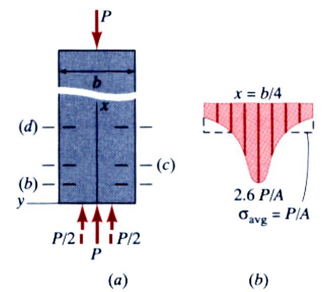
4 St. Venant s Principle The stresses and strains in a body at points that are sufficiently remote from points of application of load depend only on the static resultant of the loads and not on the distribution of the loads.
5

6
7 ζ = ELASTIC DEFORMATION OF AN AXIALLY LOADED MEMBER P (x) A (x) and ε = dδ dx Provided these quantities do not exceed the proportional limit, we can relate them using Hooke s Law, i.e. ζ = E ε P (x) A (x) δ = L 0 = E ( dδ ) dx P (x) dx A (x) E dδ = P (x) dx A (x) E Fig. 4-4 Fig. 4-2
8 EXAMPLE 1
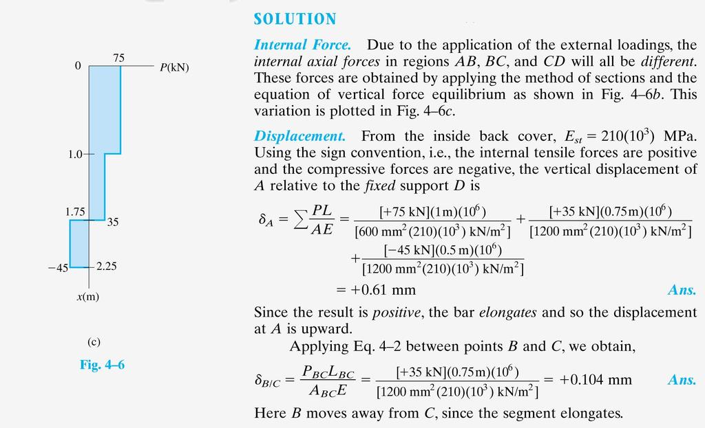
9 EXAMPLE 1 (continued)
10 PRINCIPLE OF SUPERPOSITION It can be used to simply problems having complicated loadings. This is done by dividing the loading into components, then algebraically adding the results. It is applicable provided the material obeys Hooke s Law and the deformation is small. Fig If P = P 1 + P 2 And d d 1 d 2 Then the deflection at location x is sum of two cases, ie δ x = δ x1 + δ x2
11 COMPATIBILITY CONDITIONS When the force equilibrium condition alone cannot determine the solution, the structural member is called statically indeterminate. In this case, compatibility conditions at the constraint locations shall be used to obtain the solution. For example, the stresses and elongations in the 3 steel wires are different, but their displacement at the common joint A must be the same. Fig. 4-51

12 COMPATIBILITY CONDITIONS EXAMPLE The distributed loading w= 46 kn/m is supported by three suspender bars. AB and EF are made from aluminum and CD is made from steel. If each bar has a cross-sectional area of 450 mm 2, determine the forces in each bar when the distributed loading is applied. E st =200GPa, E al = 70 Gpa.

13 FORCE METHOD OF ANALYSIS It is also possible to solve statically indeterminate problem by writing the compatibility equation using the superposition of the forces acting on the free body diagram. Fig. 4-16
14 EXAMPLE
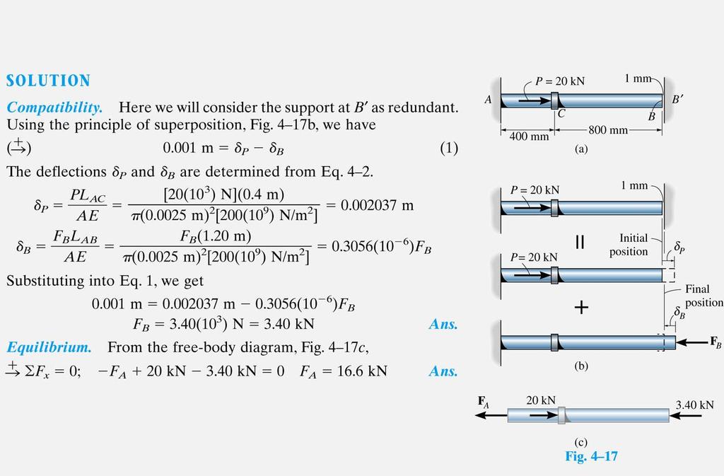
15 EXAMPLE (continued)


16 THERMAL STRESS A temperature change results in a change in length or thermal strain. There is no stress associated with the thermal strain unless the elongation is restrained by the supports. Treat the additional support as redundant and apply the principle of superposition. T T thermal T P L PL AE T L 0 expansion coef. 0 P PL AE The thermal deformation and the deformation from the redundant support must be compatible. T P 0 P AE T P ET A
17 Static Indeterminacy Structures for which internal forces and reactions cannot be determined from statics alone are said to be statically indeterminate. A structure will be statically indeterminate whenever it is held by more supports than are required to maintain its equilibrium. Redundant reactions are replaced with unknown loads which along with the other loads must produce compatible deformations. Deformations due to actual loads and redundant reactions are determined separately and then added or superposed. L R 0


18 Example Determine the reactions at A and B for the steel bar and loading shown, assuming a close fit at both supports before the loads are applied. SOLUTION: Consider the reaction at B as redundant, release the bar from that support, and solve for the displacement at B due to the applied loads. Solve for the displacement at B due to the redundant reaction at B. Require that the displacements due to the loads and due to the redundant reaction be compatible, i.e., require that their sum be zero. Solve for the reaction at A due to applied loads and the reaction found at B.


19 Example SOLUTION: Solve for the displacement at B due to the applied loads with the redundant constraint released, P A L L 0 A L 2 i 2 P i 2 L 3 P L i i A E i P L m E 9 3 N A m P 4 A Solve for the displacement at B due to the redundant constraint, P L δ 1 A 1 1 R P L 2 i 2 R P ili A E m i i B m 2 A E R B 6 m 2 N 6 m 2

20 Example Require that the displacements due to the loads and due to the redundant reaction be compatible, E R B L R E N 577kN R B 0 Find the reaction at A due to the loads and the reaction at B F R A y 0 R 323kN A 300kN 600kN 577kN R R A B 323kN 577kN
 has an outer diameter of D= 30 mm and an inner diameter of d= 22 mm. The elastic modulus of the aluminum is 70 GPa.")
21 Question # 1: Coaxial tube and core An aluminum tube (1) encases a brass core (2). The two components are bonded together to comprise an axial member that is subjected to a downward force of 30 kn. Tube (1) has an outer diameter of D= 30 mm and an inner diameter of d= 22 mm. The elastic modulus of the aluminum is 70 GPa. The brass core (2) has a diameter of D= 22 mm and an elastic modulus of 105 GPa. Compute the normal stresses in tube (1) and core (2).


22 Question # 2: Coaxial tube and core
23 Question # 3: Compound bars with temperature change The compound bar, composed of three segments shown; bronze segment [A= 2000 mm 2, E= 83 GPA: =19 x 10-6 mm/mm/c], aluminum segment [A= 1400 mm 2, E= 70 GPA: =23 x 10-6 mm/mm/c], and steel segment [A= 800 mm 2, E= 200 GPA: =11.7 x 10⁻⁶ mm/mm/c], is initially stress-free. Compute the stress in each material if the temperature drops 25C. Assume that the walls do not yield.
![Question # 4: Coaxial bars with temperature change A rectangular bar 30-mm wide and 24-mm thick made of aluminum [E= 70 GPA: =23 x 10-6 mm/mm/c] and two rectangular copper bars 30-mm wide and 12-mm](/docs-images/80/82112529/images/24-0.jpg "thick [E= 120 GPA: =16 x 10-6 mm/mm/c] are connected (in longitudinal direction) by two smooth 11-mm diameter pins.")
24 Question # 4: Coaxial bars with temperature change A rectangular bar 30-mm wide and 24-mm thick made of aluminum [E= 70 GPA: =23 x 10-6 mm/mm/c] and two rectangular copper bars 30-mm wide and 12-mm thick [E= 120 GPA: =16 x 10-6 mm/mm/c] are connected (in longitudinal direction) by two smooth 11-mm diameter pins. When the pins are initially inserted into the bars, both the copper and aluminum bars are stress free. After the temperature of the assembly has increased by 65C. (a) Determine the internal axial force in the aluminum bar. (b) Determine the normal strain in the copper bars. (c) Determine the shear stress in the 11-mm diameter pins.

25 READING QUIZ 1) The stress distributions at different cross sections are different (see figure below). Fig. 4-1 However, at locations far enough away from the support and the applied load, the stress distribution becomes uniform. This is due to A)Principle of superposition C) Poisson s effect B) Inelastic property D) Saint Venant s Principle
26 READING QUIZ 2) The principle of superposition is valid provided that a) The loading is linearly related to the stress or displacement b) The loading does not significantly change the original geometry of the member c) The Poisson s ratio v 0.45 d) Young s Modulus is small A)a, b and c C) a and b only B) a, b and d D) All

27 CONCEPT QUIZ 1) The assembly consists of two posts made from material 1 having modulus of elasticity of E 1 and a cross-sectional area A 1 and a material 2 having modulus of elasticity E 2 and crosssectional area A 2. If a central load P is applied to the rigid cap, determine the force in each post. The support is also rigid. Let r = E 1 A 1 E 2 A 2 Prob r A) P 1 = ( ) P 2r P 2 = ( ) P 2r B) P 1 = ( ) P 2r + 1 r P 2 = ( ) P 2r + 1 C) P 1 = r P P 2 = (2r-1) P D) P 1 = r (r+1) P P 2 = (r+1) P
MECHANICS OF MATERIALS
 Third CHTR Stress MCHNICS OF MTRIS Ferdinand. Beer. Russell Johnston, Jr. John T. DeWolf ecture Notes: J. Walt Oler Texas Tech University and Strain xial oading Contents Stress & Strain: xial oading Normal
CHAPTER OBJECTIVES CHAPTER OUTLINE. 4. Axial Load
 CHAPTER OBJECTIVES Determine deformation of axially loaded members Develop a method to find support reactions when it cannot be determined from euilibrium euations Analyze the effects of thermal stress
STATICALLY INDETERMINATE STRUCTURES
 STATICALLY INDETERMINATE STRUCTURES INTRODUCTION Generally the trusses are supported on (i) a hinged support and (ii) a roller support. The reaction components of a hinged support are two (in horizontal
The University of Melbourne Engineering Mechanics
 The University of Melbourne 436-291 Engineering Mechanics Tutorial Four Poisson s Ratio and Axial Loading Part A (Introductory) 1. (Problem 9-22 from Hibbeler - Statics and Mechanics of Materials) A short
MECHANICS OF MATERIALS
 CHATR Stress MCHANICS OF MATRIALS and Strain Axial Loading Stress & Strain: Axial Loading Suitability of a structure or machine may depend on the deformations in the structure as well as the stresses induced
MECHANICS OF MATERIALS
 Third E CHAPTER 2 Stress MECHANICS OF MATERIALS Ferdinand P. Beer E. Russell Johnston, Jr. John T. DeWolf Lecture Notes: J. Walt Oler Texas Tech University and Strain Axial Loading Contents Stress & Strain:
N = Shear stress / Shear strain
 UNIT - I 1. What is meant by factor of safety? [A/M-15] It is the ratio between ultimate stress to the working stress. Factor of safety = Ultimate stress Permissible stress 2. Define Resilience. [A/M-15]
MECHANICS OF MATERIALS
 Third CHTR Stress MCHNICS OF MTRIS Ferdinand. Beer. Russell Johnston, Jr. John T. DeWolf ecture Notes: J. Walt Oler Texas Tech University and Strain xial oading Contents Stress & Strain: xial oading Normal
EMA 3702 Mechanics & Materials Science (Mechanics of Materials) Chapter 2 Stress & Strain - Axial Loading
 Chapter 2 Stress & Strain - Axial Loading") MA 3702 Mechanics & Materials Science (Mechanics of Materials) Chapter 2 Stress & Strain - Axial Loading MA 3702 Mechanics & Materials Science Zhe Cheng (2018) 2 Stress & Strain - Axial Loading Statics
MA 3702 Mechanics & Materials Science (Mechanics of Materials) Chapter 2 Stress & Strain - Axial Loading MA 3702 Mechanics & Materials Science Zhe Cheng (2018) 2 Stress & Strain - Axial Loading Statics
MAAE 2202 A. Come to the PASS workshop with your mock exam complete. During the workshop you can work with other students to review your work.
 It is most beneficial to you to write this mock final exam UNDER EXAM CONDITIONS. This means: Complete the exam in 3 hours. Work on your own. Keep your textbook closed. Attempt every question. After the
Chapter 5 CENTRIC TENSION OR COMPRESSION ( AXIAL LOADING )
") Chapter 5 CENTRIC TENSION OR COMPRESSION ( AXIAL LOADING ) 5.1 DEFINITION A construction member is subjected to centric (axial) tension or compression if in any cross section the single distinct stress
Chapter 5 CENTRIC TENSION OR COMPRESSION ( AXIAL LOADING ) 5.1 DEFINITION A construction member is subjected to centric (axial) tension or compression if in any cross section the single distinct stress
INTRODUCTION TO STRAIN
 SIMPLE STRAIN INTRODUCTION TO STRAIN In general terms, Strain is a geometric quantity that measures the deformation of a body. There are two types of strain: normal strain: characterizes dimensional changes,
Mechanics of Materials II. Chapter III. A review of the fundamental formulation of stress, strain, and deflection
 Mechanics of Materials II Chapter III A review of the fundamental formulation of stress, strain, and deflection Outline Introduction Assumtions and limitations Axial loading Torsion of circular shafts
Mechanical Design in Optical Engineering. For a prismatic bar of length L in tension by axial forces P we have determined:
 Deformation of Axial Members For a prismatic bar of length L in tension by axial forces P we have determined: σ = P A δ ε = L It is important to recall that the load P must act on the centroid of the cross
Strength of Material. Shear Strain. Dr. Attaullah Shah
 Strength of Material Shear Strain Dr. Attaullah Shah Shear Strain TRIAXIAL DEFORMATION Poisson's Ratio Relationship Between E, G, and ν BIAXIAL DEFORMATION Bulk Modulus of Elasticity or Modulus of Volume
Unit I Stress and Strain
 Unit I Stress and Strain Stress and strain at a point Tension, Compression, Shear Stress Hooke s Law Relationship among elastic constants Stress Strain Diagram for Mild Steel, TOR steel, Concrete Ultimate
NORMAL STRESS. The simplest form of stress is normal stress/direct stress, which is the stress perpendicular to the surface on which it acts.
 NORMAL STRESS The simplest form of stress is normal stress/direct stress, which is the stress perpendicular to the surface on which it acts. σ = force/area = P/A where σ = the normal stress P = the centric
MECHANICS OF MATERIALS
 CHAPTER 2 MECHANICS OF MATERIALS Ferdinand P. Beer E. Russell Johnston, Jr. John T. DeWolf David F. Mazurek Lecture Notes: J. Walt Oler Texas Tech University Stress and Strain Axial Loading 2.1 An Introduction
Purpose of this Guide: To thoroughly prepare students for the exact types of problems that will be on Exam 3.
 ES230 STRENGTH OF MTERILS Exam 3 Study Guide Exam 3: Wednesday, March 8 th in-class Updated 3/3/17 Purpose of this Guide: To thoroughly prepare students for the exact types of problems that will be on
[7] Torsion. [7.1] Torsion. [7.2] Statically Indeterminate Torsion. [7] Torsion Page 1 of 21
![[7] Torsion. [7.1] Torsion. [7.2] Statically Indeterminate Torsion. [7] Torsion Page 1 of 21](/thumbs/88/115835122.jpg "[7] Torsion. [7.1] Torsion. [7.2] Statically Indeterminate Torsion. [7] Torsion Page 1 of 21") [7] Torsion Page 1 of 21 [7] Torsion [7.1] Torsion [7.2] Statically Indeterminate Torsion [7] Torsion Page 2 of 21 [7.1] Torsion SHEAR STRAIN DUE TO TORSION 1) A shaft with a circular cross section is
[7] Torsion Page 1 of 21 [7] Torsion [7.1] Torsion [7.2] Statically Indeterminate Torsion [7] Torsion Page 2 of 21 [7.1] Torsion SHEAR STRAIN DUE TO TORSION 1) A shaft with a circular cross section is
Free Body Diagram: Solution: The maximum load which can be safely supported by EACH of the support members is: ANS: A =0.217 in 2
 Problem 10.9 The angle β of the system in Problem 10.8 is 60. The bars are made of a material that will safely support a tensile normal stress of 8 ksi. Based on this criterion, if you want to design the
ME 243. Mechanics of Solids
 ME 243 Mechanics of Solids Lecture 2: Stress and Strain Ahmad Shahedi Shakil Lecturer, Dept. of Mechanical Engg, BUET E-mail: sshakil@me.buet.ac.bd, shakil6791@gmail.com Website: teacher.buet.ac.bd/sshakil
4.MECHANICAL PROPERTIES OF MATERIALS
 4.MECHANICAL PROPERTIES OF MATERIALS The diagram representing the relation between stress and strain in a given material is an important characteristic of the material. To obtain the stress-strain diagram
CHAPTER 5 Statically Determinate Plane Trusses
 CHAPTER 5 Statically Determinate Plane Trusses TYPES OF ROOF TRUSS TYPES OF ROOF TRUSS ROOF TRUSS SETUP ROOF TRUSS SETUP OBJECTIVES To determine the STABILITY and DETERMINACY of plane trusses To analyse
CHAPTER 5 Statically Determinate Plane Trusses TYPES OF ROOF TRUSS
 CHAPTER 5 Statically Determinate Plane Trusses TYPES OF ROOF TRUSS 1 TYPES OF ROOF TRUSS ROOF TRUSS SETUP 2 ROOF TRUSS SETUP OBJECTIVES To determine the STABILITY and DETERMINACY of plane trusses To analyse
RODS: THERMAL STRESS AND STRESS CONCENTRATION
 RODS: HERML SRESS ND SRESS CONCENRION Example 5 rod of length L, cross-sectional area, and modulus of elasticity E, has been placed inside a tube of the same length L, but of cross-sectional area and modulus
CHAPTER 4: BENDING OF BEAMS
 (74) CHAPTER 4: BENDING OF BEAMS This chapter will be devoted to the analysis of prismatic members subjected to equal and opposite couples M and M' acting in the same longitudinal plane. Such members are
RODS: STATICALLY INDETERMINATE MEMBERS
 RODS: STTICLLY INDETERMINTE MEMERS Statically Indeterminate ackground In all of the problems discussed so far, it was possible to determine the forces and stresses in the members by utilizing the equations
Samantha Ramirez, MSE. Stress. The intensity of the internal force acting on a specific plane (area) passing through a point. F 2
 passing through a point. F 2") Samantha Ramirez, MSE Stress The intensity of the internal force acting on a specific plane (area) passing through a point. Δ ΔA Δ z Δ 1 2 ΔA Δ x Δ y ΔA is an infinitesimal size area with a uniform force
Samantha Ramirez, MSE Stress The intensity of the internal force acting on a specific plane (area) passing through a point. Δ ΔA Δ z Δ 1 2 ΔA Δ x Δ y ΔA is an infinitesimal size area with a uniform force
[5] Stress and Strain
![[5] Stress and Strain](/thumbs/95/123344550.jpg "[5] Stress and Strain") [5] Stress and Strain Page 1 of 34 [5] Stress and Strain [5.1] Internal Stress of Solids [5.2] Design of Simple Connections (will not be covered in class) [5.3] Deformation and Strain [5.4] Hooke s Law
[5] Stress and Strain Page 1 of 34 [5] Stress and Strain [5.1] Internal Stress of Solids [5.2] Design of Simple Connections (will not be covered in class) [5.3] Deformation and Strain [5.4] Hooke s Law
MECE 3321 MECHANICS OF SOLIDS CHAPTER 3
 MECE 3321 MECHANICS OF SOLIDS CHAPTER 3 Samantha Ramirez TENSION AND COMPRESSION TESTS Tension and compression tests are used primarily to determine the relationship between σ avg and ε avg in any material.
Chapter Two: Mechanical Properties of materials
 Chapter Two: Mechanical Properties of materials Time : 16 Hours An important consideration in the choice of a material is the way it behave when subjected to force. The mechanical properties of a material
Strength of Materials (15CV 32)
") Strength of Materials (15CV 32) Module 1 : Simple Stresses and Strains Dr. H. Ananthan, Professor, VVIET,MYSURU 8/21/2017 Introduction, Definition and concept and of stress and strain. Hooke s law, Stress-Strain
Strength of Materials (15CV 32) Module 1 : Simple Stresses and Strains Dr. H. Ananthan, Professor, VVIET,MYSURU 8/21/2017 Introduction, Definition and concept and of stress and strain. Hooke s law, Stress-Strain
Downloaded from Downloaded from / 1
 PURWANCHAL UNIVERSITY III SEMESTER FINAL EXAMINATION-2002 LEVEL : B. E. (Civil) SUBJECT: BEG256CI, Strength of Material Full Marks: 80 TIME: 03:00 hrs Pass marks: 32 Candidates are required to give their
PES Institute of Technology
 PES Institute of Technology Bangalore south campus, Bangalore-5460100 Department of Mechanical Engineering Faculty name : Madhu M Date: 29/06/2012 SEM : 3 rd A SEC Subject : MECHANICS OF MATERIALS Subject
The problem of transmitting a torque or rotary motion from one plane to another is frequently encountered in machine design.
 CHAPER ORSION ORSION orsion refers to the twisting of a structural member when it is loaded by moments/torques that produce rotation about the longitudinal axis of the member he problem of transmitting
ME Final Exam. PROBLEM NO. 4 Part A (2 points max.) M (x) y. z (neutral axis) beam cross-sec+on. 20 kip ft. 0.2 ft. 10 ft. 0.1 ft.
 M (x) y. z (neutral axis) beam cross-sec+on. 20 kip ft. 0.2 ft. 10 ft. 0.1 ft.") ME 323 - Final Exam Name December 15, 2015 Instructor (circle) PROEM NO. 4 Part A (2 points max.) Krousgrill 11:30AM-12:20PM Ghosh 2:30-3:20PM Gonzalez 12:30-1:20PM Zhao 4:30-5:20PM M (x) y 20 kip ft 0.2
ME 323 - Final Exam Name December 15, 2015 Instructor (circle) PROEM NO. 4 Part A (2 points max.) Krousgrill 11:30AM-12:20PM Ghosh 2:30-3:20PM Gonzalez 12:30-1:20PM Zhao 4:30-5:20PM M (x) y 20 kip ft 0.2
KINGS COLLEGE OF ENGINEERING DEPARTMENT OF MECHANICAL ENGINEERING QUESTION BANK. Subject code/name: ME2254/STRENGTH OF MATERIALS Year/Sem:II / IV
 KINGS COLLEGE OF ENGINEERING DEPARTMENT OF MECHANICAL ENGINEERING QUESTION BANK Subject code/name: ME2254/STRENGTH OF MATERIALS Year/Sem:II / IV UNIT I STRESS, STRAIN DEFORMATION OF SOLIDS PART A (2 MARKS)
Stress Analysis Lecture 3 ME 276 Spring Dr./ Ahmed Mohamed Nagib Elmekawy
 Stress Analysis Lecture 3 ME 276 Spring 2017-2018 Dr./ Ahmed Mohamed Nagib Elmekawy Axial Stress 2 Beam under the action of two tensile forces 3 Beam under the action of two tensile forces 4 Shear Stress
STRESS, STRAIN AND DEFORMATION OF SOLIDS
 VELAMMAL COLLEGE OF ENGINEERING AND TECHNOLOGY, MADURAI 625009 DEPARTMENT OF CIVIL ENGINEERING CE8301 STRENGTH OF MATERIALS I -------------------------------------------------------------------------------------------------------------------------------
ME 323 Examination #2 April 11, 2018
 ME 2 Eamination #2 April, 2 PROBLEM NO. 25 points ma. A thin-walled pressure vessel is fabricated b welding together two, open-ended stainless-steel vessels along a 6 weld line. The welded vessel has an
CHAPTER 3 THE EFFECTS OF FORCES ON MATERIALS
 CHAPTER THE EFFECTS OF FORCES ON MATERIALS EXERCISE 1, Page 50 1. A rectangular bar having a cross-sectional area of 80 mm has a tensile force of 0 kn applied to it. Determine the stress in the bar. Stress
Direct and Shear Stress
 Direct and Shear Stress 1 Direct & Shear Stress When a body is pulled by a tensile force or crushed by a compressive force, the loading is said to be direct. Direct stresses are also found to arise when
STRENGTH OF MATERIALS-I. Unit-1. Simple stresses and strains
 STRENGTH OF MATERIALS-I Unit-1 Simple stresses and strains 1. What is the Principle of surveying 2. Define Magnetic, True & Arbitrary Meridians. 3. Mention different types of chains 4. Differentiate between
five Mechanics of Materials 1 ARCHITECTURAL STRUCTURES: FORM, BEHAVIOR, AND DESIGN DR. ANNE NICHOLS SUMMER 2017 lecture
 ARCHITECTURAL STRUCTURES: FORM, BEHAVIOR, AND DESIGN DR. ANNE NICHOLS SUMMER 2017 lecture five mechanics www.carttalk.com of materials Mechanics of Materials 1 Mechanics of Materials MECHANICS MATERIALS
Aluminum shell. Brass core. 40 in
 PROBLEM #1 (22 points) A solid brass core is connected to a hollow rod made of aluminum. Both are attached at each end to a rigid plate as shown in Fig. 1. The moduli of aluminum and brass are EA=11,000
Module 2. Analysis of Statically Indeterminate Structures by the Matrix Force Method
 Module 2 Analysis of Statically Indeterminate Structures by the Matrix Force Method Lesson 10 The Force Method of Analysis: Trusses Instructional Objectives After reading this chapter the student will
Theory at a Glance (for IES, GATE, PSU)
") 1. Stress and Strain Theory at a Glance (for IES, GATE, PSU) 1.1 Stress () When a material is subjected to an external force, a resisting force is set up within the component. The internal resistance force
1. Stress and Strain Theory at a Glance (for IES, GATE, PSU) 1.1 Stress () When a material is subjected to an external force, a resisting force is set up within the component. The internal resistance force
Mechanics of Solids. Mechanics Of Solids. Suraj kr. Ray Department of Civil Engineering
 Mechanics Of Solids Suraj kr. Ray (surajjj2445@gmail.com) Department of Civil Engineering 1 Mechanics of Solids is a branch of applied mechanics that deals with the behaviour of solid bodies subjected
UNIT-I STRESS, STRAIN. 1. A Member A B C D is subjected to loading as shown in fig determine the total elongation. Take E= 2 x10 5 N/mm 2
 UNIT-I STRESS, STRAIN 1. A Member A B C D is subjected to loading as shown in fig determine the total elongation. Take E= 2 x10 5 N/mm 2 Young s modulus E= 2 x10 5 N/mm 2 Area1=900mm 2 Area2=400mm 2 Area3=625mm
Problem " Â F y = 0. ) R A + 2R B + R C = 200 kn ) 2R A + 2R B = 200 kn [using symmetry R A = R C ] ) R A + R B = 100 kn
![Problem  F y = 0. ) R A + 2R B + R C = 200 kn ) 2R A + 2R B = 200 kn [using symmetry R A = R C ] ) R A + R B = 100 kn](/thumbs/88/116790835.jpg "Problem  F y = 0. ) R A + 2R B + R C = 200 kn ) 2R A + 2R B = 200 kn [using symmetry R A = R C ] ) R A + R B = 100 kn") Problem 0. Three cables are attached as shown. Determine the reactions in the supports. Assume R B as redundant. Also, L AD L CD cos 60 m m. uation of uilibrium: + "  F y 0 ) R A cos 60 + R B + R C cos
Problem 0. Three cables are attached as shown. Determine the reactions in the supports. Assume R B as redundant. Also, L AD L CD cos 60 m m. uation of uilibrium: + " Â F y 0 ) R A cos 60 + R B + R C cos
MECHANICS OF MATERIALS
 STATICS AND MECHANICS OF MATERIALS Ferdinand P. Beer E. Russell Johnston, Jr, John T. DeWolf David E Mazurek \Cawect Mc / iur/» Craw SugomcT Hilt Introduction 1 1.1 What is Mechanics? 2 1.2 Fundamental
UNIT I SIMPLE STRESSES AND STRAINS
 Subject with Code : SM-1(15A01303) Year & Sem: II-B.Tech & I-Sem SIDDHARTH GROUP OF INSTITUTIONS :: PUTTUR Siddharth Nagar, Narayanavanam Road 517583 QUESTION BANK (DESCRIPTIVE) UNIT I SIMPLE STRESSES
UNIT 1 STRESS STRAIN AND DEFORMATION OF SOLIDS, STATES OF STRESS 1. Define stress. When an external force acts on a body, it undergoes deformation.
 UNIT 1 STRESS STRAIN AND DEFORMATION OF SOLIDS, STATES OF STRESS 1. Define stress. When an external force acts on a body, it undergoes deformation. At the same time the body resists deformation. The magnitude
R13. II B. Tech I Semester Regular Examinations, Jan MECHANICS OF SOLIDS (Com. to ME, AME, AE, MTE) PART-A
 PART-A") SET - 1 II B. Tech I Semester Regular Examinations, Jan - 2015 MECHANICS OF SOLIDS (Com. to ME, AME, AE, MTE) Time: 3 hours Max. Marks: 70 Note: 1. Question Paper consists of two parts (Part-A and Part-B)
SET - 1 II B. Tech I Semester Regular Examinations, Jan - 2015 MECHANICS OF SOLIDS (Com. to ME, AME, AE, MTE) Time: 3 hours Max. Marks: 70 Note: 1. Question Paper consists of two parts (Part-A and Part-B)
Torsion of Shafts Learning objectives
 Torsion of Shafts Shafts are structural members with length significantly greater than the largest cross-sectional dimension used in transmitting torque from one plane to another. Learning objectives Understand
Mechanical Properties of Materials
 Mechanical Properties of Materials Strains Material Model Stresses Learning objectives Understand the qualitative and quantitative description of mechanical properties of materials. Learn the logic of
EMA 3702 Mechanics & Materials Science (Mechanics of Materials) Chapter 3 Torsion
 Chapter 3 Torsion") EMA 3702 Mechanics & Materials Science (Mechanics of Materials) Chapter 3 Torsion Introduction Stress and strain in components subjected to torque T Circular Cross-section shape Material Shaft design Non-circular
EMA 3702 Mechanics & Materials Science (Mechanics of Materials) Chapter 3 Torsion Introduction Stress and strain in components subjected to torque T Circular Cross-section shape Material Shaft design Non-circular
M. Vable Mechanics of Materials: Chapter 5. Torsion of Shafts
 Torsion of Shafts Shafts are structural members with length significantly greater than the largest cross-sectional dimension used in transmitting torque from one plane to another. Learning objectives Understand
QUESTION BANK SEMESTER: III SUBJECT NAME: MECHANICS OF SOLIDS
 QUESTION BANK SEMESTER: III SUBJECT NAME: MECHANICS OF SOLIDS UNIT 1- STRESS AND STRAIN PART A (2 Marks) 1. Define longitudinal strain and lateral strain. 2. State Hooke s law. 3. Define modular ratio,
QUESTION BANK DEPARTMENT: CIVIL SEMESTER: III SUBJECT CODE: CE2201 SUBJECT NAME: MECHANICS OF SOLIDS UNIT 1- STRESS AND STRAIN PART A
 DEPARTMENT: CIVIL SUBJECT CODE: CE2201 QUESTION BANK SEMESTER: III SUBJECT NAME: MECHANICS OF SOLIDS UNIT 1- STRESS AND STRAIN PART A (2 Marks) 1. Define longitudinal strain and lateral strain. 2. State
PDDC 1 st Semester Civil Engineering Department Assignments of Mechanics of Solids [ ] Introduction, Fundamentals of Statics
![PDDC 1 st Semester Civil Engineering Department Assignments of Mechanics of Solids [ ] Introduction, Fundamentals of Statics](/thumbs/92/109382806.jpg "PDDC 1 st Semester Civil Engineering Department Assignments of Mechanics of Solids [ ] Introduction, Fundamentals of Statics") Page1 PDDC 1 st Semester Civil Engineering Department Assignments of Mechanics of Solids [2910601] Introduction, Fundamentals of Statics 1. Differentiate between Scalar and Vector quantity. Write S.I.
Page1 PDDC 1 st Semester Civil Engineering Department Assignments of Mechanics of Solids [2910601] Introduction, Fundamentals of Statics 1. Differentiate between Scalar and Vector quantity. Write S.I.
Unit M1.5 Statically Indeterminate Systems
 Unit M1.5 Statically Indeterminate Systems Readings: CDL 2.1, 2.3, 2.4, 2.7 16.001/002 -- Unified Engineering Department of Aeronautics and Astronautics Massachusetts Institute of Technology LEARNING OBJECTIVES
Name (Print) ME Mechanics of Materials Exam # 1 Date: October 5, 2016 Time: 8:00 10:00 PM
 ME Mechanics of Materials Exam # 1 Date: October 5, 2016 Time: 8:00 10:00 PM") Name (Print) (Last) (First) Instructions: ME 323 - Mechanics of Materials Exam # 1 Date: October 5, 2016 Time: 8:00 10:00 PM Circle your lecturer s name and your class meeting time. Gonzalez Krousgrill
Name (Print) (Last) (First) Instructions: ME 323 - Mechanics of Materials Exam # 1 Date: October 5, 2016 Time: 8:00 10:00 PM Circle your lecturer s name and your class meeting time. Gonzalez Krousgrill
Mechanical Engineering Ph.D. Preliminary Qualifying Examination Solid Mechanics February 25, 2002
 student personal identification (ID) number on each sheet. Do not write your name on any sheet. #1. A homogeneous, isotropic, linear elastic bar has rectangular cross sectional area A, modulus of elasticity
Problem d d d B C E D. 0.8d. Additional lecturebook examples 29 ME 323
 Problem 9.1 Two beam segments, AC and CD, are connected together at C by a frictionless pin. Segment CD is cantilevered from a rigid support at D, and segment AC has a roller support at A. a) Determine
Solution: T, A1, A2, A3, L1, L2, L3, E1, E2, E3, P are known Five equations in five unknowns, F1, F2, F3, ua and va
 ME 323 Examination # 1 February 18, 2016 Name (Print) (Last) (First) Instructor PROBLEM #1 (20 points) A structure is constructed from members 1, 2 and 3, with these members made up of the same material
Class XI Chapter 9 Mechanical Properties of Solids Physics
 Book Name: NCERT Solutions Question : A steel wire of length 4.7 m and cross-sectional area 5 3.0 0 m stretches by the same 5 amount as a copper wire of length 3.5 m and cross-sectional area of 4.0 0 m
QUESTION BANK ENGINEERS ACADEMY. PL 4Ed d. Ed d. 4PL Ed d. 4Ed d. 42 Axially Loaded Members Junior Engineer
 NGINRS CDMY xially oaded Members Junior ngineer QUSTION BNK 1. The stretch in a steel rod of circular section, having a length subjected to a tensile load P and tapering uniformly from a diameter d 1 at
Symmetric Bending of Beams
 Symmetric Bending of Beams beam is any long structural member on which loads act perpendicular to the longitudinal axis. Learning objectives Understand the theory, its limitations and its applications
6.4 A cylindrical specimen of a titanium alloy having an elastic modulus of 107 GPa ( psi) and
 and") 6.4 A cylindrical specimen of a titanium alloy having an elastic modulus of 107 GPa (15.5 10 6 psi) and an original diameter of 3.8 mm (0.15 in.) will experience only elastic deformation when a tensile
6.4 A cylindrical specimen of a titanium alloy having an elastic modulus of 107 GPa (15.5 10 6 psi) and an original diameter of 3.8 mm (0.15 in.) will experience only elastic deformation when a tensile
Mechanics of Materials Primer
 Mechanics of Materials rimer Notation: A = area (net = with holes, bearing = in contact, etc...) b = total width of material at a horizontal section d = diameter of a hole D = symbol for diameter E = modulus
Constitutive Equations (Linear Elasticity)
") Constitutive quations (Linear lasticity) quations that characterize the physical properties of the material of a system are called constitutive equations. It is possible to find the applied stresses knowing
Constitutive quations (Linear lasticity) quations that characterize the physical properties of the material of a system are called constitutive equations. It is possible to find the applied stresses knowing
Russell C. Hibbeler. Chapter 1: Stress
 Russell C. Hibbeler Chapter 1: Stress Introduction Mechanics of materials is a study of the relationship between the external loads on a body and the intensity of the internal loads within the body. This
D : SOLID MECHANICS. Q. 1 Q. 9 carry one mark each. Q.1 Find the force (in kn) in the member BH of the truss shown.
 in the member BH of the truss shown.") D : SOLID MECHANICS Q. 1 Q. 9 carry one mark each. Q.1 Find the force (in kn) in the member BH of the truss shown. Q.2 Consider the forces of magnitude F acting on the sides of the regular hexagon having
D : SOLID MECHANICS Q. 1 Q. 9 carry one mark each. Q.1 Find the force (in kn) in the member BH of the truss shown. Q.2 Consider the forces of magnitude F acting on the sides of the regular hexagon having
Advanced Structural Analysis EGF Section Properties and Bending
 Advanced Structural Analysis EGF316 3. Section Properties and Bending 3.1 Loads in beams When we analyse beams, we need to consider various types of loads acting on them, for example, axial forces, shear
2012 MECHANICS OF SOLIDS
 R10 SET - 1 II B.Tech II Semester, Regular Examinations, April 2012 MECHANICS OF SOLIDS (Com. to ME, AME, MM) Time: 3 hours Max. Marks: 75 Answer any FIVE Questions All Questions carry Equal Marks ~~~~~~~~~~~~~~~~~~~~~~
 Question 9.1: A steel wire of length 4.7 m and cross-sectional area 3.0 10 5 m 2 stretches by the same amount as a copper wire of length 3.5 m and cross-sectional area of 4.0 10 5 m 2 under a given load.
Name :. Roll No. :... Invigilator s Signature :.. CS/B.TECH (CE-NEW)/SEM-3/CE-301/ SOLID MECHANICS
/SEM-3/CE-301/ SOLID MECHANICS") Name :. Roll No. :..... Invigilator s Signature :.. 2011 SOLID MECHANICS Time Allotted : 3 Hours Full Marks : 70 The figures in the margin indicate full marks. Candidates are required to give their answers
Name :. Roll No. :..... Invigilator s Signature :.. 2011 SOLID MECHANICS Time Allotted : 3 Hours Full Marks : 70 The figures in the margin indicate full marks. Candidates are required to give their answers
Torsion Stresses in Tubes and Rods
 Torsion Stresses in Tubes and Rods This initial analysis is valid only for a restricted range of problem for which the assumptions are: Rod is initially straight. Rod twists without bending. Material is
Strength of Materials Prof S. K. Bhattacharya Department of Civil Engineering Indian Institute of Technology, Kharagpur Lecture - 18 Torsion - I
 Strength of Materials Prof S. K. Bhattacharya Department of Civil Engineering Indian Institute of Technology, Kharagpur Lecture - 18 Torsion - I Welcome to the first lesson of Module 4 which is on Torsion
BEAM A horizontal or inclined structural member that is designed to resist forces acting to its axis is called a beam
 BEM horizontal or inclined structural member that is designed to resist forces acting to its axis is called a beam INTERNL FORCES IN BEM Whether or not a beam will break, depend on the internal resistances
STANDARD SAMPLE. Reduced section " Diameter. Diameter. 2" Gauge length. Radius
 MATERIAL PROPERTIES TENSILE MEASUREMENT F l l 0 A 0 F STANDARD SAMPLE Reduced section 2 " 1 4 0.505" Diameter 3 4 " Diameter 2" Gauge length 3 8 " Radius TYPICAL APPARATUS Load cell Extensometer Specimen
MECE 3321: MECHANICS OF SOLIDS CHAPTER 5
 MECE 3321: MECHANICS OF SOLIDS CHAPTER 5 SAMANTHA RAMIREZ TORSION Torque A moment that tends to twist a member about its longitudinal axis 1 TORSIONAL DEFORMATION OF A CIRCULAR SHAFT Assumption If the
UNIVERSITY OF SASKATCHEWAN ME MECHANICS OF MATERIALS I FINAL EXAM DECEMBER 13, 2008 Professor A. Dolovich
 UNIVERSITY OF SASKATCHEWAN ME 313.3 MECHANICS OF MATERIALS I FINAL EXAM DECEMBER 13, 2008 Professor A. Dolovich A CLOSED BOOK EXAMINATION TIME: 3 HOURS For Marker s Use Only LAST NAME (printed): FIRST
Module 4 : Deflection of Structures Lecture 4 : Strain Energy Method
 Module 4 : Deflection of Structures Lecture 4 : Strain Energy Method Objectives In this course you will learn the following Deflection by strain energy method. Evaluation of strain energy in member under
9 MECHANICAL PROPERTIES OF SOLIDS
 9 MECHANICAL PROPERTIES OF SOLIDS Deforming force Deforming force is the force which changes the shape or size of a body. Restoring force Restoring force is the internal force developed inside the body
Chapter 11. Displacement Method of Analysis Slope Deflection Method
 Chapter 11 Displacement ethod of Analysis Slope Deflection ethod Displacement ethod of Analysis Two main methods of analyzing indeterminate structure Force method The method of consistent deformations
Stress-Strain Behavior
 Stress-Strain Behavior 6.3 A specimen of aluminum having a rectangular cross section 10 mm 1.7 mm (0.4 in. 0.5 in.) is pulled in tension with 35,500 N (8000 lb f ) force, producing only elastic deformation.
ISHIK UNIVERSITY DEPARTMENT OF MECHATRONICS ENGINEERING
 ISHIK UNIVERSITY DEPARTMENT OF MECHATRONICS ENGINEERING QUESTION BANK FOR THE MECHANICS OF MATERIALS-I 1. A rod 150 cm long and of diameter 2.0 cm is subjected to an axial pull of 20 kn. If the modulus
Chapter 4 Deflection and Stiffness
 Chapter 4 Deflection and Stiffness Asst. Prof. Dr. Supakit Rooppakhun Chapter Outline Deflection and Stiffness 4-1 Spring Rates 4-2 Tension, Compression, and Torsion 4-3 Deflection Due to Bending 4-4 Beam
2. Trusses and bars in axial load Contents
 2. Trusses and bars in axial load Contents 2. Trusses and bars in axial load... 1 2.1 Introduction... 2 2.2 Physics re-cap: spring mechanics... 3 2.3 Statics: Equilibrium of internal and external forces
(48) CHAPTER 3: TORSION
 CHAPTER 3: TORSION") (48) CHAPTER 3: TORSION Introduction: In this chapter structural members and machine parts that are in torsion will be considered. More specifically, you will analyze the stresses and strains in members
(48) CHAPTER 3: TORSION Introduction: In this chapter structural members and machine parts that are in torsion will be considered. More specifically, you will analyze the stresses and strains in members
Indeterminate Analysis Force Method 1
 Indeterminate Analysis Force Method 1 The force (flexibility) method expresses the relationships between displacements and forces that exist in a structure. Primary objective of the force method is to
SRI CHANDRASEKHARENDRA SARASWATHI VISWA MAHAVIDHYALAYA
 SRI CHANDRASEKHARENDRA SARASWATHI VISWA MAHAVIDHYALAYA (Declared as Deemed-to-be University under Section 3 of the UGC Act, 1956, Vide notification No.F.9.9/92-U-3 dated 26 th May 1993 of the Govt. of
March 24, Chapter 4. Deflection and Stiffness. Dr. Mohammad Suliman Abuhaiba, PE
 Chapter 4 Deflection and Stiffness 1 2 Chapter Outline Spring Rates Tension, Compression, and Torsion Deflection Due to Bending Beam Deflection Methods Beam Deflections by Superposition Strain Energy Castigliano
IDE 110 Mechanics of Materials Spring 2006 Final Examination FOR GRADING ONLY
 Spring 2006 Final Examination STUDENT S NAME (please print) STUDENT S SIGNATURE STUDENT NUMBER IDE 110 CLASS SECTION INSTRUCTOR S NAME Do not turn this page until instructed to start. Write your name on
Reg. No. : Question Paper Code : B.Arch. DEGREE EXAMINATION, APRIL/MAY Second Semester AR 6201 MECHANICS OF STRUCTURES I
 WK 4 Reg. No. : Question Paper Code : 71387 B.Arch. DEGREE EXAMINATION, APRIL/MAY 2017. Second Semester AR 6201 MECHANICS OF STRUCTURES I (Regulations 2013) Time : Three hours Maximum : 100 marks Answer
18.Define the term modulus of resilience. May/June Define Principal Stress. 20. Define Hydrostatic Pressure.
 CE6306 STREGNTH OF MATERIALS Question Bank Unit-I STRESS, STRAIN, DEFORMATION OF SOLIDS PART-A 1. Define Poison s Ratio May/June 2009 2. What is thermal stress? May/June 2009 3. Estimate the load carried
Question Figure shows the strain-stress curve for a given material. What are (a) Young s modulus and (b) approximate yield strength for this material?
 Young s modulus and (b) approximate yield strength for this material?") Question. A steel wire of length 4.7 m and cross-sectional area 3.0 x 10⁻⁵ m 2 stretches by the same amount as a copper wire of length 3.5 m and cross-sectional area of 4.0 x 10⁻⁵ m 2 under a given load.
Question. A steel wire of length 4.7 m and cross-sectional area 3.0 x 10⁻⁵ m 2 stretches by the same amount as a copper wire of length 3.5 m and cross-sectional area of 4.0 x 10⁻⁵ m 2 under a given load.