MECHANICS OF MATERIALS
|
|
|
- Joleen Chandler
- 5 years ago
- Views:
Transcription
1 Third CHTR Stress MCHNICS OF MTRIS Ferdinand. Beer. Russell Johnston, Jr. John T. DeWolf ecture Notes: J. Walt Oler Texas Tech University and Strain xial oading
2 Contents Stress & Strain: xial oading Normal Strain Stress-Strain Test Stress-Strain Diagram: Ductile Materials Stress-Strain Diagram: Brittle Materials Hooke s aw: Modulus of lasticity lastic vs. lastic Behavior Fatigue Deformations Under xial oading xample.01 Sample roblem.1 Static Indeterminacy xample.04 Thermal Stresses oisson s Ratio Generalized Hooke s aw Dilatation: Bulk Modulus Shearing Strain xample.10 Relation mong, n, and G Sample roblem.5 Composite Materials Saint-Venant s rinciple Stress Concentration: Hole Stress Concentration: Fillet xample.1 lastoplastic Materials lastic Deformations Residual Stresses xample.14,.15,.16 -
3 Stress & Strain: xial oading Suitability of a structure or machine may depend on the deformations in the structure as well as the stresses induced under loading. Statics analyses alone are not sufficient. Considering structures as deformable allows determination of member forces and reactions which are statically indeterminate. Determination of the stress distribution within a member also requires consideration of deformations in the member. Chapter is concerned with deformation of a structural member under axial loading. ater chapters will deal with torsional and pure bending loads. -


4 Normal Strain stress normal strain - 4
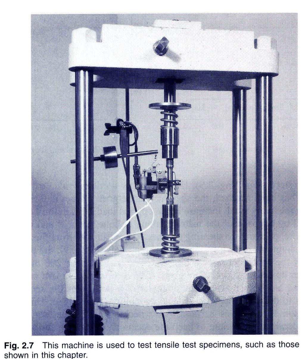
5 Stress-Strain Test - 5

6 Stress-Strain Diagram: Ductile Materials - 6

7 Stress-Strain Diagram: Brittle Materials - 7
8 Hooke s aw: Modulus of lasticity Below the yield stress Youngs Modulus or Modulus of lasticity Strength is affected by alloying, heat treating, and manufacturing process but stiffness (Modulus of lasticity) is not. - 8
9 lastic vs. lastic Behavior If the strain disappears when the stress is removed, the material is said to behave elastically. The largest stress for which this occurs is called the elastic limit. When the strain does not return to zero after the stress is removed, the material is said to behave plastically. - 9
10 Deformations Under xial oading From Hooke s aw: From the definition of strain: quating and solving for the deformation, With variations in loading, cross-section or material properties, i i i i i - 10

11 xample psi D 1.07in. d 0.618in. SOUTION: Divide the rod into components at the load application points. pply a free-body analysis on each component to determine the internal force Determine the deformation of the steel rod shown under the given loads. valuate the total of the component deflections. - 11

12 SOUTION: Divide the rod into three components: pply free-body analysis to each component to determine internal forces, lb lb lb valuate total deflection, i i i i i in in. 0.9 in 16in. 0.in in. - 1
13 Sample roblem.1 SOUTION: The rigid bar BD is supported by two links B and CD. ink B is made of aluminum ( = 70 Ga) and has a cross-sectional area of 500 mm. ink CD is made of steel ( = 00 Ga) and has a cross-sectional area of (600 mm ). For the 0-kN force shown, determine the deflection a) of B, b) of D, and c) of. pply a free-body analysis to the bar BD to find the forces exerted by links B and DC. valuate the deformation of links B and DC or the displacements of B and D. Work out the geometry to find the deflection at given the deflections at B and D. - 1
14 Sample roblem.1 SOUTION: Free body: Bar BD Displacement of B: B 6010 N 0.m m 7010 a m M F F B 0 M CD D 0 B 0 0kN 0.6m 0 0kN 0.4m F 90kN tension F CD B 60kN compression 0.m 0.m Displacement of D: D B 0.514mm 9010 N 0.4m m 0010 a m D 0.00mm - 14
15 Sample roblem.1 Displacement of D: BB DD BH HD 0.514mm 0.00 mm x 7.7 mm 00mm x x DD 0.00mm H HD 1.98mm mm 7.7 mm 1.98mm - 15
16 Static Indeterminacy Structures for which internal forces and reactions cannot be determined from statics alone are said to be statically indeterminate. structure will be statically indeterminate whenever it is held by more supports than are required to maintain its equilibrium. Redundant reactions are replaced with unknown loads which along with the other loads must produce compatible deformations. Deformations due to actual loads and redundant reactions are determined separately and then added or superposed. R 0-16


17 xample.04 Determine the reactions at and B for the steel bar and loading shown, assuming a close fit at both supports before the loads are applied. SOUTION: Consider the reaction at B as redundant, release the bar from that support, and solve for the displacement at B due to the applied loads. Solve for the displacement at B due to the redundant reaction at B. Require that the displacements due to the loads and due to the redundant reaction be compatible, i.e., require that their sum be zero. Solve for the reaction at due to applied loads and the reaction found at B. - 17


18 xample.04 SOUTION: Solve for the displacement at B due to the applied loads with the redundant constraint released, i i i i i m N 0.150m Solve for the displacement at B due to the redundant constraint, δ R i R ii m i i B m R B 6 m N 6 m - 18

19 xample.04 Require that the displacements due to the loads and due to the redundant reaction be compatible, R B R N 577kN R B 0 Find the reaction at due to the loads and the reaction at B F R y 0 R kn 00kN 600kN 577kN R R B kn 577kN - 19


20 Thermal Stresses temperature change results in a change in length or thermal strain. There is no stress associated with the thermal strain unless the elongation is restrained by the supports. Treat the adal support as redundant and apply the principle of superposition. T T thermal T T 0 expansion coef. 0 The thermal deformation and the deformation from the redundant support must be compatible. T 0 T T - 0

, y z 0")
21 oisson s Ratio For a slender bar subjected to axial loading: x x y z 0 The elongation in the x-direction is accompanied by a contraction in the other directions. ssuming that the material is isotropic (no directional dependence), y z 0 oisson s ratio is defined as lateralstrain y n axial strain x z x - 1
22 Generalized Hooke s aw For an element subjected to multi-axial loading, the normal strain components resulting from the stress components may be determined from the principle of superposition. This requires: 1) strain is linearly related to stress ) deformations are small With these restrictions: x y z n x y n z n x y n z n n x y z -
23 Shearing Strain cubic element subjected to a shear stress will deform into a rhomboid. The corresponding shear strain is quantified in terms of the change in angle between the sides, xy f xy plot of shear stress vs. shear strain is similar the previous plots of normal stress vs. normal strain except that the strength values are approximately half. For small strains, xy G xy yz G yz zx G where G is the modulus of rigidity or shear modulus. zx -

24 xample.10 rectangular block of material with modulus of rigidity G = 90 ksi is bonded to two rigid horizontal plates. The lower plate is fixed, while the upper plate is subjected to a horizontal force. Knowing that the upper plate moves through 0.04 in. under the action of the force, determine a) the average shearing strain in the material, and b) the force exerted on the plate. SOUTION: Determine the average angular deformation or shearing strain of the block. pply Hooke s law for shearing stress and strain to find the corresponding shearing stress. Use the definition of shearing stress to find the force. - 4

25 Determine the average angular deformation or shearing strain of the block. xy tan xy 0.04in. in. xy 0.00rad pply Hooke s law for shearing stress and strain to find the corresponding shearing stress. xy G 9010 psi 0.00rad 1800psi xy Use the definition of shearing stress to find the force. 1800psi8in..5in. 610 lb xy 6.0kips - 5

26 Sample roblem.5 circle of diameter d = 9 in. is scribed on an unstressed aluminum plate of thickness t = /4 in. Forces acting in the plane of the plate later cause normal stresses x = 1 ksi and z = 0 ksi. For = 10x10 6 psi and n = 1/, determine the change in: a) the length of diameter B, b) the length of diameter CD, c) the thickness of the plate, and d) the volume of the plate. - 6
27 SOUTION: pply the generalized Hooke s aw to find the three components of normal strain. x y z x psi n x n x n y y n n z 1ksi 0 0ksi in./in. n z y in./in. z in./in. 1 valuate the deformation components. B d in./in. 9in. x C d D t y t z B in in./in. 9in. C D in in./in. 0.75in. t Find the change in volume e V x ev y z V in /in in in 0.187in - 7
MECHANICS OF MATERIALS
 Third CHTR Stress MCHNICS OF MTRIS Ferdinand. Beer. Russell Johnston, Jr. John T. DeWolf ecture Notes: J. Walt Oler Texas Tech University and Strain xial oading Contents Stress & Strain: xial oading Normal
MECHANICS OF MATERIALS
 CHATR Stress MCHANICS OF MATRIALS and Strain Axial Loading Stress & Strain: Axial Loading Suitability of a structure or machine may depend on the deformations in the structure as well as the stresses induced
MECHANICS OF MATERIALS
 Third E CHAPTER 2 Stress MECHANICS OF MATERIALS Ferdinand P. Beer E. Russell Johnston, Jr. John T. DeWolf Lecture Notes: J. Walt Oler Texas Tech University and Strain Axial Loading Contents Stress & Strain:
MECHANICS OF MATERIALS
 CHAPTER 2 MECHANICS OF MATERIALS Ferdinand P. Beer E. Russell Johnston, Jr. John T. DeWolf David F. Mazurek Lecture Notes: J. Walt Oler Texas Tech University Stress and Strain Axial Loading 2.1 An Introduction
EMA 3702 Mechanics & Materials Science (Mechanics of Materials) Chapter 2 Stress & Strain - Axial Loading
 Chapter 2 Stress & Strain - Axial Loading") MA 3702 Mechanics & Materials Science (Mechanics of Materials) Chapter 2 Stress & Strain - Axial Loading MA 3702 Mechanics & Materials Science Zhe Cheng (2018) 2 Stress & Strain - Axial Loading Statics
MA 3702 Mechanics & Materials Science (Mechanics of Materials) Chapter 2 Stress & Strain - Axial Loading MA 3702 Mechanics & Materials Science Zhe Cheng (2018) 2 Stress & Strain - Axial Loading Statics
Chapter 4-b Axially Loaded Members
 CIVL 222 STRENGTH OF MATERIALS Chapter 4-b Axially Loaded Members AXIAL LOADED MEMBERS Today s Objectives: Students will be able to: a) Determine the elastic deformation of axially loaded member b) Apply
[5] Stress and Strain
![[5] Stress and Strain](/thumbs/95/123344550.jpg "[5] Stress and Strain") [5] Stress and Strain Page 1 of 34 [5] Stress and Strain [5.1] Internal Stress of Solids [5.2] Design of Simple Connections (will not be covered in class) [5.3] Deformation and Strain [5.4] Hooke s Law
[5] Stress and Strain Page 1 of 34 [5] Stress and Strain [5.1] Internal Stress of Solids [5.2] Design of Simple Connections (will not be covered in class) [5.3] Deformation and Strain [5.4] Hooke s Law
Mechanical Properties of Materials
 Mechanical Properties of Materials Strains Material Model Stresses Learning objectives Understand the qualitative and quantitative description of mechanical properties of materials. Learn the logic of
MECHANICS OF MATERIALS
 2009 The McGraw-Hill Companies, Inc. All rights reserved. Fifth SI Edition CHAPTER 3 MECHANICS OF MATERIALS Ferdinand P. Beer E. Russell Johnston, Jr. John T. DeWolf David F. Mazurek Torsion Lecture Notes:
MECHANICS OF MATERIALS
 CHTER MECHNICS OF MTERILS 10 Ferdinand. Beer E. Russell Johnston, Jr. Columns John T. DeWolf cture Notes: J. Walt Oler Texas Tech University 006 The McGraw-Hill Companies, Inc. ll rights reserved. Columns
2.32 Denoting by P the engineering strain in a tensile specimen, show that the true strain is P t 5 ln(1 1 P). 250 mm. 400 mm A B. 250 mm.
. 250 mm. 400 mm A B. 250 mm.") 2.28 ach of the four vertical links connecting the two rigid horizontal members is made of aluminum ( 5 70 Ga) and has a uniform rectangular cross section of 10 3 40 mm. For the loading shown, determine
2.28 ach of the four vertical links connecting the two rigid horizontal members is made of aluminum ( 5 70 Ga) and has a uniform rectangular cross section of 10 3 40 mm. For the loading shown, determine
Mechanics of Materials Primer
 Mechanics of Materials rimer Notation: A = area (net = with holes, bearing = in contact, etc...) b = total width of material at a horizontal section d = diameter of a hole D = symbol for diameter E = modulus
MECHANICS OF MATERIALS
 Third E CHAPTER 1 Introduction MECHANICS OF MATERIALS Ferdinand P. Beer E. Russell Johnston, Jr. John T. DeWolf Lecture Notes: J. Walt Oler Texas Tech University Concept of Stress Contents Concept of Stress
RODS: THERMAL STRESS AND STRESS CONCENTRATION
 RODS: HERML SRESS ND SRESS CONCENRION Example 5 rod of length L, cross-sectional area, and modulus of elasticity E, has been placed inside a tube of the same length L, but of cross-sectional area and modulus
MECHANICS OF MATERIALS
 STATICS AND MECHANICS OF MATERIALS Ferdinand P. Beer E. Russell Johnston, Jr, John T. DeWolf David E Mazurek \Cawect Mc / iur/» Craw SugomcT Hilt Introduction 1 1.1 What is Mechanics? 2 1.2 Fundamental
Constitutive Equations (Linear Elasticity)
") Constitutive quations (Linear lasticity) quations that characterize the physical properties of the material of a system are called constitutive equations. It is possible to find the applied stresses knowing
Constitutive quations (Linear lasticity) quations that characterize the physical properties of the material of a system are called constitutive equations. It is possible to find the applied stresses knowing
MECHANICS OF MATERIALS
 GE SI CHAPTER 3 MECHANICS OF MATERIALS Ferdinand P. Beer E. Russell Johnston, Jr. John T. DeWolf David F. Mazurek Torsion Lecture Notes: J. Walt Oler Texas Tech University Torsional Loads on Circular Shafts
MECHANICS OF MATERIALS
 Third E CHAPTER 6 Shearing MECHANCS OF MATERALS Ferdinand P. Beer E. Russell Johnston, Jr. John T. DeWolf Lecture Notes: J. Walt Oler Texas Tech University Stresses in Beams and Thin- Walled Members Shearing
MECHANICS OF MATERIALS
 Fourth Edton CHTER MECHNICS OF MTERIS Ferdnand. Beer E. Russell Johnston, Jr. John T. DeWolf ecture Notes: J. Walt Oler Texas Tech Unversty Stress and Stran xal oadng Contents Stress & Stran: xal oadng
MECE 3321 MECHANICS OF SOLIDS CHAPTER 3
 MECE 3321 MECHANICS OF SOLIDS CHAPTER 3 Samantha Ramirez TENSION AND COMPRESSION TESTS Tension and compression tests are used primarily to determine the relationship between σ avg and ε avg in any material.
The science of elasticity
 The science of elasticity In 1676 Hooke realized that 1.Every kind of solid changes shape when a mechanical force acts on it. 2.It is this change of shape which enables the solid to supply the reaction
Mechanics of Materials
 Mechanics of Materials Notation: a = acceleration = area (net = with holes, bearing = in contact, etc...) SD = allowable stress design d = diameter of a hole = calculus symbol for differentiation e = change
Purpose of this Guide: To thoroughly prepare students for the exact types of problems that will be on Exam 3.
 ES230 STRENGTH OF MTERILS Exam 3 Study Guide Exam 3: Wednesday, March 8 th in-class Updated 3/3/17 Purpose of this Guide: To thoroughly prepare students for the exact types of problems that will be on
INTRODUCTION TO STRAIN
 SIMPLE STRAIN INTRODUCTION TO STRAIN In general terms, Strain is a geometric quantity that measures the deformation of a body. There are two types of strain: normal strain: characterizes dimensional changes,
Samantha Ramirez, MSE. Stress. The intensity of the internal force acting on a specific plane (area) passing through a point. F 2
 passing through a point. F 2") Samantha Ramirez, MSE Stress The intensity of the internal force acting on a specific plane (area) passing through a point. Δ ΔA Δ z Δ 1 2 ΔA Δ x Δ y ΔA is an infinitesimal size area with a uniform force
Samantha Ramirez, MSE Stress The intensity of the internal force acting on a specific plane (area) passing through a point. Δ ΔA Δ z Δ 1 2 ΔA Δ x Δ y ΔA is an infinitesimal size area with a uniform force
RODS: STATICALLY INDETERMINATE MEMBERS
 RODS: STTICLLY INDETERMINTE MEMERS Statically Indeterminate ackground In all of the problems discussed so far, it was possible to determine the forces and stresses in the members by utilizing the equations
Problem " Â F y = 0. ) R A + 2R B + R C = 200 kn ) 2R A + 2R B = 200 kn [using symmetry R A = R C ] ) R A + R B = 100 kn
![Problem  F y = 0. ) R A + 2R B + R C = 200 kn ) 2R A + 2R B = 200 kn [using symmetry R A = R C ] ) R A + R B = 100 kn](/thumbs/88/116790835.jpg "Problem  F y = 0. ) R A + 2R B + R C = 200 kn ) 2R A + 2R B = 200 kn [using symmetry R A = R C ] ) R A + R B = 100 kn") Problem 0. Three cables are attached as shown. Determine the reactions in the supports. Assume R B as redundant. Also, L AD L CD cos 60 m m. uation of uilibrium: + "  F y 0 ) R A cos 60 + R B + R C cos
Problem 0. Three cables are attached as shown. Determine the reactions in the supports. Assume R B as redundant. Also, L AD L CD cos 60 m m. uation of uilibrium: + " Â F y 0 ) R A cos 60 + R B + R C cos
A concrete cylinder having a a diameter of of in. mm and elasticity. Stress and Strain: Stress and Strain: 0.
 2011 earson Education, Inc., Upper Saddle River, NJ. ll rights reserved. This material is protected under all copyright laws as they currently 8 1. 3 1. concrete cylinder having a a diameter of of 6.00
Mechanics of Materials II. Chapter III. A review of the fundamental formulation of stress, strain, and deflection
 Mechanics of Materials II Chapter III A review of the fundamental formulation of stress, strain, and deflection Outline Introduction Assumtions and limitations Axial loading Torsion of circular shafts
Mechanical Design in Optical Engineering. For a prismatic bar of length L in tension by axial forces P we have determined:
 Deformation of Axial Members For a prismatic bar of length L in tension by axial forces P we have determined: σ = P A δ ε = L It is important to recall that the load P must act on the centroid of the cross
five Mechanics of Materials 1 ARCHITECTURAL STRUCTURES: FORM, BEHAVIOR, AND DESIGN DR. ANNE NICHOLS SUMMER 2017 lecture
 ARCHITECTURAL STRUCTURES: FORM, BEHAVIOR, AND DESIGN DR. ANNE NICHOLS SUMMER 2017 lecture five mechanics www.carttalk.com of materials Mechanics of Materials 1 Mechanics of Materials MECHANICS MATERIALS
ME 243. Mechanics of Solids
 ME 243 Mechanics of Solids Lecture 2: Stress and Strain Ahmad Shahedi Shakil Lecturer, Dept. of Mechanical Engg, BUET E-mail: sshakil@me.buet.ac.bd, shakil6791@gmail.com Website: teacher.buet.ac.bd/sshakil
Chapter Two: Mechanical Properties of materials
 Chapter Two: Mechanical Properties of materials Time : 16 Hours An important consideration in the choice of a material is the way it behave when subjected to force. The mechanical properties of a material
STATICALLY INDETERMINATE STRUCTURES
 STATICALLY INDETERMINATE STRUCTURES INTRODUCTION Generally the trusses are supported on (i) a hinged support and (ii) a roller support. The reaction components of a hinged support are two (in horizontal
Tensile stress strain curves for different materials. Shows in figure below
 Tensile stress strain curves for different materials. Shows in figure below Furthermore, the modulus of elasticity of several materials effected by increasing temperature, as is shown in Figure Asst. Lecturer
ME Final Exam. PROBLEM NO. 4 Part A (2 points max.) M (x) y. z (neutral axis) beam cross-sec+on. 20 kip ft. 0.2 ft. 10 ft. 0.1 ft.
 M (x) y. z (neutral axis) beam cross-sec+on. 20 kip ft. 0.2 ft. 10 ft. 0.1 ft.") ME 323 - Final Exam Name December 15, 2015 Instructor (circle) PROEM NO. 4 Part A (2 points max.) Krousgrill 11:30AM-12:20PM Ghosh 2:30-3:20PM Gonzalez 12:30-1:20PM Zhao 4:30-5:20PM M (x) y 20 kip ft 0.2
ME 323 - Final Exam Name December 15, 2015 Instructor (circle) PROEM NO. 4 Part A (2 points max.) Krousgrill 11:30AM-12:20PM Ghosh 2:30-3:20PM Gonzalez 12:30-1:20PM Zhao 4:30-5:20PM M (x) y 20 kip ft 0.2
NORMAL STRESS. The simplest form of stress is normal stress/direct stress, which is the stress perpendicular to the surface on which it acts.
 NORMAL STRESS The simplest form of stress is normal stress/direct stress, which is the stress perpendicular to the surface on which it acts. σ = force/area = P/A where σ = the normal stress P = the centric
MECHANICS OF MATERIALS
 CHAPTER MECHANCS OF MATERALS Ferdinand P. Beer E. Russell Johnston, Jr. John T. DeWolf Lecture Notes: J. Walt Oler Texas Tech University Shearing Stresses in Beams and Thin- Walled Members 006 The McGraw-Hill
EMA 3702 Mechanics & Materials Science (Mechanics of Materials) Chapter 3 Torsion
 Chapter 3 Torsion") EMA 3702 Mechanics & Materials Science (Mechanics of Materials) Chapter 3 Torsion Introduction Stress and strain in components subjected to torque T Circular Cross-section shape Material Shaft design Non-circular
EMA 3702 Mechanics & Materials Science (Mechanics of Materials) Chapter 3 Torsion Introduction Stress and strain in components subjected to torque T Circular Cross-section shape Material Shaft design Non-circular
MECHANICS OF MATERIALS
 CHAPTER 6 MECHANCS OF MATERALS Ferdinand P. Beer E. Russell Johnston, Jr. John T. DeWolf David F. Mazurek Lecture Notes: J. Walt Oler Texas Tech University Shearing Stresses in Beams and Thin- Walled Members
Free Body Diagram: Solution: The maximum load which can be safely supported by EACH of the support members is: ANS: A =0.217 in 2
 Problem 10.9 The angle β of the system in Problem 10.8 is 60. The bars are made of a material that will safely support a tensile normal stress of 8 ksi. Based on this criterion, if you want to design the
MECHANICS OF MATERIALS Sample Problem 4.2
 Sample Problem 4. SOLUTON: Based on the cross section geometry, calculate the location of the section centroid and moment of inertia. ya ( + Y Ad ) A A cast-iron machine part is acted upon by a kn-m couple.
five mechanics of materials Mechanics of Materials Mechanics of Materials Knowledge Required MECHANICS MATERIALS
 RCHITECTUR STRUCTURES: FORM, BEHVIOR, ND DESIGN DR. NNE NICHOS SUMMER 2014 Mechanics o Materials MECHNICS MTERIS lecture ive mechanics o materials www.carttalk.com Mechanics o Materials 1 rchitectural
four mechanics of materials Mechanics of Materials Mechanics of Materials Knowledge Required MECHANICS MATERIALS
 EEMENTS OF RCHITECTUR STRUCTURES: FORM, BEHVIOR, ND DESIGN DR. NNE NICHOS SRING 2016 Mechanics o Materials MECHNICS MTERIS lecture our mechanics o materials www.carttalk.com Mechanics o Materials 1 S2009abn
4.MECHANICAL PROPERTIES OF MATERIALS
 4.MECHANICAL PROPERTIES OF MATERIALS The diagram representing the relation between stress and strain in a given material is an important characteristic of the material. To obtain the stress-strain diagram
CHAPTER 4: BENDING OF BEAMS
 (74) CHAPTER 4: BENDING OF BEAMS This chapter will be devoted to the analysis of prismatic members subjected to equal and opposite couples M and M' acting in the same longitudinal plane. Such members are
Chapter 5 CENTRIC TENSION OR COMPRESSION ( AXIAL LOADING )
") Chapter 5 CENTRIC TENSION OR COMPRESSION ( AXIAL LOADING ) 5.1 DEFINITION A construction member is subjected to centric (axial) tension or compression if in any cross section the single distinct stress
Chapter 5 CENTRIC TENSION OR COMPRESSION ( AXIAL LOADING ) 5.1 DEFINITION A construction member is subjected to centric (axial) tension or compression if in any cross section the single distinct stress
3 A y 0.090
 ROBLM.1 5.0 in. 5 8 in. diameter A standard tension test is used to determine the properties of an experimental plastic. The test specimen is a 5 -in.-diameter rod and it is subjected to an 800-lb tensile
CHAPTER OBJECTIVES CHAPTER OUTLINE. 4. Axial Load
 CHAPTER OBJECTIVES Determine deformation of axially loaded members Develop a method to find support reactions when it cannot be determined from euilibrium euations Analyze the effects of thermal stress
High Tech High Top Hat Technicians. An Introduction to Solid Mechanics. Is that supposed to bend there?
 High Tech High Top Hat Technicians An Introduction to Solid Mechanics Or Is that supposed to bend there? Why don't we fall through the floor? The power of any Spring is in the same proportion with the
March 24, Chapter 4. Deflection and Stiffness. Dr. Mohammad Suliman Abuhaiba, PE
 Chapter 4 Deflection and Stiffness 1 2 Chapter Outline Spring Rates Tension, Compression, and Torsion Deflection Due to Bending Beam Deflection Methods Beam Deflections by Superposition Strain Energy Castigliano
2. Rigid bar ABC supports a weight of W = 50 kn. Bar ABC is pinned at A and supported at B by rod (1). What is the axial force in rod (1)?
. What is the axial force in rod (1)?") IDE 110 S08 Test 1 Name: 1. Determine the internal axial forces in segments (1), (2) and (3). (a) N 1 = kn (b) N 2 = kn (c) N 3 = kn 2. Rigid bar ABC supports a weight of W = 50 kn. Bar ABC is pinned at
IDE 110 S08 Test 1 Name: 1. Determine the internal axial forces in segments (1), (2) and (3). (a) N 1 = kn (b) N 2 = kn (c) N 3 = kn 2. Rigid bar ABC supports a weight of W = 50 kn. Bar ABC is pinned at
Chapter 3. Load and Stress Analysis
 Chapter 3 Load and Stress Analysis 2 Shear Force and Bending Moments in Beams Internal shear force V & bending moment M must ensure equilibrium Fig. 3 2 Sign Conventions for Bending and Shear Fig. 3 3
[7] Torsion. [7.1] Torsion. [7.2] Statically Indeterminate Torsion. [7] Torsion Page 1 of 21
![[7] Torsion. [7.1] Torsion. [7.2] Statically Indeterminate Torsion. [7] Torsion Page 1 of 21](/thumbs/88/115835122.jpg "[7] Torsion. [7.1] Torsion. [7.2] Statically Indeterminate Torsion. [7] Torsion Page 1 of 21") [7] Torsion Page 1 of 21 [7] Torsion [7.1] Torsion [7.2] Statically Indeterminate Torsion [7] Torsion Page 2 of 21 [7.1] Torsion SHEAR STRAIN DUE TO TORSION 1) A shaft with a circular cross section is
[7] Torsion Page 1 of 21 [7] Torsion [7.1] Torsion [7.2] Statically Indeterminate Torsion [7] Torsion Page 2 of 21 [7.1] Torsion SHEAR STRAIN DUE TO TORSION 1) A shaft with a circular cross section is
(48) CHAPTER 3: TORSION
 CHAPTER 3: TORSION") (48) CHAPTER 3: TORSION Introduction: In this chapter structural members and machine parts that are in torsion will be considered. More specifically, you will analyze the stresses and strains in members
(48) CHAPTER 3: TORSION Introduction: In this chapter structural members and machine parts that are in torsion will be considered. More specifically, you will analyze the stresses and strains in members
STATICS. Bodies VECTOR MECHANICS FOR ENGINEERS: Ninth Edition CHAPTER. Ferdinand P. Beer E. Russell Johnston, Jr.
 N E 4 Equilibrium CHAPTER VECTOR MECHANICS FOR ENGINEERS: STATICS Ferdinand P. Beer E. Russell Johnston, Jr. Lecture Notes: J. Walt Oler Texas Tech University of Rigid Bodies 2010 The McGraw-Hill Companies,
MAAE 2202 A. Come to the PASS workshop with your mock exam complete. During the workshop you can work with other students to review your work.
 It is most beneficial to you to write this mock final exam UNDER EXAM CONDITIONS. This means: Complete the exam in 3 hours. Work on your own. Keep your textbook closed. Attempt every question. After the
Direct and Shear Stress
 Direct and Shear Stress 1 Direct & Shear Stress When a body is pulled by a tensile force or crushed by a compressive force, the loading is said to be direct. Direct stresses are also found to arise when
Chapter 4 Deflection and Stiffness
 Chapter 4 Deflection and Stiffness Asst. Prof. Dr. Supakit Rooppakhun Chapter Outline Deflection and Stiffness 4-1 Spring Rates 4-2 Tension, Compression, and Torsion 4-3 Deflection Due to Bending 4-4 Beam
CONSTITUTIVE RELATIONS FOR LINEAR ELASTIC SOLIDS
 Chapter 9 CONSTITUTIV RLATIONS FOR LINAR LASTIC SOLIDS Figure 9.1: Hooke memorial window, St. Helen s, Bishopsgate, City of London 211 212 CHAPTR 9. CONSTITUTIV RLATIONS FOR LINAR LASTIC SOLIDS 9.1 Mechanical
Structural Analysis I Chapter 4 - Torsion TORSION
 ORSION orsional stress results from the action of torsional or twisting moments acting about the longitudinal axis of a shaft. he effect of the application of a torsional moment, combined with appropriate
1 of 12. Given: Law of Cosines: C. Law of Sines: Stress = E = G
 ES230 STRENGTH OF MATERIALS FINAL EXAM: WEDNESDAY, MAY 15 TH, 4PM TO 7PM, AEC200 Closed book. Calculator and writing supplies allowed. Protractor and compass required. 180 Minute Time Limit You must have
Tuesday, February 11, Chapter 3. Load and Stress Analysis. Dr. Mohammad Suliman Abuhaiba, PE
 1 Chapter 3 Load and Stress Analysis 2 Chapter Outline Equilibrium & Free-Body Diagrams Shear Force and Bending Moments in Beams Singularity Functions Stress Cartesian Stress Components Mohr s Circle for
MECHANICS OF MATERIALS
 009 The McGraw-Hill Companies, Inc. All rights reserved. Fifth SI Edition CHAPTER 7 MECHANICS OF MATERIALS Ferdinand P. Beer E. Russell Johnston, Jr. John T. DeWolf David F. Mazurek Transformations of
Module 5: Theories of Failure
 Module 5: Theories of Failure Objectives: The objectives/outcomes of this lecture on Theories of Failure is to enable students for 1. Recognize loading on Structural Members/Machine elements and allowable
MECHANICS OF MATERIALS
 00 The McGraw-Hill Companies, Inc. All rights reserved. T Edition CHAPTER MECHANICS OF MATERIALS Ferdinand P. Beer E. Russell Johnston, Jr. John T. DeWolf Lecture Notes: J. Walt Oler Teas Tech Universit
Name (Print) ME Mechanics of Materials Exam # 1 Date: October 5, 2016 Time: 8:00 10:00 PM
 ME Mechanics of Materials Exam # 1 Date: October 5, 2016 Time: 8:00 10:00 PM") Name (Print) (Last) (First) Instructions: ME 323 - Mechanics of Materials Exam # 1 Date: October 5, 2016 Time: 8:00 10:00 PM Circle your lecturer s name and your class meeting time. Gonzalez Krousgrill
Name (Print) (Last) (First) Instructions: ME 323 - Mechanics of Materials Exam # 1 Date: October 5, 2016 Time: 8:00 10:00 PM Circle your lecturer s name and your class meeting time. Gonzalez Krousgrill
UNIVERSITY OF SASKATCHEWAN ME MECHANICS OF MATERIALS I FINAL EXAM DECEMBER 13, 2008 Professor A. Dolovich
 UNIVERSITY OF SASKATCHEWAN ME 313.3 MECHANICS OF MATERIALS I FINAL EXAM DECEMBER 13, 2008 Professor A. Dolovich A CLOSED BOOK EXAMINATION TIME: 3 HOURS For Marker s Use Only LAST NAME (printed): FIRST
D : SOLID MECHANICS. Q. 1 Q. 9 carry one mark each. Q.1 Find the force (in kn) in the member BH of the truss shown.
 in the member BH of the truss shown.") D : SOLID MECHANICS Q. 1 Q. 9 carry one mark each. Q.1 Find the force (in kn) in the member BH of the truss shown. Q.2 Consider the forces of magnitude F acting on the sides of the regular hexagon having
D : SOLID MECHANICS Q. 1 Q. 9 carry one mark each. Q.1 Find the force (in kn) in the member BH of the truss shown. Q.2 Consider the forces of magnitude F acting on the sides of the regular hexagon having
STANDARD SAMPLE. Reduced section " Diameter. Diameter. 2" Gauge length. Radius
 MATERIAL PROPERTIES TENSILE MEASUREMENT F l l 0 A 0 F STANDARD SAMPLE Reduced section 2 " 1 4 0.505" Diameter 3 4 " Diameter 2" Gauge length 3 8 " Radius TYPICAL APPARATUS Load cell Extensometer Specimen
ME 2570 MECHANICS OF MATERIALS
 ME 2570 MECHANICS OF MATERIALS Chapter III. Mechanical Properties of Materials 1 Tension and Compression Test The strength of a material depends on its ability to sustain a load without undue deformation
MECHANICS OF MATERIALS
 00 The cgraw-hill Copanies, Inc. All rights reserved. Third E CHAPTER 8 Principle ECHANICS OF ATERIALS Ferdinand P. Beer E. Russell Johnston, Jr. John T. DeWolf Lecture Notes: J. Walt Oler Texas Tech University
MECHANICS OF MATERIALS
 Fifth SI Edition CHTER 1 MECHNICS OF MTERILS Ferdinand. Beer E. Russell Johnston, Jr. John T. DeWolf David F. Mazurek Introduction Concept of Stress Lecture Notes: J. Walt Oler Teas Tech University Contents
Strength of Material. Shear Strain. Dr. Attaullah Shah
 Strength of Material Shear Strain Dr. Attaullah Shah Shear Strain TRIAXIAL DEFORMATION Poisson's Ratio Relationship Between E, G, and ν BIAXIAL DEFORMATION Bulk Modulus of Elasticity or Modulus of Volume
MECHANICS OF MATERIALS
 00 The McGraw-Hill Copanies, Inc. All rights reserved. T Edition CHAPTER MECHANICS OF MATERIALS Ferdinand P. Beer E. Russell Johnston, Jr. John T. DeWolf Lecture Notes: J. Walt Oler Texas Tech University
QUESTION BANK ENGINEERS ACADEMY. PL 4Ed d. Ed d. 4PL Ed d. 4Ed d. 42 Axially Loaded Members Junior Engineer
 NGINRS CDMY xially oaded Members Junior ngineer QUSTION BNK 1. The stretch in a steel rod of circular section, having a length subjected to a tensile load P and tapering uniformly from a diameter d 1 at
MECE 3321 MECHANICS OF SOLIDS CHAPTER 1
 MECE 3321 MECHANICS O SOLIDS CHAPTER 1 Samantha Ramirez, MSE WHAT IS MECHANICS O MATERIALS? Rigid Bodies Statics Dynamics Mechanics Deformable Bodies Solids/Mech. Of Materials luids 1 WHAT IS MECHANICS
Solid Mechanics Homework Answers
 Name: Date: Solid Mechanics Homework nswers Please show all of your work, including which equations you are using, and circle your final answer. Be sure to include the units in your answers. 1. The yield
MECHANICS OF MATERIALS
 CHAPTER MECHANICS OF MATERIALS Ferdinand P. Beer E. Russell Johnston, Jr. John T. DeWolf Lecture Notes: J. Walt Oler Teas Tech Universit Transformations of Stress and Strain 006 The McGraw-Hill Companies,
COLUMNS: BUCKLING (DIFFERENT ENDS)
") COLUMNS: BUCKLING (DIFFERENT ENDS) Buckling of Long Straight Columns Example 4 Slide No. 1 A simple pin-connected truss is loaded and supported as shown in Fig. 1. All members of the truss are WT10 43
COLUMNS: BUCKLING (DIFFERENT ENDS) Buckling of Long Straight Columns Example 4 Slide No. 1 A simple pin-connected truss is loaded and supported as shown in Fig. 1. All members of the truss are WT10 43
6.4 A cylindrical specimen of a titanium alloy having an elastic modulus of 107 GPa ( psi) and
 and") 6.4 A cylindrical specimen of a titanium alloy having an elastic modulus of 107 GPa (15.5 10 6 psi) and an original diameter of 3.8 mm (0.15 in.) will experience only elastic deformation when a tensile
6.4 A cylindrical specimen of a titanium alloy having an elastic modulus of 107 GPa (15.5 10 6 psi) and an original diameter of 3.8 mm (0.15 in.) will experience only elastic deformation when a tensile
Structural Analysis. For. Civil Engineering.
 Structural Analysis For Civil Engineering By www.thegateacademy.com ` Syllabus for Structural Analysis Syllabus Statically Determinate and Indeterminate Structures by Force/ Energy Methods; Method of Superposition;
Stress Analysis Lecture 3 ME 276 Spring Dr./ Ahmed Mohamed Nagib Elmekawy
 Stress Analysis Lecture 3 ME 276 Spring 2017-2018 Dr./ Ahmed Mohamed Nagib Elmekawy Axial Stress 2 Beam under the action of two tensile forces 3 Beam under the action of two tensile forces 4 Shear Stress
Strength of Materials (15CV 32)
") Strength of Materials (15CV 32) Module 1 : Simple Stresses and Strains Dr. H. Ananthan, Professor, VVIET,MYSURU 8/21/2017 Introduction, Definition and concept and of stress and strain. Hooke s law, Stress-Strain
Strength of Materials (15CV 32) Module 1 : Simple Stresses and Strains Dr. H. Ananthan, Professor, VVIET,MYSURU 8/21/2017 Introduction, Definition and concept and of stress and strain. Hooke s law, Stress-Strain
Module 2. Analysis of Statically Indeterminate Structures by the Matrix Force Method
 Module 2 Analysis of Statically Indeterminate Structures by the Matrix Force Method Lesson 10 The Force Method of Analysis: Trusses Instructional Objectives After reading this chapter the student will
UNIT I SIMPLE STRESSES AND STRAINS
 Subject with Code : SM-1(15A01303) Year & Sem: II-B.Tech & I-Sem SIDDHARTH GROUP OF INSTITUTIONS :: PUTTUR Siddharth Nagar, Narayanavanam Road 517583 QUESTION BANK (DESCRIPTIVE) UNIT I SIMPLE STRESSES
NAME: Given Formulae: Law of Cosines: Law of Sines:
 NME: Given Formulae: Law of Cosines: EXM 3 PST PROBLEMS (LESSONS 21 TO 28) 100 points Thursday, November 16, 2017, 7pm to 9:30, Room 200 You are allowed to use a calculator and drawing equipment, only.
The University of Melbourne Engineering Mechanics
 The University of Melbourne 436-291 Engineering Mechanics Tutorial Four Poisson s Ratio and Axial Loading Part A (Introductory) 1. (Problem 9-22 from Hibbeler - Statics and Mechanics of Materials) A short
SEMM Mechanics PhD Preliminary Exam Spring Consider a two-dimensional rigid motion, whose displacement field is given by
 SEMM Mechanics PhD Preliminary Exam Spring 2014 1. Consider a two-dimensional rigid motion, whose displacement field is given by u(x) = [cos(β)x 1 + sin(β)x 2 X 1 ]e 1 + [ sin(β)x 1 + cos(β)x 2 X 2 ]e
Mechanics of Solids. Mechanics Of Solids. Suraj kr. Ray Department of Civil Engineering
 Mechanics Of Solids Suraj kr. Ray (surajjj2445@gmail.com) Department of Civil Engineering 1 Mechanics of Solids is a branch of applied mechanics that deals with the behaviour of solid bodies subjected
The problem of transmitting a torque or rotary motion from one plane to another is frequently encountered in machine design.
 CHAPER ORSION ORSION orsion refers to the twisting of a structural member when it is loaded by moments/torques that produce rotation about the longitudinal axis of the member he problem of transmitting
MECHANICS OF MATERIALS
 CHATER MECHANICS OF MATERIAS Ferdinand. Beer E. Russell Johnston, Jr. John T. DeWolf Energy Methods ecture Notes: J. Walt Oler Teas Tech niversity 6 The McGraw-Hill Copanies, Inc. All rights reserved.
Montgomery County Community College EGR 213 Mechanics of Materials 3-2-2
 Montgomery County Community College EGR 213 Mechanics of Materials 3-2-2 COURSE DESCRIPTION: This course covers the deformation of beams and shafts using energy methods and structural analysis, the analysis
Homework No. 1 MAE/CE 459/559 John A. Gilbert, Ph.D. Fall 2004
 Homework No. 1 MAE/CE 459/559 John A. Gilbert, Ph.D. 1. A beam is loaded as shown. The dimensions of the cross section appear in the insert. the figure. Draw a complete free body diagram showing an equivalent
Advanced Structural Analysis EGF Section Properties and Bending
 Advanced Structural Analysis EGF316 3. Section Properties and Bending 3.1 Loads in beams When we analyse beams, we need to consider various types of loads acting on them, for example, axial forces, shear
공업역학/ 일반물리1 수강대상기계공학과 2학년
 교과목명 ( 국문) 고체역학 ( 영문) Solid Mechanics 담당교수( 소속) 박주혁( 기계공학과) 학수번호/ 구분/ 학점 004510/ 전필/3(3) 1반 전화( 연구실/HP) 3408-3771/010-6214-3771 강의시간/ 강의실화목9:00-10:15/ 충무관106 선수과목 공업역학/ 일반물리1 수강대상기계공학과 2학년 jhpark@sejong.ac.kr
M. Vable Mechanics of Materials: Chapter 5. Torsion of Shafts
 Torsion of Shafts Shafts are structural members with length significantly greater than the largest cross-sectional dimension used in transmitting torque from one plane to another. Learning objectives Understand
Torsion of Shafts Learning objectives
 Torsion of Shafts Shafts are structural members with length significantly greater than the largest cross-sectional dimension used in transmitting torque from one plane to another. Learning objectives Understand
STRESS. Bar. ! Stress. ! Average Normal Stress in an Axially Loaded. ! Average Shear Stress. ! Allowable Stress. ! Design of Simple Connections
 STRESS! Stress Evisdom! verage Normal Stress in an xially Loaded ar! verage Shear Stress! llowable Stress! Design of Simple onnections 1 Equilibrium of a Deformable ody ody Force w F R x w(s). D s y Support
MECHANICS OF MATERIALS. Prepared by Engr. John Paul Timola
 MECHANICS OF MATERIALS Prepared by Engr. John Paul Timola Mechanics of materials branch of mechanics that studies the internal effects of stress and strain in a solid body. stress is associated with the