Bending Internal Forces.
|
|
|
- Randall Ward
- 5 years ago
- Views:
Transcription
1 ending Internal orces
2 Contents Introduction( 弯曲变形简介 ) The orms of Internal orces in eams( 梁中内力的形式 ) Symmetric ending( 对称弯曲 ) Types of eams( 静定梁的分类 ) Types of Supports and Reactions( 梁的支撑种类及相应的支座反力形式 ) Internal Releases( 内力释放器 ) Determinacy of eams( 梁的静定性 ) Sign Convention of Shearing orces and ending Moments( 剪力和弯矩的符号规则 ) Direct Calculation of Shearing orces( 剪力简易计算法 )
3 Direct Calculation of ending Moments( 弯矩简易计算法 ) Diagram of Shearing orces & ending Moments( 剪力图与弯矩图 ) Differential Relations among Loads, Shearing orces and ending Moments( 弯矩 剪力和荷载之间的微分关系 ) Diagram of Internal orces for Plane rames( 平面刚架的内力图 ) Diagram of Internal orces for Curved eams( 曲梁的内力图 ) 3


4 Introduction 4

5 Introduction 5

6 Introduction 6

7 Introduction 7
8 Introduction 8
9 Introduction 9
10 The orm of Internal orces in eams Internal forces on cross-sections of bending beams m m M m M m m m S S The internal forces on cross-section m-m can be simplified as shearing forces and bending moments at cross-sectional centroid. 10

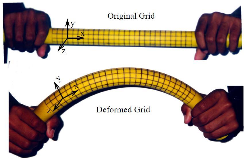
11 Symmetric ending eam: one type of prismatic bars which takes bending as the main form of deformation. Symmetric longitudinal plane: formed by the centroidal axes of cross sections. Symmetric bending: all external forces & moments acting in the symmetric longitudinal plane (beam axis being bent from a straight line to a curve within the symmetric longitudinal plane). 11

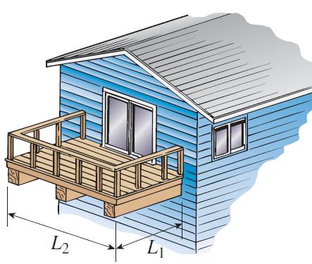
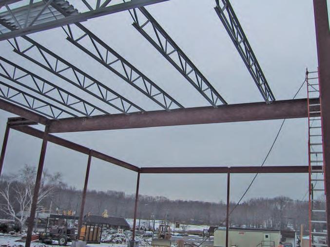
12 Types of eams Simply supported beam Cantilever beam eam with an overhang Compound beam


13 Types of Supports and Reactions ixed support Hinged or pinned support Roller support M R Rx Rx Ry Ry Ry 13
14 Internal Releases xial release Shear release Moment release 14

15 Internal Releases


16 Determinacy of eams Statically determinate beams Statically indeterminate beams - Cantilever beam - Simply supported cantilever beam - Simply supported beam - Continuous beam - Overhanging beam - ixed beam 16
17 Sign Convention of Shearing orces and ending Moments Shearing forces - Positive: left up / right down (clockwise loop) S S S S ending moment - Positive: upper half under compression / lower half under tension (top concave / bottom convex) M M M M 17
18 Sample Problem ind the shearing force and bending moment at the left and right cross-section at point C. Solution: C a a 1. Reaction forces at the supports. Internal forces (assuming positive) at the right crosssection of C. S C M a C a SC M C 18
19 3. Internal forces (assuming positive) at the left crosssection of C. SC a MC a a M C C SC a Note: for a concentrated force acting at C, the change of bending moment is zero while that of shearing force is equal to the magnitude of the concentrated force. 19
20 Sample Problem ind the shearing force and bending moment at the left and right cross-section at point C. a C Solution: a a 1. Reaction forces at the supports. Internal force at the right cross-section of C. S C M a C a SC M C 0
21 3. Internal force at the left cross-section of C. C a SC a SC a M a C a M C Note: or a concentrated moment acting at C, the change of shearing force is zero while that of bending moment is equal to the magnitude of the concentrated moment. 1
22 Direct Calculation of Shearing orces The shearing forces at a beam cross-section is equal to the net of the external forces collected from either side of the cross-section. Upward net from left portion or downward net from right portion results in positive shearing force at the cross-section. ll forces acting on a beam, including the reaction forces at the supports, must be taken into consideration.
23 Sample Problem Directly calculate the shearing force at cross-section C without the explicit use of method of section q C Solution: SC ased on the left portion from cross-section C: - ased on the right portion from cross-section C: ql SC 4 Note: in practice, we pick the portion with simpler loadings. 3
24 Direct Calculation of ending Moments The bending moment at a beam cross-section is equal to the net of the external moments with respect to the cross-section centroid, collected from either side of the cross-section Clockwise net from left portion or counter clockwise net from right portion results in positive bending moment. ll forces acting on a beam, including the reaction forces at the supports, must be taken into consideration. 4
25 Sample Problem Directly calculate the bending moment at cross-section C without the explicit use of method of section. Solution: - ased on the left portion from cross-section C M C d d 1 1 M1 1 M 1 C - ased on the right portion from cross-section C M C d d 5
26 Diagram of Shearing orces & ending Moments Equation of shearing forces and bending moments - Equation of shearing forces: S = S (x) - Equation of bending moments: M = M(x) - x: denotes the position of cross-section. Diagram of shearing forces and bending moments - bscissa: cross-section position (x) - Ordinate: shearing forces ( S ) / bending moments (M) 6
27 Sample Problem Draw the diagram of shearing forces and bending moments x 1 x C Solution: 1. Reaction force at the supports:. Equation of internal forces S( x1) S( x) a a x1 [0, a) x [0, a) Positive: left & upward Negative: right & upward 7
28 S 0.5 x1 M( x ) x1 [0, a) 1 x1 Positive: left & clockwise 0.5 x x 1 C x M( x) x x [0, a) Positive: right & counter clockwise a a M 0.5 a 8
29 Sample Problem Draw the diagram of shearing forces and bending moments x 1 a x C Solution: a a 1. Reaction forces at the supports S 0.5. Equations of internal forces S ( x1 ) ; S ( x) x x M ( x1) ; M ( x) 1 M -0.5a 0.5a 9
30 Sample Problem ql S ql x / q l ql ql / Plot the diagram of shearing forces and bending moments Solution: 1. Reaction forces at the supports. Equation of internal forces ( ) ql S x qx ql x M ( x) x qx q l ql x 8 M ql /8 0 xl 3. Diagram of internal forces 30
31 Relations among Loads, Shearing orces and ending Moments q( x) q( x) M (x) M( x) dm( x) x dx x q x dx x d x 0 S S S ( x) ( ) d ( ) S S x S x 1 M x dm x qxd x M x S xdx 0 31
32 Relations among Loads, Shearing orces and ending Moments x q x dx x d x 0 S S S x d S x q x, S S1 q x dx dx x1 1 M x dm x qxd x M x S xdx 0 x dm x x, M M xdx S 1 S dx x1 q x dm dx x Sign convention of q(x): up positive / down negative. 3
33 Relations among Loads, Shearing orces and ending Moments Without distributed load: q(x) = 0 q x d x S 0 x const dx Note: the slope of the diagram of shearing forces is zero. S dm x dx S x const M x const x const Note: the slope of the diagram of bending moments is constant. 33
34 Relations among Loads, Shearing orces and ending Moments With uniformly distributed load: q(x) = const q x d S x const const const S x x dx Note: the slope of the diagram of shearing forces is constant. dm x dx S x M x const x const x const Note: M(x) is a second order polynomial of x. 34
35 Relations among Loads, Shearing orces and ending Moments Loads Diagram of shearing forces Diagram of bending moments No load (P=0 & q=0) S 0 S S S Uniformly distributed q=const q 0 q 0 0 q q 0 Concentrated load (P) C Concentrated moment (m) C Discontinuous s Const C C Continuous but not differentiable M Discontinuous M C 35
36 Sample Problem Draw the diagram of shearing forces and bending moments. Solution: ql 8 5ql 8 S l ql / l ql /8 ql /8 C q M 36
37 Sample Problem Draw the diagram of shearing forces and bending moments. Solution: 3ql 8 ql 8 S 3ql 8 l x q 3l 8 x l l ql 8 M 9ql 18 ql 16 37
38 Sample Problem Draw the diagram of shearing forces and bending moments. Solution: qa qa qa S q qa qa / a a a qa qa / M qa / 38
39 Sample Problem Draw the diagram of shearing forces and bending moments. Solution: qa / q a q a qa qa S qa qa / qa / M qa / qa /8 39
40 Diagram of Internal orces for Plane rames Plane frames are composed of prismatic bars with different orientations in the same plane. Rigid joint ar Neighboring bars are connected via rigid joints ar Internal forces acting on cross-sections of component bars include axial force, shearing force, and bending moment. 40
41 Diagram of Internal orces for Plane rames Sign convention - xial forces: tension positive / compression negative - Shearing forces and bending moments: the same sign convention when the plane frame is observed from inside. Drawing convention - xial forces and shearing forces: draw at either side of the bar with sign labeled. - ending moments: draw at the side under tension without sign labeled. 41
42 q = 1 kn/m 4 m 3 m Sample Problem Draw the diagram of axial forces, shearing forces and bending moments for the plane frame shown below. Solution: 1. reaction forces at the supports. M / kn x kn x x y 0 y kn y D y 8 kn 1 m m E x C 1 kn 4
43 q = 1 kn/m 4 m 3 m. Diagram of internal forces 1) Diagram of axial forces C : N1 5kN DC : N 1kN D : 3kN N3 D E 5 kn C 1 kn D 8 kn 1 m m E 3 kn C 1 kn 5 kn 3 kn 3 kn 43
44 q =1 kn/m 4 m 3 m ) Diagram of shearing forces C:horizontal line DC:horizontal line D:oblique straight line D 8 kn 1 m m E C D 1kN E 3 kn C 1 kn 5 kn 1 kn 3 kn 3 kn 5 kn 3 kn 44
45 3 m q = 1 kn/m 4 m 3 m 3) Diagram of bending moments 8 kn C: oblique straight line (two-point) CD: oblique straight line (two-point) D 1 m m E C D: parabola (three-point) 3 knm D 4 knm C E 3 knm 1 kn 4 knm 4.5 knm 7 knm 3 kn 5 kn 0 3 kn 0 45
46 Diagram of Internal orces for Curved eams Draw the diagram of axial forces, shearing forces and bending moments for the curved beam shown below. Solution: Static equilibrium N sin cos M y Rsin S 46
47 Contents Introduction( 弯曲变形简介 ) The orms of Internal orces in eams( 梁中内力的形式 ) Symmetric ending( 对称弯曲 ) Types of eams( 静定梁的分类 ) Types of Supports and Reactions( 梁的支撑种类及相应的支座反力形式 ) Internal Releases( 内力释放器 ) Determinacy of eams( 梁的静定性 ) Sign Convention of Shearing orces and ending Moments( 剪力和弯矩的符号规则 ) Direct Calculation of Shearing orces( 剪力简易计算法 ) 47
48 Contents Direct Calculation of ending Moments( 弯矩简易计算法 ) Diagram of Shearing orces & ending Moments( 剪力图与弯矩图 ) Differential Relations among Loads, Shearing orces and ending Moments( 弯矩 剪力和荷载之间的微分关系 ) Diagram of Internal orces for Plane rames( 平面刚架的内力图 ) Diagram of Internal orces for Curved eams( 曲梁的内力图 ) 48
Bending Deflection.
 ending Deflection mi@seu.edu.cn ontents The Elastic urve, Deflection & Slope ( 挠曲线 挠度和转角 ) Differential Euation of the Elastic urve( 挠曲线微分方程 ) Deflection & Slope by Integration( 积分法求挠度和转角 ) oundary onditions(
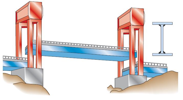
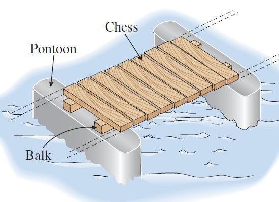
Beams. Beams are structural members that offer resistance to bending due to applied load
 Beams Beams are structural members that offer resistance to bending due to applied load 1 Beams Long prismatic members Non-prismatic sections also possible Each cross-section dimension Length of member
Chapter 4.1: Shear and Moment Diagram
 Chapter 4.1: Shear and Moment Diagram Chapter 5: Stresses in Beams Chapter 6: Classical Methods Beam Types Generally, beams are classified according to how the beam is supported and according to crosssection
Torsion.
 Torsion mi@seu.edu.cn Contents Introduction to Torsion( 扭转简介 ) Examples of Torsion Shafts( 扭转轴示例 ) Sign Convention of Torque( 扭矩符号规则 ) Torque Diagram( 扭矩图 ) Power & Torque( 功率与扭矩 ) Internal Torque & Stress
Lecture English Term Definition Chinese: Public
 Lecture English Term Definition Chinese: Public A Convert Change between two forms of measurements 变换 A Equilateral Triangle Triangle with equal sides and angles A FPS Units The American system of measurement.
Shear Force V: Positive shear tends to rotate the segment clockwise.
 INTERNL FORCES IN EM efore a structural element can be designed, it is necessary to determine the internal forces that act within the element. The internal forces for a beam section will consist of a shear
Chapter 7: Internal Forces
 Chapter 7: Internal Forces Chapter Objectives To show how to use the method of sections for determining the internal loadings in a member. To generalize this procedure by formulating equations that can
BEAM A horizontal or inclined structural member that is designed to resist forces acting to its axis is called a beam
 BEM horizontal or inclined structural member that is designed to resist forces acting to its axis is called a beam INTERNL FORCES IN BEM Whether or not a beam will break, depend on the internal resistances
Module 3. Analysis of Statically Indeterminate Structures by the Displacement Method
 odule 3 Analysis of Statically Indeterminate Structures by the Displacement ethod Lesson 16 The Slope-Deflection ethod: rames Without Sidesway Instructional Objectives After reading this chapter the student
Determinate portal frame
 eterminate portal frame onsider the frame shown in the figure below with the aim of calculating the bending moment diagram (M), shear force diagram (SF), and axial force diagram (F). P H y R x x R y L
MECHANICS OF MATERIALS. Analysis of Beams for Bending
 MECHANICS OF MATERIALS Analysis of Beams for Bending By NUR FARHAYU ARIFFIN Faculty of Civil Engineering & Earth Resources Chapter Description Expected Outcomes Define the elastic deformation of an axially
Equivalent Systems of Forces
 Equivalent Systems of orces Contents Introduction( 绪论 ) Vector Products of Two Vectors( 矢量积 ) Moment of a orce About a Point( 力对点的矩 ) Moment of a orce About a Given Axis( 力对轴的矩 ) Moment of a Couple( 力偶矩
[8] Bending and Shear Loading of Beams
![[8] Bending and Shear Loading of Beams](/thumbs/92/110949676.jpg "[8] Bending and Shear Loading of Beams") [8] Bending and Shear Loading of Beams Page 1 of 28 [8] Bending and Shear Loading of Beams [8.1] Bending of Beams (will not be covered in class) [8.2] Bending Strain and Stress [8.3] Shear in Straight
[8] Bending and Shear Loading of Beams Page 1 of 28 [8] Bending and Shear Loading of Beams [8.1] Bending of Beams (will not be covered in class) [8.2] Bending Strain and Stress [8.3] Shear in Straight
Internal Internal Forces Forces
 Internal Forces ENGR 221 March 19, 2003 Lecture Goals Internal Force in Structures Shear Forces Bending Moment Shear and Bending moment Diagrams Internal Forces and Bending The bending moment, M. Moment
SAB2223 Mechanics of Materials and Structures
 S2223 Mechanics of Materials and Structures TOPIC 2 SHER FORCE ND ENDING MOMENT Lecturer: Dr. Shek Poi Ngian TOPIC 2 SHER FORCE ND ENDING MOMENT Shear Force and ending Moment Introduction Types of beams
Engineering Mechanics Department of Mechanical Engineering Dr. G. Saravana Kumar Indian Institute of Technology, Guwahati
 Engineering Mechanics Department of Mechanical Engineering Dr. G. Saravana Kumar Indian Institute of Technology, Guwahati Module 3 Lecture 6 Internal Forces Today, we will see analysis of structures part
Chapter 7: Bending and Shear in Simple Beams
 Chapter 7: Bending and Shear in Simple Beams Introduction A beam is a long, slender structural member that resists loads that are generally applied transverse (perpendicular) to its longitudinal axis.
Purpose of this Guide: To thoroughly prepare students for the exact types of problems that will be on Exam 3.
 ES230 STRENGTH OF MTERILS Exam 3 Study Guide Exam 3: Wednesday, March 8 th in-class Updated 3/3/17 Purpose of this Guide: To thoroughly prepare students for the exact types of problems that will be on
Column Buckling.
 Column Buckling mi@seu.edu.cn Contents Stability and Buckling( 稳定性与失稳 ) Examples of Columns( 压杆应用示例 ) Conventional Design of Columns( 压杆的常规设计方法 ) Euler s Formula for in-ended Columns( 端部铰接压杆欧拉公式 ) Buckling
Pin-Jointed Frame Structures (Frameworks)
") Pin-Jointed rame Structures (rameworks) 1 Pin Jointed rame Structures (rameworks) A pin-jointed frame is a structure constructed from a number of straight members connected together at their ends by frictionless
Pin-Jointed rame Structures (rameworks) 1 Pin Jointed rame Structures (rameworks) A pin-jointed frame is a structure constructed from a number of straight members connected together at their ends by frictionless
Chapter 11. Displacement Method of Analysis Slope Deflection Method
 Chapter 11 Displacement ethod of Analysis Slope Deflection ethod Displacement ethod of Analysis Two main methods of analyzing indeterminate structure Force method The method of consistent deformations
LECTURE 14 Strength of a Bar in Transverse Bending. 1 Introduction. As we have seen, only normal stresses occur at cross sections of a rod in pure
 V. DEMENKO MECHNCS OF MTERLS 015 1 LECTURE 14 Strength of a Bar in Transverse Bending 1 ntroduction s we have seen, onl normal stresses occur at cross sections of a rod in pure bending. The corresponding
CH. 4 BEAMS & COLUMNS
 CH. 4 BEAMS & COLUMNS BEAMS Beams Basic theory of bending: internal resisting moment at any point in a beam must equal the bending moments produced by the external loads on the beam Rx = Cc + Tt - If the
Deflection of Flexural Members - Macaulay s Method 3rd Year Structural Engineering
 Deflection of Flexural Members - Macaulay s Method 3rd Year Structural Engineering 008/9 Dr. Colin Caprani 1 Contents 1. Introduction... 3 1.1 General... 3 1. Background... 4 1.3 Discontinuity Functions...
Deflection of Flexural Members - Macaulay s Method 3rd Year Structural Engineering
 Deflection of Flexural Members - Macaulay s Method 3rd Year Structural Engineering 009/10 Dr. Colin Caprani 1 Contents 1. Introduction... 4 1.1 General... 4 1. Background... 5 1.3 Discontinuity Functions...
Chapter 7 FORCES IN BEAMS AND CABLES
 hapter 7 FORES IN BEAMS AN ABLES onsider a straight two-force member AB subjected at A and B to equal and opposite forces F and -F directed along AB. utting the member AB at and drawing the free-body B
MECE 3321: Mechanics of Solids Chapter 6
 MECE 3321: Mechanics of Solids Chapter 6 Samantha Ramirez Beams Beams are long straight members that carry loads perpendicular to their longitudinal axis Beams are classified by the way they are supported
Structural Analysis III The Moment Area Method Mohr s Theorems
 Structural Analysis III The Moment Area Method Mohr s Theorems 009/10 Dr. Colin Caprani 1 Contents 1. Introduction... 4 1.1 Purpose... 4. Theory... 6.1 asis... 6. Mohr s First Theorem (Mohr I)... 8.3 Mohr
Beams are bars of material that support. Beams are common structural members. Beams can support both concentrated and distributed loads
 Outline: Review External Effects on Beams Beams Internal Effects Sign Convention Shear Force and Bending Moment Diagrams (text method) Relationships between Loading, Shear Force and Bending Moments (faster
Unit II Shear and Bending in Beams
 Unit II Shear and Bending in Beams Syllabus: Beams and Bending- Types of loads, supports - Shear Force and Bending Moment Diagrams for statically determinate beam with concentrated load, UDL, uniformly
OUT ON A LIMB AND HUNG OUT TO DRY :
 27-Nov-12 17:03 1 of 2 h p://edugen.wileyplus.com/edugen/courses/crs1404/pc/c10/c2hlchbhcmq3mjewyzewxzeuegzvcm0.enc?course=crs1404&id=ref CHAPTER 10 OUT ON A LIMB AND HUNG OUT TO DRY : A LOOK AT INTERNAL
PURE BENDING. If a simply supported beam carries two point loads of 10 kn as shown in the following figure, pure bending occurs at segment BC.
 BENDING STRESS The effect of a bending moment applied to a cross-section of a beam is to induce a state of stress across that section. These stresses are known as bending stresses and they act normally
Mechanics in Energy Resources Engineering - Chapter 5 Stresses in Beams (Basic topics)
") Week 7, 14 March Mechanics in Energy Resources Engineering - Chapter 5 Stresses in Beams (Basic topics) Ki-Bok Min, PhD Assistant Professor Energy Resources Engineering i Seoul National University Shear
Week 7, 14 March Mechanics in Energy Resources Engineering - Chapter 5 Stresses in Beams (Basic topics) Ki-Bok Min, PhD Assistant Professor Energy Resources Engineering i Seoul National University Shear
STATICALLY INDETERMINATE STRUCTURES
 STATICALLY INDETERMINATE STRUCTURES INTRODUCTION Generally the trusses are supported on (i) a hinged support and (ii) a roller support. The reaction components of a hinged support are two (in horizontal
8-5 Conjugate-Beam method. 8-5 Conjugate-Beam method. 8-5 Conjugate-Beam method. 8-5 Conjugate-Beam method
 The basis for the method comes from the similarity of eqn.1 &. to eqn 8. & 8. To show this similarity, we can write these eqn as shown dv dx w d θ M dx d M w dx d v M dx Here the shear V compares with
MECHANICS OF MATERIALS
 009 The McGraw-Hill Companies, nc. All rights reserved. Fifth S E CHAPTER 6 MECHANCS OF MATERALS Ferdinand P. Beer E. Russell Johnston, Jr. John T. DeWolf David F. Mazurek Lecture Notes: J. Walt Oler Texas
Structural Analysis III The Moment Area Method Mohr s Theorems
 Structural Analysis III The Moment Area Method Mohr s Theorems 010/11 Dr. Colin Caprani 1 Contents 1. Introduction... 4 1.1 Purpose... 4. Theory... 5.1 asis... 5. Mohr s First Theorem (Mohr I)... 7.3 Mohr
Module 4 : Deflection of Structures Lecture 4 : Strain Energy Method
 Module 4 : Deflection of Structures Lecture 4 : Strain Energy Method Objectives In this course you will learn the following Deflection by strain energy method. Evaluation of strain energy in member under
TYPES OF STRUCUTRES. HD in Civil Engineering Page 1-1
 E2027 Structural nalysis I TYPES OF STRUUTRES H in ivil Engineering Page 1-1 E2027 Structural nalysis I SUPPORTS Pin or Hinge Support pin or hinge support is represented by the symbol H or H V V Prevented:
6. Bending CHAPTER OBJECTIVES
 CHAPTER OBJECTIVES Determine stress in members caused by bending Discuss how to establish shear and moment diagrams for a beam or shaft Determine largest shear and moment in a member, and specify where
7 STATICALLY DETERMINATE PLANE TRUSSES
 7 STATICALLY DETERMINATE PLANE TRUSSES OBJECTIVES: This chapter starts with the definition of a truss and briefly explains various types of plane truss. The determinancy and stability of a truss also will
Module 2. Analysis of Statically Indeterminate Structures by the Matrix Force Method
 Module 2 Analysis of Statically Indeterminate Structures by the Matrix Force Method Lesson 11 The Force Method of Analysis: Frames Instructional Objectives After reading this chapter the student will be
SLOPE-DEFLECTION METHOD
 SLOPE-DEFLECTION ETHOD The slope-deflection method uses displacements as unknowns and is referred to as a displacement method. In the slope-deflection method, the moments at the ends of the members are
Supplement: Statically Indeterminate Trusses and Frames
 : Statically Indeterminate Trusses and Frames Approximate Analysis - In this supplement, we consider an approximate method of solving statically indeterminate trusses and frames subjected to lateral loads
Theory of structure I 2006/2013. Chapter one DETERMINACY & INDETERMINACY OF STRUCTURES
 Chapter one DETERMINACY & INDETERMINACY OF STRUCTURES Introduction A structure refers to a system of connected parts used to support a load. Important examples related to civil engineering include buildings,
7.4 The Elementary Beam Theory
 7.4 The Elementary Beam Theory In this section, problems involving long and slender beams are addressed. s with pressure vessels, the geometry of the beam, and the specific type of loading which will be
CHAPTER -6- BENDING Part -1-
 Ishik University / Sulaimani Civil Engineering Department Mechanics of Materials CE 211 CHAPTER -6- BENDING Part -1-1 CHAPTER -6- Bending Outlines of this chapter: 6.1. Chapter Objectives 6.2. Shear and
Chapter Objectives. Copyright 2011 Pearson Education South Asia Pte Ltd
 Chapter Objectives To generalize the procedure by formulating equations that can be plotted so that they describe the internal shear and moment throughout a member. To use the relations between distributed
8.3 Shear and Bending-Moment Diagrams Constructed by Areas
 8.3 Shear and ending-moment Diagrams Constructed by reas 8.3 Shear and ending-moment Diagrams Constructed by reas Procedures and Strategies, page 1 of 3 Procedures and Strategies for Solving Problems Involving
Shear Force and Bending Moment Diagrams
 Shear Force and Bending Moment Diagrams V [ N ] x[m] M [ Nm] x[m] Competencies 1. Draw shear force and bending moment diagrams for point loads and distributed loads 2. Recognize the position of maximum
Module 2. Analysis of Statically Indeterminate Structures by the Matrix Force Method
 Module 2 Analysis of Statically Indeterminate Structures by the Matrix Force Method Lesson 8 The Force Method of Analysis: Beams Instructional Objectives After reading this chapter the student will be
Types of Structures & Loads
 Structure Analysis I Chapter 4 1 Types of Structures & Loads 1Chapter Chapter 4 Internal lloading Developed in Structural Members Internal loading at a specified Point In General The loading for coplanar
UNIT IV FLEXIBILTY AND STIFFNESS METHOD
 SIDDHARTH GROUP OF INSTITUTIONS :: PUTTUR Siddharth Nagar, Narayanavanam Road 517583 QUESTION BANK (DESCRIPTIVE) Subject with Code : SA-II (13A01505) Year & Sem: III-B.Tech & I-Sem Course & Branch: B.Tech
dv dx Slope of the shear diagram = - Value of applied loading dm dx Slope of the moment curve = Shear Force
 Beams SFD and BMD Shear and Moment Relationships w dv dx Slope of the shear diagram = - Value of applied loading V dm dx Slope of the moment curve = Shear Force Both equations not applicable at the point
Module 3. Analysis of Statically Indeterminate Structures by the Displacement Method
 odule 3 Analysis of Statically Indeterminate Structures by the Displacement ethod Lesson 21 The oment- Distribution ethod: rames with Sidesway Instructional Objectives After reading this chapter the student
If the number of unknown reaction components are equal to the number of equations, the structure is known as statically determinate.
 1 of 6 EQUILIBRIUM OF A RIGID BODY AND ANALYSIS OF ETRUCTURAS II 9.1 reactions in supports and joints of a two-dimensional structure and statically indeterminate reactions: Statically indeterminate structures
Module 6. Approximate Methods for Indeterminate Structural Analysis. Version 2 CE IIT, Kharagpur
 Module 6 Approximate Methods for Indeterminate Structural Analysis Lesson 35 Indeterminate Trusses and Industrial rames Instructional Objectives: After reading this chapter the student will be able to
UNIT I ENERGY PRINCIPLES
 UNIT I ENERGY PRINCIPLES Strain energy and strain energy density- strain energy in traction, shear in flexure and torsion- Castigliano s theorem Principle of virtual work application of energy theorems
Plane Trusses Trusses
 TRUSSES Plane Trusses Trusses- It is a system of uniform bars or members (of various circular section, angle section, channel section etc.) joined together at their ends by riveting or welding and constructed
Free Body Diagram: Solution: The maximum load which can be safely supported by EACH of the support members is: ANS: A =0.217 in 2
 Problem 10.9 The angle β of the system in Problem 10.8 is 60. The bars are made of a material that will safely support a tensile normal stress of 8 ksi. Based on this criterion, if you want to design the
MECHANICS OF MATERIALS
 2009 The McGraw-Hill Companies, Inc. All rights reserved. Fifth SI Edition CHAPTER 6 MECHANICS OF MATERIALS Ferdinand P. Beer E. Russell Johnston, Jr. John T. DeWolf David F. Mazurek Lecture Notes: J.
CHAPTER 8 BENDING MOMENT AND SHEAR FORCE DIAGRAMS
 CHPTE 8 BENDING MOMENT ND SHE FOCE DIGMS EXECISE 5, Page. Determine expressions for the bending moment and shearing force distributions for the following simply supported beam; hence, or otherwise, plot
Equilibrium of a Particle
 ME 108 - Statics Equilibrium of a Particle Chapter 3 Applications For a spool of given weight, what are the forces in cables AB and AC? Applications For a given weight of the lights, what are the forces
Continuing Education Course #207 What Every Engineer Should Know About Structures Part B Statics Applications
 1 of 6 Continuing Education Course #207 What Every Engineer Should Know About Structures Part B Statics Applications 1. As a practical matter, determining design loads on structural members involves several
Calculating Truss Forces. Method of Joints
 Calculating Truss Forces Method of Joints Forces Compression body being squeezed Tension body being stretched Truss truss is composed of slender members joined together at their end points. They are usually
and F NAME: ME rd Sample Final Exam PROBLEM 1 (25 points) Prob. 1 questions are all or nothing. PROBLEM 1A. (5 points)
 Prob. 1 questions are all or nothing. PROBLEM 1A. (5 points)") ME 270 3 rd Sample inal Exam PROBLEM 1 (25 points) Prob. 1 questions are all or nothing. PROBLEM 1A. (5 points) IND: In your own words, please state Newton s Laws: 1 st Law = 2 nd Law = 3 rd Law = PROBLEM
ME 270 3 rd Sample inal Exam PROBLEM 1 (25 points) Prob. 1 questions are all or nothing. PROBLEM 1A. (5 points) IND: In your own words, please state Newton s Laws: 1 st Law = 2 nd Law = 3 rd Law = PROBLEM
Final Examination Study Set 1. (Solutions will be in the Solutions Manual of Textbook)
") Final Examination Study Set 1 (Solutions will be in the Solutions Manual of Textbook) Final Examination Study Set 2 (Solutions will be in the Solutions Manual of Textbook) 3/86 The shaft, lever,
Final Examination Study Set 1 (Solutions will be in the Solutions Manual of Textbook) Final Examination Study Set 2 (Solutions will be in the Solutions Manual of Textbook) 3/86 The shaft, lever,
FIXED BEAMS IN BENDING
 FIXED BEAMS IN BENDING INTRODUCTION Fixed or built-in beams are commonly used in building construction because they possess high rigidity in comparison to simply supported beams. When a simply supported
Module 3. Analysis of Statically Indeterminate Structures by the Displacement Method
 odule 3 Analysis of Statically Indeterminate Structures by the Displacement ethod Lesson 14 The Slope-Deflection ethod: An Introduction Introduction As pointed out earlier, there are two distinct methods
The bending moment diagrams for each span due to applied uniformly distributed and concentrated load are shown in Fig.12.4b.
 From inspection, it is assumed that the support moments at is zero and support moment at, 15 kn.m (negative because it causes compression at bottom at ) needs to be evaluated. pplying three- Hence, only
Chapter 2: Deflections of Structures
 Chapter 2: Deflections of Structures Fig. 4.1. (Fig. 2.1.) ASTU, Dept. of C Eng., Prepared by: Melkamu E. Page 1 (2.1) (4.1) (2.2) Fig.4.2 Fig.2.2 ASTU, Dept. of C Eng., Prepared by: Melkamu E. Page 2
Shear force and bending moment of beams 2.1 Beams 2.2 Classification of beams 1. Cantilever Beam Built-in encastre' Cantilever
 CHAPTER TWO Shear force and bending moment of beams 2.1 Beams A beam is a structural member resting on supports to carry vertical loads. Beams are generally placed horizontally; the amount and extent of
Assumptions: beam is initially straight, is elastically deformed by the loads, such that the slope and deflection of the elastic curve are
 *12.4 SLOPE & DISPLACEMENT BY THE MOMENT-AREA METHOD Assumptions: beam is initially straight, is elastically deformed by the loads, such that the slope and deflection of the elastic curve are very small,
Stress Analysis Lecture 4 ME 276 Spring Dr./ Ahmed Mohamed Nagib Elmekawy
 Stress Analysis Lecture 4 ME 76 Spring 017-018 Dr./ Ahmed Mohamed Nagib Elmekawy Shear and Moment Diagrams Beam Sign Convention The positive directions are as follows: The internal shear force causes a
QUESTION BANK ENGINEERS ACADEMY. Hinge E F A D. Theory of Structures Determinacy Indeterminacy 1
 Theory of Structures eterminacy Indeterminacy 1 QUSTION NK 1. The static indeterminacy of the structure shown below (a) (b) 6 (c) 9 (d) 12 2. etermine the degree of freedom of the following frame (a) 1
ENG202 Statics Lecture 16, Section 7.1
 ENG202 Statics Lecture 16, Section 7.1 Internal Forces Developed in Structural Members - Design of any structural member requires an investigation of the loading acting within the member in order to be
FIXED BEAMS CONTINUOUS BEAMS
 FIXED BEAMS CONTINUOUS BEAMS INTRODUCTION A beam carried over more than two supports is known as a continuous beam. Railway bridges are common examples of continuous beams. But the beams in railway bridges
 techie-touch.blogspot.com DEPARTMENT OF CIVIL ENGINEERING ANNA UNIVERSITY QUESTION BANK CE 2302 STRUCTURAL ANALYSIS-I TWO MARK QUESTIONS UNIT I DEFLECTION OF DETERMINATE STRUCTURES 1. Write any two important
REVIEW FOR EXAM II. Dr. Ibrahim A. Assakkaf SPRING 2002
 REVIEW FOR EXM II. J. Clark School of Engineering Department of Civil and Environmental Engineering b Dr. Ibrahim. ssakkaf SPRING 00 ENES 0 Mechanics of Materials Department of Civil and Environmental
UNIT-IV SLOPE DEFLECTION METHOD
 UNITIV SOPE EETION ETHO ontinuous beams and rigid frames (with and without sway) Symmetry and antisymmetry Simplification for hinged end Support displacements Introduction: This method was first proposed
UNIT II SLOPE DEFLECION AND MOMENT DISTRIBUTION METHOD
 SIDDHARTH GROUP OF INSTITUTIONS :: PUTTUR Siddharth Nagar, Narayanavanam Road 517583 QUESTION BANK (DESCRIPTIVE) Subject with Code : SA-II (13A01505) Year & Sem: III-B.Tech & I-Sem Course & Branch: B.Tech
Elastic Cylinders Subjected to End Loadings.
 Elastic Clinders Subjected to End Loadings mi@seu.edu.cn Outline Elastic Clinders with End Loading ( 端部受载柱体 ) Etension of Clinders ( 拉伸 ) Torsion of Clinders ( 扭转 ) Stress Function Formulation ( 应力函数体系
EMA 3702 Mechanics & Materials Science (Mechanics of Materials) Chapter 5 Beams for Bending
 Chapter 5 Beams for Bending") MA 3702 Mechanics & Materials Science (Mechanics of Materials) Chapter 5 Beams for Bending Introduction esign of beams for mechanical or civil/structural applications Transverse loading in most cases for
MA 3702 Mechanics & Materials Science (Mechanics of Materials) Chapter 5 Beams for Bending Introduction esign of beams for mechanical or civil/structural applications Transverse loading in most cases for
Hong Kong Institute of Vocational Education (Tsing Yi) Higher Diploma in Civil Engineering Structural Mechanics. Chapter 1 PRINCIPLES OF STATICS
 Higher Diploma in Civil Engineering Structural Mechanics. Chapter 1 PRINCIPLES OF STATICS") PRINCIPLES OF STTICS Statics is the study of how forces act and react on rigid bodies which are at rest or not in motion. This study is the basis for the engineering principles, which guide the design
PRINCIPLES OF STTICS Statics is the study of how forces act and react on rigid bodies which are at rest or not in motion. This study is the basis for the engineering principles, which guide the design
Lecture 8: Flexibility Method. Example
 ecture 8: lexibility Method Example The plane frame shown at the left has fixed supports at A and C. The frame is acted upon by the vertical load P as shown. In the analysis account for both flexural and
Three torques act on the shaft. Determine the internal torque at points A, B, C, and D.
 ... 7. Three torques act on the shaft. Determine the internal torque at points,, C, and D. Given: M 1 M M 3 300 Nm 400 Nm 00 Nm Solution: Section : x = 0; T M 1 M M 3 0 T M 1 M M 3 T 100.00 Nm Section
CHAPTER 7 DEFLECTIONS OF BEAMS
 CHPTER 7 DEFLECTIONS OF EMS OJECTIVES Determine the deflection and slope at specific points on beams and shafts, using various analytical methods including: o o o The integration method The use of discontinuity
ENGINEERING MECHANICS SOLUTIONS UNIT-I
 LONG QUESTIONS ENGINEERING MECHANICS SOLUTIONS UNIT-I 1. A roller shown in Figure 1 is mass 150 Kg. What force P is necessary to start the roller over the block A? =90+25 =115 = 90+25.377 = 115.377 = 360-(115+115.377)
Strength of Materials Prof. S.K.Bhattacharya Dept. of Civil Engineering, I.I.T., Kharagpur Lecture No.26 Stresses in Beams-I
 Strength of Materials Prof. S.K.Bhattacharya Dept. of Civil Engineering, I.I.T., Kharagpur Lecture No.26 Stresses in Beams-I Welcome to the first lesson of the 6th module which is on Stresses in Beams
EQUATIONS OF EQUILIBRIUM & TWO- AND THREE-FORCE MEMEBERS
 EQUATIONS OF EQUILIBRIUM & TWO- AND THREE-FORCE MEMEBERS Today s Objectives: Students will be able to: a) Apply equations of equilibrium to solve for unknowns, and b) Recognize two-force members. In-Class
CHAPTER 5 Statically Determinate Plane Trusses
 CHAPTER 5 Statically Determinate Plane Trusses TYPES OF ROOF TRUSS TYPES OF ROOF TRUSS ROOF TRUSS SETUP ROOF TRUSS SETUP OBJECTIVES To determine the STABILITY and DETERMINACY of plane trusses To analyse
ENGINEERING COUNCIL DIPLOMA LEVEL MECHANICS OF SOLIDS D209 TUTORIAL 3 - SHEAR FORCE AND BENDING MOMENTS IN BEAMS
 ENGINEERING COUNCIL DIPLOMA LEVEL MECHANICS OF SOLIDS D209 TUTORIAL 3 - SHEAR FORCE AND BENDING MOMENTS IN BEAMS You should judge your progress by completing the self assessment exercises. On completion
CHAPTER 5 Statically Determinate Plane Trusses TYPES OF ROOF TRUSS
 CHAPTER 5 Statically Determinate Plane Trusses TYPES OF ROOF TRUSS 1 TYPES OF ROOF TRUSS ROOF TRUSS SETUP 2 ROOF TRUSS SETUP OBJECTIVES To determine the STABILITY and DETERMINACY of plane trusses To analyse
- Beams are structural member supporting lateral loadings, i.e., these applied perpendicular to the axes.
 4. Shear and Moment functions - Beams are structural member supporting lateral loadings, i.e., these applied perpendicular to the aes. - The design of such members requires a detailed knowledge of the
Mechanics of Materials
 Mechanics of Materials 2. Introduction Dr. Rami Zakaria References: 1. Engineering Mechanics: Statics, R.C. Hibbeler, 12 th ed, Pearson 2. Mechanics of Materials: R.C. Hibbeler, 9 th ed, Pearson 3. Mechanics
STRESS STRAIN AND DEFORMATION OF SOLIDS, STATES OF STRESS
 1 UNIT I STRESS STRAIN AND DEFORMATION OF SOLIDS, STATES OF STRESS 1. Define: Stress When an external force acts on a body, it undergoes deformation. At the same time the body resists deformation. The
bending moment in the beam can be obtained by integration
 q 0 L 4 B = - v(l) = CCC ( ) 30 EI Example 9-5 an overhanging beam ABC with a concentrated load P applied at the end determine the equation of deflection curve and the deflection C at the end flexural
By Dr. Mohammed Ramidh
 Engineering Materials Design Lecture.6 the design of beams By Dr. Mohammed Ramidh 6.1 INTRODUCTION Finding the shear forces and bending moments is an essential step in the design of any beam. we usually
(Refer Slide Time: 2:43-03:02)
") Strength of Materials Prof. S. K. Bhattacharyya Department of Civil Engineering Indian Institute of Technology, Kharagpur Lecture - 34 Combined Stresses I Welcome to the first lesson of the eighth module
Strength of Materials Prof. S. K. Bhattacharyya Department of Civil Engineering Indian Institute of Technology, Kharagpur Lecture - 34 Combined Stresses I Welcome to the first lesson of the eighth module
OUTCOME 1 - TUTORIAL 3 BENDING MOMENTS. You should judge your progress by completing the self assessment exercises. CONTENTS
 Unit 2: Unit code: QCF Level: 4 Credit value: 15 Engineering Science L/601/1404 OUTCOME 1 - TUTORIAL 3 BENDING MOMENTS 1. Be able to determine the behavioural characteristics of elements of static engineering