Mechanics of Materials II. Chapter III. A review of the fundamental formulation of stress, strain, and deflection
|
|
|
- Leo Higgins
- 5 years ago
- Views:
Transcription

1 Mechanics of Materials II Chapter III A review of the fundamental formulation of stress, strain, and deflection
2 Outline Introduction Assumtions and limitations Axial loading Torsion of circular shafts Beam in bending Bending of symmetric beams in two planes Thin-walled pressure vessels Superposition Statically indeterminate problems Stress and strain transformations* Buckling instability of columns
3 Introduction The basic topics from mechanics of materials I include Direct axial load Shear load Torsion in circular shafts Transverse loading of long, straight, narrow beam The purpose of this chapter is to provide a concise review of the fundamental formulation (stress, strain, and deflection)
4 Assumptions and limitations Homogeneous, Isotropic and linear strain-stress relations Cross section are exact, and constant or gradually varying in the normal direction. The point of load or support connection are at suffer large distance for interested point The applied load/ or support connection are perfectly positioned geometrically Load are static and applied very gradually No initial stress effect or residual stresses
 freebody")
5 Axial loading Axial stresses P x A (a) elongation of the prismatic bar (b) freebody diagram
6 Axial loading Axial strains and deflection Hooke s law 1D x x E x y z E x y z P x AE P x AE
7 Important equations = d/l (Geometry of deformation) = P/A (Equilibrium Condition) = E (Material behavior) d PL/AE (Deformation) The product (AE) is called axial rigidity
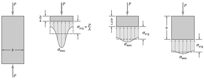
8 Saint-Venant s principle

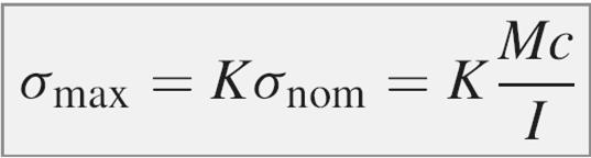
9 STRESS CONCENTRATIONS max K t nom
10 STRESS CONCENTRATION CHARTS
11


12 Stepped bar with multiple loadings

13 Flexibility versus stiffness Flexibility, f Stiffness, k
14 Non-uniform bars
15 Example 3.2-1: The limitation of homogeneous materials
16 Example 3.2-2: Deformation due to weight of the rod
17 Example 3.2-3: the displacement of two cables

18 Example of a stepped bar - Section plane at the changeof-load point - determine the internal force in each section - determine the deformation in each section
19 Example: Displacement of a three-member device Given: The rigid bar BC is supported by the 5/8 in diameter (rod AB) and ½ in (rod CD) which under load P = 12 kip at point E. Each of the rods is mad of aluminum alloy6061 with E=10x10 6 psi Find: The deflection at point E
20 Example: Displacement of a three-member device
21 Quiz: Axial loading As shown in Figure below, a rigid rod ABC is suspended by two wires. The wire AD is made of steel have cross-sectional area As = 0.14 in 2 and elastic modulus Es = 30x10 6 psi. For the aluminum-alloy wire CE, cross-section area and elastic modulus Aa =0.28 in 2 and Ea = 10x10 6 psi, respectively. Determine the displacement of point B caused by the load P = 6 kips
22 Torsion of circular shafts Assumptions The plane cross sections perpendicular to the axis of the bar remain plane after the application of a torque: points in a given plane remain in that plane after twisting. Furthermore, expansion or contraction of a cross section does not occur, nor does a shortening or lengthening of the bar. Thus all normal strains are zero. The material is homogeneous and isotropic.


23 The maximum shear strain at the outer radius c is given by: Shear strain at any arbitrary radius r is given by:

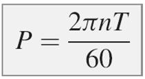
24 Torsion formula for circular shafts (C. A. Coulomb, in about 1775
25 Important equations In SI units if T is in N-m, c is in meters and J is in m 4, then t is in Pa. In English units if T is in inlb/sec, c is in inch and J is in inch 4, then t is in psi. J is called the polar moment of inertia of the entire cross section of a bar. For solid circular and hollow cross sections, J is given by the formulas (on the next slide):
26 Important formulas for J J solid = 0.5pc 4, where c is the radius of the bar In terms of the bar diameter, J = pd 4 J hollow = 0.5p(c 4 b 4 ), where c and b are the inner and outer radii of the bar In terms of the diameters, J = p(d o4 d i4 )
27 Important formulas for J For thin-walled circular members (i.e., r/t 10), an approximate formula for J is given by: J = 2pr 3 t, where r is the mean radius and t is the thickness of the tube, respectively.
28 Example3.31: A transmitted torque of step shaft

29 Example of an application

30 Coupling bolts

31 Angle of twist
32 Equation for angle of twist Geometry of deformation: g max = cf/l Equilibrium condition: t max = Tc/J Material behavior: g max = t max /G
33 Equation for angle of twist Combining the previous equations yield: f TL/GJ Torsional spring stiffness:


34 Stepped bar with multiple loads
 Ductile")
35 Torsion failures (a) Brittle material (b) Ductile material

36 Torsion tests

37 Design of circular shafts


38 In SI units: In English units:

39 Case study
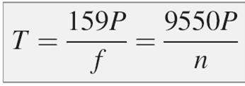
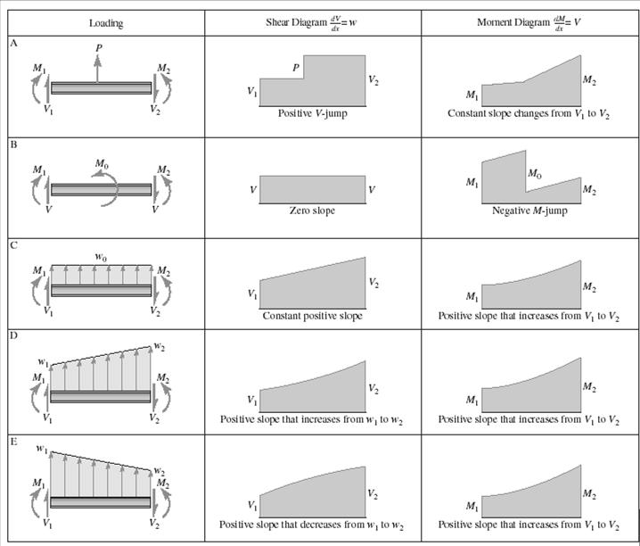
40 Beam in bending Shear Force (SF) & Bending Moment (BM) Equations and Diagram Isolation internal transverse planar surface Singularity functions Bending stresses Transverse shear stresses Bending strain and deflections Bending of symmetric beams in two planes


41 Types of beams Simple beam Cantilever beam Overhang beam
42 Sign convention In this text book.. For some other text book..
43 In this text book..

44 For some other text book..
45
46 Singularity functions Forming a single equation for describe any discontinuous functions.. F ( x) x a n n Where n is any integer For n 0 For n 0 n when x Fn ( x) x a 0 when x n n ( x a) when x a Fn ( x) x a 0 when x a a a
47
48
49 Example D.2-1: load-intensity equation q( x) R x 0 w x 0 w x a M x b P x c R x L A C D E q( x) RA x w x w x a MC x b PD x c RE x L
50 Integration rules x n a dx n 1 x a c for n 1 n 1 n 1 x a c for n 0 0 Example 2 1 x a dx x a c x a dx x a c 2
51 Example 3.4-1: SFD and BMD of Overhang beam


52 Normal stresses Distribution of bending stress in a beam. In this formula, S is called the section modulus (S = I/c)

53 Doubly symmetric cross-sectional shapes.
54 Example 3.4-2: Simply supported beam
55 Example: Single- overhang beam with distributed load and T-cross section

56 Two-plane bending problem for practice Calculate the diameter of the shaft based on maximum bending stress
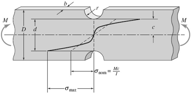
57 Stress concentration in bending
58
59

60 Transverse shear stresses
61

62 The shear formula Q is the first moment of area given by

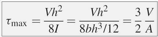
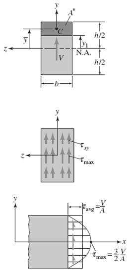
63 Shear Stress Distribution in Rectangular Beams
64 Example 3.4-3: Shear stress distribution in solid rectangular cross section beam


65 SOLID CIRCULAR SECTION BEAMS

66 HOLLOW CIRCULAR SECTION BEAMS
67 Comparison of Shear and Bending Stresses
68 If L = 10h ( long beam), then this ratio is only 1/20, which means that t max is only 5% of max
69 Bending strain and deflection x Mz y EI z My z y z EI z g xy 2(1 ) VQ y E I b z

70 Bending strain and deflection Positive loads and internal force resultants.
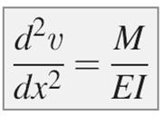
71 Bernoulli-Euler Law
72
73 Boundary conditions
74 Method of integration Find: (a) Determine the equation of the elastic curve using the double-integration approach. (b) Derive the equation of the elastic curve using the multiple-integration approach. (c) Obtain the maximum deflection and the slopes.
75 The bending moment is given by: Double integration method:

76 Integrating twice in x gives: Applying the boundary conditions we obtain: C 2 = 0 and C 1 = - w L 3 /24
77 Slope and deflection are then given by:
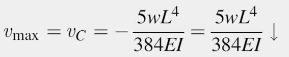
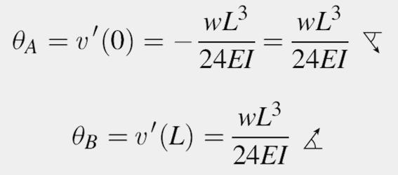
78 Largest displacements and largest slopes:
79 Example 3.4-5: Simple supports with intermediate load Find: Deflection as function of x of the centroidal axis - Discontinuous equations - singularity functions
80 Bending of symmetric beam in two planes M z y x It Mz y I z x Mz y I z M M M 2 2 z y z I I I z y z
81 Example 3.5-1: Pulley shaft system
 is equal or less than about 1/10 (or r/t 10), the vessel is")

82 Thin-walled pressure vessels If the ratio of the wall thickness (t) to the inner radius (r) is equal or less than about 1/10 (or r/t 10), the vessel is classified as thin-walled In fact, in thin-walled vessels, there is often no distinction made between the inside and outside radii because they are nearly equal.
83 Membrane equation f 2 2 F 0: 2 tr f sin 2 tr sin p r r f 0 n f f f p f r r t f
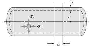
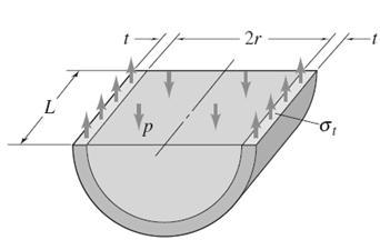
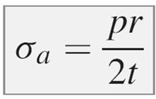
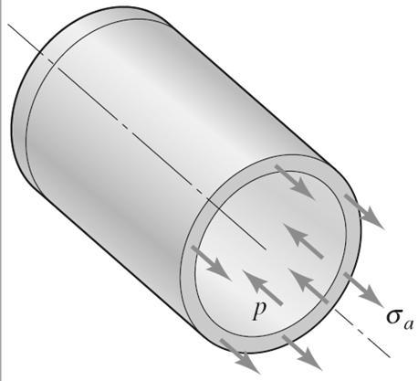
84 Cylindrical pressure vessel Tangential stress: Axial (longitudinal) stress: z


85 Spherical pressure vessels Tangential stress due to internal pressure:
86 Example : Pressure capacity of a cylindrical vessel A cylinder of thickness t = 3 mm and diameter d = 1.5 m is made of steel with yield strength 240 MPA Find: the internal pressure p that can be carried by the vessel based on a safety factor of n 2 on yielding s y 240 / n all y s MPa For circumferential p 6 t all (0.003) r kpa all For axial or longitudinal p 2 t 960 r kpa So the gage pressure may not exceed 480 kpa


87 Superposition Works well for beams with small deflections that follow linear Hooke s law For the special case when a = b = L/2:

88 Example: Slope and Deflection of a beam with an overhang
89 Example 3.7-1: Superposition
90 Example 3.7-2: Deflection equation (overhang beam)
91 Example 3.7-3: State of stress (Transverse load+torque)
92 Statically Indeterminate Problems Step 1 : Solve for all possible unknown reactions Step 2 : Subtract the number for remaining Eq n from the number of remaining unknown Ex. (n = 3-2) = 1 Step 3 : Eliminate n of unknown reactions (redundant unknown) Step 4 : Considering redundant unknown as applied force - the deflection and/or rotation at the n point Step 5 : Using the method of superposition Step 6 : Solve the simultaneous Eq n Step 7 : Substitute the results of the Step 6 into Step 1
93 Example 3.8-2: Deflection equation (overhang beam)
94
95
96
97
98
99
QUESTION BANK SEMESTER: III SUBJECT NAME: MECHANICS OF SOLIDS
 QUESTION BANK SEMESTER: III SUBJECT NAME: MECHANICS OF SOLIDS UNIT 1- STRESS AND STRAIN PART A (2 Marks) 1. Define longitudinal strain and lateral strain. 2. State Hooke s law. 3. Define modular ratio,
QUESTION BANK DEPARTMENT: CIVIL SEMESTER: III SUBJECT CODE: CE2201 SUBJECT NAME: MECHANICS OF SOLIDS UNIT 1- STRESS AND STRAIN PART A
 DEPARTMENT: CIVIL SUBJECT CODE: CE2201 QUESTION BANK SEMESTER: III SUBJECT NAME: MECHANICS OF SOLIDS UNIT 1- STRESS AND STRAIN PART A (2 Marks) 1. Define longitudinal strain and lateral strain. 2. State
COURSE TITLE : THEORY OF STRUCTURES -I COURSE CODE : 3013 COURSE CATEGORY : B PERIODS/WEEK : 6 PERIODS/SEMESTER: 90 CREDITS : 6
 COURSE TITLE : THEORY OF STRUCTURES -I COURSE CODE : 0 COURSE CATEGORY : B PERIODS/WEEK : 6 PERIODS/SEMESTER: 90 CREDITS : 6 TIME SCHEDULE Module Topics Period Moment of forces Support reactions Centre
KINGS COLLEGE OF ENGINEERING DEPARTMENT OF MECHANICAL ENGINEERING QUESTION BANK. Subject code/name: ME2254/STRENGTH OF MATERIALS Year/Sem:II / IV
 KINGS COLLEGE OF ENGINEERING DEPARTMENT OF MECHANICAL ENGINEERING QUESTION BANK Subject code/name: ME2254/STRENGTH OF MATERIALS Year/Sem:II / IV UNIT I STRESS, STRAIN DEFORMATION OF SOLIDS PART A (2 MARKS)
March 24, Chapter 4. Deflection and Stiffness. Dr. Mohammad Suliman Abuhaiba, PE
 Chapter 4 Deflection and Stiffness 1 2 Chapter Outline Spring Rates Tension, Compression, and Torsion Deflection Due to Bending Beam Deflection Methods Beam Deflections by Superposition Strain Energy Castigliano
Tuesday, February 11, Chapter 3. Load and Stress Analysis. Dr. Mohammad Suliman Abuhaiba, PE
 1 Chapter 3 Load and Stress Analysis 2 Chapter Outline Equilibrium & Free-Body Diagrams Shear Force and Bending Moments in Beams Singularity Functions Stress Cartesian Stress Components Mohr s Circle for
STRESS STRAIN AND DEFORMATION OF SOLIDS, STATES OF STRESS
 1 UNIT I STRESS STRAIN AND DEFORMATION OF SOLIDS, STATES OF STRESS 1. Define: Stress When an external force acts on a body, it undergoes deformation. At the same time the body resists deformation. The
Chapter 3. Load and Stress Analysis
 Chapter 3 Load and Stress Analysis 2 Shear Force and Bending Moments in Beams Internal shear force V & bending moment M must ensure equilibrium Fig. 3 2 Sign Conventions for Bending and Shear Fig. 3 3
Samantha Ramirez, MSE. Stress. The intensity of the internal force acting on a specific plane (area) passing through a point. F 2
 passing through a point. F 2") Samantha Ramirez, MSE Stress The intensity of the internal force acting on a specific plane (area) passing through a point. Δ ΔA Δ z Δ 1 2 ΔA Δ x Δ y ΔA is an infinitesimal size area with a uniform force
Samantha Ramirez, MSE Stress The intensity of the internal force acting on a specific plane (area) passing through a point. Δ ΔA Δ z Δ 1 2 ΔA Δ x Δ y ΔA is an infinitesimal size area with a uniform force
UNIT-I STRESS, STRAIN. 1. A Member A B C D is subjected to loading as shown in fig determine the total elongation. Take E= 2 x10 5 N/mm 2
 UNIT-I STRESS, STRAIN 1. A Member A B C D is subjected to loading as shown in fig determine the total elongation. Take E= 2 x10 5 N/mm 2 Young s modulus E= 2 x10 5 N/mm 2 Area1=900mm 2 Area2=400mm 2 Area3=625mm
UNIT 1 STRESS STRAIN AND DEFORMATION OF SOLIDS, STATES OF STRESS 1. Define stress. When an external force acts on a body, it undergoes deformation.
 UNIT 1 STRESS STRAIN AND DEFORMATION OF SOLIDS, STATES OF STRESS 1. Define stress. When an external force acts on a body, it undergoes deformation. At the same time the body resists deformation. The magnitude
Mechanical Engineering Ph.D. Preliminary Qualifying Examination Solid Mechanics February 25, 2002
 student personal identification (ID) number on each sheet. Do not write your name on any sheet. #1. A homogeneous, isotropic, linear elastic bar has rectangular cross sectional area A, modulus of elasticity
PERIYAR CENTENARY POLYTECHNIC COLLEGE PERIYAR NAGAR - VALLAM THANJAVUR. DEPARTMENT OF MECHANICAL ENGINEERING QUESTION BANK
 PERIYAR CENTENARY POLYTECHNIC COLLEGE PERIYAR NAGAR - VALLAM - 613 403 - THANJAVUR. DEPARTMENT OF MECHANICAL ENGINEERING QUESTION BANK Sub : Strength of Materials Year / Sem: II / III Sub Code : MEB 310
PES Institute of Technology
 PES Institute of Technology Bangalore south campus, Bangalore-5460100 Department of Mechanical Engineering Faculty name : Madhu M Date: 29/06/2012 SEM : 3 rd A SEC Subject : MECHANICS OF MATERIALS Subject
2. Rigid bar ABC supports a weight of W = 50 kn. Bar ABC is pinned at A and supported at B by rod (1). What is the axial force in rod (1)?
. What is the axial force in rod (1)?") IDE 110 S08 Test 1 Name: 1. Determine the internal axial forces in segments (1), (2) and (3). (a) N 1 = kn (b) N 2 = kn (c) N 3 = kn 2. Rigid bar ABC supports a weight of W = 50 kn. Bar ABC is pinned at
IDE 110 S08 Test 1 Name: 1. Determine the internal axial forces in segments (1), (2) and (3). (a) N 1 = kn (b) N 2 = kn (c) N 3 = kn 2. Rigid bar ABC supports a weight of W = 50 kn. Bar ABC is pinned at
PDDC 1 st Semester Civil Engineering Department Assignments of Mechanics of Solids [ ] Introduction, Fundamentals of Statics
![PDDC 1 st Semester Civil Engineering Department Assignments of Mechanics of Solids [ ] Introduction, Fundamentals of Statics](/thumbs/92/109382806.jpg "PDDC 1 st Semester Civil Engineering Department Assignments of Mechanics of Solids [ ] Introduction, Fundamentals of Statics") Page1 PDDC 1 st Semester Civil Engineering Department Assignments of Mechanics of Solids [2910601] Introduction, Fundamentals of Statics 1. Differentiate between Scalar and Vector quantity. Write S.I.
Page1 PDDC 1 st Semester Civil Engineering Department Assignments of Mechanics of Solids [2910601] Introduction, Fundamentals of Statics 1. Differentiate between Scalar and Vector quantity. Write S.I.
Stress Analysis Lecture 3 ME 276 Spring Dr./ Ahmed Mohamed Nagib Elmekawy
 Stress Analysis Lecture 3 ME 276 Spring 2017-2018 Dr./ Ahmed Mohamed Nagib Elmekawy Axial Stress 2 Beam under the action of two tensile forces 3 Beam under the action of two tensile forces 4 Shear Stress
ME Final Exam. PROBLEM NO. 4 Part A (2 points max.) M (x) y. z (neutral axis) beam cross-sec+on. 20 kip ft. 0.2 ft. 10 ft. 0.1 ft.
 M (x) y. z (neutral axis) beam cross-sec+on. 20 kip ft. 0.2 ft. 10 ft. 0.1 ft.") ME 323 - Final Exam Name December 15, 2015 Instructor (circle) PROEM NO. 4 Part A (2 points max.) Krousgrill 11:30AM-12:20PM Ghosh 2:30-3:20PM Gonzalez 12:30-1:20PM Zhao 4:30-5:20PM M (x) y 20 kip ft 0.2
ME 323 - Final Exam Name December 15, 2015 Instructor (circle) PROEM NO. 4 Part A (2 points max.) Krousgrill 11:30AM-12:20PM Ghosh 2:30-3:20PM Gonzalez 12:30-1:20PM Zhao 4:30-5:20PM M (x) y 20 kip ft 0.2
R13. II B. Tech I Semester Regular Examinations, Jan MECHANICS OF SOLIDS (Com. to ME, AME, AE, MTE) PART-A
 PART-A") SET - 1 II B. Tech I Semester Regular Examinations, Jan - 2015 MECHANICS OF SOLIDS (Com. to ME, AME, AE, MTE) Time: 3 hours Max. Marks: 70 Note: 1. Question Paper consists of two parts (Part-A and Part-B)
SET - 1 II B. Tech I Semester Regular Examinations, Jan - 2015 MECHANICS OF SOLIDS (Com. to ME, AME, AE, MTE) Time: 3 hours Max. Marks: 70 Note: 1. Question Paper consists of two parts (Part-A and Part-B)
NORMAL STRESS. The simplest form of stress is normal stress/direct stress, which is the stress perpendicular to the surface on which it acts.
 NORMAL STRESS The simplest form of stress is normal stress/direct stress, which is the stress perpendicular to the surface on which it acts. σ = force/area = P/A where σ = the normal stress P = the centric
Sub. Code:
 Important Instructions to examiners: ) The answers should be examined by key words and not as word-to-word as given in the model answer scheme. ) The model answer and the answer written by candidate may
MECHANICS OF MATERIALS
 STATICS AND MECHANICS OF MATERIALS Ferdinand P. Beer E. Russell Johnston, Jr, John T. DeWolf David E Mazurek \Cawect Mc / iur/» Craw SugomcT Hilt Introduction 1 1.1 What is Mechanics? 2 1.2 Fundamental
MAAE 2202 A. Come to the PASS workshop with your mock exam complete. During the workshop you can work with other students to review your work.
 It is most beneficial to you to write this mock final exam UNDER EXAM CONDITIONS. This means: Complete the exam in 3 hours. Work on your own. Keep your textbook closed. Attempt every question. After the
Consider an elastic spring as shown in the Fig.2.4. When the spring is slowly
 .3 Strain Energy Consider an elastic spring as shown in the Fig..4. When the spring is slowly pulled, it deflects by a small amount u 1. When the load is removed from the spring, it goes back to the original
EMA 3702 Mechanics & Materials Science (Mechanics of Materials) Chapter 3 Torsion
 Chapter 3 Torsion") EMA 3702 Mechanics & Materials Science (Mechanics of Materials) Chapter 3 Torsion Introduction Stress and strain in components subjected to torque T Circular Cross-section shape Material Shaft design Non-circular
EMA 3702 Mechanics & Materials Science (Mechanics of Materials) Chapter 3 Torsion Introduction Stress and strain in components subjected to torque T Circular Cross-section shape Material Shaft design Non-circular
Chapter 3. Load and Stress Analysis. Lecture Slides
 Lecture Slides Chapter 3 Load and Stress Analysis 2015 by McGraw Hill Education. This is proprietary material solely for authorized instructor use. Not authorized for sale or distribution in any manner.
Downloaded from Downloaded from / 1
 PURWANCHAL UNIVERSITY III SEMESTER FINAL EXAMINATION-2002 LEVEL : B. E. (Civil) SUBJECT: BEG256CI, Strength of Material Full Marks: 80 TIME: 03:00 hrs Pass marks: 32 Candidates are required to give their
Chapter 4-b Axially Loaded Members
 CIVL 222 STRENGTH OF MATERIALS Chapter 4-b Axially Loaded Members AXIAL LOADED MEMBERS Today s Objectives: Students will be able to: a) Determine the elastic deformation of axially loaded member b) Apply
MECHANICS OF MATERIALS
 Third E CHAPTER 2 Stress MECHANICS OF MATERIALS Ferdinand P. Beer E. Russell Johnston, Jr. John T. DeWolf Lecture Notes: J. Walt Oler Texas Tech University and Strain Axial Loading Contents Stress & Strain:
(48) CHAPTER 3: TORSION
 CHAPTER 3: TORSION") (48) CHAPTER 3: TORSION Introduction: In this chapter structural members and machine parts that are in torsion will be considered. More specifically, you will analyze the stresses and strains in members
(48) CHAPTER 3: TORSION Introduction: In this chapter structural members and machine parts that are in torsion will be considered. More specifically, you will analyze the stresses and strains in members
CE6306 STRENGTH OF MATERIALS TWO MARK QUESTIONS WITH ANSWERS ACADEMIC YEAR
 CE6306 STRENGTH OF MATERIALS TWO MARK QUESTIONS WITH ANSWERS ACADEMIC YEAR 2014-2015 UNIT - 1 STRESS, STRAIN AND DEFORMATION OF SOLIDS PART- A 1. Define tensile stress and tensile strain. The stress induced
Mechanics of Materials Primer
 Mechanics of Materials rimer Notation: A = area (net = with holes, bearing = in contact, etc...) b = total width of material at a horizontal section d = diameter of a hole D = symbol for diameter E = modulus
[8] Bending and Shear Loading of Beams
![[8] Bending and Shear Loading of Beams](/thumbs/92/110949676.jpg "[8] Bending and Shear Loading of Beams") [8] Bending and Shear Loading of Beams Page 1 of 28 [8] Bending and Shear Loading of Beams [8.1] Bending of Beams (will not be covered in class) [8.2] Bending Strain and Stress [8.3] Shear in Straight
[8] Bending and Shear Loading of Beams Page 1 of 28 [8] Bending and Shear Loading of Beams [8.1] Bending of Beams (will not be covered in class) [8.2] Bending Strain and Stress [8.3] Shear in Straight
D : SOLID MECHANICS. Q. 1 Q. 9 carry one mark each. Q.1 Find the force (in kn) in the member BH of the truss shown.
 in the member BH of the truss shown.") D : SOLID MECHANICS Q. 1 Q. 9 carry one mark each. Q.1 Find the force (in kn) in the member BH of the truss shown. Q.2 Consider the forces of magnitude F acting on the sides of the regular hexagon having
D : SOLID MECHANICS Q. 1 Q. 9 carry one mark each. Q.1 Find the force (in kn) in the member BH of the truss shown. Q.2 Consider the forces of magnitude F acting on the sides of the regular hexagon having
Lecture Slides. Chapter 4. Deflection and Stiffness. The McGraw-Hill Companies 2012
 Lecture Slides Chapter 4 Deflection and Stiffness The McGraw-Hill Companies 2012 Chapter Outline Force vs Deflection Elasticity property of a material that enables it to regain its original configuration
: APPLIED MECHANICS & STRENGTH OF MATERIALS COURSE CODE : 4021 COURSE CATEGORY : A PERIODS/ WEEK : 5 PERIODS/ SEMESTER : 75 CREDIT : 5 TIME SCHEDULE
 COURSE TITLE : APPLIED MECHANICS & STRENGTH OF MATERIALS COURSE CODE : 4021 COURSE CATEGORY : A PERIODS/ WEEK : 5 PERIODS/ SEMESTER : 75 CREDIT : 5 TIME SCHEDULE MODULE TOPIC PERIODS 1 Simple stresses
EMA 3702 Mechanics & Materials Science (Mechanics of Materials) Chapter 2 Stress & Strain - Axial Loading
 Chapter 2 Stress & Strain - Axial Loading") MA 3702 Mechanics & Materials Science (Mechanics of Materials) Chapter 2 Stress & Strain - Axial Loading MA 3702 Mechanics & Materials Science Zhe Cheng (2018) 2 Stress & Strain - Axial Loading Statics
MA 3702 Mechanics & Materials Science (Mechanics of Materials) Chapter 2 Stress & Strain - Axial Loading MA 3702 Mechanics & Materials Science Zhe Cheng (2018) 2 Stress & Strain - Axial Loading Statics
five Mechanics of Materials 1 ARCHITECTURAL STRUCTURES: FORM, BEHAVIOR, AND DESIGN DR. ANNE NICHOLS SUMMER 2017 lecture
 ARCHITECTURAL STRUCTURES: FORM, BEHAVIOR, AND DESIGN DR. ANNE NICHOLS SUMMER 2017 lecture five mechanics www.carttalk.com of materials Mechanics of Materials 1 Mechanics of Materials MECHANICS MATERIALS
STRENGTH OF MATERIALS-I. Unit-1. Simple stresses and strains
 STRENGTH OF MATERIALS-I Unit-1 Simple stresses and strains 1. What is the Principle of surveying 2. Define Magnetic, True & Arbitrary Meridians. 3. Mention different types of chains 4. Differentiate between
COURSE TITLE : APPLIED MECHANICS & STRENGTH OF MATERIALS COURSE CODE : 4017 COURSE CATEGORY : A PERIODS/WEEK : 6 PERIODS/ SEMESTER : 108 CREDITS : 5
 COURSE TITLE : APPLIED MECHANICS & STRENGTH OF MATERIALS COURSE CODE : 4017 COURSE CATEGORY : A PERIODS/WEEK : 6 PERIODS/ SEMESTER : 108 CREDITS : 5 TIME SCHEDULE MODULE TOPICS PERIODS 1 Simple stresses
Name :. Roll No. :... Invigilator s Signature :.. CS/B.TECH (CE-NEW)/SEM-3/CE-301/ SOLID MECHANICS
/SEM-3/CE-301/ SOLID MECHANICS") Name :. Roll No. :..... Invigilator s Signature :.. 2011 SOLID MECHANICS Time Allotted : 3 Hours Full Marks : 70 The figures in the margin indicate full marks. Candidates are required to give their answers
Name :. Roll No. :..... Invigilator s Signature :.. 2011 SOLID MECHANICS Time Allotted : 3 Hours Full Marks : 70 The figures in the margin indicate full marks. Candidates are required to give their answers
Chapter 4 Deflection and Stiffness
 Chapter 4 Deflection and Stiffness Asst. Prof. Dr. Supakit Rooppakhun Chapter Outline Deflection and Stiffness 4-1 Spring Rates 4-2 Tension, Compression, and Torsion 4-3 Deflection Due to Bending 4-4 Beam
Structural Analysis I Chapter 4 - Torsion TORSION
 ORSION orsional stress results from the action of torsional or twisting moments acting about the longitudinal axis of a shaft. he effect of the application of a torsional moment, combined with appropriate
D : SOLID MECHANICS. Q. 1 Q. 9 carry one mark each.
 GTE 2016 Q. 1 Q. 9 carry one mark each. D : SOLID MECHNICS Q.1 single degree of freedom vibrating system has mass of 5 kg, stiffness of 500 N/m and damping coefficient of 100 N-s/m. To make the system
SRI CHANDRASEKHARENDRA SARASWATHI VISWA MAHAVIDHYALAYA
 SRI CHANDRASEKHARENDRA SARASWATHI VISWA MAHAVIDHYALAYA (Declared as Deemed-to-be University under Section 3 of the UGC Act, 1956, Vide notification No.F.9.9/92-U-3 dated 26 th May 1993 of the Govt. of
Strength of Materials (15CV 32)
") Strength of Materials (15CV 32) Module 1 : Simple Stresses and Strains Dr. H. Ananthan, Professor, VVIET,MYSURU 8/21/2017 Introduction, Definition and concept and of stress and strain. Hooke s law, Stress-Strain
Strength of Materials (15CV 32) Module 1 : Simple Stresses and Strains Dr. H. Ananthan, Professor, VVIET,MYSURU 8/21/2017 Introduction, Definition and concept and of stress and strain. Hooke s law, Stress-Strain
The problem of transmitting a torque or rotary motion from one plane to another is frequently encountered in machine design.
 CHAPER ORSION ORSION orsion refers to the twisting of a structural member when it is loaded by moments/torques that produce rotation about the longitudinal axis of the member he problem of transmitting
[7] Torsion. [7.1] Torsion. [7.2] Statically Indeterminate Torsion. [7] Torsion Page 1 of 21
![[7] Torsion. [7.1] Torsion. [7.2] Statically Indeterminate Torsion. [7] Torsion Page 1 of 21](/thumbs/88/115835122.jpg "[7] Torsion. [7.1] Torsion. [7.2] Statically Indeterminate Torsion. [7] Torsion Page 1 of 21") [7] Torsion Page 1 of 21 [7] Torsion [7.1] Torsion [7.2] Statically Indeterminate Torsion [7] Torsion Page 2 of 21 [7.1] Torsion SHEAR STRAIN DUE TO TORSION 1) A shaft with a circular cross section is
[7] Torsion Page 1 of 21 [7] Torsion [7.1] Torsion [7.2] Statically Indeterminate Torsion [7] Torsion Page 2 of 21 [7.1] Torsion SHEAR STRAIN DUE TO TORSION 1) A shaft with a circular cross section is
Chapter 5: Torsion. 1. Torsional Deformation of a Circular Shaft 2. The Torsion Formula 3. Power Transmission 4. Angle of Twist CHAPTER OBJECTIVES
 CHAPTER OBJECTIVES Chapter 5: Torsion Discuss effects of applying torsional loading to a long straight member (shaft or tube) Determine stress distribution within the member under torsional load Determine
Torsion Stresses in Tubes and Rods
 Torsion Stresses in Tubes and Rods This initial analysis is valid only for a restricted range of problem for which the assumptions are: Rod is initially straight. Rod twists without bending. Material is
MECE 3321: Mechanics of Solids Chapter 6
 MECE 3321: Mechanics of Solids Chapter 6 Samantha Ramirez Beams Beams are long straight members that carry loads perpendicular to their longitudinal axis Beams are classified by the way they are supported
CHAPTER -6- BENDING Part -1-
 Ishik University / Sulaimani Civil Engineering Department Mechanics of Materials CE 211 CHAPTER -6- BENDING Part -1-1 CHAPTER -6- Bending Outlines of this chapter: 6.1. Chapter Objectives 6.2. Shear and
MECHANICS OF MATERIALS
 2009 The McGraw-Hill Companies, Inc. All rights reserved. Fifth SI Edition CHAPTER 3 MECHANICS OF MATERIALS Ferdinand P. Beer E. Russell Johnston, Jr. John T. DeWolf David F. Mazurek Torsion Lecture Notes:
9 MECHANICAL PROPERTIES OF SOLIDS
 9 MECHANICAL PROPERTIES OF SOLIDS Deforming force Deforming force is the force which changes the shape or size of a body. Restoring force Restoring force is the internal force developed inside the body
3 Hours/100 Marks Seat No.
 *17304* 17304 14115 3 Hours/100 Marks Seat No. Instructions : (1) All questions are compulsory. (2) Illustrate your answers with neat sketches wherever necessary. (3) Figures to the right indicate full
DEPARTMENT OF CIVIL ENGINEERING
 KINGS COLLEGE OF ENGINEERING DEPARTMENT OF CIVIL ENGINEERING SUBJECT: CE 2252 STRENGTH OF MATERIALS UNIT: I ENERGY METHODS 1. Define: Strain Energy When an elastic body is under the action of external
Only for Reference Page 1 of 18
 Only for Reference www.civilpddc2013.weebly.com Page 1 of 18 Seat No.: Enrolment No. GUJARAT TECHNOLOGICAL UNIVERSITY PDDC - SEMESTER II EXAMINATION WINTER 2013 Subject Code: X20603 Date: 26-12-2013 Subject
MECHANICS OF MATERIALS
 CHATR Stress MCHANICS OF MATRIALS and Strain Axial Loading Stress & Strain: Axial Loading Suitability of a structure or machine may depend on the deformations in the structure as well as the stresses induced
High Tech High Top Hat Technicians. An Introduction to Solid Mechanics. Is that supposed to bend there?
 High Tech High Top Hat Technicians An Introduction to Solid Mechanics Or Is that supposed to bend there? Why don't we fall through the floor? The power of any Spring is in the same proportion with the
Members Subjected to Torsional Loads
 Members Subjected to Torsional Loads Torsion of circular shafts Definition of Torsion: Consider a shaft rigidly clamped at one end and twisted at the other end by a torque T = F.d applied in a plane perpendicular
18.Define the term modulus of resilience. May/June Define Principal Stress. 20. Define Hydrostatic Pressure.
 CE6306 STREGNTH OF MATERIALS Question Bank Unit-I STRESS, STRAIN, DEFORMATION OF SOLIDS PART-A 1. Define Poison s Ratio May/June 2009 2. What is thermal stress? May/June 2009 3. Estimate the load carried
2. Determine the deflection at C of the beam given in fig below. Use principal of virtual work. W L/2 B A L C
 CE-1259, Strength of Materials UNIT I STRESS, STRAIN DEFORMATION OF SOLIDS Part -A 1. Define strain energy density. 2. State Maxwell s reciprocal theorem. 3. Define proof resilience. 4. State Castigliano
[5] Stress and Strain
![[5] Stress and Strain](/thumbs/95/123344550.jpg "[5] Stress and Strain") [5] Stress and Strain Page 1 of 34 [5] Stress and Strain [5.1] Internal Stress of Solids [5.2] Design of Simple Connections (will not be covered in class) [5.3] Deformation and Strain [5.4] Hooke s Law
[5] Stress and Strain Page 1 of 34 [5] Stress and Strain [5.1] Internal Stress of Solids [5.2] Design of Simple Connections (will not be covered in class) [5.3] Deformation and Strain [5.4] Hooke s Law
Mechanical Design in Optical Engineering. For a prismatic bar of length L in tension by axial forces P we have determined:
 Deformation of Axial Members For a prismatic bar of length L in tension by axial forces P we have determined: σ = P A δ ε = L It is important to recall that the load P must act on the centroid of the cross
Strength of Materials Prof S. K. Bhattacharya Department of Civil Engineering Indian Institute of Technology, Kharagpur Lecture - 18 Torsion - I
 Strength of Materials Prof S. K. Bhattacharya Department of Civil Engineering Indian Institute of Technology, Kharagpur Lecture - 18 Torsion - I Welcome to the first lesson of Module 4 which is on Torsion
Torsion of Shafts Learning objectives
 Torsion of Shafts Shafts are structural members with length significantly greater than the largest cross-sectional dimension used in transmitting torque from one plane to another. Learning objectives Understand
Russell C. Hibbeler. Chapter 1: Stress
 Russell C. Hibbeler Chapter 1: Stress Introduction Mechanics of materials is a study of the relationship between the external loads on a body and the intensity of the internal loads within the body. This
Mechanics of Structure
 S.Y. Diploma : Sem. III [CE/CS/CR/CV] Mechanics of Structure Time: Hrs.] Prelim Question Paper Solution [Marks : 70 Q.1(a) Attempt any SIX of the following. [1] Q.1(a) Define moment of Inertia. State MI
Comb resonator design (2)
") Lecture 6: Comb resonator design () -Intro Intro. to Mechanics of Materials School of Electrical l Engineering i and Computer Science, Seoul National University Nano/Micro Systems & Controls Laboratory
Lecture 6: Comb resonator design () -Intro Intro. to Mechanics of Materials School of Electrical l Engineering i and Computer Science, Seoul National University Nano/Micro Systems & Controls Laboratory
MECHANICS OF SOLIDS. (For B.E. Mechanical Engineering Students) As per New Revised Syllabus of APJ Abdul Kalam Technological University
 As per New Revised Syllabus of APJ Abdul Kalam Technological University") MECHANICS OF SOLIDS (For B.E. Mechanical Engineering Students) As per New Revised Syllabus of APJ Abdul Kalam Technological University Dr. S.Ramachandran, M.E., Ph.D., Mr. V.J. George, M.E., Mr. S. Kumaran,
MECHANICS OF SOLIDS (For B.E. Mechanical Engineering Students) As per New Revised Syllabus of APJ Abdul Kalam Technological University Dr. S.Ramachandran, M.E., Ph.D., Mr. V.J. George, M.E., Mr. S. Kumaran,
MECHANICS OF MATERIALS
 GE SI CHAPTER 3 MECHANICS OF MATERIALS Ferdinand P. Beer E. Russell Johnston, Jr. John T. DeWolf David F. Mazurek Torsion Lecture Notes: J. Walt Oler Texas Tech University Torsional Loads on Circular Shafts
MECHANICS OF MATERIALS
 Third CHTR Stress MCHNICS OF MTRIS Ferdinand. Beer. Russell Johnston, Jr. John T. DeWolf ecture Notes: J. Walt Oler Texas Tech University and Strain xial oading Contents Stress & Strain: xial oading Normal
MECHANICS OF MATERIALS. Prepared by Engr. John Paul Timola
 MECHANICS OF MATERIALS Prepared by Engr. John Paul Timola Mechanics of materials branch of mechanics that studies the internal effects of stress and strain in a solid body. stress is associated with the
675(1*7+ 2) 0$7(5,$/6
 0$7(5,$/6") 675(1*7+ 2) 0$7(5,$/6 (MECHANICS OF SOLIDS) (As per Leading Universities Latest syllabus including Anna University R2013 syllabus) Dr. S.Ramachandran, Professor and Research Head Faculty of Mechanical
675(1*7+ 2) 0$7(5,$/6 (MECHANICS OF SOLIDS) (As per Leading Universities Latest syllabus including Anna University R2013 syllabus) Dr. S.Ramachandran, Professor and Research Head Faculty of Mechanical
MECHANICS OF MATERIALS REVIEW
 MCHANICS OF MATRIALS RVIW Notation: - normal stress (psi or Pa) - shear stress (psi or Pa) - normal strain (in/in or m/m) - shearing strain (in/in or m/m) I - area moment of inertia (in 4 or m 4 ) J -
Chapter 5 CENTRIC TENSION OR COMPRESSION ( AXIAL LOADING )
") Chapter 5 CENTRIC TENSION OR COMPRESSION ( AXIAL LOADING ) 5.1 DEFINITION A construction member is subjected to centric (axial) tension or compression if in any cross section the single distinct stress
Chapter 5 CENTRIC TENSION OR COMPRESSION ( AXIAL LOADING ) 5.1 DEFINITION A construction member is subjected to centric (axial) tension or compression if in any cross section the single distinct stress
Aluminum shell. Brass core. 40 in
 PROBLEM #1 (22 points) A solid brass core is connected to a hollow rod made of aluminum. Both are attached at each end to a rigid plate as shown in Fig. 1. The moduli of aluminum and brass are EA=11,000
Beams. Beams are structural members that offer resistance to bending due to applied load
 Beams Beams are structural members that offer resistance to bending due to applied load 1 Beams Long prismatic members Non-prismatic sections also possible Each cross-section dimension Length of member
Module 4 : Deflection of Structures Lecture 4 : Strain Energy Method
 Module 4 : Deflection of Structures Lecture 4 : Strain Energy Method Objectives In this course you will learn the following Deflection by strain energy method. Evaluation of strain energy in member under
NAME: Given Formulae: Law of Cosines: Law of Sines:
 NME: Given Formulae: Law of Cosines: EXM 3 PST PROBLEMS (LESSONS 21 TO 28) 100 points Thursday, November 16, 2017, 7pm to 9:30, Room 200 You are allowed to use a calculator and drawing equipment, only.
MECH 401 Mechanical Design Applications
 MECH 401 Mechanical Design Applications Dr. M. O Malley Master Notes Spring 008 Dr. D. M. McStravick Rice University Updates HW 1 due Thursday (1-17-08) Last time Introduction Units Reliability engineering
Solid Mechanics Chapter 1: Tension, Compression and Shear
 Solid Mechanics Chapter 1: Tension, Compression and Shear Dr. Imran Latif Department of Civil and Environmental Engineering College of Engineering University of Nizwa (UoN) 1 Why do we study Mechanics
Chapter 5 Torsion STRUCTURAL MECHANICS: CE203. Notes are based on Mechanics of Materials: by R. C. Hibbeler, 7th Edition, Pearson
 STRUCTURAL MECHANICS: CE203 Chapter 5 Torsion Notes are based on Mechanics of Materials: by R. C. Hibbeler, 7th Edition, Pearson Dr B. Achour & Dr Eng. K. El-kashif Civil Engineering Department, University
ME 243. Mechanics of Solids
 ME 243 Mechanics of Solids Lecture 2: Stress and Strain Ahmad Shahedi Shakil Lecturer, Dept. of Mechanical Engg, BUET E-mail: sshakil@me.buet.ac.bd, shakil6791@gmail.com Website: teacher.buet.ac.bd/sshakil
Torsion of shafts with circular symmetry
 orsion of shafts with circular symmetry Introduction Consider a uniform bar which is subject to a torque, eg through the action of two forces F separated by distance d, hence Fd orsion is the resultant
MECE 3321 MECHANICS OF SOLIDS CHAPTER 1
 MECE 3321 MECHANICS O SOLIDS CHAPTER 1 Samantha Ramirez, MSE WHAT IS MECHANICS O MATERIALS? Rigid Bodies Statics Dynamics Mechanics Deformable Bodies Solids/Mech. Of Materials luids 1 WHAT IS MECHANICS
M. Vable Mechanics of Materials: Chapter 5. Torsion of Shafts
 Torsion of Shafts Shafts are structural members with length significantly greater than the largest cross-sectional dimension used in transmitting torque from one plane to another. Learning objectives Understand
Mechanical Design in Optical Engineering
 Torsion Torsion: Torsion refers to the twisting of a structural member that is loaded by couples (torque) that produce rotation about the member s longitudinal axis. In other words, the member is loaded
Chapter Objectives. Copyright 2011 Pearson Education South Asia Pte Ltd
 Chapter Objectives To determine the torsional deformation of a perfectly elastic circular shaft. To determine the support reactions when these reactions cannot be determined solely from the moment equilibrium
2012 MECHANICS OF SOLIDS
 R10 SET - 1 II B.Tech II Semester, Regular Examinations, April 2012 MECHANICS OF SOLIDS (Com. to ME, AME, MM) Time: 3 hours Max. Marks: 75 Answer any FIVE Questions All Questions carry Equal Marks ~~~~~~~~~~~~~~~~~~~~~~
6. Bending CHAPTER OBJECTIVES
 CHAPTER OBJECTIVES Determine stress in members caused by bending Discuss how to establish shear and moment diagrams for a beam or shaft Determine largest shear and moment in a member, and specify where
Mechanical Design in Optical Engineering
 OPTI Buckling Buckling and Stability: As we learned in the previous lectures, structures may fail in a variety of ways, depending on the materials, load and support conditions. We had two primary concerns:
Symmetric Bending of Beams
 Symmetric Bending of Beams beam is any long structural member on which loads act perpendicular to the longitudinal axis. Learning objectives Understand the theory, its limitations and its applications
FLEXIBILITY METHOD FOR INDETERMINATE FRAMES
 UNIT - I FLEXIBILITY METHOD FOR INDETERMINATE FRAMES 1. What is meant by indeterminate structures? Structures that do not satisfy the conditions of equilibrium are called indeterminate structure. These
4. SHAFTS. A shaft is an element used to transmit power and torque, and it can support
 4. SHAFTS A shaft is an element used to transmit power and torque, and it can support reverse bending (fatigue). Most shafts have circular cross sections, either solid or tubular. The difference between
MECHANICS OF MATERIALS
 Third CHTR Stress MCHNICS OF MTRIS Ferdinand. Beer. Russell Johnston, Jr. John T. DeWolf ecture Notes: J. Walt Oler Texas Tech University and Strain xial oading Contents Stress & Strain: xial oading Normal
3. BEAMS: STRAIN, STRESS, DEFLECTIONS
 3. BEAMS: STRAIN, STRESS, DEFLECTIONS The beam, or flexural member, is frequently encountered in structures and machines, and its elementary stress analysis constitutes one of the more interesting facets
CHAPTER THREE SYMMETRIC BENDING OF CIRCLE PLATES
 CHAPTER THREE SYMMETRIC BENDING OF CIRCLE PLATES * Governing equations in beam and plate bending ** Solution by superposition 1.1 From Beam Bending to Plate Bending 1.2 Governing Equations For Symmetric
Mechanics in Energy Resources Engineering - Chapter 5 Stresses in Beams (Basic topics)
") Week 7, 14 March Mechanics in Energy Resources Engineering - Chapter 5 Stresses in Beams (Basic topics) Ki-Bok Min, PhD Assistant Professor Energy Resources Engineering i Seoul National University Shear
Week 7, 14 March Mechanics in Energy Resources Engineering - Chapter 5 Stresses in Beams (Basic topics) Ki-Bok Min, PhD Assistant Professor Energy Resources Engineering i Seoul National University Shear
Sample Question Paper
 Scheme I Sample Question Paper Program Name : Mechanical Engineering Program Group Program Code : AE/ME/PG/PT/FG Semester : Third Course Title : Strength of Materials Marks : 70 Time: 3 Hrs. Instructions: