Chapter 4 Deflection and Stiffness
|
|
|
- Katrina Hood
- 5 years ago
- Views:
Transcription
1 Chapter 4 Deflection and Stiffness Asst. Prof. Dr. Supakit Rooppakhun
2 Chapter Outline Deflection and Stiffness 4-1 Spring Rates 4-2 Tension, Compression, and Torsion 4-3 Deflection Due to Bending 4-4 Beam Deflection Methods 4-5 Beam Deflections by Superposition 4-6 Beam Deflections by Singularity Functions 4-7 Strain Energy 4-8 Castigliano s Theorem 4-9 Deflection of Curved Members 4-10 Statically Indeterminate Problems 4-11 Compression Members General 4-12 Long Columns with Central Loading 4-13 Intermediate-Length Columns with Central Loading 4-14 Columns with Eccentric Loading 4-15 Struts or Short Compression Members 4-16 Elastic Stability 4-17 Shock and Impact
3 Spring Rates A spring is a mechanical element that exerts a force when deformed. If we designate the general relationship between force and deflection by the equation then spring rate is defined as where y must be measured in the direction of F and at the point of application of F. For linear force-deflection problems, k is a constant, also called the spring constant 3
4 Tension, Compression, and Torsion The total extension or contraction of a uniform bar in pure tension or compression, is given by The spring constant of an axially loaded bar is then The angular deflection of a uniform round bar subjected to a twisting moment T is where θ is in radians The torsional spring rate is 4
5 Deflection Due to Bending The curvature of a beam subjected to a bending moment M is given by where ρ is the radius of curvature The slope of the beam at any point x is Therefore 5
6 Example 4-1 Determine the equation for the slope and deflection of the beam, the slopes at the ends, and the max deflection. Solution wl w M x x The bending moment equation: for 0 x l 2 d y EIv EI M 2 dx 2 3 Integrating; wl w EIv Mdx x x C Integrating; wl w EIv Mdx x x C x C
7 Solution For the boundary condition, we have x 0, v 0 C 0 2 x l v C wl 3, 0 1 / 24 Therefore, wx v lx x l 24EI (2 ) w v (6lx 4 x l ) Comparing with Table A-9 24EI
8 Beam Deflection Methods There are many techniques employed to solve the integration problem for beam deflection. Some of the popular methods include : Superposition (see Sec. 4 5) The moment-area method Singularity functions (see Sec. 4 6) Numerical integration Beam Deflections by Superposition : Superposition resolves the effect of combined loading on a structure by determining the effects of each load separately and adding the results algebraically. Beam Deflections by Singularity Functions : Singularity functions are excellent for managing discontinuities, and their application to beam deflection is a simple extension. 8
9 Example 4-2 Consider the uniformly loaded beam with a concentrated force. Using superposition, determine the reaction and deflection as a function of x. Solution Using superposition method, we have
10 Solution Therefore, R1 Fb wl R2 l 2 Fa l wl 2 Fbx wx yab x b l lx x l 6EIl 24EI ( ) (2 ) Fa l x wx ybc x a lx lx x l 6EIl 24EI ( ) ( ) ( )
11 Example 4-3 Consider the beam shown in Figure. Determine the deflection equations using superposition. Solution For the segment AB, we have
12 Solution Therefore, wx Fax yab lx x l l x 24EI 6EIl (2 ) ( ) For the segment BC, the deflection is straight since there is no bending moment due to w. The slope of beam at point B is or where x =l B y B dy d wx dx dx 24EI (2 lx x l ) 3 w wl 24EI 24EI B (6ll 4 l l ) x l
13 Solution The deflection in segment BC due to w is deflection due to F in BC, yields B ( x l ) and adding this to the 3 wl F( x l) 2 ( ) ( ) (3 ) ybc x l l x a x l 24EI 6EI
14 Strain Energy The external work done on an elastic member in deforming it is transformed into strain, or potential, energy. The energy is equal to the product of the average force and the deflection, or For tension and compression The strain energy due to direct shear The strain energy for torsion is given by 14

15 Strain Energy in Beam Bending The strain energy stored in a section of the elastic curve of length ds is du = (M/2)dθ. For small deflections, ds =dx. Then, for the entire beam Summarized to include both the integral and nonintegral form, the strain energy for bending is The strain energy due to shear loading of a beam can be approximated as 15
16 Example 4-8 A cantilever beam with a round cross section has a concentrated load F at the free end, as shown in Figure. Find the strain energy in the beam Solution Consider the FBD, we have V F M Fx For the transverse shear, the correction factor C = 1.11 (circular cross section) The transverse shear strain energy is The bending strain energy is U shear 2 2 CV 1.11F l dx 2AG 2AG 2 l F l M Ubend dx ( Fx) dx 2EI 2EI 6EI 0 Therefore, the total strain energy is F l 1.11F l Utotal Ubend U shear 6EI 2AG
17 Castigliano s Theorem Castigliano s theorem states that when forces act on elastic systems subject to small displacements, the displacement corresponding to any force, in the direction of the force, is equal to the partial derivative of the total strain energy with respect to that force. Mathematically, the theorem of Castigliano is where δ is the displacement of the point of application of the force F i in the direction of F i Castigliano s theorem can be used to find the deflection at a point even though no force or moment acts there. Set up the equation for the total strain energy U Find an expression for the desired deflection δ Since Q is a fictitious force, solve the expression by setting Q equal to zero. 17
18 Example 4-9 A cantilever beam of previous example, is a carbon steel bar 250 mm long with a 25-mm diameter and is loaded by a force F = 400 N. a) Find the maximum deflection using Castigliano s theorem (including that due to shear effect) b) What error is introduced if shear is neglected? Solution From previous example, U total F l 1.11F l 6EI 2AG According to Castigliano s theorem, the deflection of the end is max F 3EI AG 3 U Fl 1.11Fl For the area properties, 4 4 d (25) I 19,175 mm d (25) A 491 mm
19 Solution Substituting these values, F 400 N, l 0.25 m, E 209 GPa, G 79 GPa max mm Note that the result is positive because it is in the same direction as the force F. b) If neglecting shear, we have max ( ) mm 0.57% 0.523
20 Example 4-10 Using Castigliano s method, determine the deflections of point A and B due to the force F applied at the end of the step shaft shown in Figure. (The second area moments for section AB and BC are I 1 and 2I 1, respectively) The deflection at A is Solution For 0 x l, the bending moment is M Fx Substituting,
21 Solution Therefore, The deflection at B is
22 Statically Indeterminate Problems A system when it is said to be statically indeterminate with more unknown support (reaction) forces and/or moments than static equilibrium equations. The extra constraint supports are called redundant supports. A deflection equation is required for each redundant support reaction in order to obtain a solution. Procedure Choose the redundant reaction(s). Write the equations of static equilibrium. Write the deflection equation(s) for the point(s) at the locations of the redundant reaction(s) in terms of the applied loads and the redundant reaction(s) The equations can now be solved to determine the reactions. 22
23 Example 4-14 Determine the reaction of the indeterminate beam 11 of Appendix A-9 Solution
24 Compression Member-General The term column is applied to all such members except those in which failure would be by simple or pure compression. Columns can be categorized then as: Long columns with central loading Intermediate-length columns with central loading Columns with eccentric loading Struts or short columns with eccentric loading
25 Long Columns with Central Loading If the axial force P shown acts along the centroidal axis of the column, simple compression of the member occurs for low values of the force. Under certain conditions, when P reaches a specific value, the column becomes unstable and bending develops rapidly. The critical force for the pin-ended column is given by which is called the Euler column formula. Euler Column formula can be extended to apply to other endconditions by writing where the constant C depends on the end conditions 25

26 Euler Column Formula : General Using the relation I = Ak 2, where A is the area and k the radius of gyration. Euler Column Equation can be rearranged as where l/k is called the slenderness ratio The quantity P cr /A is the critical unit load. It is the load per unit area necessary to place the column in a condition of unstable equilibrium. The factor C is called the end-condition constant, and it may have any one of the theoretical values 1/4, 1, 2, and 4, depending upon the manner in which the load is applied. 26
 1 Most designers select point T such that P cr /A = S y /2 with corresponding value of (l/k) 1")
27 Euler Column Formula : Application In practical engineering applications where defects such as initial crookedness or load eccentricities exit, the Euler equation can only be used for slenderness ratio greater than (l/k) 1 Most designers select point T such that P cr /A = S y /2 with corresponding value of (l/k) 1 to be 27
28 Johnson Formula for Intermediate-Length Column For the slenderness ratio that Euler column formula does not apply, the equation developed by J.B, Johnson as the parabolic or J.B, Johnson formula could be used. If the parabola is begun at S y, then a = S y. If point T is selected as previously noted, then the value of(l/k) 1 and the constant b is found to be Upon substituting the known values of a and b,we obtain the parabolic equation 28
29 Columns with Eccentric Loading Load eccentricities or crookedness are likely to occur during manufacture and assembly. A column with the line of action of the column forces separated from the centroidal axis of the column by the eccentricity e results in the differential equation The solution of Eq. (a), for the boundary conditions that y =0 at x =0, l is The maximum bending moment also occurs at midspan and is 29
30 Secant Column Formula The magnitude of the maximum compressive stress at midspan is found by superposing the axial component and the bending component. By imposing the compressive yield strength S yc as the maximum value of σ c The term ec/k 2 is called the eccentricity ratio. 30
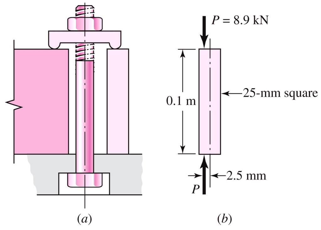
31 Solution Example 4-16 Develop specific Euler equation for the sizes of columns having a) Round cross section b) Rectangular cross section
32 Example 4-17 Solution From the round column with C = 1, we have Therefore, the preferred size is 40 mm
33 Solution

34 Example 4-19
35 Solution
36 Solution
37 Struts or Short Compression Members A strut is a short compression member such that the maximum compressive stress in the x direction at point B in an intermediate section is the sum of a simple component P/A and a flexural component Mc/I where k = (I/A) 1/2 and is the radius of gyration, c is the coordinate of point B, and e is the eccentricity of loading. How long is a short member? If we decide that the limiting percentage is to be 1 percent of e, then, from Eq. (4 44), the limiting slenderness ratio turns out to be 37

38 Example 4-20
39 Solution
40 HOMEWORK 1) Using superposition, find the deflection of the steel shaft at A in the figure. Find the deflection at midspan. By what percentage do these two values differ?
41 HOMEWORK 2) Using Castigliano s theorem, determine the maximum deflection for the uniformly loaded cantilever beam 3 (Table A-9). Neglect shear.
42 HOMEWORK 3) The figure shows a rectangular member OB, made from 6-mm-thick aluminum plate, pinned to the ground at one end and supported by a 12-mmdiameter round steel rod with hooks formed on the ends. A load of 400 N is applied as shown. Determine the vertical deflection at point B by, a) Using superposition b) Using Castigliano s theorem

43 HOMEWORK 4) For the beam shown, determine the support reaction using superposition.
44 Solution 3a)
45 Solution 3a)
46 Solution 3b)
47 Solution 3b)
48 Solution 4)
Lecture Slides. Chapter 4. Deflection and Stiffness. The McGraw-Hill Companies 2012
 Lecture Slides Chapter 4 Deflection and Stiffness The McGraw-Hill Companies 2012 Chapter Outline Force vs Deflection Elasticity property of a material that enables it to regain its original configuration
March 24, Chapter 4. Deflection and Stiffness. Dr. Mohammad Suliman Abuhaiba, PE
 Chapter 4 Deflection and Stiffness 1 2 Chapter Outline Spring Rates Tension, Compression, and Torsion Deflection Due to Bending Beam Deflection Methods Beam Deflections by Superposition Strain Energy Castigliano
Chapter 5 Elastic Strain, Deflection, and Stability 1. Elastic Stress-Strain Relationship
 Chapter 5 Elastic Strain, Deflection, and Stability Elastic Stress-Strain Relationship A stress in the x-direction causes a strain in the x-direction by σ x also causes a strain in the y-direction & z-direction
Mechanical Design in Optical Engineering
 OPTI Buckling Buckling and Stability: As we learned in the previous lectures, structures may fail in a variety of ways, depending on the materials, load and support conditions. We had two primary concerns:
CHAPTER -6- BENDING Part -1-
 Ishik University / Sulaimani Civil Engineering Department Mechanics of Materials CE 211 CHAPTER -6- BENDING Part -1-1 CHAPTER -6- Bending Outlines of this chapter: 6.1. Chapter Objectives 6.2. Shear and
Mechanics of Materials II. Chapter III. A review of the fundamental formulation of stress, strain, and deflection
 Mechanics of Materials II Chapter III A review of the fundamental formulation of stress, strain, and deflection Outline Introduction Assumtions and limitations Axial loading Torsion of circular shafts
[8] Bending and Shear Loading of Beams
![[8] Bending and Shear Loading of Beams](/thumbs/92/110949676.jpg "[8] Bending and Shear Loading of Beams") [8] Bending and Shear Loading of Beams Page 1 of 28 [8] Bending and Shear Loading of Beams [8.1] Bending of Beams (will not be covered in class) [8.2] Bending Strain and Stress [8.3] Shear in Straight
[8] Bending and Shear Loading of Beams Page 1 of 28 [8] Bending and Shear Loading of Beams [8.1] Bending of Beams (will not be covered in class) [8.2] Bending Strain and Stress [8.3] Shear in Straight
Lecture 15 Strain and stress in beams
 Spring, 2019 ME 323 Mechanics of Materials Lecture 15 Strain and stress in beams Reading assignment: 6.1 6.2 News: Instructor: Prof. Marcial Gonzalez Last modified: 1/6/19 9:42:38 PM Beam theory (@ ME
Consider an elastic spring as shown in the Fig.2.4. When the spring is slowly
 .3 Strain Energy Consider an elastic spring as shown in the Fig..4. When the spring is slowly pulled, it deflects by a small amount u 1. When the load is removed from the spring, it goes back to the original
Module 4 : Deflection of Structures Lecture 4 : Strain Energy Method
 Module 4 : Deflection of Structures Lecture 4 : Strain Energy Method Objectives In this course you will learn the following Deflection by strain energy method. Evaluation of strain energy in member under
CE6306 STRENGTH OF MATERIALS TWO MARK QUESTIONS WITH ANSWERS ACADEMIC YEAR
 CE6306 STRENGTH OF MATERIALS TWO MARK QUESTIONS WITH ANSWERS ACADEMIC YEAR 2014-2015 UNIT - 1 STRESS, STRAIN AND DEFORMATION OF SOLIDS PART- A 1. Define tensile stress and tensile strain. The stress induced
EMA 3702 Mechanics & Materials Science (Mechanics of Materials) Chapter 10 Columns
 Chapter 10 Columns") EMA 370 Mechanics & Materials Science (Mechanics of Materials) Chapter 10 Columns Columns Introduction Columns are vertical prismatic members subjected to compressive forces Goals: 1. Study the stability
EMA 370 Mechanics & Materials Science (Mechanics of Materials) Chapter 10 Columns Columns Introduction Columns are vertical prismatic members subjected to compressive forces Goals: 1. Study the stability
Assumptions: beam is initially straight, is elastically deformed by the loads, such that the slope and deflection of the elastic curve are
 *12.4 SLOPE & DISPLACEMENT BY THE MOMENT-AREA METHOD Assumptions: beam is initially straight, is elastically deformed by the loads, such that the slope and deflection of the elastic curve are very small,
2 marks Questions and Answers
 1. Define the term strain energy. A: Strain Energy of the elastic body is defined as the internal work done by the external load in deforming or straining the body. 2. Define the terms: Resilience and
3. BEAMS: STRAIN, STRESS, DEFLECTIONS
 3. BEAMS: STRAIN, STRESS, DEFLECTIONS The beam, or flexural member, is frequently encountered in structures and machines, and its elementary stress analysis constitutes one of the more interesting facets
BEAM DEFLECTION THE ELASTIC CURVE
 BEAM DEFLECTION Samantha Ramirez THE ELASTIC CURVE The deflection diagram of the longitudinal axis that passes through the centroid of each cross-sectional area of a beam. Supports that apply a moment
6. Bending CHAPTER OBJECTIVES
 CHAPTER OBJECTIVES Determine stress in members caused by bending Discuss how to establish shear and moment diagrams for a beam or shaft Determine largest shear and moment in a member, and specify where
Mechanics of Materials Primer
 Mechanics of Materials rimer Notation: A = area (net = with holes, bearing = in contact, etc...) b = total width of material at a horizontal section d = diameter of a hole D = symbol for diameter E = modulus
MECE 3321: Mechanics of Solids Chapter 6
 MECE 3321: Mechanics of Solids Chapter 6 Samantha Ramirez Beams Beams are long straight members that carry loads perpendicular to their longitudinal axis Beams are classified by the way they are supported
Review of Strain Energy Methods and Introduction to Stiffness Matrix Methods of Structural Analysis
 uke University epartment of Civil and Environmental Engineering CEE 42L. Matrix Structural Analysis Henri P. Gavin Fall, 22 Review of Strain Energy Methods and Introduction to Stiffness Matrix Methods
QUESTION BANK SEMESTER: III SUBJECT NAME: MECHANICS OF SOLIDS
 QUESTION BANK SEMESTER: III SUBJECT NAME: MECHANICS OF SOLIDS UNIT 1- STRESS AND STRAIN PART A (2 Marks) 1. Define longitudinal strain and lateral strain. 2. State Hooke s law. 3. Define modular ratio,
D : SOLID MECHANICS. Q. 1 Q. 9 carry one mark each.
 GTE 2016 Q. 1 Q. 9 carry one mark each. D : SOLID MECHNICS Q.1 single degree of freedom vibrating system has mass of 5 kg, stiffness of 500 N/m and damping coefficient of 100 N-s/m. To make the system
PES Institute of Technology
 PES Institute of Technology Bangalore south campus, Bangalore-5460100 Department of Mechanical Engineering Faculty name : Madhu M Date: 29/06/2012 SEM : 3 rd A SEC Subject : MECHANICS OF MATERIALS Subject
Structural Dynamics Lecture Eleven: Dynamic Response of MDOF Systems: (Chapter 11) By: H. Ahmadian
 By: H. Ahmadian") Structural Dynamics Lecture Eleven: Dynamic Response of MDOF Systems: (Chapter 11) By: H. Ahmadian ahmadian@iust.ac.ir Dynamic Response of MDOF Systems: Mode-Superposition Method Mode-Superposition Method:
Structural Dynamics Lecture Eleven: Dynamic Response of MDOF Systems: (Chapter 11) By: H. Ahmadian ahmadian@iust.ac.ir Dynamic Response of MDOF Systems: Mode-Superposition Method Mode-Superposition Method:
MAAE 2202 A. Come to the PASS workshop with your mock exam complete. During the workshop you can work with other students to review your work.
 It is most beneficial to you to write this mock final exam UNDER EXAM CONDITIONS. This means: Complete the exam in 3 hours. Work on your own. Keep your textbook closed. Attempt every question. After the
needed to buckle an ideal column. Analyze the buckling with bending of a column. Discuss methods used to design concentric and eccentric columns.
 CHAPTER OBJECTIVES Discuss the behavior of columns. Discuss the buckling of columns. Determine the axial load needed to buckle an ideal column. Analyze the buckling with bending of a column. Discuss methods
Comb resonator design (2)
") Lecture 6: Comb resonator design () -Intro Intro. to Mechanics of Materials School of Electrical l Engineering i and Computer Science, Seoul National University Nano/Micro Systems & Controls Laboratory
Lecture 6: Comb resonator design () -Intro Intro. to Mechanics of Materials School of Electrical l Engineering i and Computer Science, Seoul National University Nano/Micro Systems & Controls Laboratory
[7] Torsion. [7.1] Torsion. [7.2] Statically Indeterminate Torsion. [7] Torsion Page 1 of 21
![[7] Torsion. [7.1] Torsion. [7.2] Statically Indeterminate Torsion. [7] Torsion Page 1 of 21](/thumbs/88/115835122.jpg "[7] Torsion. [7.1] Torsion. [7.2] Statically Indeterminate Torsion. [7] Torsion Page 1 of 21") [7] Torsion Page 1 of 21 [7] Torsion [7.1] Torsion [7.2] Statically Indeterminate Torsion [7] Torsion Page 2 of 21 [7.1] Torsion SHEAR STRAIN DUE TO TORSION 1) A shaft with a circular cross section is
[7] Torsion Page 1 of 21 [7] Torsion [7.1] Torsion [7.2] Statically Indeterminate Torsion [7] Torsion Page 2 of 21 [7.1] Torsion SHEAR STRAIN DUE TO TORSION 1) A shaft with a circular cross section is
Chapter 12 Elastic Stability of Columns
 Chapter 12 Elastic Stability of Columns Axial compressive loads can cause a sudden lateral deflection (Buckling) For columns made of elastic-perfectly plastic materials, P cr Depends primarily on E and
MECHANICS OF MATERIALS
 STATICS AND MECHANICS OF MATERIALS Ferdinand P. Beer E. Russell Johnston, Jr, John T. DeWolf David E Mazurek \Cawect Mc / iur/» Craw SugomcT Hilt Introduction 1 1.1 What is Mechanics? 2 1.2 Fundamental
Chapter 2: Deflections of Structures
 Chapter 2: Deflections of Structures Fig. 4.1. (Fig. 2.1.) ASTU, Dept. of C Eng., Prepared by: Melkamu E. Page 1 (2.1) (4.1) (2.2) Fig.4.2 Fig.2.2 ASTU, Dept. of C Eng., Prepared by: Melkamu E. Page 2
Beams. Beams are structural members that offer resistance to bending due to applied load
 Beams Beams are structural members that offer resistance to bending due to applied load 1 Beams Long prismatic members Non-prismatic sections also possible Each cross-section dimension Length of member
Stress Analysis Lecture 4 ME 276 Spring Dr./ Ahmed Mohamed Nagib Elmekawy
 Stress Analysis Lecture 4 ME 76 Spring 017-018 Dr./ Ahmed Mohamed Nagib Elmekawy Shear and Moment Diagrams Beam Sign Convention The positive directions are as follows: The internal shear force causes a
Tuesday, February 11, Chapter 3. Load and Stress Analysis. Dr. Mohammad Suliman Abuhaiba, PE
 1 Chapter 3 Load and Stress Analysis 2 Chapter Outline Equilibrium & Free-Body Diagrams Shear Force and Bending Moments in Beams Singularity Functions Stress Cartesian Stress Components Mohr s Circle for
Chapter 3. Load and Stress Analysis. Lecture Slides
 Lecture Slides Chapter 3 Load and Stress Analysis 2015 by McGraw Hill Education. This is proprietary material solely for authorized instructor use. Not authorized for sale or distribution in any manner.
STRESS STRAIN AND DEFORMATION OF SOLIDS, STATES OF STRESS
 1 UNIT I STRESS STRAIN AND DEFORMATION OF SOLIDS, STATES OF STRESS 1. Define: Stress When an external force acts on a body, it undergoes deformation. At the same time the body resists deformation. The
Members Subjected to Torsional Loads
 Members Subjected to Torsional Loads Torsion of circular shafts Definition of Torsion: Consider a shaft rigidly clamped at one end and twisted at the other end by a torque T = F.d applied in a plane perpendicular
COURSE TITLE : APPLIED MECHANICS & STRENGTH OF MATERIALS COURSE CODE : 4017 COURSE CATEGORY : A PERIODS/WEEK : 6 PERIODS/ SEMESTER : 108 CREDITS : 5
 COURSE TITLE : APPLIED MECHANICS & STRENGTH OF MATERIALS COURSE CODE : 4017 COURSE CATEGORY : A PERIODS/WEEK : 6 PERIODS/ SEMESTER : 108 CREDITS : 5 TIME SCHEDULE MODULE TOPICS PERIODS 1 Simple stresses
MECHANICS OF MATERIALS
 CHTER MECHNICS OF MTERILS 10 Ferdinand. Beer E. Russell Johnston, Jr. Columns John T. DeWolf cture Notes: J. Walt Oler Texas Tech University 006 The McGraw-Hill Companies, Inc. ll rights reserved. Columns
: APPLIED MECHANICS & STRENGTH OF MATERIALS COURSE CODE : 4021 COURSE CATEGORY : A PERIODS/ WEEK : 5 PERIODS/ SEMESTER : 75 CREDIT : 5 TIME SCHEDULE
 COURSE TITLE : APPLIED MECHANICS & STRENGTH OF MATERIALS COURSE CODE : 4021 COURSE CATEGORY : A PERIODS/ WEEK : 5 PERIODS/ SEMESTER : 75 CREDIT : 5 TIME SCHEDULE MODULE TOPIC PERIODS 1 Simple stresses
MECH 401 Mechanical Design Applications
 MECH 40 Mechanical Design Applications Dr. M. K. O Malley Master Notes Spring 008 Dr. D. M. McStravick Rice University Design Considerations Stress Deflection Strain Stiffness Stability Often the controlling
DEPARTMENT OF CIVIL ENGINEERING
 KINGS COLLEGE OF ENGINEERING DEPARTMENT OF CIVIL ENGINEERING SUBJECT: CE 2252 STRENGTH OF MATERIALS UNIT: I ENERGY METHODS 1. Define: Strain Energy When an elastic body is under the action of external
ME 323 Examination #2 April 11, 2018
 ME 2 Eamination #2 April, 2 PROBLEM NO. 25 points ma. A thin-walled pressure vessel is fabricated b welding together two, open-ended stainless-steel vessels along a 6 weld line. The welded vessel has an
7.5 Elastic Buckling Columns and Buckling
 7.5 Elastic Buckling The initial theory of the buckling of columns was worked out by Euler in 1757, a nice example of a theory preceding the application, the application mainly being for the later invented
KINGS COLLEGE OF ENGINEERING DEPARTMENT OF MECHANICAL ENGINEERING QUESTION BANK. Subject code/name: ME2254/STRENGTH OF MATERIALS Year/Sem:II / IV
 KINGS COLLEGE OF ENGINEERING DEPARTMENT OF MECHANICAL ENGINEERING QUESTION BANK Subject code/name: ME2254/STRENGTH OF MATERIALS Year/Sem:II / IV UNIT I STRESS, STRAIN DEFORMATION OF SOLIDS PART A (2 MARKS)
Elastic Stability Of Columns
 Elastic Stability Of Columns Introduction: Structural members which carry compressive loads may be divided into two broad categories depending on their relative lengths and cross-sectional dimensions.
QUESTION BANK DEPARTMENT: CIVIL SEMESTER: III SUBJECT CODE: CE2201 SUBJECT NAME: MECHANICS OF SOLIDS UNIT 1- STRESS AND STRAIN PART A
 DEPARTMENT: CIVIL SUBJECT CODE: CE2201 QUESTION BANK SEMESTER: III SUBJECT NAME: MECHANICS OF SOLIDS UNIT 1- STRESS AND STRAIN PART A (2 Marks) 1. Define longitudinal strain and lateral strain. 2. State
Shafts: Torsion of Circular Shafts Reading: Crandall, Dahl and Lardner 6.2, 6.3
 M9 Shafts: Torsion of Circular Shafts Reading: Crandall, Dahl and Lardner 6., 6.3 A shaft is a structural member which is long and slender and subject to a torque (moment) acting about its long axis. We
Unit III Theory of columns. Dr.P.Venkateswara Rao, Associate Professor, Dept. of Civil Engg., SVCE, Sriperumbudir
 Unit III Theory of columns 1 Unit III Theory of Columns References: Punmia B.C.,"Theory of Structures" (SMTS) Vol II, Laxmi Publishing Pvt Ltd, New Delhi 2004. Rattan.S.S., "Strength of Materials", Tata
BEAM A horizontal or inclined structural member that is designed to resist forces acting to its axis is called a beam
 BEM horizontal or inclined structural member that is designed to resist forces acting to its axis is called a beam INTERNL FORCES IN BEM Whether or not a beam will break, depend on the internal resistances
FINAL EXAMINATION. (CE130-2 Mechanics of Materials)
") UNIVERSITY OF CLIFORNI, ERKELEY FLL SEMESTER 001 FINL EXMINTION (CE130- Mechanics of Materials) Problem 1: (15 points) pinned -bar structure is shown in Figure 1. There is an external force, W = 5000N,
UNIVERSITY OF CLIFORNI, ERKELEY FLL SEMESTER 001 FINL EXMINTION (CE130- Mechanics of Materials) Problem 1: (15 points) pinned -bar structure is shown in Figure 1. There is an external force, W = 5000N,
INTRODUCTION TO STRAIN
 SIMPLE STRAIN INTRODUCTION TO STRAIN In general terms, Strain is a geometric quantity that measures the deformation of a body. There are two types of strain: normal strain: characterizes dimensional changes,
7.6 Stress in symmetrical elastic beam transmitting both shear force and bending moment
 7.6 Stress in symmetrical elastic beam transmitting both shear force and bending moment à It is more difficult to obtain an exact solution to this problem since the presence of the shear force means that
Chapter 8 Structural Design and Analysis. Strength and stiffness 5 types of load: Tension Compression Shear Bending Torsion
 Chapter 8 Structural Design and Analysis 1 Strength and stiffness 5 types of load: Tension Compression Shear Bending Torsion Normal Stress Stress is a state when a material is loaded. For normal forces
ENG2000 Chapter 7 Beams. ENG2000: R.I. Hornsey Beam: 1
 ENG2000 Chapter 7 Beams ENG2000: R.I. Hornsey Beam: 1 Overview In this chapter, we consider the stresses and moments present in loaded beams shear stress and bending moment diagrams We will also look at
FIXED BEAMS IN BENDING
 FIXED BEAMS IN BENDING INTRODUCTION Fixed or built-in beams are commonly used in building construction because they possess high rigidity in comparison to simply supported beams. When a simply supported
Chapter 3. Load and Stress Analysis
 Chapter 3 Load and Stress Analysis 2 Shear Force and Bending Moments in Beams Internal shear force V & bending moment M must ensure equilibrium Fig. 3 2 Sign Conventions for Bending and Shear Fig. 3 3
CHAPTER THREE SYMMETRIC BENDING OF CIRCLE PLATES
 CHAPTER THREE SYMMETRIC BENDING OF CIRCLE PLATES * Governing equations in beam and plate bending ** Solution by superposition 1.1 From Beam Bending to Plate Bending 1.2 Governing Equations For Symmetric
CHAPTER OBJECTIVES Use various methods to determine the deflection and slope at specific pts on beams and shafts: 2. Discontinuity functions
 1. Deflections of Beams and Shafts CHAPTER OBJECTIVES Use various methods to determine the deflection and slope at specific pts on beams and shafts: 1. Integration method. Discontinuity functions 3. Method
MECHANICS OF MATERIALS
 Third E CHAPTER 2 Stress MECHANICS OF MATERIALS Ferdinand P. Beer E. Russell Johnston, Jr. John T. DeWolf Lecture Notes: J. Walt Oler Texas Tech University and Strain Axial Loading Contents Stress & Strain:
SRI CHANDRASEKHARENDRA SARASWATHI VISWA MAHAVIDHYALAYA
 SRI CHANDRASEKHARENDRA SARASWATHI VISWA MAHAVIDHYALAYA (Declared as Deemed-to-be University under Section 3 of the UGC Act, 1956, Vide notification No.F.9.9/92-U-3 dated 26 th May 1993 of the Govt. of
[5] Stress and Strain
![[5] Stress and Strain](/thumbs/95/123344550.jpg "[5] Stress and Strain") [5] Stress and Strain Page 1 of 34 [5] Stress and Strain [5.1] Internal Stress of Solids [5.2] Design of Simple Connections (will not be covered in class) [5.3] Deformation and Strain [5.4] Hooke s Law
[5] Stress and Strain Page 1 of 34 [5] Stress and Strain [5.1] Internal Stress of Solids [5.2] Design of Simple Connections (will not be covered in class) [5.3] Deformation and Strain [5.4] Hooke s Law
SAULT COLLEGE OF APPLIED ARTS & TECHNOLOGY SAULT STE. MARIE, ONTARIO COURSE OUTLINE STRENGTH OF MATERIALS MECHANICAL TECHNOLOGY
 (/.- SAULT COLLEGE OF APPLIED ARTS & TECHNOLOGY SAULT STE. MARIE, ONTARIO COURSE OUTLINE Course Title: Code No.: Program: Semester: Date: Author: STRENGTH OF MATERIALS MCH 202 MECHANICAL TECHNOLOGY THREE
CHAPTER 4: BENDING OF BEAMS
 (74) CHAPTER 4: BENDING OF BEAMS This chapter will be devoted to the analysis of prismatic members subjected to equal and opposite couples M and M' acting in the same longitudinal plane. Such members are
Review Lecture. AE1108-II: Aerospace Mechanics of Materials. Dr. Calvin Rans Dr. Sofia Teixeira De Freitas
 Review Lecture AE1108-II: Aerospace Mechanics of Materials Dr. Calvin Rans Dr. Sofia Teixeira De Freitas Aerospace Structures & Materials Faculty of Aerospace Engineering Analysis of an Engineering System
Critical Load columns buckling critical load
 Buckling of Columns Buckling of Columns Critical Load Some member may be subjected to compressive loadings, and if these members are long enough to cause the member to deflect laterally or sideway. To
Comb Resonator Design (2)
") Lecture 6: Comb Resonator Design () -Intro. to Mechanics of Materials Sh School of felectrical ti lengineering i and dcomputer Science, Si Seoul National University Nano/Micro Systems & Controls Laboratory
Lecture 6: Comb Resonator Design () -Intro. to Mechanics of Materials Sh School of felectrical ti lengineering i and dcomputer Science, Si Seoul National University Nano/Micro Systems & Controls Laboratory
Using the finite element method of structural analysis, determine displacements at nodes 1 and 2.
 Question 1 A pin-jointed plane frame, shown in Figure Q1, is fixed to rigid supports at nodes and 4 to prevent their nodal displacements. The frame is loaded at nodes 1 and by a horizontal and a vertical
Engineering Science OUTCOME 1 - TUTORIAL 4 COLUMNS
 Unit 2: Unit code: QCF Level: Credit value: 15 Engineering Science L/601/10 OUTCOME 1 - TUTORIAL COLUMNS 1. Be able to determine the behavioural characteristics of elements of static engineering systems
Mechanics of Materials
 Mechanics of Materials 2. Introduction Dr. Rami Zakaria References: 1. Engineering Mechanics: Statics, R.C. Hibbeler, 12 th ed, Pearson 2. Mechanics of Materials: R.C. Hibbeler, 9 th ed, Pearson 3. Mechanics
ε t increases from the compressioncontrolled Figure 9.15: Adjusted interaction diagram
 CHAPTER NINE COLUMNS 4 b. The modified axial strength in compression is reduced to account for accidental eccentricity. The magnitude of axial force evaluated in step (a) is multiplied by 0.80 in case
Purpose of this Guide: To thoroughly prepare students for the exact types of problems that will be on Exam 3.
 ES230 STRENGTH OF MTERILS Exam 3 Study Guide Exam 3: Wednesday, March 8 th in-class Updated 3/3/17 Purpose of this Guide: To thoroughly prepare students for the exact types of problems that will be on
COLUMNS: BUCKLING (DIFFERENT ENDS)
") COLUMNS: BUCKLING (DIFFERENT ENDS) Buckling of Long Straight Columns Example 4 Slide No. 1 A simple pin-connected truss is loaded and supported as shown in Fig. 1. All members of the truss are WT10 43
COLUMNS: BUCKLING (DIFFERENT ENDS) Buckling of Long Straight Columns Example 4 Slide No. 1 A simple pin-connected truss is loaded and supported as shown in Fig. 1. All members of the truss are WT10 43
ENCE 455 Design of Steel Structures. III. Compression Members
 ENCE 455 Design of Steel Structures III. Compression Members C. C. Fu, Ph.D., P.E. Civil and Environmental Engineering Department University of Maryland Compression Members Following subjects are covered:
Deflection of Flexural Members - Macaulay s Method 3rd Year Structural Engineering
 Deflection of Flexural Members - Macaulay s Method 3rd Year Structural Engineering 008/9 Dr. Colin Caprani 1 Contents 1. Introduction... 3 1.1 General... 3 1. Background... 4 1.3 Discontinuity Functions...
Deflection of Flexural Members - Macaulay s Method 3rd Year Structural Engineering
 Deflection of Flexural Members - Macaulay s Method 3rd Year Structural Engineering 009/10 Dr. Colin Caprani 1 Contents 1. Introduction... 4 1.1 General... 4 1. Background... 5 1.3 Discontinuity Functions...
Stress Analysis Lecture 3 ME 276 Spring Dr./ Ahmed Mohamed Nagib Elmekawy
 Stress Analysis Lecture 3 ME 276 Spring 2017-2018 Dr./ Ahmed Mohamed Nagib Elmekawy Axial Stress 2 Beam under the action of two tensile forces 3 Beam under the action of two tensile forces 4 Shear Stress
Compression Members. ENCE 455 Design of Steel Structures. III. Compression Members. Introduction. Compression Members (cont.)
") ENCE 455 Design of Steel Structures III. Compression Members C. C. Fu, Ph.D., P.E. Civil and Environmental Engineering Department University of Maryland Compression Members Following subjects are covered:
ENCE 455 Design of Steel Structures III. Compression Members C. C. Fu, Ph.D., P.E. Civil and Environmental Engineering Department University of Maryland Compression Members Following subjects are covered:
MECHANICS OF SOLIDS. (For B.E. Mechanical Engineering Students) As per New Revised Syllabus of APJ Abdul Kalam Technological University
 As per New Revised Syllabus of APJ Abdul Kalam Technological University") MECHANICS OF SOLIDS (For B.E. Mechanical Engineering Students) As per New Revised Syllabus of APJ Abdul Kalam Technological University Dr. S.Ramachandran, M.E., Ph.D., Mr. V.J. George, M.E., Mr. S. Kumaran,
MECHANICS OF SOLIDS (For B.E. Mechanical Engineering Students) As per New Revised Syllabus of APJ Abdul Kalam Technological University Dr. S.Ramachandran, M.E., Ph.D., Mr. V.J. George, M.E., Mr. S. Kumaran,
18.Define the term modulus of resilience. May/June Define Principal Stress. 20. Define Hydrostatic Pressure.
 CE6306 STREGNTH OF MATERIALS Question Bank Unit-I STRESS, STRAIN, DEFORMATION OF SOLIDS PART-A 1. Define Poison s Ratio May/June 2009 2. What is thermal stress? May/June 2009 3. Estimate the load carried
Comparison of Euler Theory with Experiment results
 Comparison of Euler Theory with Experiment results Limitations of Euler's Theory : In practice the ideal conditions are never [ i.e. the strut is initially straight and the end load being applied axially
Chapter 4-b Axially Loaded Members
 CIVL 222 STRENGTH OF MATERIALS Chapter 4-b Axially Loaded Members AXIAL LOADED MEMBERS Today s Objectives: Students will be able to: a) Determine the elastic deformation of axially loaded member b) Apply
WORCESTER POLYTECHNIC INSTITUTE
 WORCETER OLYTECHNIC INTITUTE MECHANICAL ENGINEERING DEARTMENT DGN OF MACHINE ELEMENT ME-330, B 018 Lecture 08-09 November 018 Examples w Eccentric load Concentric load w Examples Vestas V80-.0 MWatt Installing
Chapter Objectives. Copyright 2011 Pearson Education South Asia Pte Ltd
 Chapter Objectives To generalize the procedure by formulating equations that can be plotted so that they describe the internal shear and moment throughout a member. To use the relations between distributed
General elastic beam with an elastic foundation
 General elastic beam with an elastic foundation Figure 1 shows a beam-column on an elastic foundation. The beam is connected to a continuous series of foundation springs. The other end of the foundation
CHAPTER 5 Statically Determinate Plane Trusses
 CHAPTER 5 Statically Determinate Plane Trusses TYPES OF ROOF TRUSS TYPES OF ROOF TRUSS ROOF TRUSS SETUP ROOF TRUSS SETUP OBJECTIVES To determine the STABILITY and DETERMINACY of plane trusses To analyse
Advanced Structural Analysis EGF Section Properties and Bending
 Advanced Structural Analysis EGF316 3. Section Properties and Bending 3.1 Loads in beams When we analyse beams, we need to consider various types of loads acting on them, for example, axial forces, shear
MECHANICS OF MATERIALS
 Third CHTR Stress MCHNICS OF MTRIS Ferdinand. Beer. Russell Johnston, Jr. John T. DeWolf ecture Notes: J. Walt Oler Texas Tech University and Strain xial oading Contents Stress & Strain: xial oading Normal
CHAPTER 5 Statically Determinate Plane Trusses TYPES OF ROOF TRUSS
 CHAPTER 5 Statically Determinate Plane Trusses TYPES OF ROOF TRUSS 1 TYPES OF ROOF TRUSS ROOF TRUSS SETUP 2 ROOF TRUSS SETUP OBJECTIVES To determine the STABILITY and DETERMINACY of plane trusses To analyse
MODULE C: COMPRESSION MEMBERS
 MODULE C: COMPRESSION MEMBERS This module of CIE 428 covers the following subjects Column theory Column design per AISC Effective length Torsional and flexural-torsional buckling Built-up members READING:
71- Laxmi Nagar (South), Niwaru Road, Jhotwara, Jaipur ,India. Phone: Mob. : /
, Niwaru Road, Jhotwara, Jaipur ,India. Phone: Mob. : /") www.aarekh.com 71- Laxmi Nagar (South), Niwaru Road, Jhotwara, Jaipur 302 012,India. Phone: 0141-2348647 Mob. : +91-9799435640 / 9166936207 1. Limiting values of poisson s ratio are (a) -1 and 0.5 (b)
www.aarekh.com 71- Laxmi Nagar (South), Niwaru Road, Jhotwara, Jaipur 302 012,India. Phone: 0141-2348647 Mob. : +91-9799435640 / 9166936207 1. Limiting values of poisson s ratio are (a) -1 and 0.5 (b)
PURE BENDING. If a simply supported beam carries two point loads of 10 kn as shown in the following figure, pure bending occurs at segment BC.
 BENDING STRESS The effect of a bending moment applied to a cross-section of a beam is to induce a state of stress across that section. These stresses are known as bending stresses and they act normally
9.1 Introduction to bifurcation of equilibrium and structural
 Module 9 Stability and Buckling Readings: BC Ch 14 earning Objectives Understand the basic concept of structural instability and bifurcation of equilibrium. Derive the basic buckling load of beams subject
14. *14.8 CASTIGLIANO S THEOREM
 *14.8 CASTIGLIANO S THEOREM Consider a body of arbitrary shape subjected to a series of n forces P 1, P 2, P n. Since external work done by forces is equal to internal strain energy stored in body, by
Discontinuous Distributions in Mechanics of Materials
 Discontinuous Distributions in Mechanics of Materials J.E. Akin, Rice University 1. Introduction The study of the mechanics of materials continues to change slowly. The student needs to learn about software
Lecture 8: Flexibility Method. Example
 ecture 8: lexibility Method Example The plane frame shown at the left has fixed supports at A and C. The frame is acted upon by the vertical load P as shown. In the analysis account for both flexural and
Springs Lecture 3. Extension Springs
 Springs Lecture 3 Extension Springs Carry tensile loading Extension springs Max. Normal stress at A due to Bending and Axial loading σ A K A 6D 4 F K A + 3 πd πd 4C 4C C ( C ) r d C Max. torsional stress
Chapter 1 General Introduction Instructor: Dr. Mürüde Çelikağ Office : CE Building Room CE230 and GE241
 CIVL222 STRENGTH OF MATERIALS Chapter 1 General Introduction Instructor: Dr. Mürüde Çelikağ Office : CE Building Room CE230 and GE241 E-mail : murude.celikag@emu.edu.tr 1. INTRODUCTION There are three
Downloaded from Downloaded from / 1
 PURWANCHAL UNIVERSITY III SEMESTER FINAL EXAMINATION-2002 LEVEL : B. E. (Civil) SUBJECT: BEG256CI, Strength of Material Full Marks: 80 TIME: 03:00 hrs Pass marks: 32 Candidates are required to give their
1-1 Locate the centroid of the plane area shown. 1-2 Determine the location of centroid of the composite area shown.
 Chapter 1 Review of Mechanics of Materials 1-1 Locate the centroid of the plane area shown 650 mm 1000 mm 650 x 1- Determine the location of centroid of the composite area shown. 00 150 mm radius 00 mm