Beams. Beams are structural members that offer resistance to bending due to applied load
|
|
|
- Emmeline Jackson
- 6 years ago
- Views:
Transcription

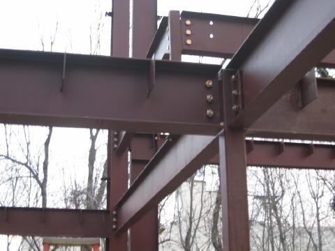


1 Beams Beams are structural members that offer resistance to bending due to applied load 1

2 Beams Long prismatic members Non-prismatic sections also possible Each cross-section dimension Length of member Loading r to the member axis 2

 Deformability required to obtain support reactions")
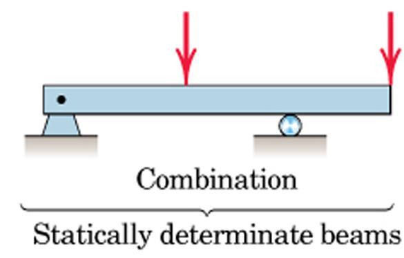
3 Beams Determinacy Statically determinate beam Only equilibrium equations required to obtain support reactions Statically indeterminate beam 3 equilibrium eqs. (1 redundant) Deformability required to obtain support reactions 3 equilibrium eqs. (insufficient) 3


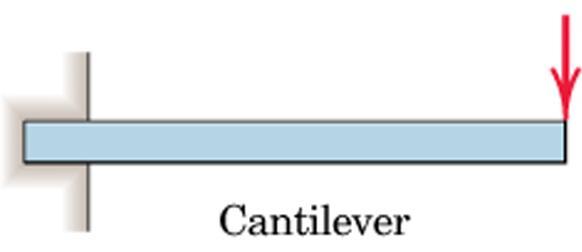
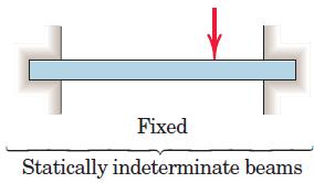
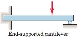
4 Types of Beams Based on support conditions Propped Cantilever 4


5 Types of Beams Based on pattern of external loading Concentrated load Distributed load Intensity (w) expressed force per unit length of beam 5
6 Beams Resultant force (R) on beams? R :: area formed by w and length L over which the load is distributed : R passes through centroid of this area 6

7 Beams Distributed Loads on beams : General Load Distribution Differential increment of force is dr = w dx Total load R is sum of all the differential forces R w dx acting at centroid of the area under consideration x xw dx R Once R is known reactions can be found out from Statics 7

8 Beams: Example Determine the external reactions for the beam R A = 6.96 kn, R B = 9.84 kn 8

9 Beams: Example Determine the external reactions for the beam Dividing the un-symmetric triangular load into two parts with resultants R 1 and R 2 acting at point A and 1m away from point A, respectively. R 1 = 0.5x1.8x2 = 1.8 kn R 2 = 0.5x1.2x2 = 1.2 kn R 1 R 2 F x =0 A x = 1.5sin30 = 0.75 kn A x M A =0 4.8xB y = 1.5cos30x x1.0 B y = kn A y 0.4m B y F y =0 A y = cos A y = kn 9
10 Beams: Example Determine the external reactions for the beam Dividing the trapezoidal load into two parts with resultants R 1 and R 2 R 1 = 24x2.5 = m A R 2 = 0.5x2.5x36=45 kn@4.17m A (distances from A) 60 kn/m M A =0 M A x4.0-60x x4.17=0 M A = 253 knm M A F y =0 A y = 0 A y = -55 kn Downwards 24 kn/m A y R 1 R 2 36 kn/m 10
, Shear Force")
 in Beam Method of Sections is used")
11 Beams Internal Effects Internal Force Resultants Axial Force (N), Shear Force (V), Bending Moment (M), Torsional Moment (T) in Beam Method of Sections is used Axial 11


12 Beams Internal Effects Method of Section: Internal Force Resultants at B Section a-a at B and use equilibrium equations in both cut parts 12

13 Beams Internal Effects 2D Beam 3D Beam The Force Resultants act at the centroid of the section 13


14 Beams Internal Effects Sign Convention Positive Axial Force creates Tension Positive shear force will cause the Beam segment on which it acts to rotate clockwise Positive bending moment will tend to bend the segment on which it acts in a concave upward manner (compression on top of section). 14

 acting on any section is a Couple and has the value of the Bending Moment acting on the")
15 Beams Internal Effects Sign convention in a single plane Interpretation of Bending Couple H-section Beam bent by two equal and opposite positive moments applied at ends Neglecting resistance offered by web Compression at top; Tension at bottom Resultant of these two forces (one tensile and other compressive) acting on any section is a Couple and has the value of the Bending Moment acting on the section. 15


16 Beams Internal Effects Example: Find the axial force in the fixed bar at points B and C Solution: Draw the FBD of the entire bar Draw sections at B and C to get AF in the bar at B and C Alternatively, take a section at C and consider only CD portion of the bar Then take a section at B and consider only BD portion of the bar no need to calculate reactions 16


17 Beams Internal Effects Example: Find the internal torques at points B and C of the circular shaft subjected to three concentrated torques Solution: FBD of entire shaft Sections at B and C and FBDs of shaft segments AB and CD 17
 Solution: Draw FBD of entire beam D y need not be determined if only left part of the beam is")
18 Beams Internal Effects Example: Find the AF, SF, and BM at point B (just to the left of 6 kn) and at point C (just to the right of 6 kn) Solution: Draw FBD of entire beam D y need not be determined if only left part of the beam is analysed 18


19 Beams Internal Effects Example Solution: Draw FBD of segments AB and AC and use equilibrium equations 19
20 Beams SFD and BMD Shear Force Diagram and bending Moment Diagram Variation of SF and BM over the length of the beam SFD and BMD Maximum magnitude of BM and SF and their locations is prime consideration in beam design SFDs and BMDs are plotted using method of section Equilibrium of FBD of entire Beam External Reactions Equilibrium of a cut part of beam Expressions for SF and BM at the cut section Use the positive sign convention consistently 20
21 Beams SFD and BMD Draw SFD and BMD for a cantilever beam supporting a point load at the free end F L/4 L/4 L/4 L/4 +V +F +F +F +F +F +F SFD -V +M M=0 -M -FL -3FL/4 -FL/2 -FL/4 BMD 21
 M dx wdx 2 V dvdx ( M dm) 0 V dm dx Terms w(dx) 2 /2 and dvdx may be dropped since they are differentials of higher order than those which")
22 Beams SFD and BMD Shear and Moment Relationships Consider a portion of a beam Isolate an element dx Draw FBD of the element Vertical equilibrium in dx V w dx (V + dv) = 0 w dv dx Moment equilibrium in dx ( M@ the left side of the element) M dx wdx 2 V dvdx ( M dm) 0 V dm dx Terms w(dx) 2 /2 and dvdx may be dropped since they are differentials of higher order than those which remains. 22
23 Beams SFD and BMD Shear and Moment Relationships w dv dx Slope of the shear diagram = - Value of applied loading V dm dx Slope of the moment curve = Shear Force Both equations not applicable at the point of loading because of discontinuity produced by the abrupt change in shear. 23
24 Beams SFD and BMD Shear and Moment Relationships Expressing V in terms of w by integrating OR V 0 is the shear force at x 0 and V is the shear force at x Expressing M in terms of V by integrating V V 0 M M dv 0 dm x x 0 x x wdx 0 Vdx OR M 0 is the BM at x 0 and M is the BM at x w dv dx V = V 0 + (the negative of the area under the loading curve from x 0 to x) V dm dx M = M 0 + (area under the shear diagram from x 0 to x) 24

25 Beams SFD and BMD V = V 0 + (negative of area under the loading curve from x 0 to x) M = M 0 + (area under the shear diagram from x 0 to x) If there is no externally applied moment M 0 at x 0 = 0, total moment at any section equals the area under the shear diagram up to that section When V passes through zero and is a continuous function of x with dv/dx 0 (i.e., nonzero loading) dm 0 dx BM will be a maximum or minimum at this point Critical values of BM also occur when SF crosses the zero axis discontinuously (Example: Beams under concentrated loads) 25
26 Beams SFD and BMD w V dv dx dm dx Degree of V in x is one higher than that of w Degree of M in x is one higher than that of V Degree of M in x is two higher than that of w Combining the two equations d 2 dx M 2 w If w is a known function of x, BM can be obtained by integrating this equation twice with proper limits of integration. Method is usable only if w is a continuous function of x (other cases not part of this course) 26


27 Beams SFD and BMD: Example Draw the SFD and BMD. Maximum BM occurs where Shear changes the direction Determine reactions at supports. Cut beam at C and consider member AC, V P 2 M Px Cut beam at E and consider member EB, V P 2 L 2 2 M P x For a beam subjected to concentrated loads, shear is constant between loading points and moment varies linearly. 27
dv dx Slope of the shear diagram = - Value of applied loading dm dx Slope of the moment curve = Shear Force
 Beams SFD and BMD Shear and Moment Relationships w dv dx Slope of the shear diagram = - Value of applied loading V dm dx Slope of the moment curve = Shear Force Both equations not applicable at the point
MECHANICS OF MATERIALS. Analysis of Beams for Bending
 MECHANICS OF MATERIALS Analysis of Beams for Bending By NUR FARHAYU ARIFFIN Faculty of Civil Engineering & Earth Resources Chapter Description Expected Outcomes Define the elastic deformation of an axially
Beams are bars of material that support. Beams are common structural members. Beams can support both concentrated and distributed loads
 Outline: Review External Effects on Beams Beams Internal Effects Sign Convention Shear Force and Bending Moment Diagrams (text method) Relationships between Loading, Shear Force and Bending Moments (faster
Chapter 7: Internal Forces
 Chapter 7: Internal Forces Chapter Objectives To show how to use the method of sections for determining the internal loadings in a member. To generalize this procedure by formulating equations that can
Chapter 4.1: Shear and Moment Diagram
 Chapter 4.1: Shear and Moment Diagram Chapter 5: Stresses in Beams Chapter 6: Classical Methods Beam Types Generally, beams are classified according to how the beam is supported and according to crosssection
- Beams are structural member supporting lateral loadings, i.e., these applied perpendicular to the axes.
 4. Shear and Moment functions - Beams are structural member supporting lateral loadings, i.e., these applied perpendicular to the aes. - The design of such members requires a detailed knowledge of the
Unit II Shear and Bending in Beams
 Unit II Shear and Bending in Beams Syllabus: Beams and Bending- Types of loads, supports - Shear Force and Bending Moment Diagrams for statically determinate beam with concentrated load, UDL, uniformly
[8] Bending and Shear Loading of Beams
![[8] Bending and Shear Loading of Beams](/thumbs/92/110949676.jpg "[8] Bending and Shear Loading of Beams") [8] Bending and Shear Loading of Beams Page 1 of 28 [8] Bending and Shear Loading of Beams [8.1] Bending of Beams (will not be covered in class) [8.2] Bending Strain and Stress [8.3] Shear in Straight
[8] Bending and Shear Loading of Beams Page 1 of 28 [8] Bending and Shear Loading of Beams [8.1] Bending of Beams (will not be covered in class) [8.2] Bending Strain and Stress [8.3] Shear in Straight
Mechanics of Materials
 Mechanics of Materials 2. Introduction Dr. Rami Zakaria References: 1. Engineering Mechanics: Statics, R.C. Hibbeler, 12 th ed, Pearson 2. Mechanics of Materials: R.C. Hibbeler, 9 th ed, Pearson 3. Mechanics
Types of Structures & Loads
 Structure Analysis I Chapter 4 1 Types of Structures & Loads 1Chapter Chapter 4 Internal lloading Developed in Structural Members Internal loading at a specified Point In General The loading for coplanar
Stress Analysis Lecture 4 ME 276 Spring Dr./ Ahmed Mohamed Nagib Elmekawy
 Stress Analysis Lecture 4 ME 76 Spring 017-018 Dr./ Ahmed Mohamed Nagib Elmekawy Shear and Moment Diagrams Beam Sign Convention The positive directions are as follows: The internal shear force causes a
Supplement: Statically Indeterminate Trusses and Frames
 : Statically Indeterminate Trusses and Frames Approximate Analysis - In this supplement, we consider an approximate method of solving statically indeterminate trusses and frames subjected to lateral loads
2. Determine the deflection at C of the beam given in fig below. Use principal of virtual work. W L/2 B A L C
 CE-1259, Strength of Materials UNIT I STRESS, STRAIN DEFORMATION OF SOLIDS Part -A 1. Define strain energy density. 2. State Maxwell s reciprocal theorem. 3. Define proof resilience. 4. State Castigliano
Laith Batarseh. internal forces
 Next Previous 1/8/2016 Chapter seven Laith Batarseh Home End Definitions When a member is subjected to external load, an and/or moment are generated inside this member. The value of the generated internal
Shear Force and Bending Moment Diagrams
 Shear Force and Bending Moment Diagrams V [ N ] x[m] M [ Nm] x[m] Competencies 1. Draw shear force and bending moment diagrams for point loads and distributed loads 2. Recognize the position of maximum
BEAM A horizontal or inclined structural member that is designed to resist forces acting to its axis is called a beam
 BEM horizontal or inclined structural member that is designed to resist forces acting to its axis is called a beam INTERNL FORCES IN BEM Whether or not a beam will break, depend on the internal resistances
FIXED BEAMS IN BENDING
 FIXED BEAMS IN BENDING INTRODUCTION Fixed or built-in beams are commonly used in building construction because they possess high rigidity in comparison to simply supported beams. When a simply supported
OUTCOME 1 - TUTORIAL 3 BENDING MOMENTS. You should judge your progress by completing the self assessment exercises. CONTENTS
 Unit 2: Unit code: QCF Level: 4 Credit value: 15 Engineering Science L/601/1404 OUTCOME 1 - TUTORIAL 3 BENDING MOMENTS 1. Be able to determine the behavioural characteristics of elements of static engineering
ENG202 Statics Lecture 16, Section 7.1
 ENG202 Statics Lecture 16, Section 7.1 Internal Forces Developed in Structural Members - Design of any structural member requires an investigation of the loading acting within the member in order to be
Shear Force V: Positive shear tends to rotate the segment clockwise.
 INTERNL FORCES IN EM efore a structural element can be designed, it is necessary to determine the internal forces that act within the element. The internal forces for a beam section will consist of a shear
Chapter 7: Bending and Shear in Simple Beams
 Chapter 7: Bending and Shear in Simple Beams Introduction A beam is a long, slender structural member that resists loads that are generally applied transverse (perpendicular) to its longitudinal axis.
6. Bending CHAPTER OBJECTIVES
 CHAPTER OBJECTIVES Determine stress in members caused by bending Discuss how to establish shear and moment diagrams for a beam or shaft Determine largest shear and moment in a member, and specify where
PDDC 1 st Semester Civil Engineering Department Assignments of Mechanics of Solids [ ] Introduction, Fundamentals of Statics
![PDDC 1 st Semester Civil Engineering Department Assignments of Mechanics of Solids [ ] Introduction, Fundamentals of Statics](/thumbs/92/109382806.jpg "PDDC 1 st Semester Civil Engineering Department Assignments of Mechanics of Solids [ ] Introduction, Fundamentals of Statics") Page1 PDDC 1 st Semester Civil Engineering Department Assignments of Mechanics of Solids [2910601] Introduction, Fundamentals of Statics 1. Differentiate between Scalar and Vector quantity. Write S.I.
Page1 PDDC 1 st Semester Civil Engineering Department Assignments of Mechanics of Solids [2910601] Introduction, Fundamentals of Statics 1. Differentiate between Scalar and Vector quantity. Write S.I.
Chapter 2. Shear Force and Bending Moment. After successfully completing this chapter the students should be able to:
 Chapter Shear Force and Bending Moment This chapter begins with a discussion of beam types. It is also important for students to know and understand the reaction from the types of supports holding the
Mechanics of Structure
 S.Y. Diploma : Sem. III [CE/CS/CR/CV] Mechanics of Structure Time: Hrs.] Prelim Question Paper Solution [Marks : 70 Q.1(a) Attempt any SIX of the following. [1] Q.1(a) Define moment of Inertia. State MI
MECE 3321: Mechanics of Solids Chapter 6
 MECE 3321: Mechanics of Solids Chapter 6 Samantha Ramirez Beams Beams are long straight members that carry loads perpendicular to their longitudinal axis Beams are classified by the way they are supported
Determinate portal frame
 eterminate portal frame onsider the frame shown in the figure below with the aim of calculating the bending moment diagram (M), shear force diagram (SF), and axial force diagram (F). P H y R x x R y L
8-5 Conjugate-Beam method. 8-5 Conjugate-Beam method. 8-5 Conjugate-Beam method. 8-5 Conjugate-Beam method
 The basis for the method comes from the similarity of eqn.1 &. to eqn 8. & 8. To show this similarity, we can write these eqn as shown dv dx w d θ M dx d M w dx d v M dx Here the shear V compares with
Bending Stress. Sign convention. Centroid of an area
 Bending Stress Sign convention The positive shear force and bending moments are as shown in the figure. Centroid of an area Figure 40: Sign convention followed. If the area can be divided into n parts
REVIEW FOR EXAM II. Dr. Ibrahim A. Assakkaf SPRING 2002
 REVIEW FOR EXM II. J. Clark School of Engineering Department of Civil and Environmental Engineering b Dr. Ibrahim. ssakkaf SPRING 00 ENES 0 Mechanics of Materials Department of Civil and Environmental
SAB2223 Mechanics of Materials and Structures
 S2223 Mechanics of Materials and Structures TOPIC 2 SHER FORCE ND ENDING MOMENT Lecturer: Dr. Shek Poi Ngian TOPIC 2 SHER FORCE ND ENDING MOMENT Shear Force and ending Moment Introduction Types of beams
Mechanics of Materials II. Chapter III. A review of the fundamental formulation of stress, strain, and deflection
 Mechanics of Materials II Chapter III A review of the fundamental formulation of stress, strain, and deflection Outline Introduction Assumtions and limitations Axial loading Torsion of circular shafts
Internal Internal Forces Forces
 Internal Forces ENGR 221 March 19, 2003 Lecture Goals Internal Force in Structures Shear Forces Bending Moment Shear and Bending moment Diagrams Internal Forces and Bending The bending moment, M. Moment
ENGINEERING MECHANICS SOLUTIONS UNIT-I
 LONG QUESTIONS ENGINEERING MECHANICS SOLUTIONS UNIT-I 1. A roller shown in Figure 1 is mass 150 Kg. What force P is necessary to start the roller over the block A? =90+25 =115 = 90+25.377 = 115.377 = 360-(115+115.377)
R13. II B. Tech I Semester Regular Examinations, Jan MECHANICS OF SOLIDS (Com. to ME, AME, AE, MTE) PART-A
 PART-A") SET - 1 II B. Tech I Semester Regular Examinations, Jan - 2015 MECHANICS OF SOLIDS (Com. to ME, AME, AE, MTE) Time: 3 hours Max. Marks: 70 Note: 1. Question Paper consists of two parts (Part-A and Part-B)
SET - 1 II B. Tech I Semester Regular Examinations, Jan - 2015 MECHANICS OF SOLIDS (Com. to ME, AME, AE, MTE) Time: 3 hours Max. Marks: 70 Note: 1. Question Paper consists of two parts (Part-A and Part-B)
UNIT I ENERGY PRINCIPLES
 UNIT I ENERGY PRINCIPLES Strain energy and strain energy density- strain energy in traction, shear in flexure and torsion- Castigliano s theorem Principle of virtual work application of energy theorems
CHAPTER 6: Shearing Stresses in Beams
 (130) CHAPTER 6: Shearing Stresses in Beams When a beam is in pure bending, the only stress resultants are the bending moments and the only stresses are the normal stresses acting on the cross sections.
ENR202 Mechanics of Materials Lecture 4A Notes and Slides
 Slide 1 Copyright Notice Do not remove this notice. COMMMONWEALTH OF AUSTRALIA Copyright Regulations 1969 WARNING This material has been produced and communicated to you by or on behalf of the University
CIV100 Mechanics. Module 5: Internal Forces and Design. by: Jinyue Zhang. By the end of this Module you should be able to:
 CIV100 Mechanics Module 5: Internal Forces and Design by: Jinyue Zhang Module Objective By the end of this Module you should be able to: Find internal forces of any structural members Understand how Shear
2 marks Questions and Answers
 1. Define the term strain energy. A: Strain Energy of the elastic body is defined as the internal work done by the external load in deforming or straining the body. 2. Define the terms: Resilience and
Bending Internal Forces.
 ending Internal orces mi@seu.edu.cn Contents Introduction( 弯曲变形简介 ) The orms of Internal orces in eams( 梁中内力的形式 ) Symmetric ending( 对称弯曲 ) Types of eams( 静定梁的分类 ) Types of Supports and Reactions( 梁的支撑种类及相应的支座反力形式
CHAPTER 5 Statically Determinate Plane Trusses
 CHAPTER 5 Statically Determinate Plane Trusses TYPES OF ROOF TRUSS TYPES OF ROOF TRUSS ROOF TRUSS SETUP ROOF TRUSS SETUP OBJECTIVES To determine the STABILITY and DETERMINACY of plane trusses To analyse
PURE BENDING. If a simply supported beam carries two point loads of 10 kn as shown in the following figure, pure bending occurs at segment BC.
 BENDING STRESS The effect of a bending moment applied to a cross-section of a beam is to induce a state of stress across that section. These stresses are known as bending stresses and they act normally
CHAPTER 5 Statically Determinate Plane Trusses TYPES OF ROOF TRUSS
 CHAPTER 5 Statically Determinate Plane Trusses TYPES OF ROOF TRUSS 1 TYPES OF ROOF TRUSS ROOF TRUSS SETUP 2 ROOF TRUSS SETUP OBJECTIVES To determine the STABILITY and DETERMINACY of plane trusses To analyse
ENGINEERING COUNCIL DIPLOMA LEVEL MECHANICS OF SOLIDS D209 TUTORIAL 3 - SHEAR FORCE AND BENDING MOMENTS IN BEAMS
 ENGINEERING COUNCIL DIPLOMA LEVEL MECHANICS OF SOLIDS D209 TUTORIAL 3 - SHEAR FORCE AND BENDING MOMENTS IN BEAMS You should judge your progress by completing the self assessment exercises. On completion
MAHALAKSHMI ENGINEERING COLLEGE
 CE840-STRENGTH OF TERIS - II PGE 1 HKSHI ENGINEERING COEGE TIRUCHIRPI - 611. QUESTION WITH NSWERS DEPRTENT : CIVI SEESTER: IV SU.CODE/ NE: CE 840 / Strength of aterials -II UNIT INDETERINTE ES 1. Define
Module 2. Analysis of Statically Indeterminate Structures by the Matrix Force Method
 Module 2 Analysis of Statically Indeterminate Structures by the Matrix Force Method Lesson 8 The Force Method of Analysis: Beams Instructional Objectives After reading this chapter the student will be
Consider an elastic spring as shown in the Fig.2.4. When the spring is slowly
 .3 Strain Energy Consider an elastic spring as shown in the Fig..4. When the spring is slowly pulled, it deflects by a small amount u 1. When the load is removed from the spring, it goes back to the original
Members Subjected to Combined Loads
 Members Subjected to Combined Loads Combined Bending & Twisting : In some applications the shaft are simultaneously subjected to bending moment M and Torque T.The Bending moment comes on the shaft due
CE6306 STRENGTH OF MATERIALS TWO MARK QUESTIONS WITH ANSWERS ACADEMIC YEAR
 CE6306 STRENGTH OF MATERIALS TWO MARK QUESTIONS WITH ANSWERS ACADEMIC YEAR 2014-2015 UNIT - 1 STRESS, STRAIN AND DEFORMATION OF SOLIDS PART- A 1. Define tensile stress and tensile strain. The stress induced
Unit Workbook 1 Level 4 ENG U8 Mechanical Principles 2018 UniCourse Ltd. All Rights Reserved. Sample
 Pearson BTEC Levels 4 Higher Nationals in Engineering (RQF) Unit 8: Mechanical Principles Unit Workbook 1 in a series of 4 for this unit Learning Outcome 1 Static Mechanical Systems Page 1 of 23 1.1 Shafts
 techie-touch.blogspot.com DEPARTMENT OF CIVIL ENGINEERING ANNA UNIVERSITY QUESTION BANK CE 2302 STRUCTURAL ANALYSIS-I TWO MARK QUESTIONS UNIT I DEFLECTION OF DETERMINATE STRUCTURES 1. Write any two important
Symmetric Bending of Beams
 Symmetric Bending of Beams beam is any long structural member on which loads act perpendicular to the longitudinal axis. Learning objectives Understand the theory, its limitations and its applications
STATICALLY INDETERMINATE STRUCTURES
 STATICALLY INDETERMINATE STRUCTURES INTRODUCTION Generally the trusses are supported on (i) a hinged support and (ii) a roller support. The reaction components of a hinged support are two (in horizontal
Chapter 4 Deflection and Stiffness
 Chapter 4 Deflection and Stiffness Asst. Prof. Dr. Supakit Rooppakhun Chapter Outline Deflection and Stiffness 4-1 Spring Rates 4-2 Tension, Compression, and Torsion 4-3 Deflection Due to Bending 4-4 Beam
Engineering Mechanics Department of Mechanical Engineering Dr. G. Saravana Kumar Indian Institute of Technology, Guwahati
 Engineering Mechanics Department of Mechanical Engineering Dr. G. Saravana Kumar Indian Institute of Technology, Guwahati Module 3 Lecture 6 Internal Forces Today, we will see analysis of structures part
OUT ON A LIMB AND HUNG OUT TO DRY :
 27-Nov-12 17:03 1 of 2 h p://edugen.wileyplus.com/edugen/courses/crs1404/pc/c10/c2hlchbhcmq3mjewyzewxzeuegzvcm0.enc?course=crs1404&id=ref CHAPTER 10 OUT ON A LIMB AND HUNG OUT TO DRY : A LOOK AT INTERNAL
Strength of Materials Prof. S.K.Bhattacharya Dept. of Civil Engineering, I.I.T., Kharagpur Lecture No.26 Stresses in Beams-I
 Strength of Materials Prof. S.K.Bhattacharya Dept. of Civil Engineering, I.I.T., Kharagpur Lecture No.26 Stresses in Beams-I Welcome to the first lesson of the 6th module which is on Stresses in Beams
SSC-JE MAINS ONLINE TEST SERIES / CIVIL ENGINEERING SOM + TOS
 SSC-JE MAINS ONLINE TEST SERIES / CIVIL ENGINEERING SOM + TOS Time Allowed:2 Hours Maximum Marks: 300 Attention: 1. Paper consists of Part A (Civil & Structural) Part B (Electrical) and Part C (Mechanical)
DESIGN AND DETAILING OF COUNTERFORT RETAINING WALL
 DESIGN AND DETAILING OF COUNTERFORT RETAINING WALL When the height of the retaining wall exceeds about 6 m, the thickness of the stem and heel slab works out to be sufficiently large and the design becomes
8.3 Shear and Bending-Moment Diagrams Constructed by Areas
 8.3 Shear and ending-moment Diagrams Constructed by reas 8.3 Shear and ending-moment Diagrams Constructed by reas Procedures and Strategies, page 1 of 3 Procedures and Strategies for Solving Problems Involving
five moments ELEMENTS OF ARCHITECTURAL STRUCTURES: FORM, BEHAVIOR, AND DESIGN DR. ANNE NICHOLS SPRING 2014 lecture ARCH 614
 ELEMENTS OF ARCHITECTURAL STRUCTURES: FORM, BEHAVIOR, AND DESIGN DR. ANNE NICHOLS SPRING 2014 lecture five moments Moments 1 Moments forces have the tendency to make a body rotate about an axis http://www.physics.umd.edu
Chapter 2: Deflections of Structures
 Chapter 2: Deflections of Structures Fig. 4.1. (Fig. 2.1.) ASTU, Dept. of C Eng., Prepared by: Melkamu E. Page 1 (2.1) (4.1) (2.2) Fig.4.2 Fig.2.2 ASTU, Dept. of C Eng., Prepared by: Melkamu E. Page 2
Chapter 11. Displacement Method of Analysis Slope Deflection Method
 Chapter 11 Displacement ethod of Analysis Slope Deflection ethod Displacement ethod of Analysis Two main methods of analyzing indeterminate structure Force method The method of consistent deformations
Discontinuous Distributions in Mechanics of Materials
 Discontinuous Distributions in Mechanics of Materials J.E. Akin, Rice University 1. Introduction The study of the mechanics of materials continues to change slowly. The student needs to learn about software
Shear force and bending moment of beams 2.1 Beams 2.2 Classification of beams 1. Cantilever Beam Built-in encastre' Cantilever
 CHAPTER TWO Shear force and bending moment of beams 2.1 Beams A beam is a structural member resting on supports to carry vertical loads. Beams are generally placed horizontally; the amount and extent of
7.4 The Elementary Beam Theory
 7.4 The Elementary Beam Theory In this section, problems involving long and slender beams are addressed. s with pressure vessels, the geometry of the beam, and the specific type of loading which will be
Supplement: Statically Indeterminate Frames
 : Statically Indeterminate Frames Approximate Analysis - In this supplement, we consider another approximate method of solving statically indeterminate frames subjected to lateral loads known as the. Like
Module 3. Analysis of Statically Indeterminate Structures by the Displacement Method
 odule 3 Analysis of Statically Indeterminate Structures by the Displacement ethod Lesson 16 The Slope-Deflection ethod: rames Without Sidesway Instructional Objectives After reading this chapter the student
Chapter 7 FORCES IN BEAMS AND CABLES
 hapter 7 FORES IN BEAMS AN ABLES onsider a straight two-force member AB subjected at A and B to equal and opposite forces F and -F directed along AB. utting the member AB at and drawing the free-body B
SIGN CONVENTION OF STRESS RESULTANTS
 SIGN CONVENTION OF STRESS RESULTANTS A quick guide to understanding the sign conventions used in the ush Me ull Me models National HE STEM rogramme INTRODUCTION Representing stress resultants graphically
CHAPTER 8 BENDING MOMENT AND SHEAR FORCE DIAGRAMS
 CHPTE 8 BENDING MOMENT ND SHE FOCE DIGMS EXECISE 5, Page. Determine expressions for the bending moment and shearing force distributions for the following simply supported beam; hence, or otherwise, plot
Comb resonator design (2)
") Lecture 6: Comb resonator design () -Intro Intro. to Mechanics of Materials School of Electrical l Engineering i and Computer Science, Seoul National University Nano/Micro Systems & Controls Laboratory
Lecture 6: Comb resonator design () -Intro Intro. to Mechanics of Materials School of Electrical l Engineering i and Computer Science, Seoul National University Nano/Micro Systems & Controls Laboratory
 UNIT III DEFLECTION OF BEAMS 1. What are the methods for finding out the slope and deflection at a section? The important methods used for finding out the slope and deflection at a section in a loaded
Indeterminate Analysis Force Method 1
 Indeterminate Analysis Force Method 1 The force (flexibility) method expresses the relationships between displacements and forces that exist in a structure. Primary objective of the force method is to
PERIYAR CENTENARY POLYTECHNIC COLLEGE PERIYAR NAGAR - VALLAM THANJAVUR. DEPARTMENT OF MECHANICAL ENGINEERING QUESTION BANK
 PERIYAR CENTENARY POLYTECHNIC COLLEGE PERIYAR NAGAR - VALLAM - 613 403 - THANJAVUR. DEPARTMENT OF MECHANICAL ENGINEERING QUESTION BANK Sub : Strength of Materials Year / Sem: II / III Sub Code : MEB 310
Procedure for drawing shear force and bending moment diagram:
 Procedure for drawing shear force and bending moment diagram: Preamble: The advantage of plotting a variation of shear force F and bending moment M in a beam as a function of x' measured from one end of
QUESTION BANK DEPARTMENT: CIVIL SEMESTER: III SUBJECT CODE: CE2201 SUBJECT NAME: MECHANICS OF SOLIDS UNIT 1- STRESS AND STRAIN PART A
 DEPARTMENT: CIVIL SUBJECT CODE: CE2201 QUESTION BANK SEMESTER: III SUBJECT NAME: MECHANICS OF SOLIDS UNIT 1- STRESS AND STRAIN PART A (2 Marks) 1. Define longitudinal strain and lateral strain. 2. State
Sub. Code:
 Important Instructions to examiners: ) The answers should be examined by key words and not as word-to-word as given in the model answer scheme. ) The model answer and the answer written by candidate may
Assumptions: beam is initially straight, is elastically deformed by the loads, such that the slope and deflection of the elastic curve are
 *12.4 SLOPE & DISPLACEMENT BY THE MOMENT-AREA METHOD Assumptions: beam is initially straight, is elastically deformed by the loads, such that the slope and deflection of the elastic curve are very small,
ENG2000 Chapter 7 Beams. ENG2000: R.I. Hornsey Beam: 1
 ENG2000 Chapter 7 Beams ENG2000: R.I. Hornsey Beam: 1 Overview In this chapter, we consider the stresses and moments present in loaded beams shear stress and bending moment diagrams We will also look at
CHAPTER OBJECTIVES CHAPTER OUTLINE. 4. Axial Load
 CHAPTER OBJECTIVES Determine deformation of axially loaded members Develop a method to find support reactions when it cannot be determined from euilibrium euations Analyze the effects of thermal stress
UNIT-I STRESS, STRAIN. 1. A Member A B C D is subjected to loading as shown in fig determine the total elongation. Take E= 2 x10 5 N/mm 2
 UNIT-I STRESS, STRAIN 1. A Member A B C D is subjected to loading as shown in fig determine the total elongation. Take E= 2 x10 5 N/mm 2 Young s modulus E= 2 x10 5 N/mm 2 Area1=900mm 2 Area2=400mm 2 Area3=625mm
CHAPTER -6- BENDING Part -1-
 Ishik University / Sulaimani Civil Engineering Department Mechanics of Materials CE 211 CHAPTER -6- BENDING Part -1-1 CHAPTER -6- Bending Outlines of this chapter: 6.1. Chapter Objectives 6.2. Shear and
P.E. Civil Exam Review:
 P.E. Civil Exam Review: Structural Analysis J.P. Mohsen Email: jpm@louisville.edu Structures Determinate Indeterminate STATICALLY DETERMINATE STATICALLY INDETERMINATE Stability and Determinacy of Trusses
Mechanics in Energy Resources Engineering - Chapter 5 Stresses in Beams (Basic topics)
") Week 7, 14 March Mechanics in Energy Resources Engineering - Chapter 5 Stresses in Beams (Basic topics) Ki-Bok Min, PhD Assistant Professor Energy Resources Engineering i Seoul National University Shear
Week 7, 14 March Mechanics in Energy Resources Engineering - Chapter 5 Stresses in Beams (Basic topics) Ki-Bok Min, PhD Assistant Professor Energy Resources Engineering i Seoul National University Shear
LECTURE 14 Strength of a Bar in Transverse Bending. 1 Introduction. As we have seen, only normal stresses occur at cross sections of a rod in pure
 V. DEMENKO MECHNCS OF MTERLS 015 1 LECTURE 14 Strength of a Bar in Transverse Bending 1 ntroduction s we have seen, onl normal stresses occur at cross sections of a rod in pure bending. The corresponding
MECE 3321 MECHANICS OF SOLIDS CHAPTER 1
 MECE 3321 MECHANICS O SOLIDS CHAPTER 1 Samantha Ramirez, MSE WHAT IS MECHANICS O MATERIALS? Rigid Bodies Statics Dynamics Mechanics Deformable Bodies Solids/Mech. Of Materials luids 1 WHAT IS MECHANICS
Deflection of Flexural Members - Macaulay s Method 3rd Year Structural Engineering
 Deflection of Flexural Members - Macaulay s Method 3rd Year Structural Engineering 008/9 Dr. Colin Caprani 1 Contents 1. Introduction... 3 1.1 General... 3 1. Background... 4 1.3 Discontinuity Functions...
By Dr. Mohammed Ramidh
 Engineering Materials Design Lecture.6 the design of beams By Dr. Mohammed Ramidh 6.1 INTRODUCTION Finding the shear forces and bending moments is an essential step in the design of any beam. we usually
Determine the resultant internal loadings acting on the cross section at C of the beam shown in Fig. 1 4a.
 E X M P L E 1.1 Determine the resultant internal loadings acting on the cross section at of the beam shown in Fig. 1 a. 70 N/m m 6 m Fig. 1 Support Reactions. This problem can be solved in the most direct
Deflection of Flexural Members - Macaulay s Method 3rd Year Structural Engineering
 Deflection of Flexural Members - Macaulay s Method 3rd Year Structural Engineering 009/10 Dr. Colin Caprani 1 Contents 1. Introduction... 4 1.1 General... 4 1. Background... 5 1.3 Discontinuity Functions...
QUESTION BANK SEMESTER: III SUBJECT NAME: MECHANICS OF SOLIDS
 QUESTION BANK SEMESTER: III SUBJECT NAME: MECHANICS OF SOLIDS UNIT 1- STRESS AND STRAIN PART A (2 Marks) 1. Define longitudinal strain and lateral strain. 2. State Hooke s law. 3. Define modular ratio,
UNIT-V MOMENT DISTRIBUTION METHOD
 UNIT-V MOMENT DISTRIBUTION METHOD Distribution and carryover of moments Stiffness and carry over factors Analysis of continuous beams Plane rigid frames with and without sway Neylor s simplification. Hardy
UNIT 1 STRESS STRAIN AND DEFORMATION OF SOLIDS, STATES OF STRESS 1. Define stress. When an external force acts on a body, it undergoes deformation.
 UNIT 1 STRESS STRAIN AND DEFORMATION OF SOLIDS, STATES OF STRESS 1. Define stress. When an external force acts on a body, it undergoes deformation. At the same time the body resists deformation. The magnitude
CHAPTER OBJECTIVES Use various methods to determine the deflection and slope at specific pts on beams and shafts: 2. Discontinuity functions
 1. Deflections of Beams and Shafts CHAPTER OBJECTIVES Use various methods to determine the deflection and slope at specific pts on beams and shafts: 1. Integration method. Discontinuity functions 3. Method
Free Body Diagram: Solution: The maximum load which can be safely supported by EACH of the support members is: ANS: A =0.217 in 2
 Problem 10.9 The angle β of the system in Problem 10.8 is 60. The bars are made of a material that will safely support a tensile normal stress of 8 ksi. Based on this criterion, if you want to design the
Module 4 : Deflection of Structures Lecture 4 : Strain Energy Method
 Module 4 : Deflection of Structures Lecture 4 : Strain Energy Method Objectives In this course you will learn the following Deflection by strain energy method. Evaluation of strain energy in member under
STRESS STRAIN AND DEFORMATION OF SOLIDS, STATES OF STRESS
 1 UNIT I STRESS STRAIN AND DEFORMATION OF SOLIDS, STATES OF STRESS 1. Define: Stress When an external force acts on a body, it undergoes deformation. At the same time the body resists deformation. The
Chapter Objectives. Copyright 2011 Pearson Education South Asia Pte Ltd
 Chapter Objectives To generalize the procedure by formulating equations that can be plotted so that they describe the internal shear and moment throughout a member. To use the relations between distributed