Lecture Slides. Chapter 4. Deflection and Stiffness. The McGraw-Hill Companies 2012
|
|
|
- Winifred Nichols
- 5 years ago
- Views:
Transcription


1 Lecture Slides Chapter 4 Deflection and Stiffness The McGraw-Hill Companies 2012

2 Chapter Outline
3 Force vs Deflection Elasticity property of a material that enables it to regain its original configuration after deformation Spring a mechanical element that exerts a force when deformed Linear spring Nonlinear stiffening spring Nonlinear softening spring Fig. 4 1
4 Spring Rate Relation between force and deflection, F = F(y) Spring rate For linear springs, k is constant, called spring constant
5 Axially-Loaded Stiffness Total extension or contraction of a uniform bar in tension or compression Spring constant, with k = F/d
6 Torsionally-Loaded Stiffness Angular deflection (in radians) of a uniform solid or hollow round bar subjected to a twisting moment T Converting to degrees, and including J = pd 4 /32 for round solid Torsional spring constant for round bar
7 Deflection Due to Bending Curvature of beam subjected to bending moment M From mathematics, curvature of plane curve Slope of beam at any point x along the length If the slope is very small, the denominator of Eq. (4-9) approaches unity. Combining Eqs. (4-8) and (4-9), for beams with small slopes,
8 Recall Eqs. (3-3) and (3-4) Deflection Due to Bending Successively differentiating
9 Deflection Due to Bending Fig. 4 2 (4-10) (4-11) (4-12) (4-13) (4-14)

10 Example 4-1 Fig. 4 2

11 Example 4-1

12 Example 4-1

13 Example 4-1
14 Beam Deflection Methods Some of the more common methods for solving the integration problem for beam deflection Superposition Moment-area method Singularity functions Numerical integration Other methods that use alternate approaches Castigliano energy method Finite element software
15 Beam Deflection by Superposition Superposition determines the effects of each load separately, then adds the results. Separate parts are solved using any method for simple load cases. Many load cases and boundary conditions are solved and available in Table A-9, or in references such as Roark s Formulas for Stress and Strain. Conditions Each effect is linearly related to the load that produces it. A load does not create a condition that affects the result of another load. The deformations resulting from any specific load are not large enough to appreciably alter the geometric relations of the parts of the structural system.

16 Example 4-2 Fig. 4 3
17 Example 4-2

18 Example 4-2

19 Example 4-3 Fig. 4 4

20 Example 4-3

21 Example 4-3 Fig. 4 4

22 Example 4-3

23 Example 4-4 Fig. 4 5

24 Example 4-4

25 Example 4-4
26 A notation useful for integrating across discontinuities Beam Deflection by Singularity Functions Angle brackets indicate special function to determine whether forces and moments are active Table 3 1
27 Example 4-5

28 Example 4-5

29 Example 4-5

30 Example 4-5

31 Example 4-6 Fig. 4 6

32 Example 4-6

33 Example 4-6

34 Example 4-6

35 Example 4-7 Fig. 4 7

36 Example 4-7 Fig. 4 7

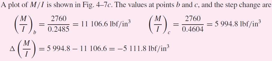
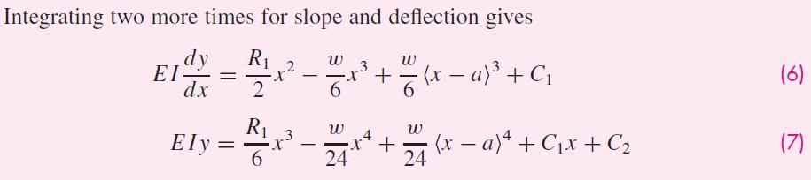
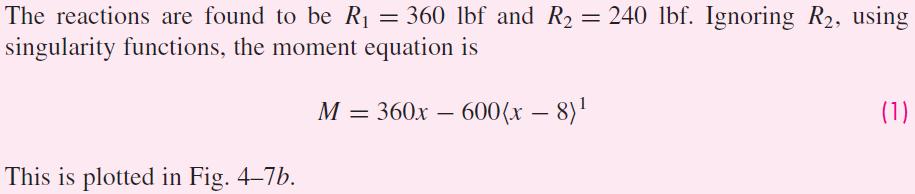
37 Example 4-7

38 Example 4-7

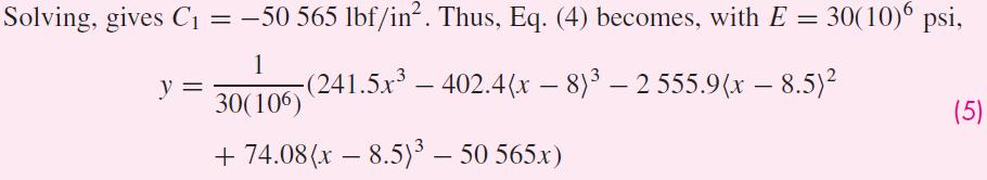
39 Example 4-7

40 Example 4-7

41 Example 4-7

42 Example 4-7
43 Strain Energy External work done on elastic member in deforming it is transformed into strain energy, or potential energy. Strain energy equals product of average force and deflection.
44 Some Common Strain Energy Formulas For axial loading, applying k = AE/l from Eq. (4-4), For torsional loading, applying k = GJ/l from Eq. (4-7),
45 Some Common Strain Energy Formulas For direct shear loading, For bending loading,

46 Some Common Strain Energy Formulas For transverse shear loading, where C is a modifier dependent on the cross sectional shape.
47 Summary of Common Strain Energy Formulas

48 Example 4-8 Fig. 4 9

49 Example 4-8 Fig. 4 9

50 Example 4-8
51 Castigliano s Theorem When forces act on elastic systems subject to small displacements, the displacement corresponding to any force, in the direction of the force, is equal to the partial derivative of the total strain energy with respect to that force. For rotational displacement, in radians,
52 Example 4-9 Fig. 4 9

53 Example 4-9
54 Utilizing a Fictitious Force Castigliano s method can be used to find a deflection at a point even if there is no force applied at that point. Apply a fictitious force Q at the point, and in the direction, of the desired deflection. Set up the equation for total strain energy including the energy due to Q. Take the derivative of the total strain energy with respect to Q. Once the derivative is taken, Q is no longer needed and can be set to zero.
55 Finding Deflection Without Finding Energy For cases requiring integration of strain energy equations, it is more efficient to obtain the deflection directly without explicitly finding the strain energy. The partial derivative is moved inside the integral. For example, for bending, Derivative can be taken before integration, simplifying the math. Especially helpful with fictitious force Q, since it can be set to zero after the derivative is taken.
56 Common Deflection Equations
57 Example 4-10 Fig. 4 10

58 Example 4-10

59 Example 4-10

60 Example 4-10

61 Example 4-11 Fig. 4 11
62 Example 4-11 Fig. 4 11


63 Example 4-11 Fig. 4 11

64 Example 4-11 Fig. 4 11

65 Example 4-11 Fig. 4 11

66 Example 4-11 Fig. 4 11

67 Example 4-11 Fig. 4 11
68 Deflection of Curved Members Consider case of thick curved member in bending (See Sec. 3-18) Four strain energy terms due to Bending moment M Axial force F q Bending moment due to F q (since neutral axis and centroidal axis do not coincide) Transverse shear F r Fig. 4 12
69 Deflection of Curved Members Strain energy due to bending moment M where r n is the radius of the neutral axis Fig. 4 12
70 Deflection of Curved Members Strain energy due to axial force F q Fig. 4 12
71 Deflection of Curved Members Strain energy due to bending moment due to F q Fig. 4 12

72 Deflection of Curved Members Strain energy due to transverse shear F r Fig. 4 12
73 Combining four energy terms Deflection of Curved Members Deflection by Castigliano s method General for any thick circular curved member, with appropriate limits of integration
74 Deflection of Curved Members For specific example in figure, Fig. 4 12
75 Substituting and factoring, Deflection of Curved Members Fig. 4 12
76 Deflection of Thin Curved Members For thin curved members, say R/h > 10, eccentricity is small Strain energies can be approximated with regular energy equations with substitution of Rdq for dx As R increases, bending component dominates all other terms

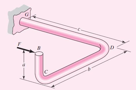
77 Example 4-12 Fig. 4 13

78 Example 4-12 Fig. 4 13

79 Example 4-12

80 Example 4-12

81 Example 4-12

82 Example 4-12

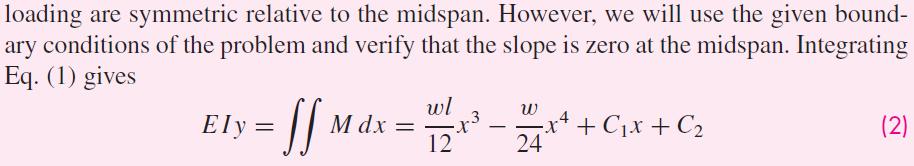
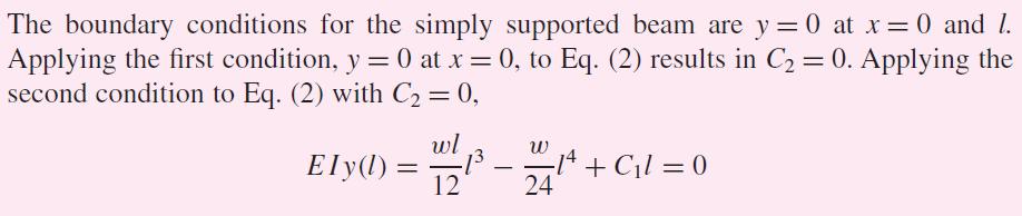
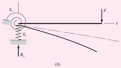
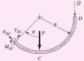
83 Example 4-13
84 Example 4-13 Fig. 4 14

85 Example 4-13

86 Example 4-13

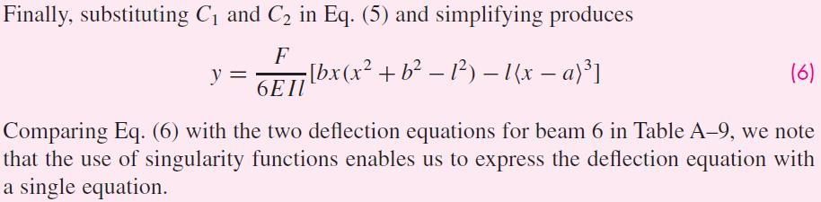
87 Example 4-13 Fig (b)
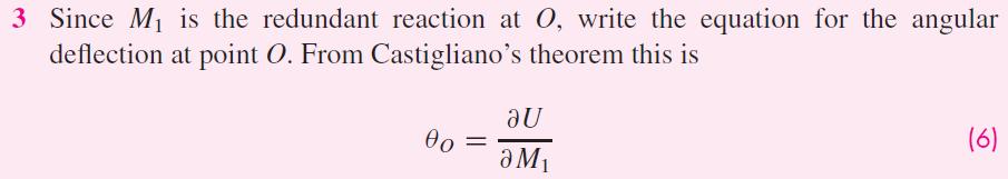
88 Statically Indeterminate Problems A system is overconstrained when it has more unknown support (reaction) forces and/or moments than static equilibrium equations. Such a system is said to be statically indeterminate. The extra constraint supports are call redundant supports. To solve, a deflection equation is required for each redundant support.
89 Example of nested springs One equation of static equilibrium Statically Indeterminate Problems Deformation equation Use spring constant relation to put deflection equation in terms of force Substituting into equilibrium equation, Fig. 4 15
90 Procedure 1 for Statically Indeterminate Problems 1. Choose the redundant reaction(s) 2. Write the equations of static equilibrium for the remaining reactions in terms of the applied loads and the redundant reaction(s). 3. Write the deflection equation(s) for the point(s) at the locations of the redundant reaction(s) in terms of the applied loads and redundant reaction(s). 4. Solve equilibrium equations and deflection equations simultaneously to determine the reactions.

91 Example 4-14 Fig. 4 16

92 Example 4-14

93 Example 4-14

94 Example 4-14

95 Example 4-14

96 Example 4-14

97 Example 4-14
98 Procedure 2 for Statically Indeterminate Problems 1. Write the equations of static equilibrium in terms of the applied loads and unknown restraint reactions. 2. Write the deflection equation in terms of the applied loads and unknown restraint reactions. 3. Apply boundary conditions to the deflection equation consistent with the restraints. 4. Solve the set of equations.

99 Example 4-15 Fig. 4 17

100 Example 4-15 Fig. 4 17

101 Example 4-15

102 Example 4-15

103 Example 4-15

104 Example 4-15

105 Example 4-15
106 Compression Members Column A member loaded in compression such that either its length or eccentric loading causes it to experience more than pure compression Four categories of columns Long columns with central loading Intermediate-length columns with central loading Columns with eccentric loading Struts or short columns with eccentric loading
107 When P reaches critical load, column becomes unstable and bending develops rapidly Long Columns with Central Loading Critical load depends on end conditions Fig. 4 18
108 For pin-ended column, critical load is given by Euler column formula, Applies to other end conditions with addition of constant C for each end condition Euler Column Formula (4-42) (4-43) Fig. 4 18

109 Recommended Values for End Condition Constant Fixed ends are practically difficult to achieve More conservative values of C are often used, as in Table 4-2 Table 4 2
110 Long Columns with Central Loading Using I = Ak 2, where A is the area and k is the radius of gyration, Euler column formula can be expressed as l/k is the slenderness ratio, used to classify columns according to length categories. P cr /A is the critical unit load, the load per unit area necessary to place the column in a condition of unstable equilibrium.
111 Euler Curve Plotting P cr /A vs l/k, with C = 1 gives curve PQR Fig. 4 19
112 Long Columns with Central Loading Tests show vulnerability to failure near point Q Since buckling is sudden and catastrophic, a conservative approach near Q is desired Point T is usually defined such that P cr /A = S y /2, giving Fig. 4 19
113 Condition for Use of Euler Equation For (l/k) > (l/k) 1, use Euler equation For (l/k) (l/k) 1, use a parabolic curve between S y and T Fig. 4 19
114 Intermediate-Length Columns with Central Loading For intermediate-length columns, where (l/k) (l/k) 1, use a parabolic curve between S y and T General form of parabola If parabola starts at S y, then a = S y If parabola fits tangent to Euler curve at T, then Fig Results in parabolic formula, also known as J.B. Johnson formula
115 Columns with Eccentric Loading For eccentrically loaded column with eccentricity e, M = -P(e+y) Substituting into d 2 y/dx 2 =M/EI, Solving with boundary conditions y = 0 at x = 0 and at x = l Fig. 4 20
116 At midspan where x = l/2 Columns with Eccentric Loading Fig. 4 20
117 Columns with Eccentric Loading The maximum compressive stress includes axial and bending Substituting M max from Eq. (4-48) Using S yc as the maximum value of s c, and solving for P/A, we obtain the secant column formula
118 Secant Column Formula Secant Column Formula ec/k 2 is the eccentricity ratio Design charts of secant column formula for various eccentricity ratio can be prepared for a given material strength Fig. 4 21

119 Example 4-16

120 Example 4-16

121 Example 4-17

122 Example 4-17

123 Example 4-18

124 Example 4-19
125 Example 4-19
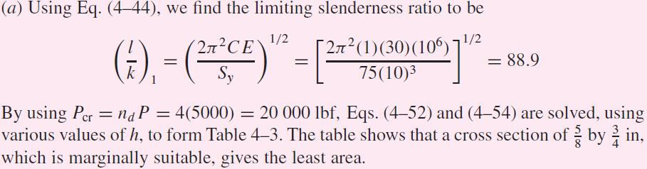
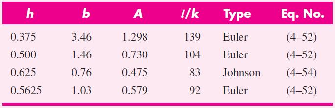
126 Struts or Short Compression Members Strut - short member loaded in compression If eccentricity exists, maximum stress is at B with axial compression and bending. Note that it is not a function of length Differs from secant equation in that it assumes small effect of bending deflection If bending deflection is limited to 1 percent of e, then from Eq. (4-44), the limiting slenderness ratio for strut is Fig. 4 22

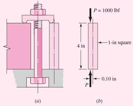
127 Example 4-20 Fig. 4 23

128 Example 4-20
 Long or thin Unbraced Instability may be Local or global Elastic or plastic Bending or torsion Fig. 4 24 Fig.")
129 Elastic Stability Be alert for buckling instability in structural members that are Loaded in compression (directly or indirectly) Long or thin Unbraced Instability may be Local or global Elastic or plastic Bending or torsion Fig Fig. 4 25
130 Shock and Impact Impact collision of two masses with initial relative velocity Shock a suddenly applied force or disturbance

131 Shock and Impact Example of automobile collision m 1 is mass of engine m 2 is mass of rest of vehicle Springs represent stiffnesses of various structural elements Equations of motion, assuming linear springs Equations can be solved for any impact velocity Fig. 4 26
132 Weight falls distance h and suddenly applies a load to a cantilever beam Find deflection and force applied to the beam due to impact Suddenly Applied Loading Fig (a)
133 Suddenly Applied Loading Abstract model considering beam as simple spring From Table A-9, beam 1, k= F/y =3EI/l 3 Assume the beam to be massless, so no momentum transfer, just energy transfer Loss of potential energy from change of elevation is W(h + d) Increase in potential energy from compressing spring is kd 2 /2 Conservation of energy W(h + d) = kd 2 /2 Fig (b)
134 Suddenly Applied Loading Rearranging Solving for d Maximum deflection Maximum force
March 24, Chapter 4. Deflection and Stiffness. Dr. Mohammad Suliman Abuhaiba, PE
 Chapter 4 Deflection and Stiffness 1 2 Chapter Outline Spring Rates Tension, Compression, and Torsion Deflection Due to Bending Beam Deflection Methods Beam Deflections by Superposition Strain Energy Castigliano
Chapter 4 Deflection and Stiffness
 Chapter 4 Deflection and Stiffness Asst. Prof. Dr. Supakit Rooppakhun Chapter Outline Deflection and Stiffness 4-1 Spring Rates 4-2 Tension, Compression, and Torsion 4-3 Deflection Due to Bending 4-4 Beam
Mechanical Design in Optical Engineering
 OPTI Buckling Buckling and Stability: As we learned in the previous lectures, structures may fail in a variety of ways, depending on the materials, load and support conditions. We had two primary concerns:
Mechanics of Materials II. Chapter III. A review of the fundamental formulation of stress, strain, and deflection
 Mechanics of Materials II Chapter III A review of the fundamental formulation of stress, strain, and deflection Outline Introduction Assumtions and limitations Axial loading Torsion of circular shafts
Lecture 15 Strain and stress in beams
 Spring, 2019 ME 323 Mechanics of Materials Lecture 15 Strain and stress in beams Reading assignment: 6.1 6.2 News: Instructor: Prof. Marcial Gonzalez Last modified: 1/6/19 9:42:38 PM Beam theory (@ ME
MECH 401 Mechanical Design Applications
 MECH 40 Mechanical Design Applications Dr. M. K. O Malley Master Notes Spring 008 Dr. D. M. McStravick Rice University Design Considerations Stress Deflection Strain Stiffness Stability Often the controlling
Mechanics of Materials Primer
 Mechanics of Materials rimer Notation: A = area (net = with holes, bearing = in contact, etc...) b = total width of material at a horizontal section d = diameter of a hole D = symbol for diameter E = modulus
Elastic Stability Of Columns
 Elastic Stability Of Columns Introduction: Structural members which carry compressive loads may be divided into two broad categories depending on their relative lengths and cross-sectional dimensions.
Chapter 5 Elastic Strain, Deflection, and Stability 1. Elastic Stress-Strain Relationship
 Chapter 5 Elastic Strain, Deflection, and Stability Elastic Stress-Strain Relationship A stress in the x-direction causes a strain in the x-direction by σ x also causes a strain in the y-direction & z-direction
Chapter 3. Load and Stress Analysis. Lecture Slides
 Lecture Slides Chapter 3 Load and Stress Analysis 2015 by McGraw Hill Education. This is proprietary material solely for authorized instructor use. Not authorized for sale or distribution in any manner.
Comb resonator design (2)
") Lecture 6: Comb resonator design () -Intro Intro. to Mechanics of Materials School of Electrical l Engineering i and Computer Science, Seoul National University Nano/Micro Systems & Controls Laboratory
Lecture 6: Comb resonator design () -Intro Intro. to Mechanics of Materials School of Electrical l Engineering i and Computer Science, Seoul National University Nano/Micro Systems & Controls Laboratory
Chapter 12 Elastic Stability of Columns
 Chapter 12 Elastic Stability of Columns Axial compressive loads can cause a sudden lateral deflection (Buckling) For columns made of elastic-perfectly plastic materials, P cr Depends primarily on E and
Module 4 : Deflection of Structures Lecture 4 : Strain Energy Method
 Module 4 : Deflection of Structures Lecture 4 : Strain Energy Method Objectives In this course you will learn the following Deflection by strain energy method. Evaluation of strain energy in member under
ε t increases from the compressioncontrolled Figure 9.15: Adjusted interaction diagram
 CHAPTER NINE COLUMNS 4 b. The modified axial strength in compression is reduced to account for accidental eccentricity. The magnitude of axial force evaluated in step (a) is multiplied by 0.80 in case
Unit III Theory of columns. Dr.P.Venkateswara Rao, Associate Professor, Dept. of Civil Engg., SVCE, Sriperumbudir
 Unit III Theory of columns 1 Unit III Theory of Columns References: Punmia B.C.,"Theory of Structures" (SMTS) Vol II, Laxmi Publishing Pvt Ltd, New Delhi 2004. Rattan.S.S., "Strength of Materials", Tata
CE6306 STRENGTH OF MATERIALS TWO MARK QUESTIONS WITH ANSWERS ACADEMIC YEAR
 CE6306 STRENGTH OF MATERIALS TWO MARK QUESTIONS WITH ANSWERS ACADEMIC YEAR 2014-2015 UNIT - 1 STRESS, STRAIN AND DEFORMATION OF SOLIDS PART- A 1. Define tensile stress and tensile strain. The stress induced
3. BEAMS: STRAIN, STRESS, DEFLECTIONS
 3. BEAMS: STRAIN, STRESS, DEFLECTIONS The beam, or flexural member, is frequently encountered in structures and machines, and its elementary stress analysis constitutes one of the more interesting facets
EMA 3702 Mechanics & Materials Science (Mechanics of Materials) Chapter 10 Columns
 Chapter 10 Columns") EMA 370 Mechanics & Materials Science (Mechanics of Materials) Chapter 10 Columns Columns Introduction Columns are vertical prismatic members subjected to compressive forces Goals: 1. Study the stability
EMA 370 Mechanics & Materials Science (Mechanics of Materials) Chapter 10 Columns Columns Introduction Columns are vertical prismatic members subjected to compressive forces Goals: 1. Study the stability
[8] Bending and Shear Loading of Beams
![[8] Bending and Shear Loading of Beams](/thumbs/92/110949676.jpg "[8] Bending and Shear Loading of Beams") [8] Bending and Shear Loading of Beams Page 1 of 28 [8] Bending and Shear Loading of Beams [8.1] Bending of Beams (will not be covered in class) [8.2] Bending Strain and Stress [8.3] Shear in Straight
[8] Bending and Shear Loading of Beams Page 1 of 28 [8] Bending and Shear Loading of Beams [8.1] Bending of Beams (will not be covered in class) [8.2] Bending Strain and Stress [8.3] Shear in Straight
COURSE TITLE : APPLIED MECHANICS & STRENGTH OF MATERIALS COURSE CODE : 4017 COURSE CATEGORY : A PERIODS/WEEK : 6 PERIODS/ SEMESTER : 108 CREDITS : 5
 COURSE TITLE : APPLIED MECHANICS & STRENGTH OF MATERIALS COURSE CODE : 4017 COURSE CATEGORY : A PERIODS/WEEK : 6 PERIODS/ SEMESTER : 108 CREDITS : 5 TIME SCHEDULE MODULE TOPICS PERIODS 1 Simple stresses
Unit 18 Other Issues In Buckling/Structural Instability
 Unit 18 Other Issues In Buckling/Structural Instability Readings: Rivello Timoshenko Jones 14.3, 14.5, 14.6, 14.7 (read these at least, others at your leisure ) Ch. 15, Ch. 16 Theory of Elastic Stability
SAULT COLLEGE OF APPLIED ARTS & TECHNOLOGY SAULT STE. MARIE, ONTARIO COURSE OUTLINE STRENGTH OF MATERIALS MECHANICAL TECHNOLOGY
 (/.- SAULT COLLEGE OF APPLIED ARTS & TECHNOLOGY SAULT STE. MARIE, ONTARIO COURSE OUTLINE Course Title: Code No.: Program: Semester: Date: Author: STRENGTH OF MATERIALS MCH 202 MECHANICAL TECHNOLOGY THREE
: APPLIED MECHANICS & STRENGTH OF MATERIALS COURSE CODE : 4021 COURSE CATEGORY : A PERIODS/ WEEK : 5 PERIODS/ SEMESTER : 75 CREDIT : 5 TIME SCHEDULE
 COURSE TITLE : APPLIED MECHANICS & STRENGTH OF MATERIALS COURSE CODE : 4021 COURSE CATEGORY : A PERIODS/ WEEK : 5 PERIODS/ SEMESTER : 75 CREDIT : 5 TIME SCHEDULE MODULE TOPIC PERIODS 1 Simple stresses
needed to buckle an ideal column. Analyze the buckling with bending of a column. Discuss methods used to design concentric and eccentric columns.
 CHAPTER OBJECTIVES Discuss the behavior of columns. Discuss the buckling of columns. Determine the axial load needed to buckle an ideal column. Analyze the buckling with bending of a column. Discuss methods
Chapter 3. Load and Stress Analysis
 Chapter 3 Load and Stress Analysis 2 Shear Force and Bending Moments in Beams Internal shear force V & bending moment M must ensure equilibrium Fig. 3 2 Sign Conventions for Bending and Shear Fig. 3 3
Members Subjected to Torsional Loads
 Members Subjected to Torsional Loads Torsion of circular shafts Definition of Torsion: Consider a shaft rigidly clamped at one end and twisted at the other end by a torque T = F.d applied in a plane perpendicular
ENCE 455 Design of Steel Structures. III. Compression Members
 ENCE 455 Design of Steel Structures III. Compression Members C. C. Fu, Ph.D., P.E. Civil and Environmental Engineering Department University of Maryland Compression Members Following subjects are covered:
Chapter 2: Deflections of Structures
 Chapter 2: Deflections of Structures Fig. 4.1. (Fig. 2.1.) ASTU, Dept. of C Eng., Prepared by: Melkamu E. Page 1 (2.1) (4.1) (2.2) Fig.4.2 Fig.2.2 ASTU, Dept. of C Eng., Prepared by: Melkamu E. Page 2
Compression Members. ENCE 455 Design of Steel Structures. III. Compression Members. Introduction. Compression Members (cont.)
") ENCE 455 Design of Steel Structures III. Compression Members C. C. Fu, Ph.D., P.E. Civil and Environmental Engineering Department University of Maryland Compression Members Following subjects are covered:
ENCE 455 Design of Steel Structures III. Compression Members C. C. Fu, Ph.D., P.E. Civil and Environmental Engineering Department University of Maryland Compression Members Following subjects are covered:
2 marks Questions and Answers
 1. Define the term strain energy. A: Strain Energy of the elastic body is defined as the internal work done by the external load in deforming or straining the body. 2. Define the terms: Resilience and
Structural Dynamics Lecture Eleven: Dynamic Response of MDOF Systems: (Chapter 11) By: H. Ahmadian
 By: H. Ahmadian") Structural Dynamics Lecture Eleven: Dynamic Response of MDOF Systems: (Chapter 11) By: H. Ahmadian ahmadian@iust.ac.ir Dynamic Response of MDOF Systems: Mode-Superposition Method Mode-Superposition Method:
Structural Dynamics Lecture Eleven: Dynamic Response of MDOF Systems: (Chapter 11) By: H. Ahmadian ahmadian@iust.ac.ir Dynamic Response of MDOF Systems: Mode-Superposition Method Mode-Superposition Method:
Comb Resonator Design (2)
") Lecture 6: Comb Resonator Design () -Intro. to Mechanics of Materials Sh School of felectrical ti lengineering i and dcomputer Science, Si Seoul National University Nano/Micro Systems & Controls Laboratory
Lecture 6: Comb Resonator Design () -Intro. to Mechanics of Materials Sh School of felectrical ti lengineering i and dcomputer Science, Si Seoul National University Nano/Micro Systems & Controls Laboratory
WORCESTER POLYTECHNIC INSTITUTE
 WORCETER OLYTECHNIC INTITUTE MECHANICAL ENGINEERING DEARTMENT DGN OF MACHINE ELEMENT ME-330, B 018 Lecture 08-09 November 018 Examples w Eccentric load Concentric load w Examples Vestas V80-.0 MWatt Installing
FINAL EXAMINATION. (CE130-2 Mechanics of Materials)
") UNIVERSITY OF CLIFORNI, ERKELEY FLL SEMESTER 001 FINL EXMINTION (CE130- Mechanics of Materials) Problem 1: (15 points) pinned -bar structure is shown in Figure 1. There is an external force, W = 5000N,
UNIVERSITY OF CLIFORNI, ERKELEY FLL SEMESTER 001 FINL EXMINTION (CE130- Mechanics of Materials) Problem 1: (15 points) pinned -bar structure is shown in Figure 1. There is an external force, W = 5000N,
7.5 Elastic Buckling Columns and Buckling
 7.5 Elastic Buckling The initial theory of the buckling of columns was worked out by Euler in 1757, a nice example of a theory preceding the application, the application mainly being for the later invented
Review of Strain Energy Methods and Introduction to Stiffness Matrix Methods of Structural Analysis
 uke University epartment of Civil and Environmental Engineering CEE 42L. Matrix Structural Analysis Henri P. Gavin Fall, 22 Review of Strain Energy Methods and Introduction to Stiffness Matrix Methods
Introduction to Continuous Systems. Continuous Systems. Strings, Torsional Rods and Beams.
 Outline of Continuous Systems. Introduction to Continuous Systems. Continuous Systems. Strings, Torsional Rods and Beams. Vibrations of Flexible Strings. Torsional Vibration of Rods. Bernoulli-Euler Beams.
MECHANICS OF MATERIALS
 CHTER MECHNICS OF MTERILS 10 Ferdinand. Beer E. Russell Johnston, Jr. Columns John T. DeWolf cture Notes: J. Walt Oler Texas Tech University 006 The McGraw-Hill Companies, Inc. ll rights reserved. Columns
9.1 Introduction to bifurcation of equilibrium and structural
 Module 9 Stability and Buckling Readings: BC Ch 14 earning Objectives Understand the basic concept of structural instability and bifurcation of equilibrium. Derive the basic buckling load of beams subject
STRESS STRAIN AND DEFORMATION OF SOLIDS, STATES OF STRESS
 1 UNIT I STRESS STRAIN AND DEFORMATION OF SOLIDS, STATES OF STRESS 1. Define: Stress When an external force acts on a body, it undergoes deformation. At the same time the body resists deformation. The
Shafts: Torsion of Circular Shafts Reading: Crandall, Dahl and Lardner 6.2, 6.3
 M9 Shafts: Torsion of Circular Shafts Reading: Crandall, Dahl and Lardner 6., 6.3 A shaft is a structural member which is long and slender and subject to a torque (moment) acting about its long axis. We
MECHANICS OF MATERIALS
 STATICS AND MECHANICS OF MATERIALS Ferdinand P. Beer E. Russell Johnston, Jr, John T. DeWolf David E Mazurek \Cawect Mc / iur/» Craw SugomcT Hilt Introduction 1 1.1 What is Mechanics? 2 1.2 Fundamental
FLEXIBILITY METHOD FOR INDETERMINATE FRAMES
 UNIT - I FLEXIBILITY METHOD FOR INDETERMINATE FRAMES 1. What is meant by indeterminate structures? Structures that do not satisfy the conditions of equilibrium are called indeterminate structure. These
Engineering Science OUTCOME 1 - TUTORIAL 4 COLUMNS
 Unit 2: Unit code: QCF Level: Credit value: 15 Engineering Science L/601/10 OUTCOME 1 - TUTORIAL COLUMNS 1. Be able to determine the behavioural characteristics of elements of static engineering systems
D : SOLID MECHANICS. Q. 1 Q. 9 carry one mark each.
 GTE 2016 Q. 1 Q. 9 carry one mark each. D : SOLID MECHNICS Q.1 single degree of freedom vibrating system has mass of 5 kg, stiffness of 500 N/m and damping coefficient of 100 N-s/m. To make the system
UNIT- I Thin plate theory, Structural Instability:
 UNIT- I Thin plate theory, Structural Instability: Analysis of thin rectangular plates subject to bending, twisting, distributed transverse load, combined bending and in-plane loading Thin plates having
공업역학/ 일반물리1 수강대상기계공학과 2학년
 교과목명 ( 국문) 고체역학 ( 영문) Solid Mechanics 담당교수( 소속) 박주혁( 기계공학과) 학수번호/ 구분/ 학점 004510/ 전필/3(3) 1반 전화( 연구실/HP) 3408-3771/010-6214-3771 강의시간/ 강의실화목9:00-10:15/ 충무관106 선수과목 공업역학/ 일반물리1 수강대상기계공학과 2학년 jhpark@sejong.ac.kr
Where and are the factored end moments of the column and >.
 11 LIMITATION OF THE SLENDERNESS RATIO----( ) 1-Nonsway (braced) frames: The ACI Code, Section 6.2.5 recommends the following limitations between short and long columns in braced (nonsway) frames: 1. The
7.6 Stress in symmetrical elastic beam transmitting both shear force and bending moment
 7.6 Stress in symmetrical elastic beam transmitting both shear force and bending moment à It is more difficult to obtain an exact solution to this problem since the presence of the shear force means that
SECTION 7 DESIGN OF COMPRESSION MEMBERS
 SECTION 7 DESIGN OF COMPRESSION MEMBERS 1 INTRODUCTION TO COLUMN BUCKLING Introduction Elastic buckling of an ideal column Strength curve for an ideal column Strength of practical column Concepts of effective
If the number of unknown reaction components are equal to the number of equations, the structure is known as statically determinate.
 1 of 6 EQUILIBRIUM OF A RIGID BODY AND ANALYSIS OF ETRUCTURAS II 9.1 reactions in supports and joints of a two-dimensional structure and statically indeterminate reactions: Statically indeterminate structures
CHAPTER -6- BENDING Part -1-
 Ishik University / Sulaimani Civil Engineering Department Mechanics of Materials CE 211 CHAPTER -6- BENDING Part -1-1 CHAPTER -6- Bending Outlines of this chapter: 6.1. Chapter Objectives 6.2. Shear and
Methods of Analysis. Force or Flexibility Method
 INTRODUCTION: The structural analysis is a mathematical process by which the response of a structure to specified loads is determined. This response is measured by determining the internal forces or stresses
Assumptions: beam is initially straight, is elastically deformed by the loads, such that the slope and deflection of the elastic curve are
 *12.4 SLOPE & DISPLACEMENT BY THE MOMENT-AREA METHOD Assumptions: beam is initially straight, is elastically deformed by the loads, such that the slope and deflection of the elastic curve are very small,
PES Institute of Technology
 PES Institute of Technology Bangalore south campus, Bangalore-5460100 Department of Mechanical Engineering Faculty name : Madhu M Date: 29/06/2012 SEM : 3 rd A SEC Subject : MECHANICS OF MATERIALS Subject
two structural analysis (statics & mechanics) APPLIED ACHITECTURAL STRUCTURES: DR. ANNE NICHOLS SPRING 2017 lecture STRUCTURAL ANALYSIS AND SYSTEMS
 APPLIED ACHITECTURAL STRUCTURES: DR. ANNE NICHOLS SPRING 2017 lecture STRUCTURAL ANALYSIS AND SYSTEMS") APPLIED ACHITECTURAL STRUCTURES: STRUCTURAL ANALYSIS AND SYSTEMS DR. ANNE NICHOLS SPRING 2017 lecture two structural analysis (statics & mechanics) Analysis 1 Structural Requirements strength serviceability
APPLIED ACHITECTURAL STRUCTURES: STRUCTURAL ANALYSIS AND SYSTEMS DR. ANNE NICHOLS SPRING 2017 lecture two structural analysis (statics & mechanics) Analysis 1 Structural Requirements strength serviceability
Advanced Structural Analysis EGF Section Properties and Bending
 Advanced Structural Analysis EGF316 3. Section Properties and Bending 3.1 Loads in beams When we analyse beams, we need to consider various types of loads acting on them, for example, axial forces, shear
to introduce the principles of stability and elastic buckling in relation to overall buckling, local buckling
 to introduce the principles of stability and elastic buckling in relation to overall buckling, local buckling In the case of elements subjected to compressive forces, secondary bending effects caused by,
William J. McCutcheon U.S. Department of Agriculture, Forest Service Forest Products Laboratory Madison, Wisconsin 53705
 This article appeared in Civil Engineering for Practicing and Design Engineers 2: 207-233; 1983. McCutcheon, William J. Deflections and stresses in circular tapered beams and poles. Civil Eng. Pract. Des,
Mechanical Design in Optical Engineering
 Torsion Torsion: Torsion refers to the twisting of a structural member that is loaded by couples (torque) that produce rotation about the member s longitudinal axis. In other words, the member is loaded
ENG2000 Chapter 7 Beams. ENG2000: R.I. Hornsey Beam: 1
 ENG2000 Chapter 7 Beams ENG2000: R.I. Hornsey Beam: 1 Overview In this chapter, we consider the stresses and moments present in loaded beams shear stress and bending moment diagrams We will also look at
MODULE C: COMPRESSION MEMBERS
 MODULE C: COMPRESSION MEMBERS This module of CIE 428 covers the following subjects Column theory Column design per AISC Effective length Torsional and flexural-torsional buckling Built-up members READING:
Consider an elastic spring as shown in the Fig.2.4. When the spring is slowly
 .3 Strain Energy Consider an elastic spring as shown in the Fig..4. When the spring is slowly pulled, it deflects by a small amount u 1. When the load is removed from the spring, it goes back to the original
71- Laxmi Nagar (South), Niwaru Road, Jhotwara, Jaipur ,India. Phone: Mob. : /
, Niwaru Road, Jhotwara, Jaipur ,India. Phone: Mob. : /") www.aarekh.com 71- Laxmi Nagar (South), Niwaru Road, Jhotwara, Jaipur 302 012,India. Phone: 0141-2348647 Mob. : +91-9799435640 / 9166936207 1. Limiting values of poisson s ratio are (a) -1 and 0.5 (b)
www.aarekh.com 71- Laxmi Nagar (South), Niwaru Road, Jhotwara, Jaipur 302 012,India. Phone: 0141-2348647 Mob. : +91-9799435640 / 9166936207 1. Limiting values of poisson s ratio are (a) -1 and 0.5 (b)
MECHANICS OF MATERIALS
 2009 The McGraw-Hill Companies, Inc. All rights reserved. Fifth SI Edition CHAPTER 3 MECHANICS OF MATERIALS Ferdinand P. Beer E. Russell Johnston, Jr. John T. DeWolf David F. Mazurek Torsion Lecture Notes:
Comparison of Euler Theory with Experiment results
 Comparison of Euler Theory with Experiment results Limitations of Euler's Theory : In practice the ideal conditions are never [ i.e. the strut is initially straight and the end load being applied axially
202 Index. failure, 26 field equation, 122 force, 1
 Index acceleration, 12, 161 admissible function, 155 admissible stress, 32 Airy's stress function, 122, 124 d'alembert's principle, 165, 167, 177 amplitude, 171 analogy, 76 anisotropic material, 20 aperiodic
Flexural-Torsional Buckling of General Cold-Formed Steel Columns with Unequal Unbraced Lengths
 Proceedings of the Annual Stability Conference Structural Stability Research Council San Antonio, Texas, March 21-24, 2017 Flexural-Torsional Buckling of General Cold-Formed Steel Columns with Unequal
Discontinuous Distributions in Mechanics of Materials
 Discontinuous Distributions in Mechanics of Materials J.E. Akin, Rice University 1. Introduction The study of the mechanics of materials continues to change slowly. The student needs to learn about software
CHAPTER 4. ANALYSIS AND DESIGN OF COLUMNS
 4.1. INTRODUCTION CHAPTER 4. ANALYSIS AND DESIGN OF COLUMNS A column is a vertical structural member transmitting axial compression loads with or without moments. The cross sectional dimensions of a column
MAAE 2202 A. Come to the PASS workshop with your mock exam complete. During the workshop you can work with other students to review your work.
 It is most beneficial to you to write this mock final exam UNDER EXAM CONDITIONS. This means: Complete the exam in 3 hours. Work on your own. Keep your textbook closed. Attempt every question. After the
Structural Mechanics Column Behaviour
 Structural Mechanics Column Behaviour 008/9 Dr. Colin Caprani, 1 Contents 1. Introduction... 3 1.1 Background... 3 1. Stability of Equilibrium... 4. Buckling Solutions... 6.1 Introduction... 6. Pinned-Pinned
On Nonlinear Buckling and Collapse Analysis using Riks Method
 Visit the SIMULIA Resource Center for more customer examples. On Nonlinear Buckling and Collapse Analysis using Riks Method Mingxin Zhao, Ph.D. UOP, A Honeywell Company, 50 East Algonquin Road, Des Plaines,
Structural Analysis. For. Civil Engineering.
 Structural Analysis For Civil Engineering By www.thegateacademy.com ` Syllabus for Structural Analysis Syllabus Statically Determinate and Indeterminate Structures by Force/ Energy Methods; Method of Superposition;
DEPARTMENT OF CIVIL ENGINEERING
 KINGS COLLEGE OF ENGINEERING DEPARTMENT OF CIVIL ENGINEERING SUBJECT: CE 2252 STRENGTH OF MATERIALS UNIT: I ENERGY METHODS 1. Define: Strain Energy When an elastic body is under the action of external
MECHANICS OF SOLIDS. (For B.E. Mechanical Engineering Students) As per New Revised Syllabus of APJ Abdul Kalam Technological University
 As per New Revised Syllabus of APJ Abdul Kalam Technological University") MECHANICS OF SOLIDS (For B.E. Mechanical Engineering Students) As per New Revised Syllabus of APJ Abdul Kalam Technological University Dr. S.Ramachandran, M.E., Ph.D., Mr. V.J. George, M.E., Mr. S. Kumaran,
MECHANICS OF SOLIDS (For B.E. Mechanical Engineering Students) As per New Revised Syllabus of APJ Abdul Kalam Technological University Dr. S.Ramachandran, M.E., Ph.D., Mr. V.J. George, M.E., Mr. S. Kumaran,
CHAPTER 5. Beam Theory
 CHPTER 5. Beam Theory SangJoon Shin School of Mechanical and erospace Engineering Seoul National University ctive eroelasticity and Rotorcraft Lab. 5. The Euler-Bernoulli assumptions One of its dimensions
Influence of residual stresses in the structural behavior of. tubular columns and arches. Nuno Rocha Cima Gomes
 October 2014 Influence of residual stresses in the structural behavior of Abstract tubular columns and arches Nuno Rocha Cima Gomes Instituto Superior Técnico, Universidade de Lisboa, Portugal Contact:
Accordingly, the nominal section strength [resistance] for initiation of yielding is calculated by using Equation C-C3.1.
![Accordingly, the nominal section strength [resistance] for initiation of yielding is calculated by using Equation C-C3.1.](/thumbs/89/98617066.jpg "Accordingly, the nominal section strength [resistance] for initiation of yielding is calculated by using Equation C-C3.1.") C3 Flexural Members C3.1 Bending The nominal flexural strength [moment resistance], Mn, shall be the smallest of the values calculated for the limit states of yielding, lateral-torsional buckling and distortional
C3 Flexural Members C3.1 Bending The nominal flexural strength [moment resistance], Mn, shall be the smallest of the values calculated for the limit states of yielding, lateral-torsional buckling and distortional
Chapter 8 Structural Design and Analysis. Strength and stiffness 5 types of load: Tension Compression Shear Bending Torsion
 Chapter 8 Structural Design and Analysis 1 Strength and stiffness 5 types of load: Tension Compression Shear Bending Torsion Normal Stress Stress is a state when a material is loaded. For normal forces
Automatic Scheme for Inelastic Column Buckling
 Proceedings of the World Congress on Civil, Structural, and Environmental Engineering (CSEE 16) Prague, Czech Republic March 30 31, 2016 Paper No. ICSENM 122 DOI: 10.11159/icsenm16.122 Automatic Scheme
Critical Load columns buckling critical load
 Buckling of Columns Buckling of Columns Critical Load Some member may be subjected to compressive loadings, and if these members are long enough to cause the member to deflect laterally or sideway. To
December 10, PROBLEM NO points max.
 PROBLEM NO. 1 25 points max. PROBLEM NO. 2 25 points max. B 3A A C D A H k P L 2L Given: Consider the structure above that is made up of rod segments BC and DH, a spring of stiffness k and rigid connectors
MECE 3321: Mechanics of Solids Chapter 6
 MECE 3321: Mechanics of Solids Chapter 6 Samantha Ramirez Beams Beams are long straight members that carry loads perpendicular to their longitudinal axis Beams are classified by the way they are supported
Structural Analysis Laboratory. Michael Storaker, Sam Davey and Rhys Witt. JEE 332 Structural Analysis. 4 June 2012.
 Structural Analysis Laboratory Michael Storaker, Sam Davey and Rhys Witt JEE 332 Structural Analysis 4 June 2012 Lecturer/Tutor Shinsuke Matsuarbara 1 Contents Statically Indeterminate Structure Objective...
Beams. Beams are structural members that offer resistance to bending due to applied load
 Beams Beams are structural members that offer resistance to bending due to applied load 1 Beams Long prismatic members Non-prismatic sections also possible Each cross-section dimension Length of member
Laboratory 4 Topic: Buckling
 Laboratory 4 Topic: Buckling Objectives: To record the load-deflection response of a clamped-clamped column. To identify, from the recorded response, the collapse load of the column. Introduction: Buckling
Unit Workbook 1 Level 4 ENG U8 Mechanical Principles 2018 UniCourse Ltd. All Rights Reserved. Sample
 Pearson BTEC Levels 4 Higher Nationals in Engineering (RQF) Unit 8: Mechanical Principles Unit Workbook 1 in a series of 4 for this unit Learning Outcome 1 Static Mechanical Systems Page 1 of 23 1.1 Shafts
Chapter 5 Compression Member
 Chapter 5 Compression Member This chapter starts with the behaviour of columns, general discussion of buckling, and determination of the axial load needed to buckle. Followed b the assumption of Euler
6/6/2008. Qualitative Influence Lines for Statically Indeterminate Structures: Muller-Breslau s Principle
 Qualitative Influence Lines for Statically Indeterminate Structures: Muller-Breslau s Principle The influence line for a force (or moment) response function is given by the deflected shape of the released
Longitudinal buckling of slender pressurised tubes
 Fluid Structure Interaction VII 133 Longitudinal buckling of slender pressurised tubes S. Syngellakis Wesse Institute of Technology, UK Abstract This paper is concerned with Euler buckling of long slender
Design of Steel Structures Prof. S.R.Satish Kumar and Prof. A.R.Santha Kumar
 5.4 Beams As stated previousl, the effect of local buckling should invariabl be taken into account in thin walled members, using methods described alread. Laterall stable beams are beams, which do not
M5 Simple Beam Theory (continued)
") M5 Simple Beam Theory (continued) Reading: Crandall, Dahl and Lardner 7.-7.6 In the previous lecture we had reached the point of obtaining 5 equations, 5 unknowns by application of equations of elasticity
M5 Simple Beam Theory (continued) Reading: Crandall, Dahl and Lardner 7.-7.6 In the previous lecture we had reached the point of obtaining 5 equations, 5 unknowns by application of equations of elasticity
five Mechanics of Materials 1 ARCHITECTURAL STRUCTURES: FORM, BEHAVIOR, AND DESIGN DR. ANNE NICHOLS SUMMER 2017 lecture
 ARCHITECTURAL STRUCTURES: FORM, BEHAVIOR, AND DESIGN DR. ANNE NICHOLS SUMMER 2017 lecture five mechanics www.carttalk.com of materials Mechanics of Materials 1 Mechanics of Materials MECHANICS MATERIALS
Chapter 7. ELASTIC INSTABILITY Dr Rendy Thamrin; Zalipah Jamellodin
 Chapter 7 ESTIC INSTIITY Dr Rendy Thamrin; Zalipah Jamellodin 7. INTRODUCTION TO ESTIC INSTIITY OF COUN ND FRE In structural analysis problem, the aim is to determine a configuration of loaded system,
Strength of Materials Prof. S.K.Bhattacharya Dept. of Civil Engineering, I.I.T., Kharagpur Lecture No.26 Stresses in Beams-I
 Strength of Materials Prof. S.K.Bhattacharya Dept. of Civil Engineering, I.I.T., Kharagpur Lecture No.26 Stresses in Beams-I Welcome to the first lesson of the 6th module which is on Stresses in Beams
Chapter 2: Rigid Bar Supported by Two Buckled Struts under Axial, Harmonic, Displacement Excitation..14
 Table of Contents Chapter 1: Research Objectives and Literature Review..1 1.1 Introduction...1 1.2 Literature Review......3 1.2.1 Describing Vibration......3 1.2.2 Vibration Isolation.....6 1.2.2.1 Overview.
UNIT IV FLEXIBILTY AND STIFFNESS METHOD
 SIDDHARTH GROUP OF INSTITUTIONS :: PUTTUR Siddharth Nagar, Narayanavanam Road 517583 QUESTION BANK (DESCRIPTIVE) Subject with Code : SA-II (13A01505) Year & Sem: III-B.Tech & I-Sem Course & Branch: B.Tech
COURSE TITLE : THEORY OF STRUCTURES -I COURSE CODE : 3013 COURSE CATEGORY : B PERIODS/WEEK : 6 PERIODS/SEMESTER: 90 CREDITS : 6
 COURSE TITLE : THEORY OF STRUCTURES -I COURSE CODE : 0 COURSE CATEGORY : B PERIODS/WEEK : 6 PERIODS/SEMESTER: 90 CREDITS : 6 TIME SCHEDULE Module Topics Period Moment of forces Support reactions Centre
Tuesday, February 11, Chapter 3. Load and Stress Analysis. Dr. Mohammad Suliman Abuhaiba, PE
 1 Chapter 3 Load and Stress Analysis 2 Chapter Outline Equilibrium & Free-Body Diagrams Shear Force and Bending Moments in Beams Singularity Functions Stress Cartesian Stress Components Mohr s Circle for